

Kenwood DV-403 Service manual

DVD VCD CD PLAYER
70%
DIGITAL OUTPUT
(PCM/BIT STREAM)
OPTICAL
AUDIO OUTPUT
SUB WOOFER
VIDEO OUTPUT
COMPONENT
VIDEO OUTPUT
Cr
Cb Y
S-VIDEO
AC IN~
L
R
DV-403
SERVICE MANUAL
© 2000-5/B51-5621-00 (K/K) 1380
Legx4
(J02-1468-08)
Top cover
(A01-3785-08)
Tray top
(A29-1120-08)
Y/C connector
(E40-8534-08)
Front panel
(A60-1908-08)
Holder P
(J19-6058-08)
Oscillation module
(W02-2736-08)
In compliance with Federal Regulations, following are reproduction of labels on, or inside the porduct relating to laser
product safety.
KENWOOD-Crop. certifies this equipment conforms to DHHS
Regulations No.21 CFR 1040. 10, Chapter 1, subchapter J.
DANGER : Laser radiation when open and interlock defeated.
AVOID DIRECT EXPOSURE TO BEAM.
Pin jack
(E63-1170-08)
Pin jack
(E63-1133-08)
Caution : No connection of ground line if disassemble
the unit. Please connect the ground line on
rear panel, PCBs, Chassis and some others.
NOTE : Please use the remote controller
for self-diagnosis.
AC inlet
(E40-8535-08)
(A70-1444-08)
Battery cover (A09-1193-08)
(E30-2937-08)
(E30-2938-08) (B19-1615-08)
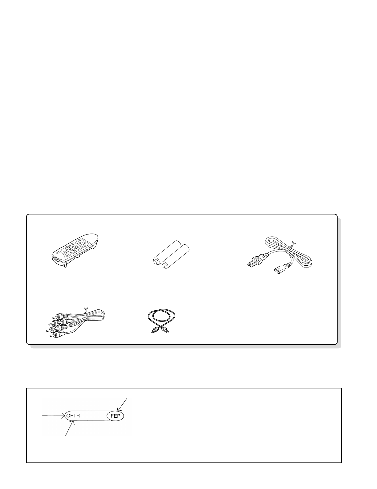
Remote control unit . . . . . . . . . 1
for remote control unit [size "AA"]
Batteries. . . . . . . . . . . . . . . . . . . . 2 AC cord . . . . . . . . . . . . . . . . . . . . . 1
Video/audio cable. . . . . . . . . . . . 1 Digital cord. . . . . . . . . . . . . . . . . . . 1
DV-403
CONTENTS / ACCESSORIES
Contents
CONTENTS / ACCESSORIES .................................. 2
DISASSEMBLY FOR REPAIR....................................3
BLOCK DIAGRAM....................................................12
CIRCUIT DESCRIPTION..........................................16
ADJUSTMENT..........................................................18
VOLTAGE CHART....................................................19
Note: There is different part in this manual as compared with a usual one because we use OEM
factory's data.
On "Circuit description", "Lubrication" and "Abbreviation of Logo", please refer to DV-303
service manual (B51-5561-00 or B51-5583-00)
WIRING DIAGRAM...................................................23
PC BOARD .............................................................. 24
SCHEMATIC DIAGRAM.......................................... 29
EXPLODED VIEW ....................................................54
PARTS LIST..............................................................57
SPECIFICATIONS ......................................Back cover
Accessories
How to read the schematic diagram
Connection of "from" or "to".
Port name
• There are some destinations in this schematic.
2
DISASSEMBLY FOR REPAIR
Extension
cable(C)
Extension cable(B)x2
Extension cable(A)
DV-403
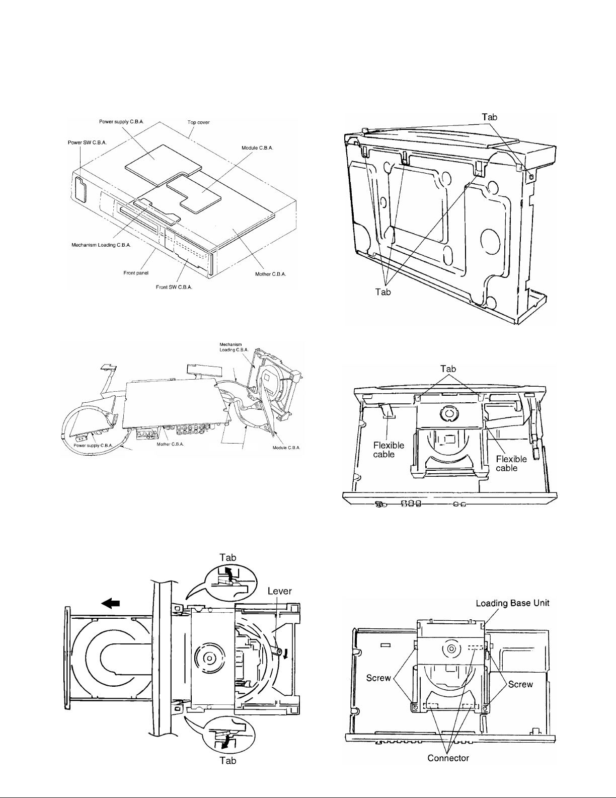
1. Assembling and Disassembling the Casing and Checking C.B.A.s
1-1 Casing Parts and C.B.A. Positions
1-2 Service Positions
Note
To inspect the loading base unit, position the left side
upward (as viewed from the front).
1-4 Disassembling the Front Panel
1. Release the 3 tabs on the bottom.
2. Release the 2 tabs on the left and right.
3. Release the 2 tabs.
4. Disconnect the 2 flexible cables.
1-3 Disassembling the Tray
1. Turn the lever clockwise.
2. Move the tray in the direction of the arrow until it locks.
3. Release the tab locks on the left and right, then pull out
the tray.
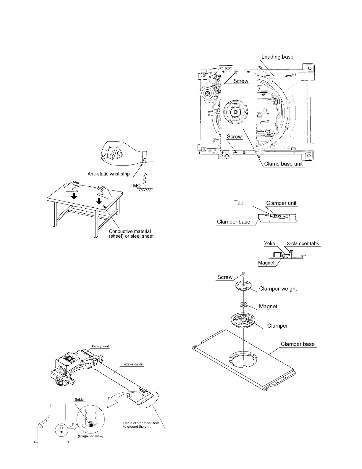
1-5 Disassembling the Loading Base Unit
1. Remove the 4 screws.
2. Pull out the loading base unit vertically.
Note
There is a danger of damaging the connectors.
3
DV-403
Extension
cable(C)
Extension cable(B)
Extension cable(B)
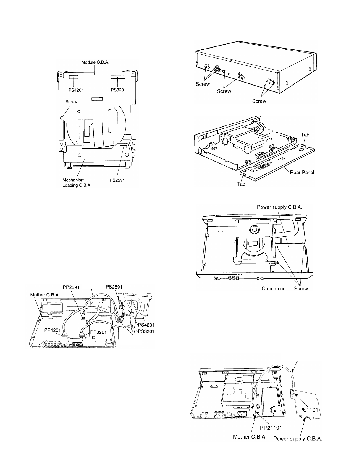
1-6 Checking the Module C.B.A.
1. Remove the screws.
DISASSEMBLY FOR REPAIR
2. Release the two tabs on the left and right.
2. Connect the module C.B.A. to the mother C.B.A. with the
extension cables for inspection.
• Extension cable (B)x2
Mother C.B.A. Module C.B.A.
PP4201-PS4201
PP3201-PS3201
3. Connect the mechanism loading C.B.A. to the mother
C.B.A. with the extension cable: for inspection.
Extension cable(C)
Mother C.B.A. Mechanism Loading C.B.A.
PP2591-PS2591
Note
Be sure to initialize the player whenever you replace a
C.B.A. (Refer to page17/4-1 Initializing the DVD Player.)
1-8 Checking the Power Supply C.B.A.
1. Remove the 3 screws.
2. Carefully pull out the power supply C.B.A.
Note
There is a danger of damaging the connectors.
3. Connect the power supply C.B.A. and the mother C.B.A.
with the extension cable for inspection.
• Extension cable(A) (connects the power supply C.B.A.
PS1101 and the mother C.B.A. PP1101)
Extension cable(A)
1-7 Disassembling the Rear Panel,
1. Remove all of the screws connected to the rear panel.
(The number of screws varies according to the model).
4
DISASSEMBLY FOR REPAIR
Extension cable(C)
Extension
cable(B)
Extension
cable(B)
DV-403
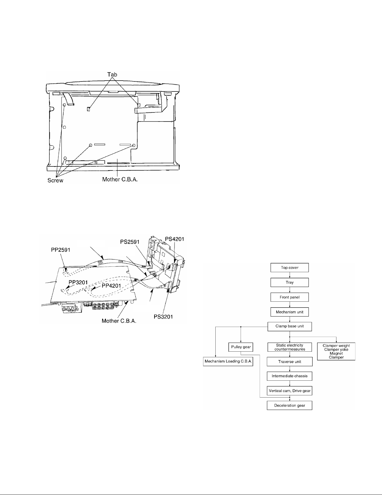
1-9 Checking the Mother C.B.A.
1. Remove the 4 screws.
2. Release the 2 tabs.
3. Checked by connecting the module C.B.A. and the mother C.B.A. with the extension cables.
Extension cable (B)x2
Module C.B.A. Mother C.B.A.
PS3201-PP3201
PS4201-PP4201
2. Assembling and Disassembling the Optical Pickup (Mechanical Parts)
The optical pickup can be damaged by static electricity from
your body. Be sure to take static electricity countermeasures
when working around the optical pickup.
2-1 Handling the Optical Pickup
The optical pickup can be damaged by static electricity
from your body. Be sure to take static electricity countermeasures when working around the optical pickup.
1. The optical pickup is an extremely high-precision mechanism. Do not subject it to strong impact.
2. To preserve the quality of the optical pickup replacement
parts during transport and installation, the terminals of
the laser diode are short-circuited. After replacing the
parts, use the proper procedure to return the laser diode
to its original condition. (Refer to page8/2-11 Assembling
the Optical Pickup.)
3. Testers cannot be used to check the laser diode of the
optical pickup. The power supply inside the tester can
easily damage the laser diode.
4. Take care when handling the flexible cable because
excessive force can cause it to break.
5. You cannot adjust the semifixed resistor for laser power
adjustment. Do not turn it.
2-2 Disassembly Procedure
Use the following procedure to replace major parts.
For the assembly procedure, follow the flow chart in reverse.
4. Checked by connecting the mechanism loading C.B.A.
and the mother C.B.A. with the extension cables.
Extension cable(C)
Mechanism Loading C.B.A. Mother C.B.A.
PS2591-PP4201
Note
Be sure to initialize the player whenever you replace a
C.B.A. (Refer to page17/4-1, Initializing the DVD player.)
5
DV-403
DISASSEMBLY FOR REPAIR
2-3 Static Electricity Countermeasures
The laser diode inside the traverse unit (optical pickup) can
be damaged by static electricity from your body. Be sure to
take static electricity countermeasures when working around
the optical pickup.
2-3-1 Static Electricity Countermeasure Methods
1. Ground yourself
Use an anti-static wrist strap to discharge static electrici-
ty from your body.
2. Ground the workbench
Lay a conductive material (sheet) or steel sheet on the
surface where the traverse unit (optical pickup) is to be
placed, then ground the sheet.
2-4 Disassembling the Clamp Base Unit
Remove the 2 screws.
2-5 Disassembling the Clamper Weight, Clamper
Yoke, Magnet and Clamper
1. Release the tab, and pull out the clamper.
2-3-2 Short-circuit the laser diode
Solder the land in the flexible cable of the optical pickup.
Notes
• Be sure to do this befer disconnecting the flexible cable
of the optical pickup from the module C.B.A.
• Use an anti-static soldering iron to short-circuit and
unshort-circuit laser diode.
(Recommended soldering iron: Hakko with ESD countermeasure)
• After you have finished repairing the laser diode, follow
the correct procedure to remove the solder from the
short-circuit location. (Refer to page5/2. Assembling and
Disassembling the Optical Pickup (Mechanical Parts).)
2. Release the 3 tabs on the clamper.
6
DISASSEMBLY FOR REPAIR
DV-403
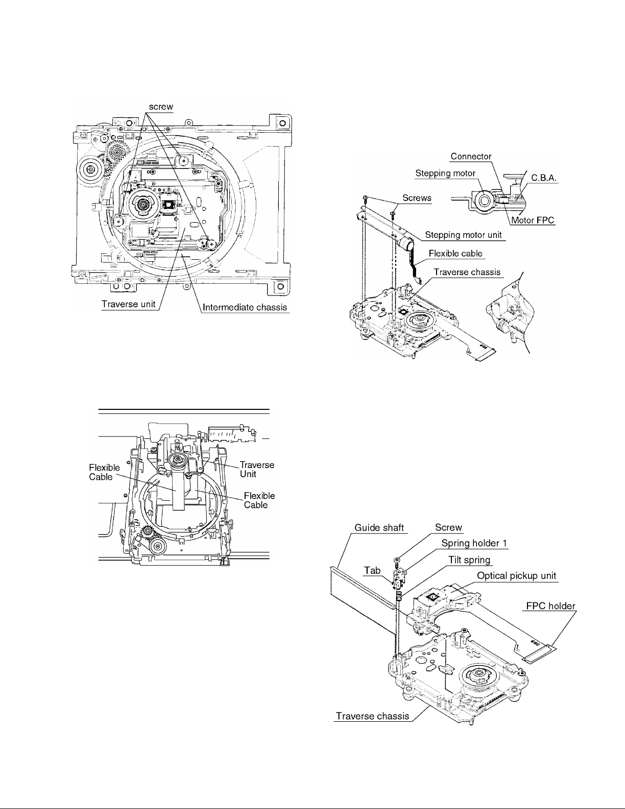
2-6 Disassembling the Traverse Unit
1. Remove the 3 screws.
Note
Be sure to take static electricitiy countermeasures befer
disconnecting the flexible cable.(Refer to page6/2-3 Static Electricity Countermeasures.)
2. Disconnect the 2 flexible cables.
2-7 Disassembling the Stepping Motor Unit
1. Disconnect the flexible cable.
2. Remove the 2 screws.
Note
Take care when handling the flexible cable because it
can be broken by excessive force.
2-8 Disassembling the Optical Pickup Unit
1. Remove the screw.
2. Release the tab, then remove spring holder 1.
Note
Be sure not to lose the spring.
3. Remove the guide shaft.
Note
Be sure to adjust the optical pickup tilt after replacing the
optical pickup.
(Refer to page9/2-13 Opitcal Pickup Tilt Adjustment.)
7
DV-403
DISASSEMBLY FOR REPAIR
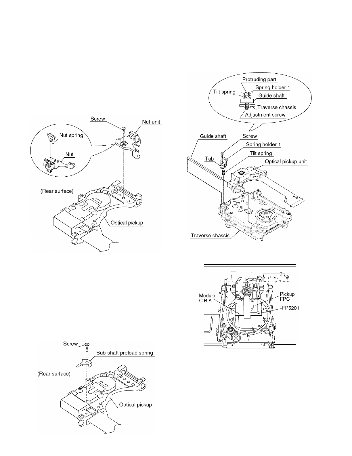
2-9 Disassembling the Nut Unit
1. Remove the screw.
Notes
• The nut unit is not part of the optical pickup.
Before replacing the optical pickup, remove the nut unit
for use with the new optical pickup.
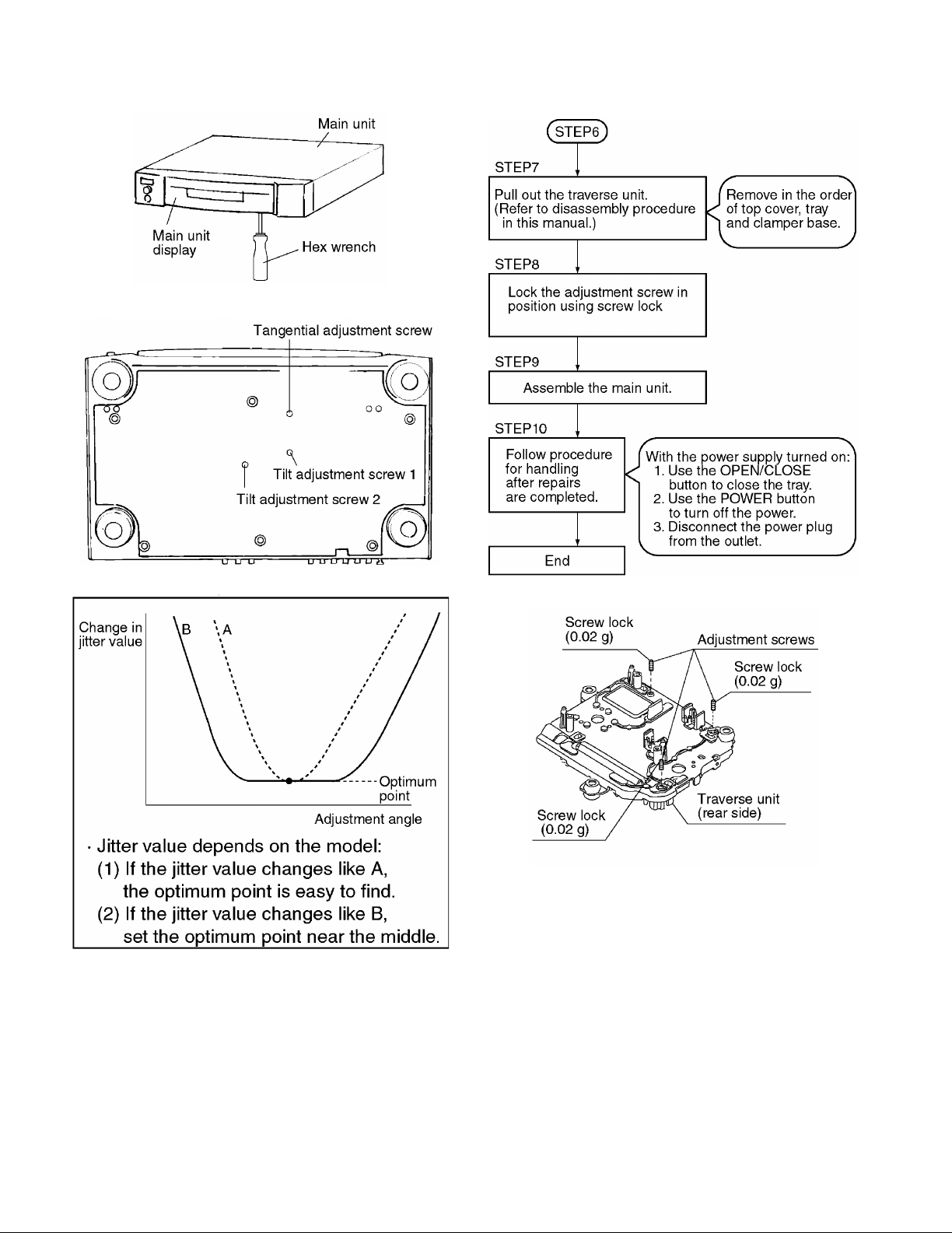
• After installation, use screw lock to lock the screw in position.
• When reassembling, use screw lock to lock the screw in
position after attaching it.
2-11 Assembling the Optical Pickup
1. Install the optical pickup.
Note
Take care not ot attach the tilt spring and guide shaft in
the wrong order.
2-10 Disassembling the Sub-Shaft Preload Spring
1. Remove the screw.
Notes
• Handle the sub-shaft preload spring carefully because the
shape of the tip is easily deformed.
• The sub-shaft preload spring is not part of the optical
pickup. Before replacing the optical pickup, remove the
sub-sahft preload spring for use with the new optical
pickup.
• After installation, use screw lock to lock the screw in position.
2. Insert the pickup FPC into connector FP5201 on the module C.B.A.
8
DISASSEMBLY FOR REPAIR
DV-403
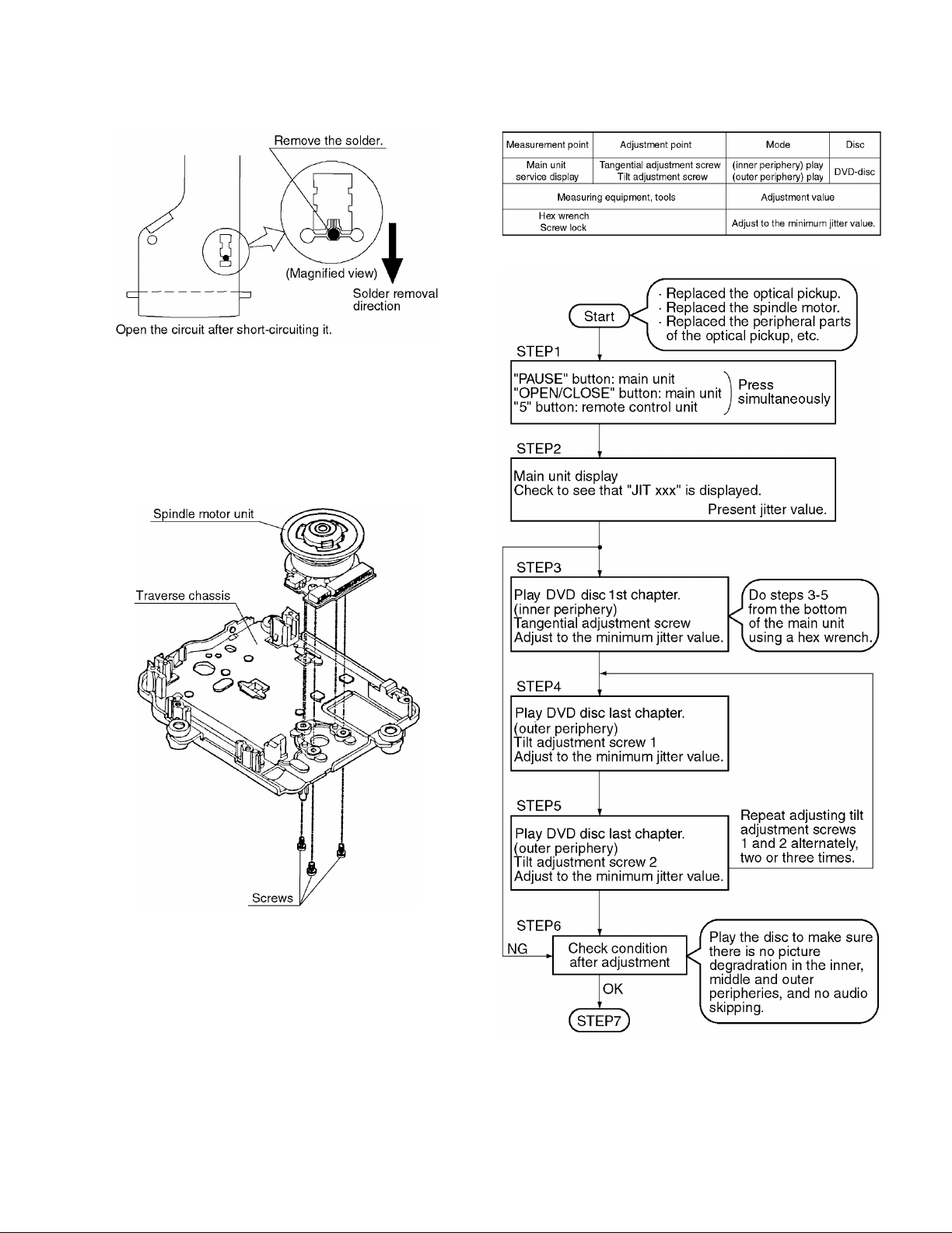
3. Remove the solder from the pickup FPC's soldered shortcircuit.
4. Adjust the optical pickup tilt after removing the solder.
(Refer to page 9/2-13 Optical Pickup Tilt Adjustment.)
2-12 Disassembling the Spindle Motor Unit
1. Remove the three screws.
Note
Be sure to adjust the optical pickup tilt after replacing the
spindle motor unit.
2-13 Optical Pickup Tilt Adjustment
9
DV-403
DISASSEMBLY FOR REPAIR
10
Notes
• Adjustment is generally unnecessary after replacing other
parts of the traverse unit. However, adjust if there is a
noticeable degradation in picture quality.
• Optical adjustments cannot be made inside the optical
pickup.
• Adjustment is generally unnecessary after replacing the
traverse unit.
DISASSEMBLY FOR REPAIR
DV-403
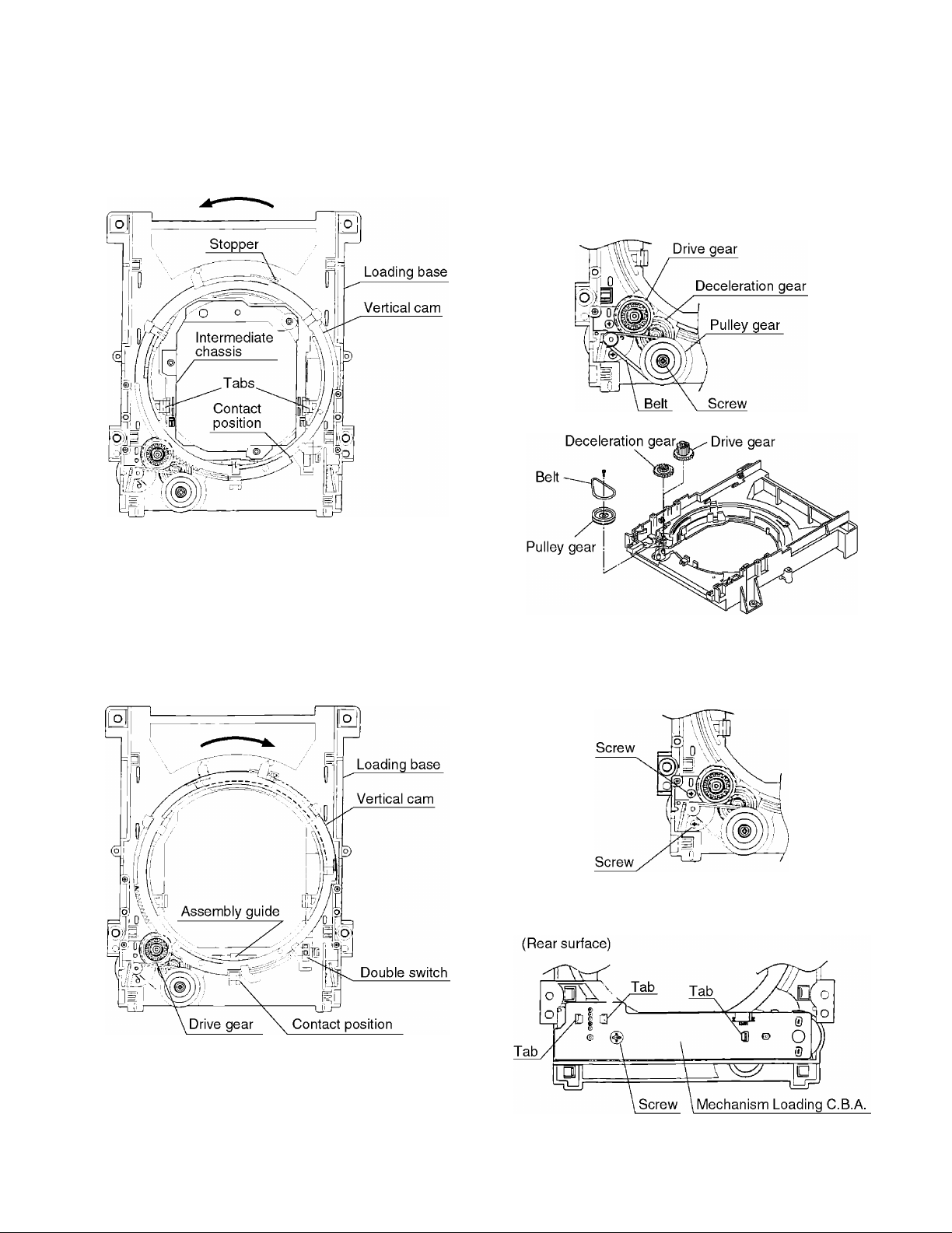
2-14 Disassembling the Intermediate Chassis
1. Push the stopper downward, then rotate it until it contacts
the Vertical cam.
2. Release the 2 tabs.
2-16 Disassembling the Pulley Gear and Decelera-
tion Gear
1. Remove the screw.
2. Remove the pulley gear.
3. Remove the belt.
4. Remove the deceleration gear.
2-15 Disassembling the Vertical cam and Drive
gear
1. Rotate the Vertical cam until it reaches the contact position.
2. Lift the Vertical cam straight upward to pull it out.
3. Remove the Drive gear.
2-17 Disassembling the Mechanism Loading
C.B.A.
1. Remove the 2 screws.
2. Remove the 2 screws.
3. Release the three tabs.
11
12
DV-403
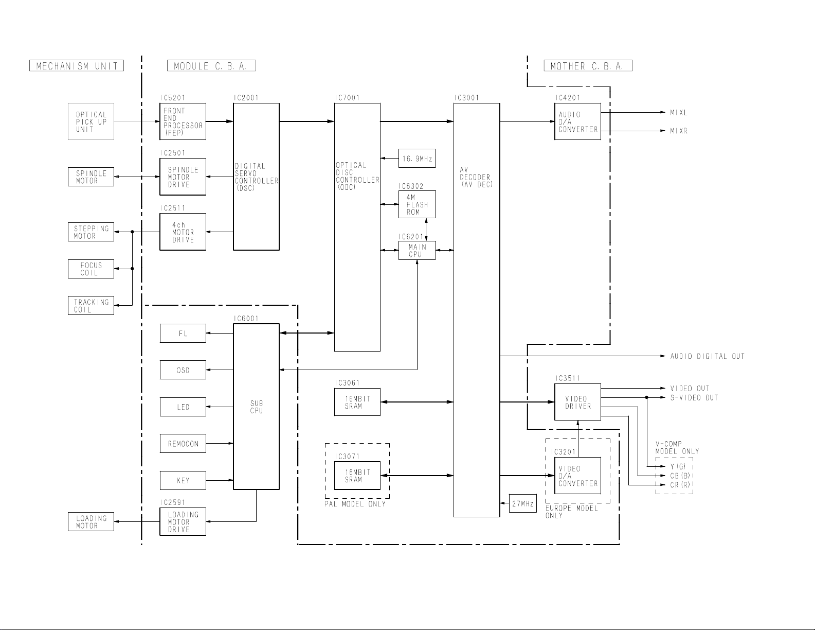
OVERAL BLOCK DIAGRAM
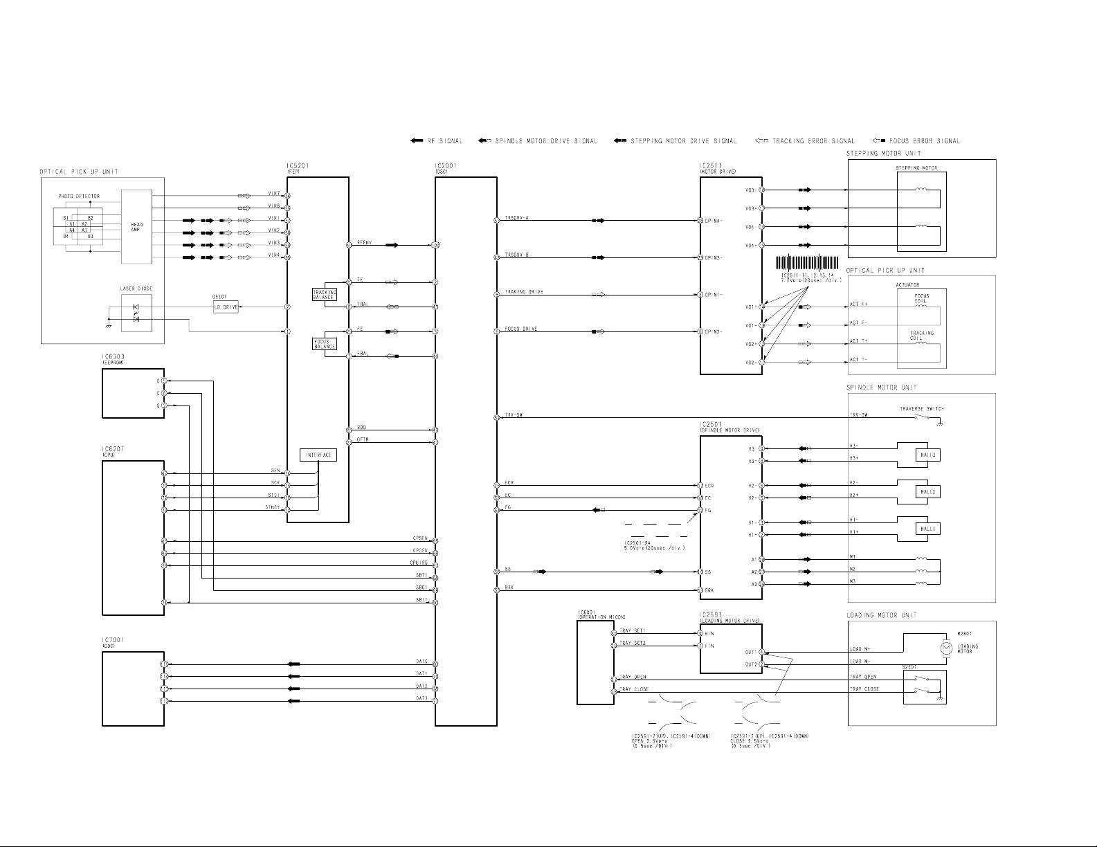
SERVO BLOCK DIAGRAM
DV-403
13
14
DV-403
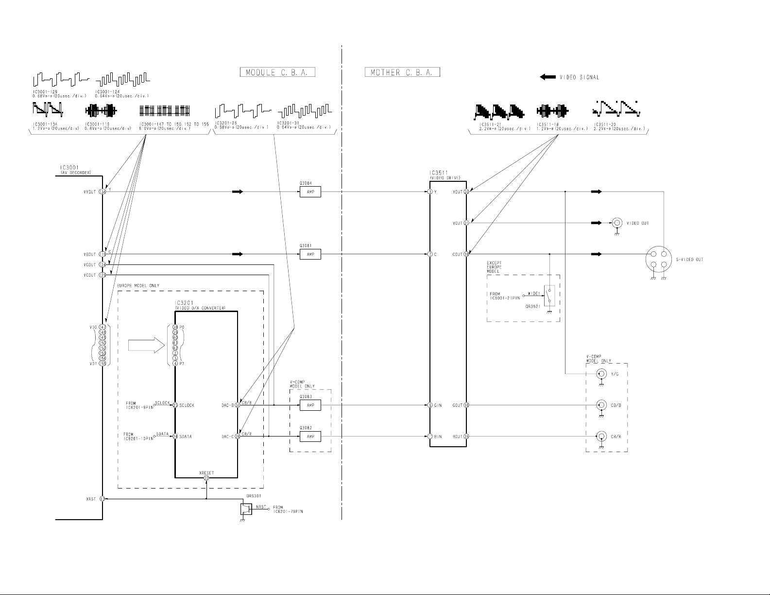
VIDEO BLOCK DIAGRAM
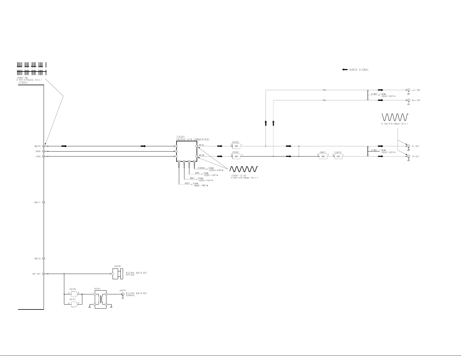
AUDIO BLOCK DIAGRAM
DV-403
15
 Loading...