

DVD VCD CD PLAYER
70%
STANDBY
VIRTUAL
SURROUND
OPEN/CLOSE
DIGITAL OUTPUT
(PCM/BIT STREAM)
OPTICAL COAXIAL
AUDIO OUTPUT VIDEO OUTPUT
VIDEO OUTPUT
SELECTION
COMPONENT
VIDEO OUTPUT
Cr
Cb Y
S-VIDEO
AC IN~
L
R
DV-303/DVF-5020/K5020
SERVICE MANUAL
REVISED
© 1999-10/B51-5583-00 (K/K) 1836
Please use this manual instead of DV-303's manual (B51-5561-00), when repair of DV-303.
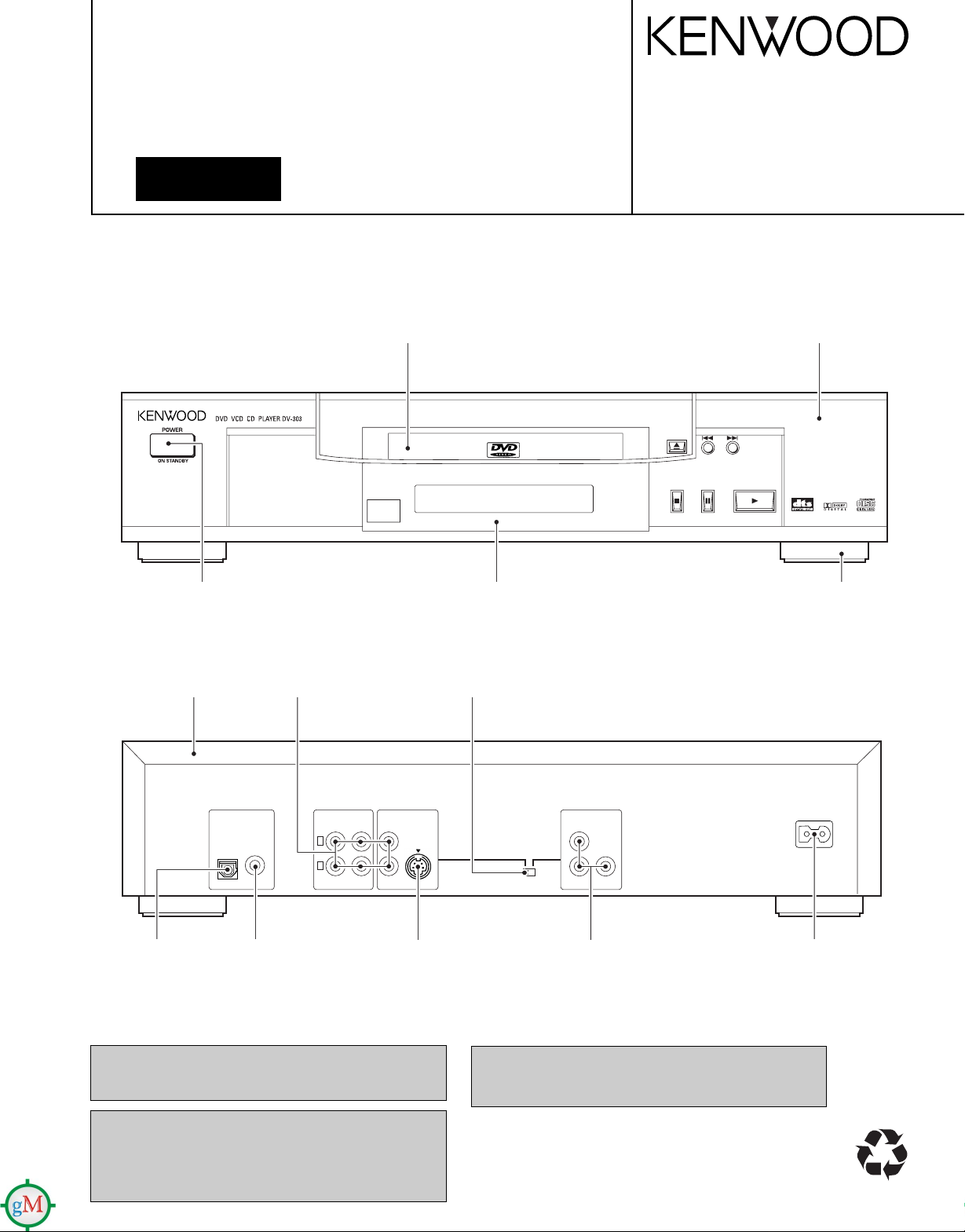
Front panel
(A60-1788-08)
Leg
(J02-1468-08)
Power button
(K27-2389-08)
Tray top
(A29-1088-08)
Front cover
(B10-3573-08)
Top cover
(A01-3749-08)
Oscillating module
(W02-2736-08)
In compliance with Federal Regulations, following are reproductions of labels on, or inside the product relating to laser
product safety.
KENWOOD-Crop. certifies this equipment conforms to DHHS
Regulations No. 21 DFR 1040. 10, Chapter 1, Subchapter J.
DANGER : Laser radiation when open and interlock
defeated.
AVOID DIRECT EXPOSURE TO BEAM
RCA jack
(E63-1134-08)
Pin jack
(E63-1135-08)
Switch
(S90-0134-08)
Y/C connector
(E40-8534-08)
Pin jack
(E63-1133-08)
Connector
(E40-8535-08)
Figure is DV-303.
Caution : No connection of ground line if disassemble
NOTE : Please use the remote controller
the unit. Please connect the ground line on
rear panel, PCBs, Chassis and some others.
for self-diagnosis and tilt adjustment.
DV-303/DVF-5020/K5020
(A70-1353-08): K,K1,Y
(A70-1369-08): M
(E30-2937-08): K,K1
(E30-2946-08): Y,M
(E30-2938-08) (E30-2365-05)
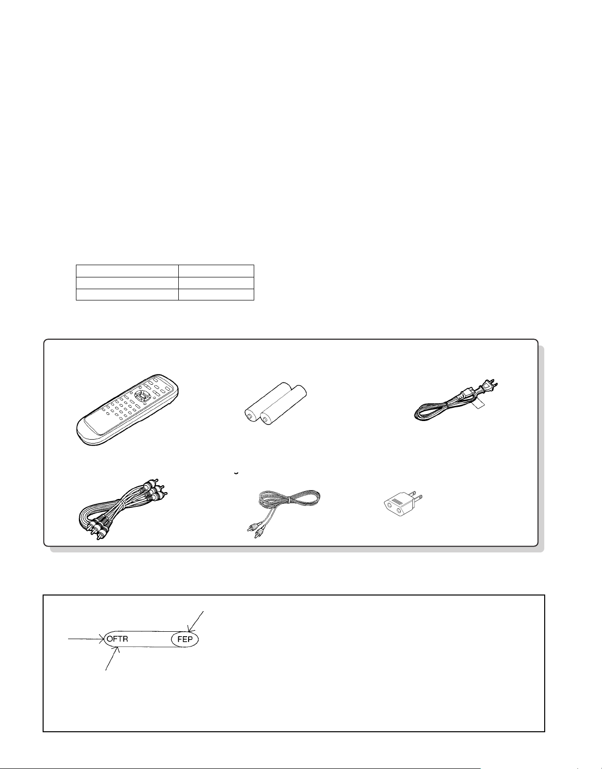
Remote control unit . . . . . . . . . 1
for remote control unit [size "AA"]
Batteries. . . . . . . . . . . . . . . . . . . . 2 AC cord. . . . . . . . . . . . . . . . . . . .. . 1
Video/audio cable. . . . . . . . . . . . 1 Digital cord. . . . . . . . . . . . . . . . . . . 1
(E03-0115-05): M
Ac plug adapter. . . . . . . . . . . . . . . 1
Use to adapt the plug
on the power cord to
the shape of the wall outlet.
(Accessory only for regions where use is
necesary.)
CONTENTS / ACCESSORIES
Contents
CONTENTS / ACCESSORIES .................................. 2
DISASSEMBLY FOR REPAIR....................................3
BLOCK DIAGRAM....................................................13
CIRCUIT DESCRIPTION..........................................17
ADJUSTMENT..........................................................21
ABBREVIATION........................................................22
VOLTAGE CHART....................................................24
"Disassembly for repair" is for DV-303.
Note: There is different part in this manual as compared with a usual one because we use OEM
factory's data.
KENWOOD MODEL OEM MODEL
DV-303,DVF-5020 DVD-A120U
DVF-K5020 DVD-A160EN
WIRING DIAGRAM...................................................30
PC BOARD .............................................................. 32
SCHEMATIC DIAGRAM.......................................... 41
EXPLODED VIEW ....................................................93
PARTS LIST..............................................................96
SPECIFICATIONS ......................................Back cover
Accessories
How to read the schematic diagram
Connection of "from" or "to".
• There are some destinations in this schematic.
Port name
• Figures which is more than 20,000 is omitted first digit in Mic jack and Mic volume circuit.
(Example) R4001
2
î R24001
DV-303/DVF-5020/K5020
DISASSEMBLY FOR REPAIR
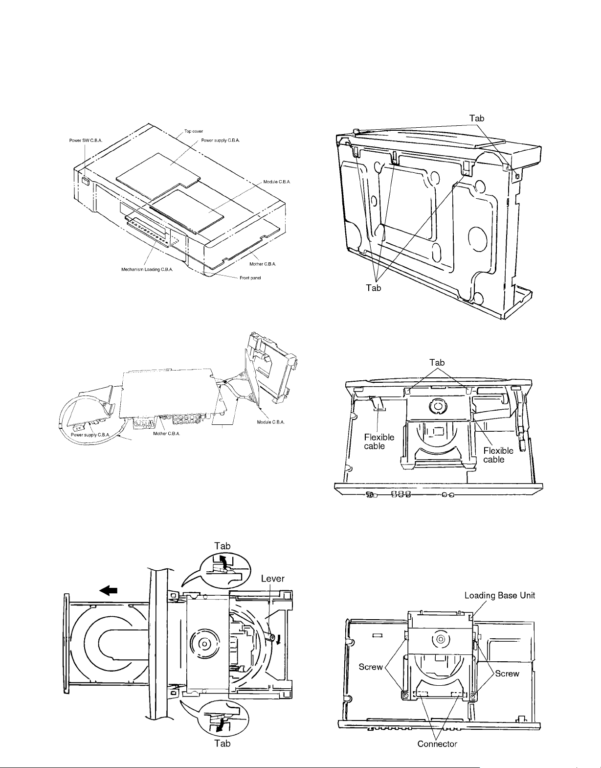
1. Assembling and Disassembling the Casing and Checking C.B.A.s (DV-303)
1-1 Casing Parts and C.B.A. Positions
1-2 Service Positions
Note
To inspect the loading base unit, position the left side
upward (as viewed from the front).
1-4 Disassembling the Front Panel
1. Release the 3 tabs on the bottom.
2. Release the 2 tabs on the left and right.
3. Release the 2 tabs.
4. Disconnect the 2 flexible cables.
Extension cable (B)x2
Extension cable (A)
1-3 Disassembling the Tray
1. Turn the lever clockwise.
2. Move the tray in the direction of the arrow until it locks.
3. Release the tab locks on the left and right, then pull out
the tray.
1-5 Disassembling the Loading Base Unit
1. Remove the 4 screws.
2. Pull out the loading base unit vertically.
Note
There is a danger of damaging the connectors.
3
DV-303/DVF-5020/K5020
DISASSEMBLY FOR REPAIR
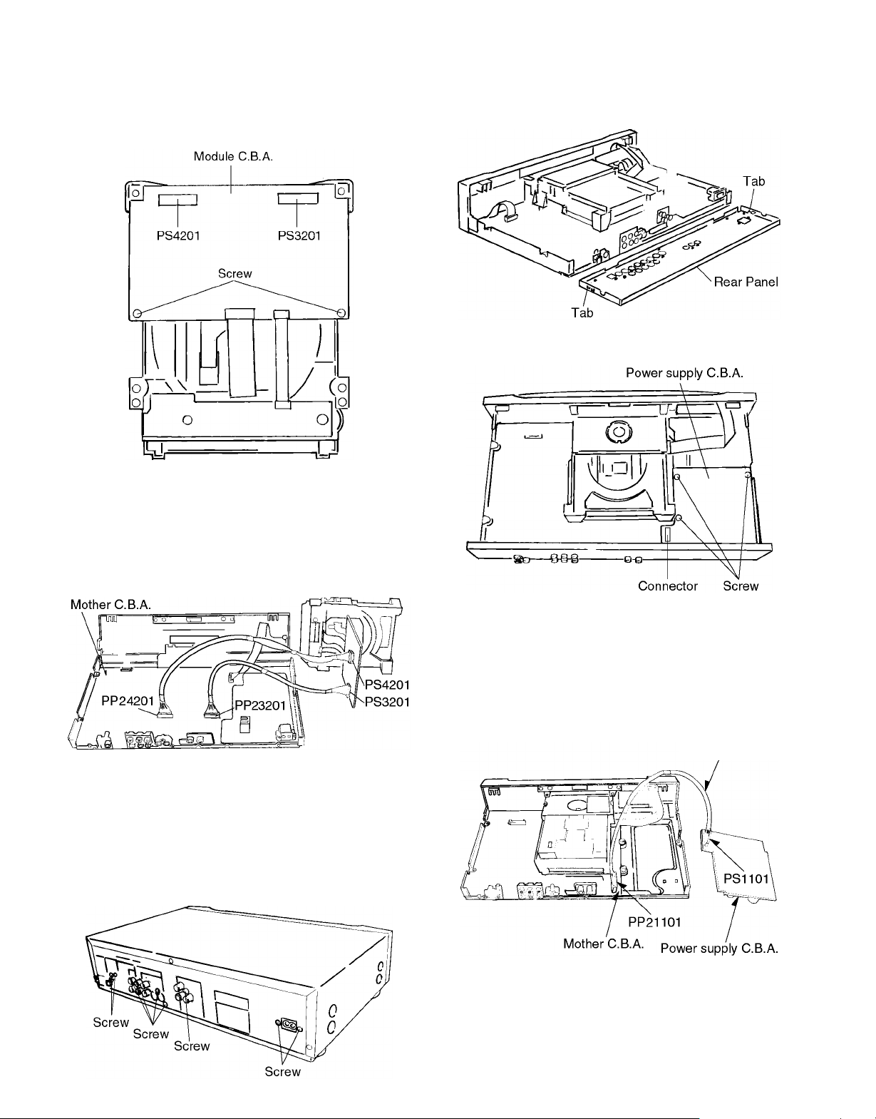
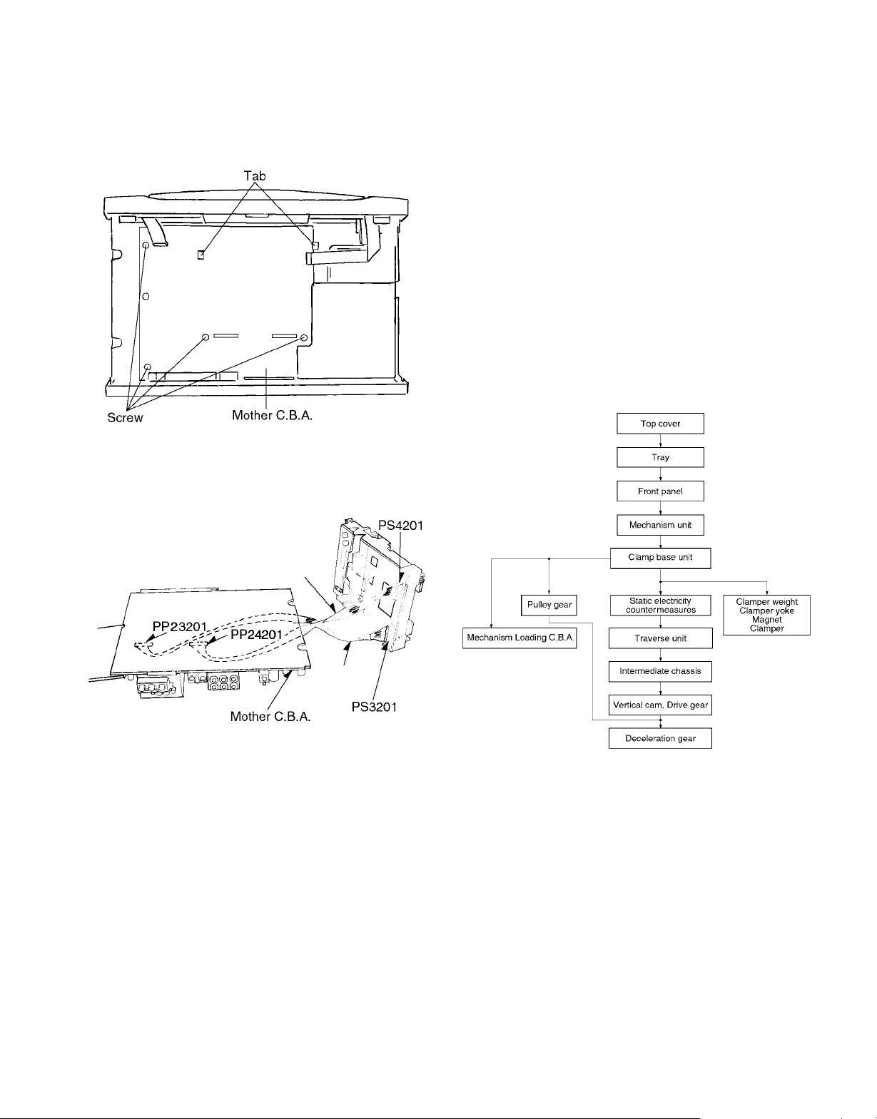
1-6 Checking the Module C.B.A.
1. Remove the 2 screws.
2. Connect the module C.B.A. to the mother C.B.A. with the
extension cables for inspection.
• Extension cable (B)x2
Mother C.B.A. Module C.B.A.
PP24201-PS4201
PP23201-PS3201
2. Release the two tabs on the left and right.
1-8 Checking the Power Supply C.B.A.
1. Remove the 3 screws.
Note
Be sure to initialize the player whenever you replace a
C.B.A. (Refer to page21/4-1 Initializing the DVD Player.)
1-7 Disassembling the Rear Panel,
1. Remove all of the screws connected to the rear panel.
(The number of screws varies according to the model).
2. Carefully pull out the power supply C.B.A.
Note
There is a danger of damaging the connectors.
3. Connect the power supply C.B.A. and the mother C.B.A.
with the extension cable for inspection.
• Extension cable(A) (connects the power supply C.B.A.
PS1101 and the mother C.B.A. PP21101)
Extension cable(A)
4
DV-303/DVF-5020/K5020
DISASSEMBLY FOR REPAIR
1-9 Checking the Mother C.B.A.
1. Remove the 5 screws.
2. Release the 2 tabs.
3. Checked by connecting the module C.B.A. and the mother C.B.A. with the extension cables.
Extension cable (B)x2
Module C.B.A. Mother C.B.A.
PS3201-PP23201
PS4201-PP24201
2. To preserve the quality of the optical pickup replacement
parts during transport and installation, the terminals of
the laser diode are short-circuited. After replacing the
parts, use the proper procedure to return the laser diode
to its original condition. (Refer to page9/2-12 Assembling
the Optical Pickup.)
3. Testers cannot be used to check the laser diode of the
optical pickup. The power supply inside the tester can
easily damage the laser diode.
4. Take care when handling the flexible cable because
excessive force can cause it to break.
5. You cannot adjust the semifixed resistor for laser power
adjustment. Do not turn it.
2-2 Disassembly Procedure
Use the following procedure to replace major parts.
For the assembly procedure, follow the flow chart in reverse.
Extension cable(B)
Extension
cable(B)
Note
Be sure to initialize the player whenever you replace a
C.B.A. (Refer to page21/4-1, Initializing the DVD player.)
2. Assembling and Disassembling the Optical Pickup (Mechanical Parts)
The optical pickup can be damaged by static electricity from
your body. Be sure to take static electricity countermeasures
when working around the optical pickup.
2-1 Handling the Optical Pickup
The optical pickup can be damaged by static electricity
from your body. Be sure to take static electricity countermeasures when working around the optical pickup.
1. The optical pickup is an extremely high-precision mechanism. Do not subject it to strong impact.
5
DV-303/DVF-5020/K5020
DISASSEMBLY FOR REPAIR
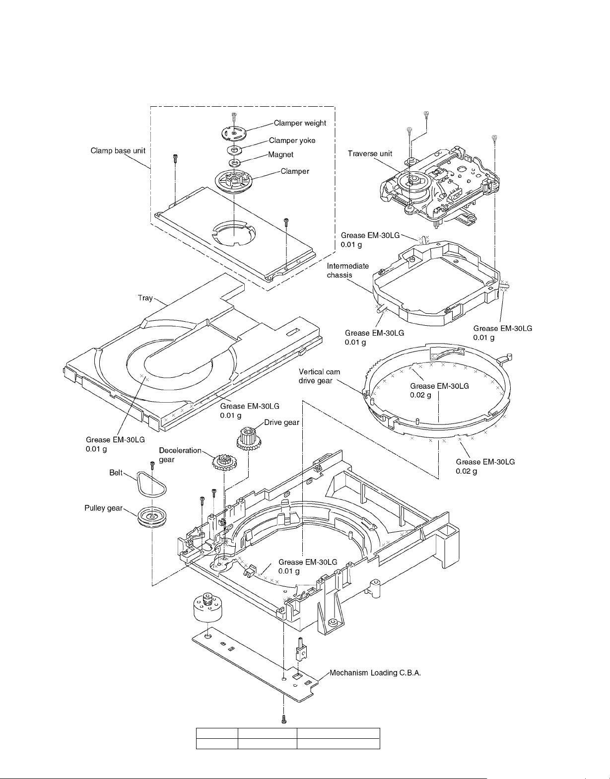
2-3Lubricating the Loading Base Unit
When replacing parts, lubricate the parts maked “xxx” in the diagram
Grease 410-0013-05 Grease EM-30LG
6
Part number Service Tool
DV-303/DVF-5020/K5020
DISASSEMBLY FOR REPAIR
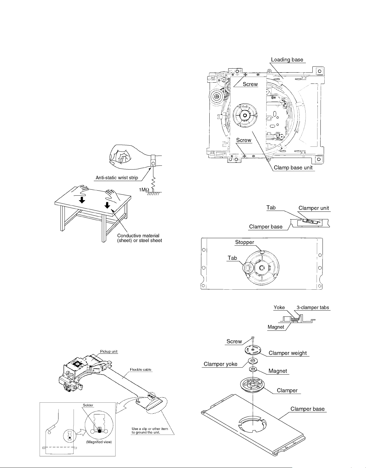
2-4 Static Electricity Countermeasures
The laser diode inside the traverse unit (optical pickup) can
be damaged by static electricity from your body. Be sure to
take static electricity countermeasures when working around
the optical pickup.
2-4-1 Static Electricity Countermeasure Methods
1. Ground yourself
Use an anti-static wrist strap to discharge static electrici-
ty from your body.
2. Ground the workbench
Lay a conductive material (sheet) or steel sheet on the
surface where the traverse unit (optical pickup) is to be
placed, then ground the sheet.
2-5 Disassembling the Clamp Base Unit
Remove the 2 screws.
2-6 Disassembling the Clamper Weight, Clamper
Yoke, Magnet and Clamper
1. Release the tab, and pull out the clamper.
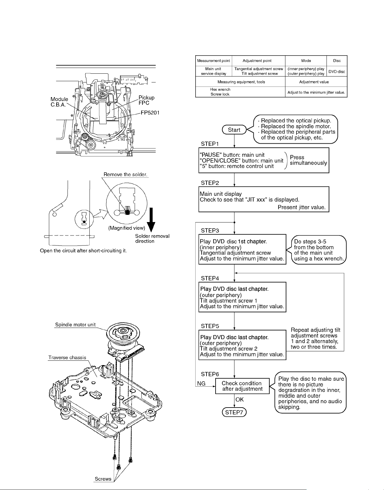
2-4-2 Short-circuit the laser diode
Solder the land in the flexible cable of the optical pickup.
Notes
• Be sure to do this befer disconnecting the flexible cable
of the optical pickup from the module C.B.A.
• Use an anti-static soldering iron to short-circuit and
unshort-circuit laser diode.
(Recommended soldering iron: Hakko with ESD countermeasure)
• After you have finished repairing the laser diode, follow
the correct procedure to remove the solder from the
short-circuit location. (Refer to page5/2. Assembling and
Disassembling the Optical Pickup (Mechanical Parts).)
2. Release the 3 tabs on the clamper.
7
DV-303/DVF-5020/K5020
DISASSEMBLY FOR REPAIR
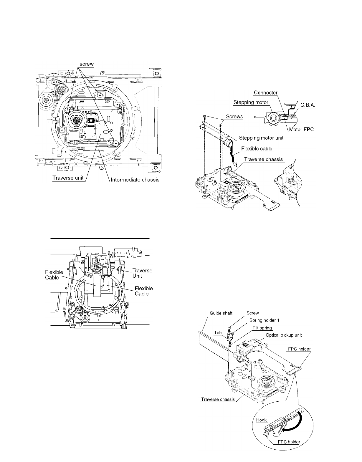
2-7 Disassembling the Traverse Unit
1. Remove the 3 screws.
Note
Be sure to take static electricitiy countermeasures befer
disconnecting the flexible cable.(Refer to page7/2-4 Static Electricity Countermeasures.)
2. Disconnect the 2 flexible cables.
2-8 Disassembling the Stepping Motor Unit
1. Disconnect the flexible cable.
2. Remove the 2 screws.
Note
Take care when handling the flexible cable because it
can be broken by excessive force.
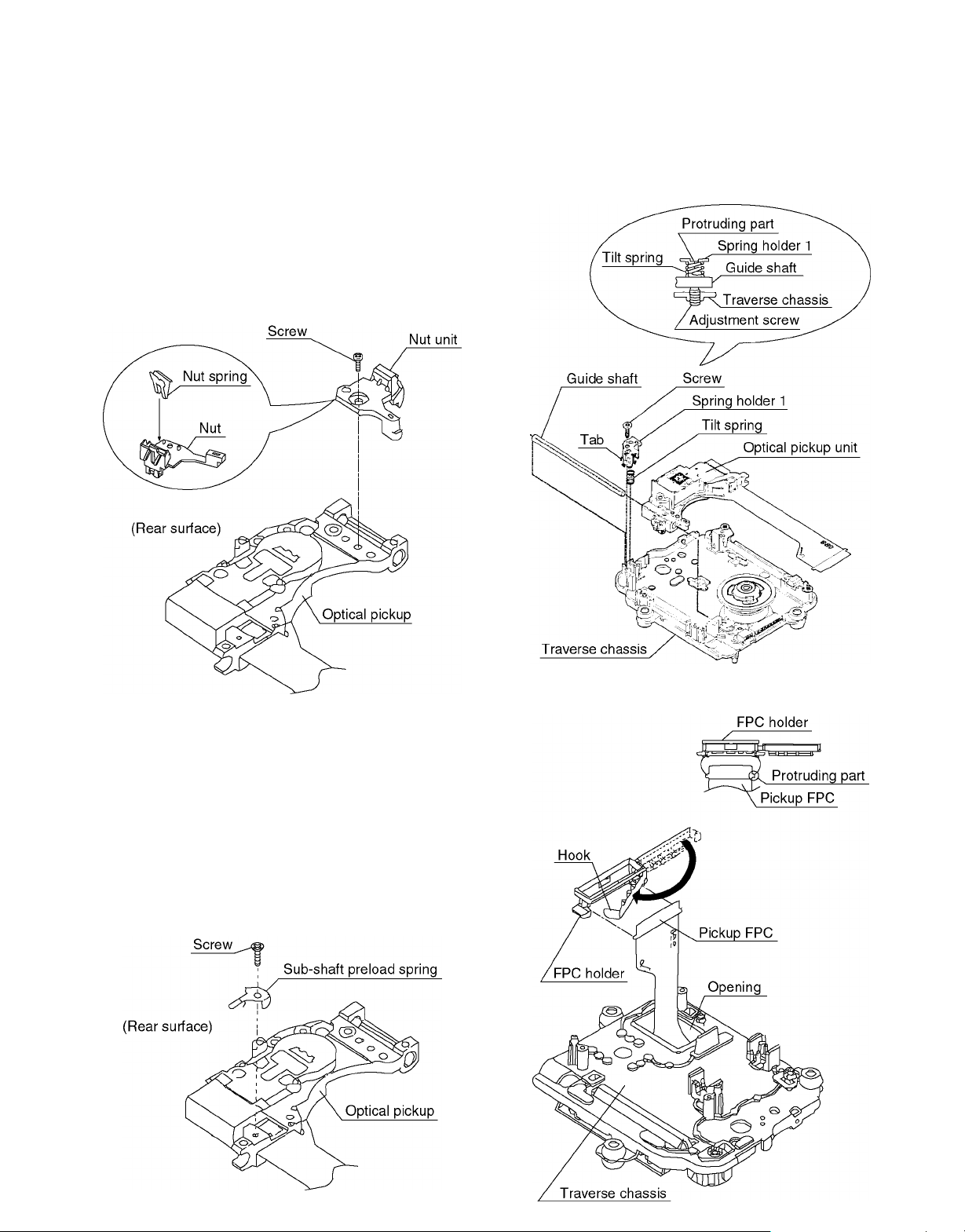
2-9 Disassembling the Optical Pickup Unit
1. Remove the hook of the FPC holder, then remove the
FPC holder itself.
2. Remove the screw.
3. Release the tab, then remove spring holder 1.
Note
Be sure not to lose the spring.
4. Remove the guide shaft.
Note
Be sure to adjust the optical pickup tilt after replacing the
optical pickup.
(Refer to page10/2-14 Opitcal Pickup Tilt Adjustment.)
8
DV-303/DVF-5020/K5020
DISASSEMBLY FOR REPAIR
2-10 Disassembling the Nut Unit
1. Remove the screw.
Notes
• The nut unit is not part of the optical pickup.
Before replacing the optical pickup, remove the nut unit
for use with the new optical pickup.
• After installation, use screw lock to lock the screw in position.
• When reassembling, use screw lock to lock the screw in
position after attaching it.
2-12 Assembling the Optical Pickup
1. Install the optical pickup.
Note
Take care not ot attach the tilt spring and guide shaft in
the wrong order.
2-11 Disassembling the Sub-Shaft Preload Spring
1. Remove the screw.
Notes
• Handle the sub-shaft preload spring carefully because the
shape of the tip is easily deformed.
• The sub-shaft preload spring is not part of the optical
pickup. Before replacing the optical pickup, remove the
sub-sahft preload spring for use with the new optical
pickup.
• After installation, use screw lock to lock the screw in position.
2. Fit the protruding part of the pickup FPC into the convexpart of the FPC holder to install it.
9
DV-303/DVF-5020/K5020
DISASSEMBLY FOR REPAIR
3. Insert the pickup FPC into connector FP5201 on the module C.B.A.
4. Remove the solder from the pickup FPC's soldered shortcircuit.
2-14 Optical Pickup Tilt Adjustment
5. Adjust the optical pickup tilt after removing the solder.
(Refer to page10/2-14 Optical Pickup Tilt Adjustment.)
2-13 Disassembling the Spindle Motor Unit
1. Remove the three screws.
Note
Be sure to adjust the optical pickup tilt after replacing the
spindle motor unit.
10
DV-303/DVF-5020/K5020
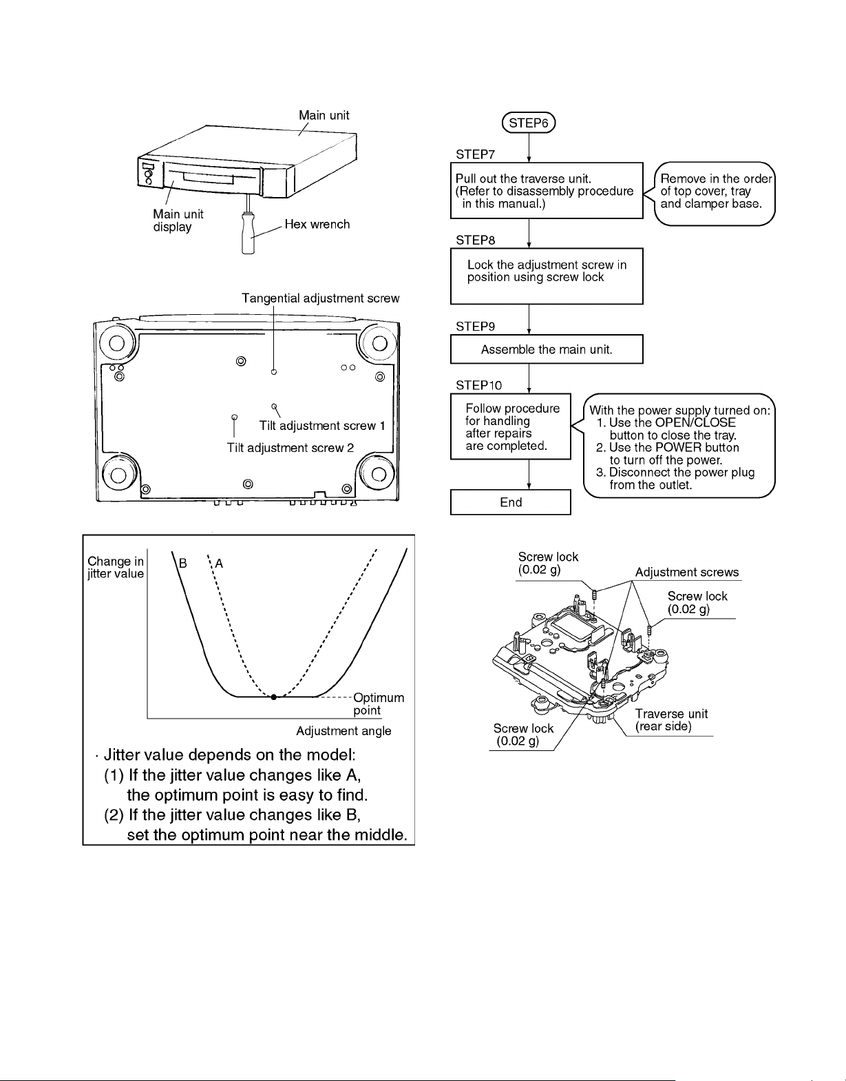
DISASSEMBLY FOR REPAIR
Notes
• Adjustment is generally unnecessary after replacing other
parts of the traverse unit. However, adjust if there is a
noticeable degradation in picture quality.
• Optical adjustments cannot be made inside the optical
pickup.
• Adjustment is generally unnecessary after replacing the
traverse unit.
• Adjustment is generally unnecessary after replacing the
traverse unit.
11
DV-303/DVF-5020/K5020
DISASSEMBLY FOR REPAIR
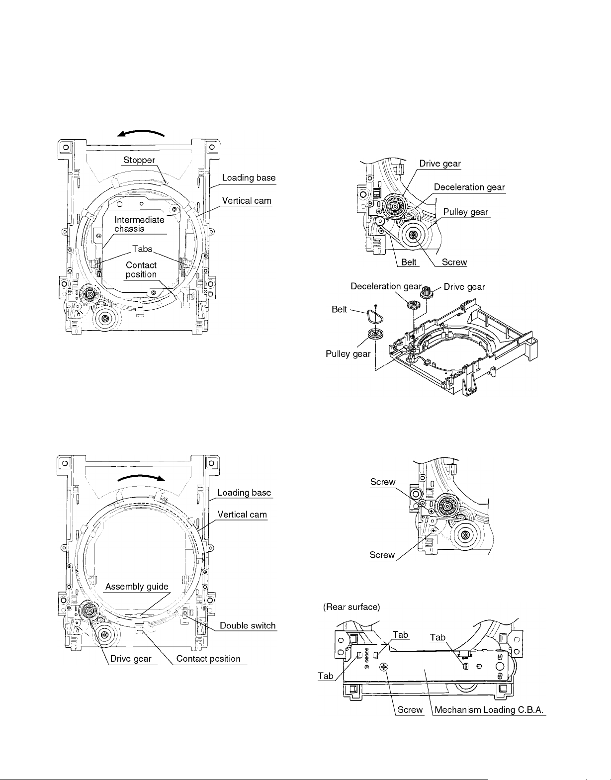
2-15 Disassembling the Intermediate Chassis
1. Push the stopper downward, then rotate it until it contacts
the Vertical cam.
2. Release the 2 tabs.
2-17 Disassembling the Pulley Gear and Decelera-
tion Gear
1. Remove the screw.
2. Remove the pulley gear.
3. Remove the belt.
4. Remove the deceleration gear.
2-16 Disassembling the Vertical cam and Drive
gear
1. Rotate the Vertical cam until it reaches the contact position.
2. Lift the Vertical cam straight upward to pull it out.
3. Remove the Drive gear.
2-18 Disassembling the Mechanism Loading
C.B.A.
1. Remove the 2 screws.
2. Remove the 2 screws.
3. Release the three tabs.
12
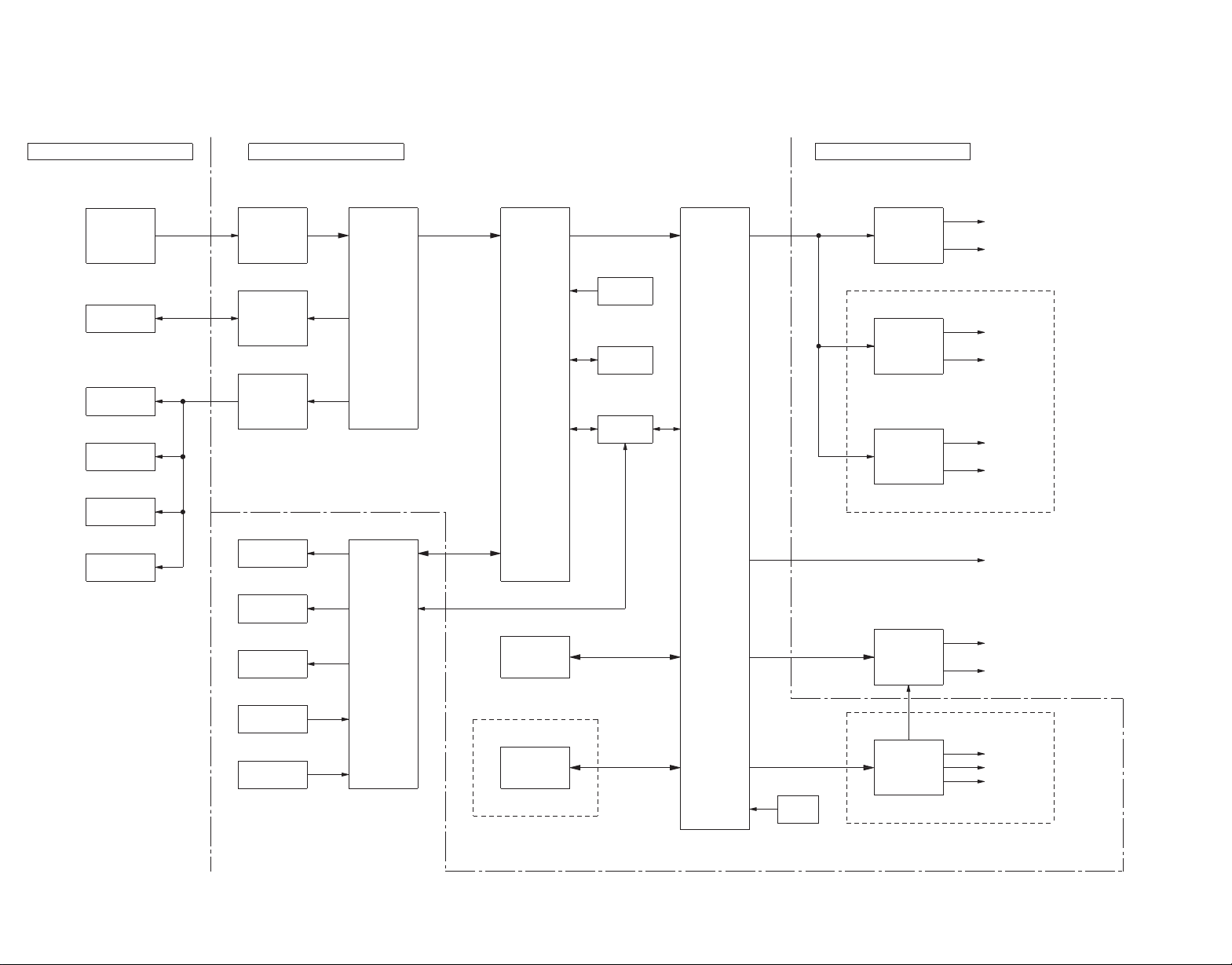
27MHz
RGB VIDEO/COMPONENT VIDEO OUT MODEL ONLY
ONLY
MODEL
5.1ch
AUDIO
AUDIO DIGITAL OUT
IC3201
MOTHER C.B.A.
PAL MODEL ONLY
IC3061
IC3051
IC6001
IC2511
IC2501
MECHANISM UNIT
MODULE C.B.A.
CR(R)
CB(B)
Y(G)
S-VIDEO OUT
VIDEO OUT
IC3531
IC4221
IC4211
IC4201
CNT
SW
SL
SR
FR
FL
CONVERTER
D/A
VIDEO
DRIVER
VIDEO
CONVERTER
D/A
AUDIO
CONVERTER
D/A
AUDIO
CONVERTER
D/A
AUDIO
IC3001IC7001IC2001IC5202
(AV DEC)
DECODER
AV
SRAM
4BIT
(ODC)
CONTROLLER
DISC
OPTICAL
SRAM
16BIT
COIL
TRACKING
COIL
FOCUS
MOTOR
STEPPING
CPU
SUB
KEY
REMOCON
LED
OSD
FL
(DSC)
CONTROLLER
SERVO
DIGITAL
IC6302
IC6201
CPU
MAIN
DRAM
4M
16.9MHz
DRIVE
MOTOR
4ch
MOTOR
LOADING
DRIVE
MOTOR
SPINDLE
MOTOR
SPINDLE
(FEP)
PROCESSOR
END
FRONT
UNIT
PICK UP
OPTICAL
OVERALL BLOCK DIAGRAM
DV-303/DVF-5020/K5020
13
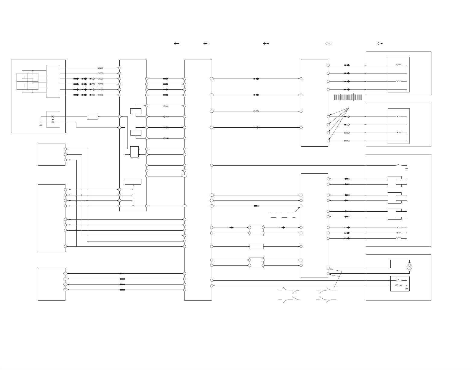
14
(0.5sec./DIV.)
CLOSE 2.5Vp-p
IC2501-25(UP),IC2501-27(DOWN)
5.0Vp-p(20usec./div.)
IC2501-24
7.2Vp-p(20usec./div.)
IC2511-11,12,13,14
(0.5sec./DIV.)
OPEN 2.5Vp-p
IC2501-25(UP),IC2501-27(DOWN)
RF SIGNAL
SPINDLE MOTOR DRIVE SIGNAL STEPPING MOTOR DRIVE SIGNAL
TRACKING ERROR SIGNAL
FOCUS ERROR SIGNAL
BRK
FIN
RIN
SS
FGC
FG
EC
ECR
OPIN2-
OPIN1-
OPIN3-
OPIN4-
TRAY CLOSE
TRAY OPEN
BRK
TRAY SET2
TRAY SET1
SS
FGC
FG
EC
ECR
TRV-SW
FOCUS DRIVE
TRAKING DRIVE
TRSDRV-B
TRSDRV-A
X TRON
OFTR
BDO
JIT OUT
LDONA
LDONB
FBAL
FE
TBAL
TE
RDCKP
RDCKN
RDTP
RDTN
VIN4
VIN3
VIN2
VIN1
VIN5
VIN6
STNBY
STD1
SCK
SEN
DAT3
DAT2
DAT1
DAT0
SBI1
SBO1
SBT1
CPUIRQ
CPCEN
CPSEN
OUT2
OUT1
A3
A2
A1
H1+
H1-
H2+
H2-
H3+
H3-
VO2-
VO2+
VO1-
VO1+
VO4+
VO4-
VO3+
VO3-
Q
C
D
OPTICAL PICK UP UNIT
PHOTO DETECTOR
B3B4
B2B1
A3A2A4
A1
LASER DIODE
AMP
HEAD
Q5201
LD DRIVE
4
3
IC6303
(EEPROM)
AMP
115
114
113
112
71
76
50
60
52
72
70
55
2
6
5
IC6201
(CPU)
IC7001
(ODC)
INTERFACE
BALANCE
FOCUS
BALANCE
TRACKING
22
21
20
19
97
96
95
94
92
91
2
3
2
1
9
23
66
65
64
12
13
28
50
49
48
47
(FEP)
IC5202
61
63
62
60
38
37
36
35
34
33
128
107
44
81
98
93
20
91
43
42
41
40
1
7
8
13
12
16
14
111
120
121
11
103
102
105
104
23
26
9
2
3
4
5
6
7
16
11
10
15
12
19
18
25
27
23
26
28
11
12
13
14
15
16
17
18
6
3
(DSC)
IC2001
QR2502
5
4
1
3
AMP
QR2503
QR2501
AMP
5
4
1
3
AMP
(MOTOR DRIVE)
(SPINDLE MOTOR DRIVE)
IC2501
IC2511
M2601
LOAD M-
LOAD M+
MOTOR
LOADING
S2601
TRAY OPEN
TRAY CLOSE
M3
M2
M1
H1-
HALL1
H1+
H2-
H2+
HALL2
H3+
H3-
TRV-SW
HALL3
TRAVERSE SWITCH
ACT T-
ACT T+
ACT F-
ACT F+
STEPPING MOTOR UNIT
STEPPING MOTOR
LOADING MOTOR UNIT
SPINDLE MOTOR UNIT
OPTICAL PICK UP UNIT
ACTUATOR
COIL
TRACKING
COIL
FOCUS
DV-303/DVF-5020/K5020
SERVO BLOCK DIAGRAM
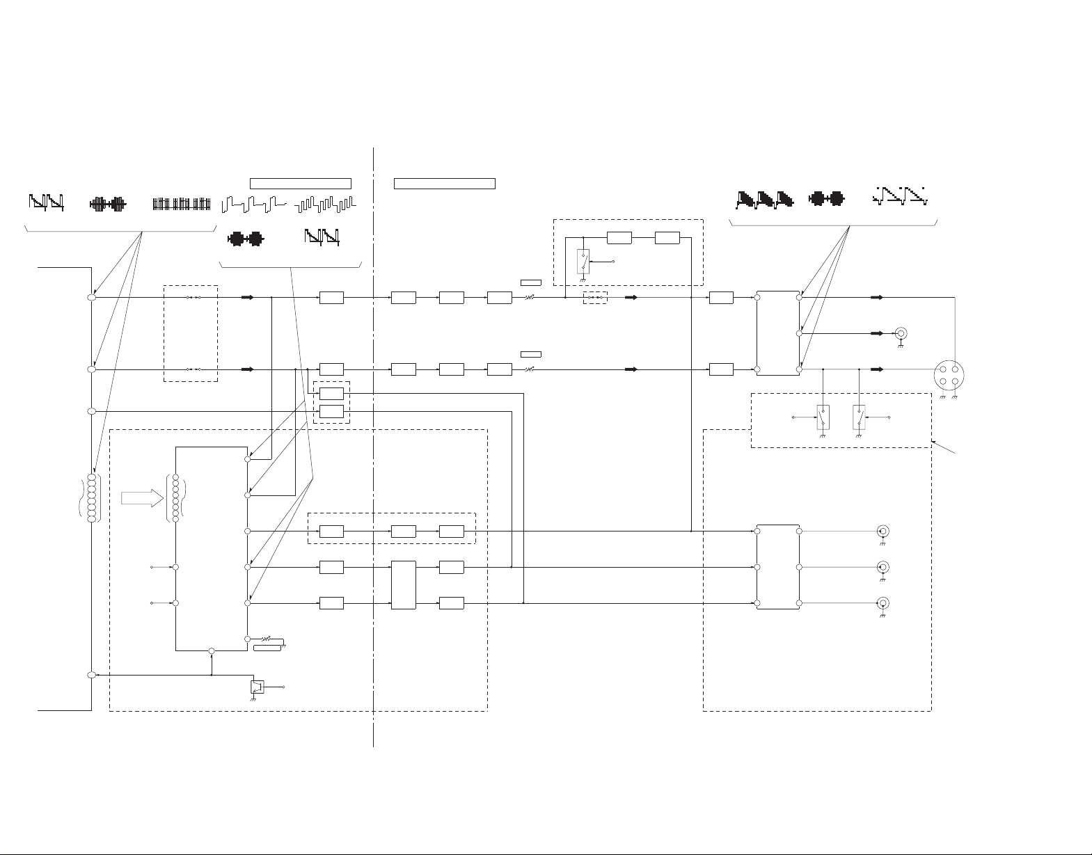
EXCEPT A112U,A115U
A115U
A112U,
EXCEPT
VGOUT
196
Q3221
Q3231
AMP
AMP
SERIES MODEL ONLY
EXCEPT A770,A360
EXCEPT A770,A360 SERIES
1.2Vp-p(20usec/div)
IC3001-201
1.5Vp-p(20usec/div)
IC3001-206
1.2Vp-p(20usec./div.)
IC3201-23
2.2Vp-p(20usec./div.)
IC3531-19
2.2Vp-p(20usec./div.)
IC3531-16
1.5Vp-p(20usec./div.)
IC3201-25
1.2Vp-p(20usec./div.)
IC3531-14
0.64Vp-p(20usec./div.)
IC3201-32
0.68Vp-p(20usec./div.)
IC3201-29
6.0Vp-p(20usec./div.)
IC3001-161 to 168
MODULE C.B.A. MOTHER C.B.A.
(AV DECORDER)
IC3001
A770,A360,SERIES MODEL ONLY
XRST
122
IC6201-79PIN
FROM
NRST
XRESET
45
VCOUT
VYOUT
C
Y
201
206
Q3211
AMP
AMP
Q3201
FL3501
B.P.F.
L.P.F.
FL3511
Q3501
AMP
AMP
Q3511
Q3502
AMP
AMP
Q3512
VR3511
VR3501
C ADJ.
Y ADJ.
A770,A360 SERIES MODEL ONLY
Q3601
AMP
Q3602
AMP
QR3601
NR
IC6201-80PIN
FROM
AMP
Q3513
AMP
Q3603
VIDEO OUT
(VIDEO DRIVER)
IC3531
14
16
19
COUT
VOUT
C
YOUT
3Y
11
VD7
VD0
168
167
166
165
164
163
162
161
(VIDEO D/A CONVERTER)
IC3201
IC6201-10PIN
FROM
SDATA
IC6201-9PIN
FROM
SCLOCK
P7
P0
SDATA
SCLOCK
20
19
9
8
7
6
5
4
3
2
CB/B ADJ
VR3201
CR/R
CB/B
Y/G
C
Y
DAC-C
DAC-B
DAC-A
DAC-F
DAC-E
38
29
32
35
23
25
ONLY
EUROPE MODEL
AMP
Q3221
AMP
Q3231
AMP
Q3241
FL3561
FL3551
B.P.F.
AMP
Q3571
AMP
Q3561
Q3551
AMP
(VIDEO AMP)
IC3581
10
13
15
7
4
2
OUTC
OUTB
OUTA
INC
INB
INA
MODEL
EXCEPT EUROPE
CR/R
CB/B
Y/G
JAPAN MODEL ONLY
QR3521 QR3522
WIDE1
IC6201-53PIN
FROM
IC6201-5PIN
FROM
WIDE2
S-VIDEO OUT
VIDEO BLOCK DIAGRAM
DV-303/DVF-5020/K5020
15
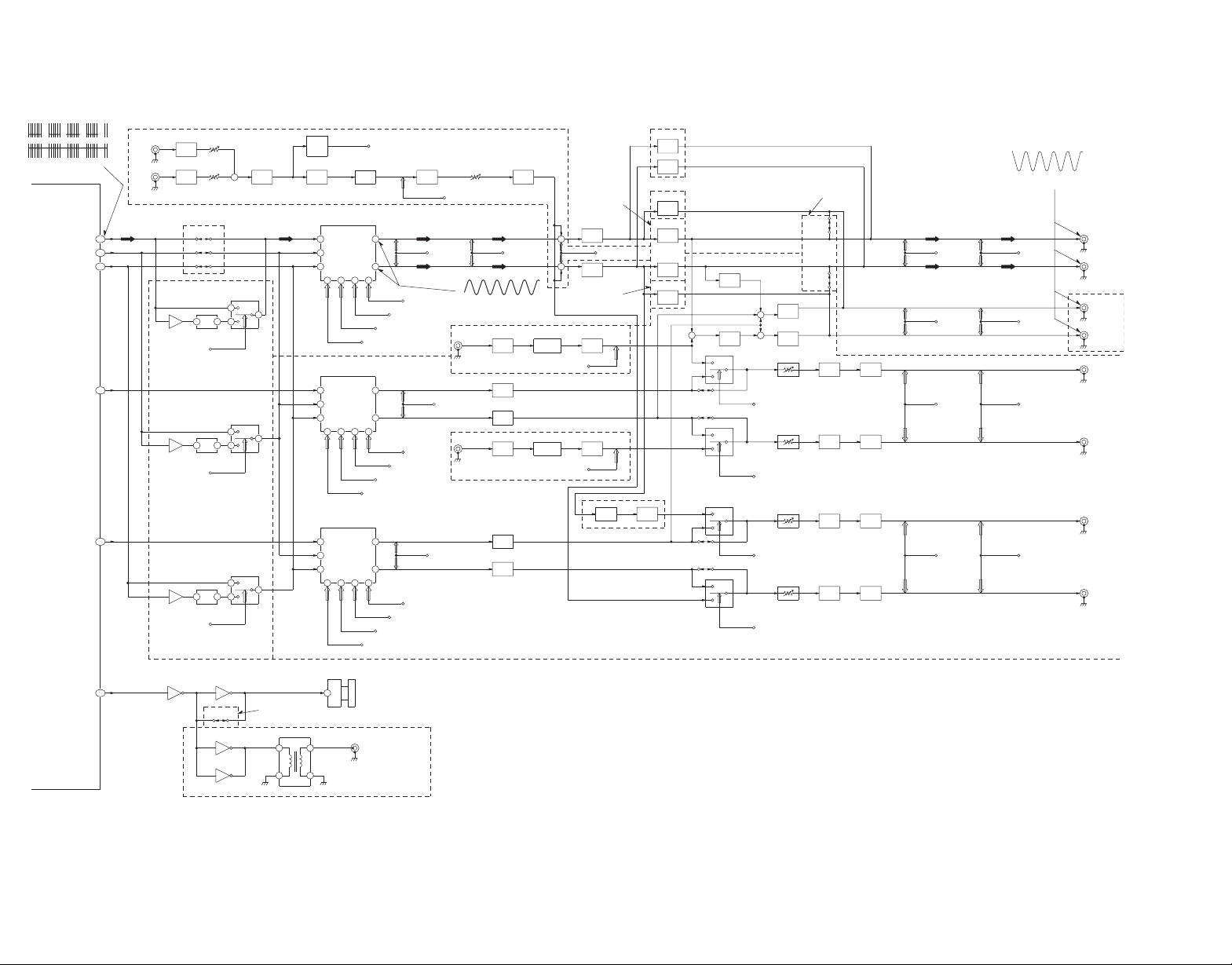
AMP
AMP
AMP AMP
AMPAMP
AMPAMP
AMPAMP
AMPAMP
AMP
AMP
AMPAMP
AMP
AMP
AMP
AMP
AMP
AMP
AMP AMP
AMPAMP
AMP
AMP
AMP
AMP
AMP
AMPAMPAMPAMP
AMP
A115 SERIES
EXCEPT A112
A270,K520 SERIES ONLY
A112,A115,A120
IC4461
IC4461
0.7Vp-p(0.5msec./div.)
0.6Vp-p(0.5msec./div.)
IC4201-13,15
6.4Vp-p(10usec./div.)
IC3001-185
A560 ONLY
T4761
A770,A560,A360,A270,A120 SERIES ONLY
K570 ONLY
3
IC4781
OPTICAL
DIGITAL AUDIO OUT
COAXIAL
DIGITAL AUDIO OUT
JK4771
6
4
3
1
IC4751
5
3
IC4751
2
6
K4751
IC4751
7
1
IC4241
4
2
IEC OUT
174
SW OUT
CNT OUT
SR OUT
SL OUT
Rch OUT
Lch OUT
FR OUT
FL OUT
2
1
IC44717IC4471
6
S4501
FROM
ATTENUATOR
IC6201-3PIN
FROM
A MUT
Q4431
IC4421
21
22
IC4392
IC4251-12PIN
FROM
K4384
SW SEL
9
15
2
1
IC4382
Q4421
IC4421
4
3
IC4392
IC4251-10PIN
FROM
10
CNT SEL
K4383
4
3
5
IC4382
S4501
FROM
ATTENUATOR
A MUT
IC6201-3PIN
FROM
S4501
FROM
ATTENUATOR
A MUT
IC6201-3PIN
FROM
2
1
Q4411
IC4401
21
22
IC4391
IC4251-12PIN
FROM
SUR SEL
K4381
9
15
2
1
IC4381
A360 SERIES
Except A770,A560,
K4442
K4441
S4501
FROM
ATTENUATOR
IC6201-3PIN
FROM
A MUT
6
7
IC4401
Q4401
4
3
IC4391
6
IC4451
7
2
IC4451
1
+
IC4441
2
1
+
7
IC4441
6
IC4251-12PIN
FROM
SUR SEL
10
K4382
4
3
5
IC4381
+
SERIES ONLY
A770,A560,A360
A360 SERIES
Except A770,A560,
A360 SERIES
Except A770,A560,
1
IC4451
2
6
IC4451
7
1
IC4306
2
7
IC4321
6
6
IC4361
7
1
IC4361
2
1
IC4605
2
EXTL
10
IC4601
17
DSP
KARAOKE
IC4341
FS MUT
SLVIR
IC4251-8PIN
FROM
K570 ONLY
K570 ONLY
IC4251-8PIN
FROM
FS MUT
SRVIR
IC4341
DSP
KARAOKE
21
IC4601
14
EXTR
6
IC4605
7
2
IC4341
1
7
IC4341
6
KARAOKE MODEL ONLY
1
IC4321
2
7
IC4691
6
+
IC6001-50PIN
FROM
MIC MUT
+
KARAOKE MODEL ONLY
ECHO MUT
IC6001-49PIN
FROM
7
IC4306
6
VR4952
1
9
2
IC4952
2
IC6001-51PIN
TO
VOICE DET
IC4951
AMP
ECHO
DET
LEVEL
MIC
7
6
IC4952
1
2
IC4691
+
VR4692
7
5
IC4671
MIC2
VR4691
1
3
IC4671
MIC1
NRST
IC6201-79PIN
FROM
SBO1
IC6201-72PIN
FROM
SBT1
IC6201-70PIN
FROM
SW
STBDAC
CNT
13
16
IC6201-59PIN
FROM
(AUDIO D/A CONVERTER)
IC4221
28272622
IC4251-9PIN
FROM
DACMUT
1
3
2
IC4251-7PIN
FROM
10
DSPTHURU
IC4602
3
1
3
4
2
IC4612
42
IC4601
45
AOUT2
183
A770,A560,A360 SERIES ONLY
NRST
IC6201-79PIN
FROM
SBO1
IC6201-72PIN
FROM
SBT1
IC6201-70PIN
FROM
SR
STBDAC
SL
13
16
IC6201-59PIN
FROM
(AUDIO D/A CONVERTER)
IC4211
28272622
IC4251-9PIN
FROM
DACMUT
1
3
2
IC6001-75PIN
FROM
GAIN SEL
DACMUT
IC4251-9PIN
FROM
NRST
IC6201-79PIN
FROM
SBO1
IC6201-72PIN
FROM
SBT1
IC6201-70PIN
FROM
IC6201-59PIN
FROM
STBDAC
FR
FL
13
16
(AUDIO D/A CONVERTER)
IC4201
28272622
1
3
2
IC4251-7PIN
FROM
9
DSPTHURU
IC4602
4
5
5
6
3
IC4612
41
IC4601
44
IC4251-7PIN
FROM
DSPTHURU
11
IC4602
14
13
124043
IC4601IC4612
8
9
A360 SERIES
Except A770,A560,
K4203
K4201
K4202
AOUT1
184
179
LRCK
SRCK
181
IC3001
AOUT0
185
16
DV-303/DVF-5020/K5020
AUDIO BLOCK DIAGRAM
DV-303/DVF-5020/K5020
CIRCUIT DESCRIPTION
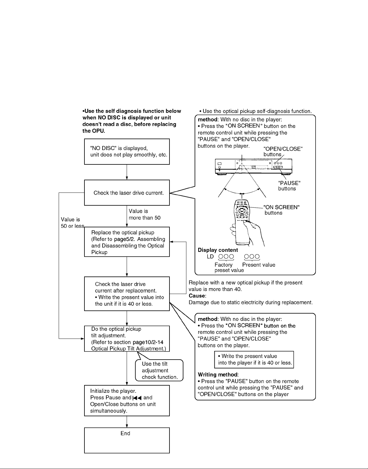
1. Optical Pickup Self-Diagnosis and Replacement Procedure
The optical pickup self-diagnosis function and tilt adjustment check function have been newly added to this player. When
repairing, use the following procedure for effective Self-diagnosis and tilt adjustment.
Be sure to use the self-diagnosis function before replacing the optical pickup when "NO DISC" is displayed. As a guideline, you
should replace the optical pickup when the value of the laser drive current is more than 50.
Note
Press the power button to turn on the power, and check the value before the unit warms up (within three minutes).
17
DV-303/DVF-5020/K5020
CIRCUIT DESCRIPTION
2. Self-Diagnosis Function and Service Modes
2-1 Service Mode Table
The service modes can be activated by pressing various button combinations on the player and remote control unit.
Player Remote control
buttons unit buttons
0 Displaying the UHF display F_ _ _ Refer to spage18/2-2 Self-
5 Tilt adjustment Refer to
PAUSE 6 Checking the region numbers and broadcast system
+ 7 Checking the program version Check the IC6302
OPEN/CLOSE FLASH ROM program.
9 Lighting Confirmation Fanction of Display Tube
ON SCREEN Checking the laser drive current Refer to page17/1.
PAUSE Writing the laser drive current value after replacing
the optical pickup (do not use for anything other than
optical pickup replacement)
PAUSE Initializing the DVD player Refer to page20/4-1
4 (restoring factory preset settings) Initializing the DVD Player
OPEN/CLOSE *Use when replaceing a microprocessor, microprocessor
peripheral parts, or C.B.A.
Application Note
Diagnosis Function (UHF
Display).
Optical Pickup Tilt
Adjustment.
Optical Pickup
Self-Diagnosis and
Replacement Procedure.
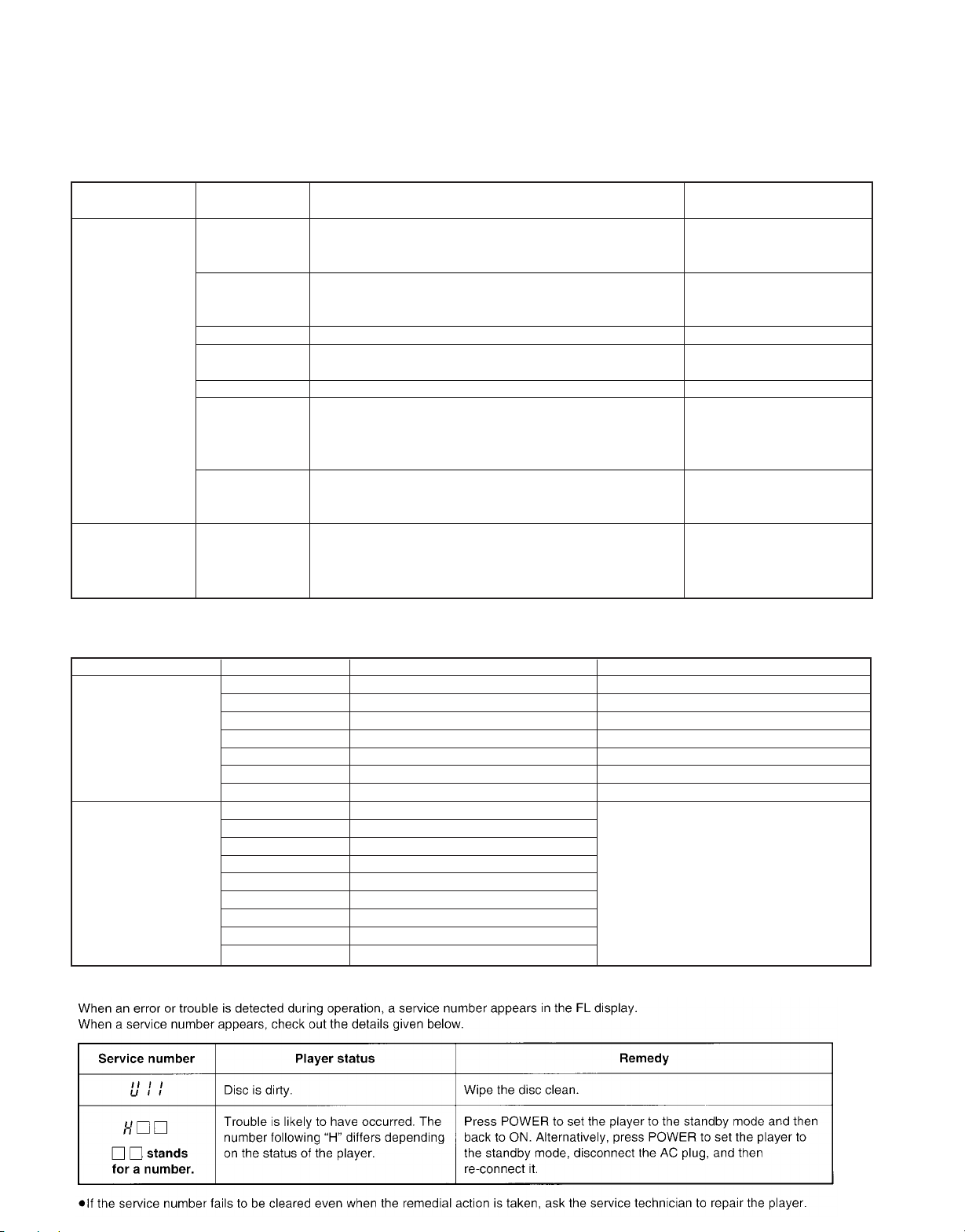
2-2 Self-Diagnosis Function (UHF Display)
This unit incorporates a convenient self-diagnosis function for use in troubleshooting.
Display method Display Diagnosis Checkpoints
Service numbers U11 Focus error IC2001,IC2511,IC5201,pickup
displayed H01 Tray loading error IC2001, IC2511, loading motor
during use H02 Spindle servo error Spindle motor, IC2501, IC2001
H03 Traverse error Stepping motor, IC2511, IC2001
H04 Tracking servo error IC2001, IC2501, IC5201, pickup, disc
H05 Seek error Stepping motor, IC2511, IC2001
H06 Power supply error IC1021, IC1121, IC1151, IC6001
Press the "0" button
on the remote control
unit while pressing
the "PAUSE" and
"OPEN/CLOSE"
button on the player.
F0** Disc format error
F1** Disc code error
F2** Decoder LSI error
F3** SDRAM error
F4** IIC BUS error
F5** DSC
F6** ECC error
F7** Microprocessor error
F8** Microprocessor error
If this type of error occurs, refer to
page19/2-4 Examples of Repairs Using
Error Codes.
2-3 Self-Diagnosis Display Function
18
DV-303/DVF-5020/K5020
CIRCUIT DESCRIPTION
2-4 Examples of Repairs Using Error Codes
Refer to this section when carrying out repairs.
Error display Malfunction example
F0** Disc, IC7001
F103 Disc, IC7001
F4FF IC6001
F500 Optical pickup, IC2001, IC5201, IC2511, IC2501
F501 IC2001, IC6201
F502 IC2501, IC2511, IC2001, IC5202
F504 IC5202, IC2001
F505 Disc, IC2501, IC2511, IC5202, IC2001
F506 Disc, Optical pickup, IC2001
F600 Disc, IC7001, IC5202, IC2001
F601 Disc, IC7001
F602 Disc, IC5202, IC2001
F603 Disc, IC5202, IC2001
F610 IC7001
F611 IC7001, IC5202, IC2001
F612 IC7001, IC15202, IC2001
F620 Laser drive circuit
F621 Laser drive circuit
F700 IC6201
F701 IC6201
F702 IC6201
F880 IC6201
F890 IC6201
F891 IC6201
F8A0 IC6201
F893 IC6302
F894 IC6303
2-5 Sales Demonstration Lock Function
This function prevents discs from being lost when the unit is used for sales demonstrations, by disabling the disc eject function.
"LOCKED" is displayed on the unit, and ordinary operation is disabled.
2-5-1 Setting Method
The sales demonstration lock function is set by simultaneously pressing the "POWER" button of DVD Player on the remote
control unit and the "STOP" button on the main unit. ("LOCKED" is displayed when the lock function is engaged.)
2-5-2 Release Method
The function can be released using the same procedure as for setting. If the remote control unit is not at hand, the function can
be released by using the same method as for player initialization (pressing the "PAUSE," "4" and "OPEN/CLOSE" buttons
simultaneously).
19
DV-303/DVF-5020/K5020
CIRCUIT DESCRIPTION
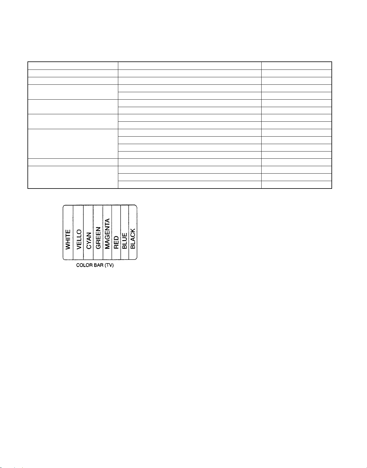
3. Service Tools and Equipment
3-1 Service Tools and Equipment Table
Application Name Number
General DVD disc (Include the color bar 75%)
Tilt adjustment Hex wrench (ø1.27mm)
Inspection Extension cables (power supply C.B.A. to mother C.B.A.) Extension cable(A)
Extension cable (module C.B.A. to mother C.B.A.) Extension cable(B)
Others Screw lock
Grease 410-0013-05
Confirmation CD disc
VCD disc
Electrical adjustment Oscilloscope
Probe
AV cable
TV monitor
General General tools (Screw driver. etc)
Static electricity countermeasures Soldering iron (with ESD countermeasure)
Anti-static wrist strap
Conductive material (conductive sheet)
DVD disc (Include 75% color bar)
3-2 Storing and Handling DVD Discs
Surface precision is vital for DVD discs. Be sure to store and handle them carefully.
1. Do not place discs directly onto the workbench, etc., after use.
2. Handle discs carefully in order to maintain their flatness.
Place them into their case after use and store them vertically. Store discs in a cool place where they are not exposed to
direct sunlight or air from air conditioners.
3. Accurate adjustment will not be possible if the disc is warped from being placed on a surface made of glass, etc. If this
happens, use a new test disc to make optical adjustments.
4. If adjustment is done using a warped disc, the adjustment will be incorrect and some discs will not be playable.
4. Service Precautions
4-1 Initializing the DVD Player
Initialize the DVD player whenever you replace a microprocessor, microprocessor peripheral parts, module C.B.A or mother
C.B.A.
4-1-1Precautions
The customer settings will return to factory preset settings when the player is initialized. Make a note of the settings and reset
them after initializing.
When resetting, see the Initial Settings in the Operating Instructions.
4-1-2 Initialization Method
The player will be initialized (return to the factory preset condition) when you press the "PAUSE", "4" and "OPEN/CLOSE"
buttons simultaneously. When the DVD player is initialized, "All Clear" appears on screen, it also displays "INITIALIZE".
20
DV-303/DVF-5020/K5020
ADJUSTMENT
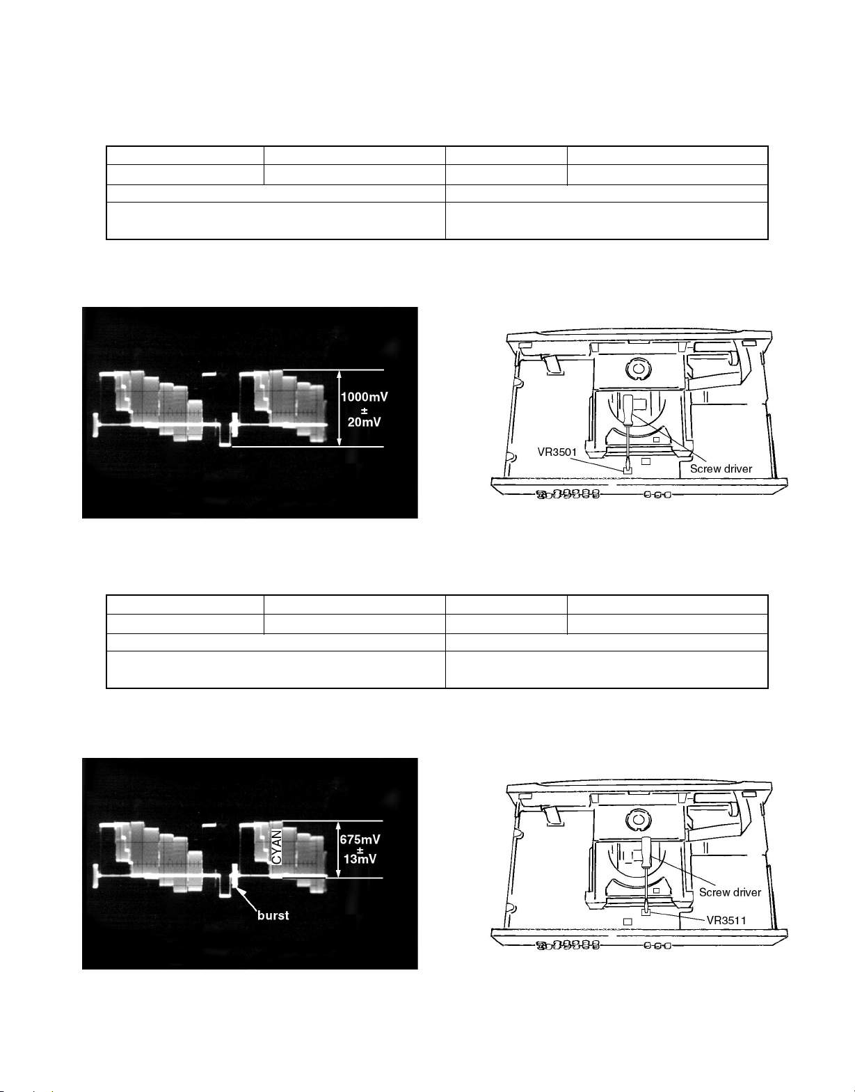
1. Video Output (Luminance Signal) Adjustment
Do this adjustment after replacing a C.B.A.
Measurement point Adjustment point Mode Disc
Video output terminal VR3501 (mother C.B.A.) Color bar 75% DVD disc (Color bar 75%)
Measuring equipment, tools Adjustment value
Screwdriver, Oscilloscope 1000mVp-p±20mV
200mV/div, 10µsec/div
Purpose: To maintain video signal output compatibility.
1. Connect the oscilloscope to the video output terminal and terminate at 75 ohms.
2. Adjust VR3501 so that the luminance signal (Y+S) level becomes 1000 mVp-p±20 mV.
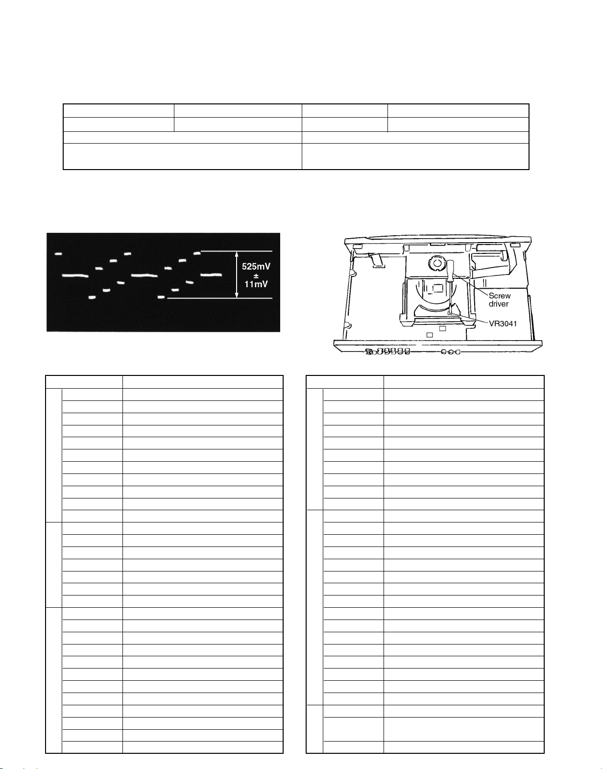
2. Video Output (Chrominance Signal) Adjustment
Do this adjustment after replacing a C.B.A.
Measurement point Adjustment point Mode Disc
Video output terminal VR3511 (mother C.B.A.) Color bar 75% DVD disc (Color bar 75%)
Measuring equipment, tools Adjustment value
Screwdriver, Oscilloscope 675mVp-p±13mV
200mV/div, 10µsec/div
Purpose: To maintain video signal output compatibility.
1. Connect the oscilloscope to the video output terminal and terminate at 75 ohms.
2. Adjust VR3511 so that the chrominance signal (C) level becomes 675 mVp-p±13 mV.
21
DV-303/DVF-5020/K5020
ADJUSTMENT/ABBREVIATION
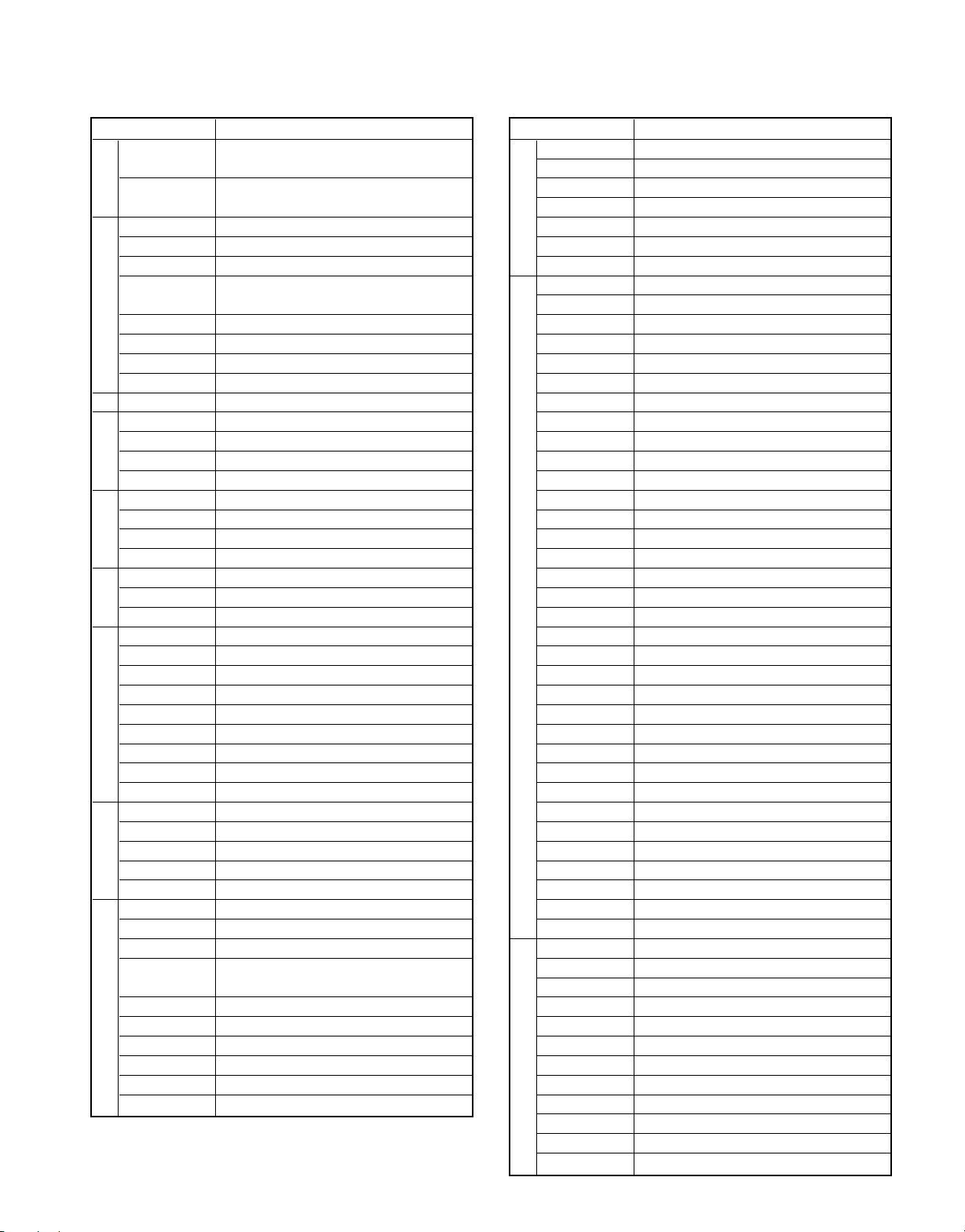
3. Video Component Signal (CB) Output Adjustment
Do this adjustment after replacing a C.B.A.
Measurement point Adjustment point Mode Disc
Video output terminal VR3041 (mother C.B.A.) Color bar 75% DVD disc (Color bar 75%)
Measuring equipment, tools Adjustment value
Screwdriver, Oscilloscope 525mVp-p±11mV
100mV/div, 10µsec/div
Purpose: To maintain video signal output compatibility.
1. Connect the oscilloscope to the video component output terminal and terminate at 75 ohms.
2. Apply the trigger at the Y output terminal signal.
3. Adjust VR3041 so that the video component signal (CB) level becomes 525 mVp-p ±11 mV.
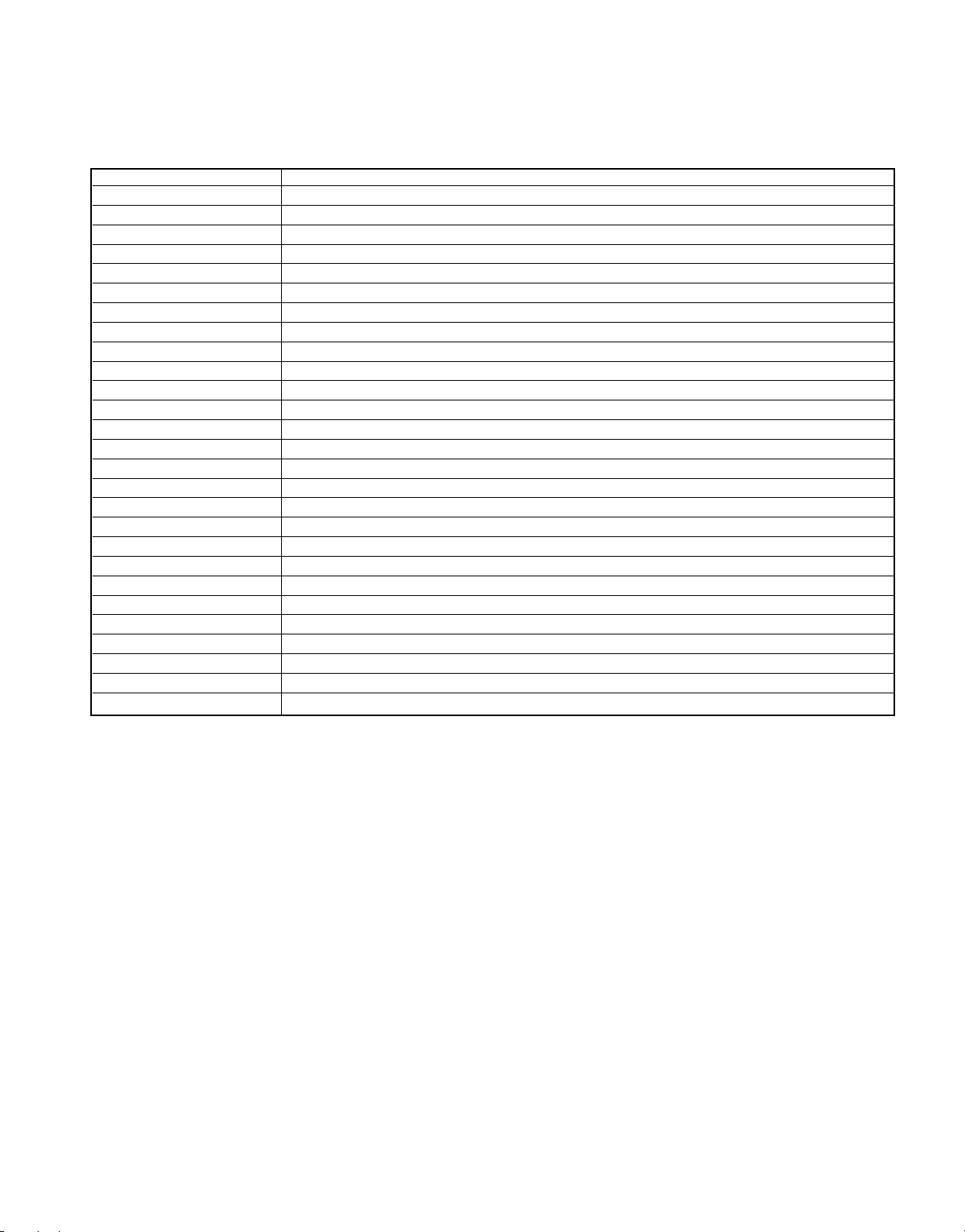
4. Abbreviations
INITIAL/LOGO ABBREVIATIONS
A A0~UP ADDRESS
ACLK AUDIO CLOCK
AD0~UP ADDRESS BUS
ADATA AUDIO PES PACKET DATA
ALE ADDRESS LATCH ENABLE
AMUTE AUDIO MUTE
AREQ AUDIO PES PACKET REQUEST
ARF AUDIO RF
ASI SERVO AMP INVERTED INPUT
ASO SERVO AMP OUTPUT
ASYNC AUDIO WORD DISTINCTION SYNC
B BCK BIT CLOCK (PCM)
BCKIN BIT CLOCK INPUT
BDO BLACK DROP OUT
BLKCK SUB CODE BLOCK CLOCK
BOTTOM CAP. FOR BOTTOM HOLD
BYP BYPATH
BYTCK BYTE CLOCK
C CAV CONSTANT ANGULAR VELOCITY
CBDO CAP. BLACK DROP OUT
CD COMPACT DISC
CDSCK CD SERIAL DATA CLOCK
CDSRDATA CD SERIAL DATA
CDRF CD RF (EFM) SIGNAL
CDV COMPACT DISC-VIDEO
CHNDATA CHANNEL DATA
CKSL SYSTEM CLOCK SELECT
CLV CONSTANT LINEAR VELOCITY
COFTR CAP. OFF TRACK
22
CPA CPU ADDRESS
INITIAL/LOGO ABBREVIATIONS
C CPCS CPU CHIP SELECT
CPDT CPU DATA
CPUADR CPU ADDRESS LATCH
CPUADT CPU ADDRESS DATA BUS
CPUIRQ CPU INTERRUPT REQUEST
CPRD CPU READ ENABLE
CPWR CPU WRITE ENABLE
CS CHIP SELECT
CSYNCIN COMPOSITE SYNC IN
CSYNCOUT COMPOSITE SYNC OUT
D DACCK D/A CONVERTER CLOCK
DEEMP DEEMPHASIS BIT ON/OFF
DEMPH DEEMPHASIS SWITCHING
DIG0~UP FL DIGIT OUTPUT
DIN DATA INPUT
DMSRCK DM SERIAL DATA READ CLOCK
DMUTE DIGITAL MUTE CONTROL
DO DROP OUT
DOUT0~UP DATA OUTPUT
DRF DATA SLICE RF (BIAS)
DRPOUT DROP OUT SIGNAL
DREQ DATA REQUEST
DRESP DATA RESPONSE
DSC DIGITAL SERVO CONTROLLER
DSLF DATA SLICE LOOP FILTER
DVD DIGITAL VIDEO DISC
E EC ERROR TORQUE CONTROL
ECR ERROR TORQUE CONTROL
REFERENCE
ENCSEL ENCODER SELECT
DV-303/DVF-5020/K5020
ABBREVIATION
INITIAL/LOGO ABBREVIATIONS
E ETMCLK EXTERNAL M CLOCK
(81MHz/40.5MHz)
ETSCLK EXTERNAL S CLOCK
(54MHz)
F FBAL FOCUS BALANCE
FCLK FRAME CLOCK
FE FOCUS ERROR
FFI FOCUS ERROR AMP INVERTED
INPUT
FEO FOCUS ERROR AMP OUTPUT
FG FREQUENCY GENERATOR
FSC FREQUENCY SUB CARRIER
FSCK FS (384 OVER SAMPLING) CLOCK
G GND COMMON GROUNDING (EARTH)
H HA0~UP HOST ADDRESS
HD0~UP HOST DATA
HINT HOST INTERRUPT
HRXW HOST READ/WRITE
I IECOUT IEC958 FORMAT DATA OUTPUT
IPFRAG INTERPOLATION FLAG
IREF I (CURRENT) REFERENCE
ISEL INTERFACE MODE SELECT
L LDON LASER DIODE CONTROL
LPC LASER POWER CONTROL
LRCK L CH/R CH DISTINCTION CLOCK
M MA0~UP MEMORY ADDRESS
MCK MEMORY CLOCK
MCKI MEMORY CLOCK INPUT
MCLK MEMORY SERIAL COMMAND CLOCK
MDATA MEMORY SERIAL COMMAND DATA
MDQ0~UP MEMORY DATA INPUT/OUTPUT
MDQM MEMORY DATA I/O MASK
MLD MEMORY SERIAL COMMAND LOAD
MPEG MOVING PICTURE EXPERTS GROUP
O ODC OPTICAL DISC CONTROLLER
OFTR OFF TRACKING
OSCI OSCILLATOR INPUT
OSCO OSCILLATOR OUTPUT
OSD ON SCREEN DISPLAY
P P1~UP PORT
PCD CD TRACKING PHASE DIFFERENCE
PCK PLL CLOCK
PDVD DVD TRACKING PHASE
DIFFERENCE
PEAK CAP. FOR PEAK HOLD
PLLCLK CHANNEL PLL CLOCK
PLLOK PLL LOCK
PWMCTL PWM OUTPUT CONTROL
PWMDA PULSE WAVE MOTOR DRIVE A
PWMOA, B” PULSE WAVE MOTOR OUT A, B”
INITIAL/LOGO ABBREVIATIONS
R RE READ ENABLE
RFENV RF ENVELOPE
RFO RF PHASE DIFFERENCE OUTPUT
RS (CD-ROM) REGISTER SELECT
RSEL RF POLARITY SELECT
RST RESET
RSV RESERVE
S SBI0, 1 SERIAL DATA INPUT
SBO0 SERIAL DATA OUTPUT
SBT0, 1 SERIAL CLOCK
SCK SERIAL DATA CLOCK
SCKR AUDIO SERIAL CLOCK RECEIVER
SCL SERIAL CLOCK
SCLK SERIAL CLOCK
SDA SERIAL DATA
SEG0~UP FL SEGMENT OUTPUT
SELCLK SELECT CLOCK
SEN SERIAL PORT ENABLE
SIN1, 2 SERIAL DATA IN
SOUT1, 2 SERIAL DATA OUT
SPDI SERIAL PORT DATA INPUT
SPDO SERIAL PORT DATA OUTPUT
SPEN SERIAL PORT R/W ENABLE
SPRCLK SERIAL PORT READ CLOCK
SPWCLK SERIAL PORT WRITE CLOCK
SQCK SUB CODE Q CLOCK
SQCX SUB CODE Q DATA READ CLOCK
SRDATA SERIAL DATA
SRMADR SRAM ADDRESS BUS
SRMDT0~7 SRAM DATA BUS 0~7
SS START/STOP
STAT STATUS
STCLK STREAM DATA CLOCK
STD0~UP STREAM DATA
STENABLE STREAM DATA INPUT ENABLE
STSEL STREAM DATA POLARITY SELECT
STVALID STREAM DATA VALIDITY
SUBC SUB CODE SERIAL
SBCK SUB CODE CLOCK
SUBQ SUB CODE Q DATA
SYSCLK SYSTEM CLOCK
T TE TRACKING ERROR
TIBAL BALANCE CONTROL
TID BALANCE OUTPUT 1
TIN BALANCE INPUT
TIP BALANCE INPUT
TIS BALANCE OUTPUT 2
TPSN OP AMP INPUT
TPSO OP AMP OUTPUT
TPSP OP AMP INVERTED INPUT
TRCRS TRACK CROSS SIGNAL
TRON TRACKING ON
TRSON TRAVERSE SERVO ON
23
DV-303/DVF-5020/K5020
ABBREVIATION/VOLTAGE CHART
INITIAL/LOGO ABBREVIATIONS
V VBLANK V BLANKING
VCC COLLECTOR POWER SUPPLY
VOLTAGE
VCDCONT VIDEO CD CONTROL (TRACKING
BALANCE)
VDD DRAIN POWER SUPPLY VOLTAGE
VFB VIDEO FEED BACK
VREF VOLTAGE REFERENCE
VSS SOURCE POWER SUPPLY VOLTAGE
W WAIT BUS CYCLE WAIT
WDCK WORD CLOCK
WEH WRITE ENABLE HIGH
WSR WORD SELECT RECEIVER
X X X'TAL
XALE X ADDRESS LATCH ENABLE
XAREQ X AUDIO DATA REQUEST
XCDROM X CD ROM CHIP SELECT
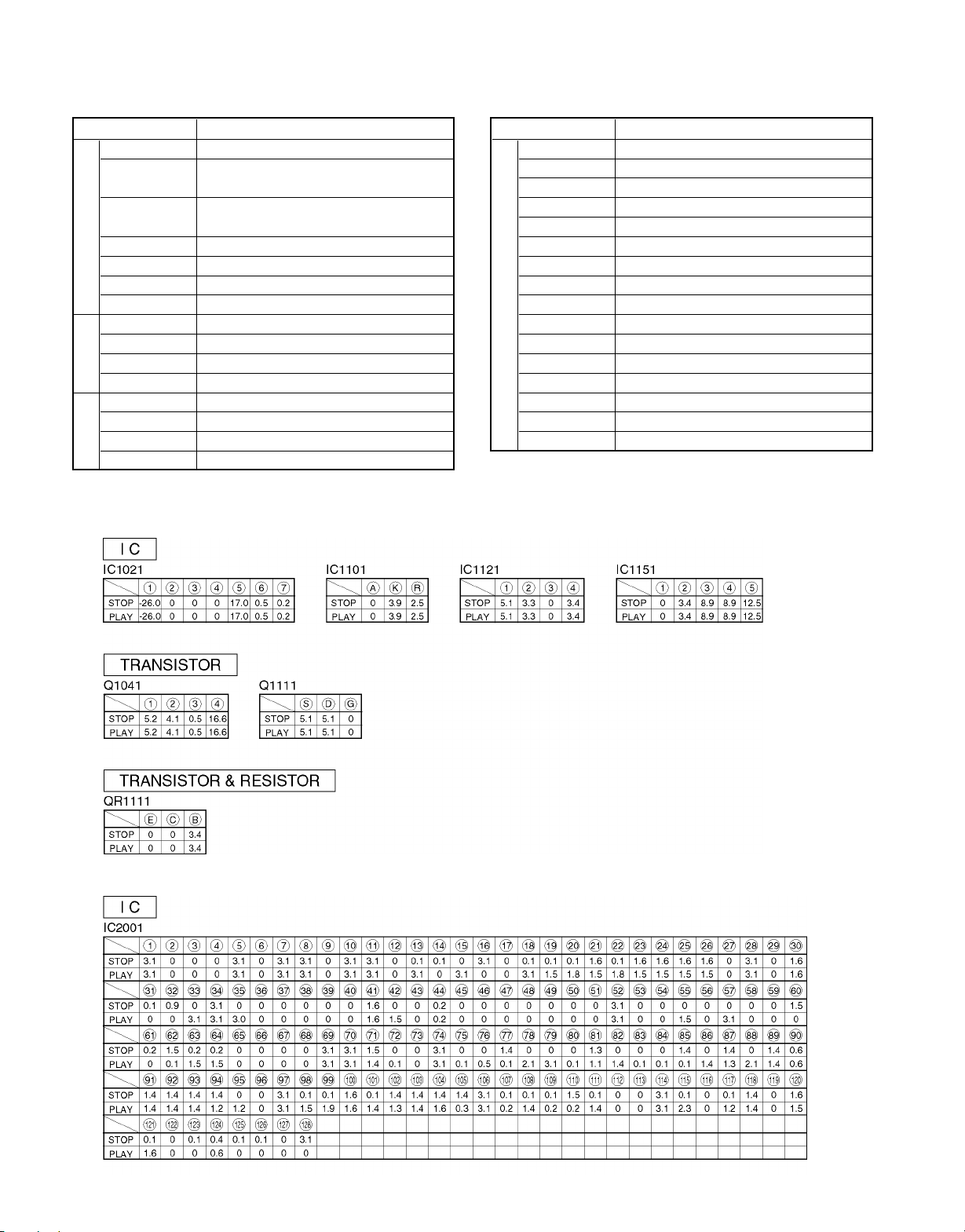
5. VOLTAGE CHART
5-1 POWER SUPPLY C.B.A.
INITIAL/LOGO ABBREVIATIONS
X XCS X CHIP SELECT
XCSYNC X COMPOSITE SYNC
XDS X DATA STROBE
XHSYNCO X HORIZONTAL SYNC OUTPUT
XHINT XH INTERRUPT REQUEST
XI X'TAL OSCILLATOR INPUT
XINT X INTERRUPT
XMW X MEMORY WRITE ENABLE
XO X'TAL OSCILLATOR OUTPUT
XRE X READ ENABLE
XSRMCE X SRAM CHIP ENABLE
XSRMOE X SRAM OUTPUT ENABLE
XSRMWE X SRAM WRITE ENABLE
XVCS X V-DEC CHIP SELECT
XVDS X V-DEC CONTROL BUS STROBE
XVSYNCO X VERTICAL SYNC OUTPUT
5-2 MODULE C.B.A.
24
 Loading...