

Kenwood DV-203, DV-2070, DVF-5010, DVF-9010, DVF-K-7010 Service manual
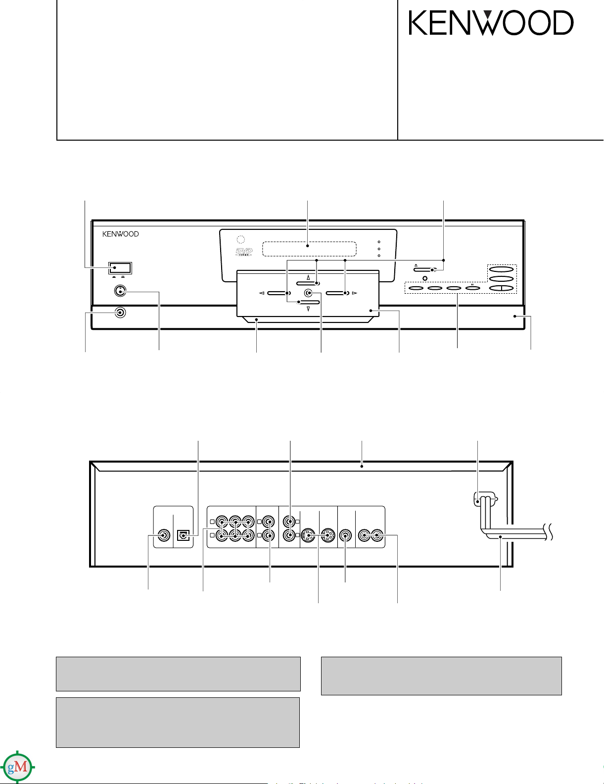
CD/VIDEO-CD/DVD PLAYER
PHONES LEVEL
MAXMIN
PHONES
ON SCREEN
PANEL UP / DOWN
RETURN
3
7
4¢
OPEN/CLOSE
DVD MENU
ENTER
1¡
VIRTUAL
SURROUND
96 kfs
DTS
ON OFF
POWER
COMPONENT VIDEO OUTPUT
Y
Cb Cr
(PCM/BIT STREAM)
COAXIAL OPTICAL
DIGITAL OUTPUT
CENTER
S-VIDEO 1
VIDEO OUTPUT
MIX LINE
OUTPUT
S-VIDEO 2
FRONT SURROUND SUBWOOFER
6CH. OUTPUT
L
R
L
R
1
2
DV-203/2070
DVF-5010/9010/K7010
SERVICE MANUAL
© 1998-8/B51-5456-00 (K/K) 3486
Knob(BUTTON)
(K27-2300-04)
Phone jack
(E11-0190-05)
Knob
(K29-7431-04)
Oscillating module
(W02-1114-05)
Escutcheon
(B07-2420-12)
Phono jack
(E63-1060-05)
Front glass *
(B10-)
Knob
(K29-7358-04)
Dressing panel
(A21-3693-13)
Metallic cabinet
(A01-3625-01)
Knob
(K29-7355-04)x5
Knob
(K29-7356-03)
Power cord bushing
(J42-0083-05)
Sub panel
(A22-1809-01)
Phono jack
Phono jack
(E63-1059-05)
Phono jack
(E63-1063-05)
(E63-0175-05)
In compliance with Federal Regulations, following are reproductions of labels on, or inside the product relating to laser product
safety.
KENWOOD-Crop. certifies this equipment conforms to DHHS
Regulations No. 21 DFR 1040. 10, Chapter 1, Subchapter J.
DANGER : Laser radiation when open and interlock defeated.
AVOID DIRECT EXPOSURE TO BEAM
Phono jack
(E63-1061-05)
Cylindrical receptacle
(E56-0021-05)x2
Caution : No connection of ground line if disassemble the
NOTE : Please replace the mechanism PCB
AC power cord*
Phono jack
(E30-)
(E63-1057-05)
Illust. is DVF-9010.
* Refer to parts list on page 52.
unit. Please connect the ground line on rear
panel, PCBs, Chassis and some others.
(W02-266x-05) with new one, if it is
malfunction.
Audio
(E30-0505-05) (E30-2725-05) (E30-1427-05) (B19-1529-05)
(E03-0115-05)
(A70-1229-05) : DVF-K7010
(A70-1230-05) : DV-203/DVF-5010
(A70-1227-05) :
DV-2070/DVF-9010
Battery cover (A09-1105-05)
Battery cover
(A09-1124-08)
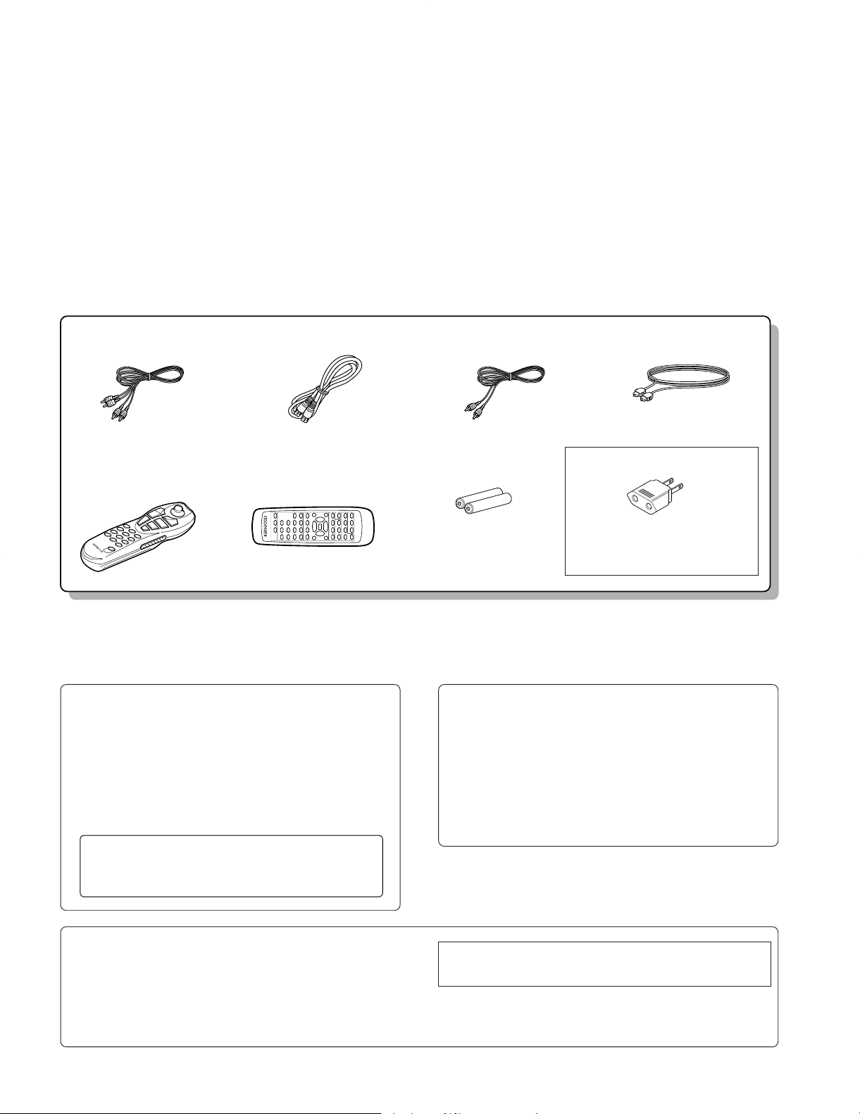
cord (Red, White) ......(3)
Remote control unit .............(1)
Batteries (R6/AA) ........(2)
Optical fiber cable............. (1)
S-VIDEO cord ......................(1) Video cord (Yellow) .............(1)
AC plug adaptor ............. (1)
Use to adapt the plug on the power cord
to the shape of the wall outlet.
(Accessory only for regions where
use is necessary.)
Remote control unit............. (1)
Beware of condensation
When the difference between the internal temperature of the unit and
external atmosphere is large, dew (mist) may be produced on the
internal parts of the unit. In such a case, turn the unit ON and leave
it for a few hours until the condensation has dried up.
Be especially careful in the following conditions:
When the unit is brought into a place where there is a large difference
in temperature between the previous location, when the humidity of
the listening room is high, etc.
Note related to transportation and
movement
Before transporting or moving this unit, carry out the following
operations.
1. Set the POWER key to ON without loading a disc.
2. Wait a few seconds and verify that the display shown appears.
3. Set the POWER key to OFF.
Operation to reset
The microprocessor may fall into malfunction (impossibility to operate
erroneous display, etc.) when the power cord is unplugged while power
is ON or due to an external factor. In this case, execute the following
procedure to reset the microprocessor and return it to normal condition.
÷ Please note that resetting the microprocessor clears the contents
stored in, it returns the microprocessor to the condition when it left
the factory.
While holding the 7 key, press and hold the 8 key until “INITIAL OK!”
appears.
DV-203/2070/DVF-5010/9010/K7010
CONTENTS / ACCESSORIES
Contents
CONTENTS / ACCESSORIES ....................................2
CONTROLS.................................................................3
DISASSEMBLY FOR REPAIR.....................................6
BLOCK DIAGRAM.....................................................11
CIRCUIT DESCRIPTION...........................................13
ADJUSTMENT.......................................................... 24
WIRING DIAGRAM....................................................26
Accessories
PARTS DESCRIPTIONS...........................................27
PC BOARD ................................................................28
SCHEMATIC DIAGRAM............................................33
EXPLODED VIEW .....................................................49
PARTS LIST...............................................................52
SPECIFICATIONS.....................................................67
Cautions
DVD VCD CD
P.B.C. DOLBY DIGITAL RANDOM PROG.
TITLE CHAPTER TRACK CD TEXT
ANGLE REPEAT ALL
A B
STEREO
LR
KARAOKE
NO DISC
2
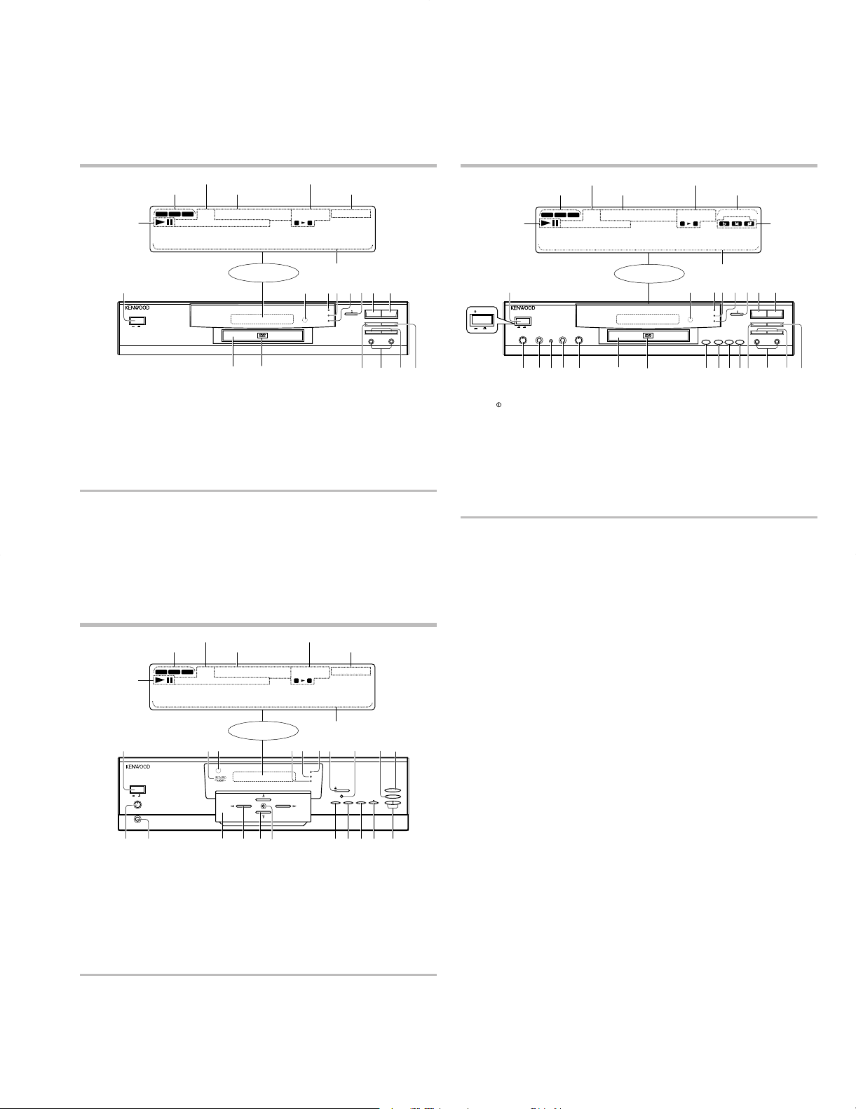
Display / Main unit (DVF-5010)
L, STEREO, R indicators
Character information display
Operation indicators
3 :Play
8 :Pause
DVD, VCD, CD indicators
Special playback related indicators
Standby mode of the unit
While the POWER key is set to ON, this unit can be put to the standby mode using the graphical remote control unit provided
with a KENWOOD AUDIO VIDEO SURROUND RECEIVER. When the STANDBY indicator of this unit is lit, a small amount of
current flows in it to back up the internal memory. This status is referred to as the standby mode.
Display
VCD and CD related indicators
DVD related indicators
1
POWER key
2
Remote control sensor
3
VIRTUAL SURROUND indicator
Lights during playback of an AC-3 5.1-channel disc by setting virtual
surround.
4
96 kfs indicator
Lights during playback of a DVD LPCM disc with 96 kfs sampling
frequency.
5
DTS indicator
Lights during playback of a DVD DTS disc.
6
Open/close (0) key
7
Stop (7) key
8
Play (3) key
9
Tray panel
0
DVD badge
!
REPEAR key
@
Manual search (1,
¡
) keys
#
Skip down (4) / up (¢) keys
$
Pause (8) key
Display / Main unit (DVF-K7010)
L, STEREO, R indicators
Character information display
Operation indicators
3 :Play
8 :Pause
DVD, VCD, CD indicators
Special playback related indicators
Standby mode of the unit
While the POWER key is set to ON, this unit can be put to the standby mode using the graphical remote control unit provided
with a KENWOOD AUDIO VIDEO SURROUND RECEIVER. When the STANDBY indicator of this unit is lit, a small amount of
current flows in it to back up the internal memory. This status is referred to as the standby mode.
Displa
y
VCD and CD related indicators
DVD related indicators
1 POWER ( POWER) key
2 Remote control sensor
3 VIRTUAL SURROUND indicator
Lights during playback of an AC-3 5.1-channel disc by setting virtual
surround.
4 96 kfs indicator
Lights during playback of a DVD LPCM disc with 96 kfs sampling
frequency.
5 DTS indicator
Lights during playback of a DVD DTS disc.
6 Open/close (0) key
7 Stop (7) key
8 Play (3) key
9 MIC 1 VOLUME control
0 MIC 1 jack
! MIC CONTROL jack
@ MIC 2 jack
# MIC 2 VOLUME control
$ Tray panel
% DVD badge
^ KARAOKE key
& Flat ( ) keyI
i
È
* Natural ( ) key
( Sharp ( ) key
) REPEAT key
¡ Manual search (1, ¡) keys
™ Skip down (4) / up (¢) keys
£ Pause (8) key
KARAOKE indicators
*The key name
indications on the
unit are variable
depending on the
area where it is
marketed.
Ii
Control and Indication
PHONES LEVEL
MAXMIN
PHONES
ON SCREEN
PANEL UP / DOWN
RETURN
3
7
4¢
OPEN/CLOSE
DVD MENU
ENTER
1¡
VIRTUAL
SURROUND
96 kfs
DTS
ON
OFF
POWER
DVD VCD CD
P.B.C. DOLBY DIGITAL RANDOM PROG.
STEREO
ANGLE
PCM
REPEAT ALL
KARAOKE
LR
TITLE CHAPTER TRACK CD TEXT
A B
•••••••••••••••
¡
!
@
# $%
*(^&
)
7
3
1
2
0
9
654
8
Display / Main unit (DVF-9010)
L, STEREO, R indicators
Character information display
Operation indicators
3 :Play
8 :Pause
DVD, VCD, CD indicators
Special playback related indicators
Standby mode of the unit
While the POWER key is set to ON, this unit can be put to the standby mode using the graphical remote control unit provided
with a KENWOOD AUDIO VIDEO SURROUND RECEIVER. When the STANDBY indicator of this unit is lit, a small amount of
current flows in it to back up the internal memory. This status is referred to as the standby mode.
Display
VCD and CD related indicators
DVD related indicators
1
POWER key
2
DVD indicator
Lights up when a DVD disc is loaded.
3
Remote control sensor
4
DTS indicator
Lights during playback of a DTS-encoded DVD disc.
5
96 kfs indicator
Lights during playback of a DVD LPCM disc with 96 kfs sampling
frequency.
6
VIRTUAL SURROUND indicator
Lights during playback of an AC-3 5.1-channel disc by setting virtual
surround.
7
OPEN/CLOSE (0) key
8
PANEL UP/DOWN key
9
Stop (7) key
0
Play (3) key
!
PHONES LEVEL control
@
PHONES jack
#
Tray panel
$
Manual search (1,
¡
) keys
%
Cursor (%,
fi, @, #
) keys
^
ENTER key
&
ON SCREEN key
*
RETURN key
(
DVD MENU key
)
Pause (8) key
¡
Skip down (4) / up (¢) keys
DV-203/2070/DVF-5010/9010/K7010
CONTROLS
DVD VCD CD
P.B.C. DOLBY DIGITAL RANDOM PROG.
TITLE CHAPTER TRACK CD TEXT
PCM
ANGLE
REPEAT ALL
A B
•••••••••••••••
1
POWER
ON OFF
0
9
2
LR
4
3
VIRTUAL SURROUND
96 kfs
DTS
STEREO
5
6
!
8
7
7
3
8
REPEAT
4¢
1
@
¡
#$
POWER
ON OFF
DVD VCD CD
TITLE CHAPTER TRACK
P.B.C. DOLBY DIGITAL RANDOM PROG.
PCM
ANGLE
REPEAT ALL
A B
•••••••••••••••
1
POWER
ON OFF
MIC1 VOLUME
9
MIC2 VOLUME
MIC CONTROL
MIC1
MIC2
MIN MAXMIN MAX
0
@
!
2
STEREO
LR
KARAOKE
6
3
4
5
VIRTUAL SURROUND
96 kfs
DTS
KEY CONTROLKARAOKE
È
^%
)™
(*&#$ £
8
7
7
3
8
REPEAT
4¢
1
¡
¡
3
DV-203/2070/DVF-5010/9010/K7010
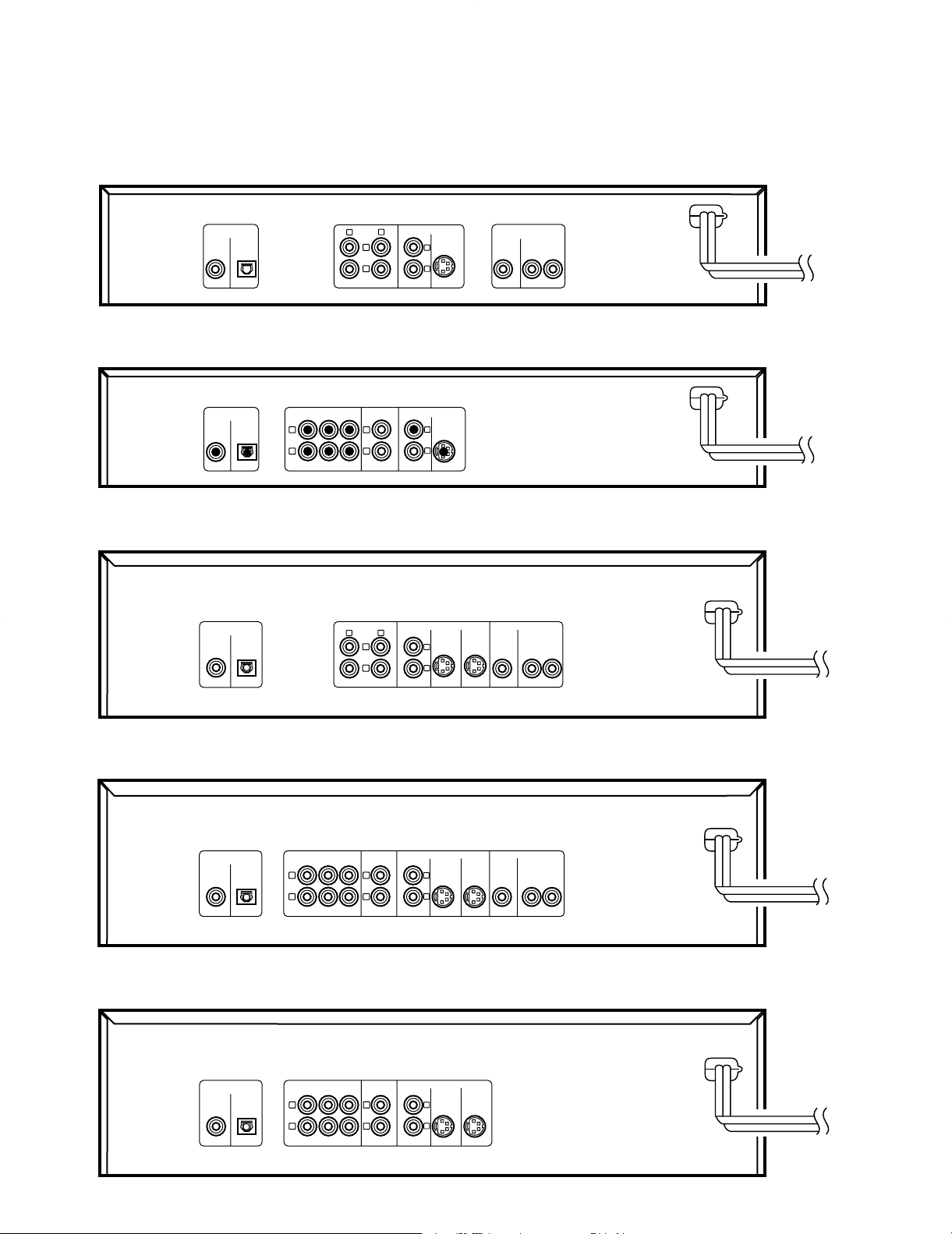
S-VIDEO
VIDEO OUTPUT
COMPONENT
VIDEO OUTPUT
Y
Cb Cr
AUDIO
OUTPUT
L
R
(PCM/BIT STREAM)
COAXIAL OPTICAL
DIGITAL OUTPUT
1
2
1
2
DV-203
CENTER
S-VIDEO
VIDEO OUTPUT
MIX LINE
OUTPUT
6CH. OUTPUT
L
R
L
R
(PCM/BIT STREAM)
COAXIAL OPTICAL
DIGITAL OUTPUT
1
2
FRONT SURROUND SUBWOOFER
DVF-5010/DVF-K7010
S-VIDEO 1
VIDEO OUTPUT
COMPONENT VIDEO OUTPUT
S-VIDEO 2
Y
Cb Cr
AUDIO OUTPUT
L
R
(PCM/BIT STREAM)
COAXIAL OPTICAL
DIGITAL OUTPUT
1
2
1
2
DV-2070
(PCM/BIT STREAM)
COAXIAL OPTICAL
DIGITAL OUTPUT
CENTER
S-VIDEO 1
VIDEO OUTPUT
MIX LINE
OUTPUT
S-VIDEO 2
FRONT SURROUND SUBWOOFER
6CH. OUTPUT
L
R
L
R
1
2
DVF-9010 (E,M,T)
DVF-9010 (Y)
COMPONENT VIDEO OUTPUT
Y
Cb Cr
(PCM/BIT STREAM)
COAXIAL OPTICAL
DIGITAL OUTPUT
CENTER
S-VIDEO 1
VIDEO OUTPUT
MIX LINE
OUTPUT
S-VIDEO 2
FRONT SURROUND SUBWOOFER
6CH. OUTPUT
L
R
L
R
1
2
CONTROLS
REAR PANEL
4
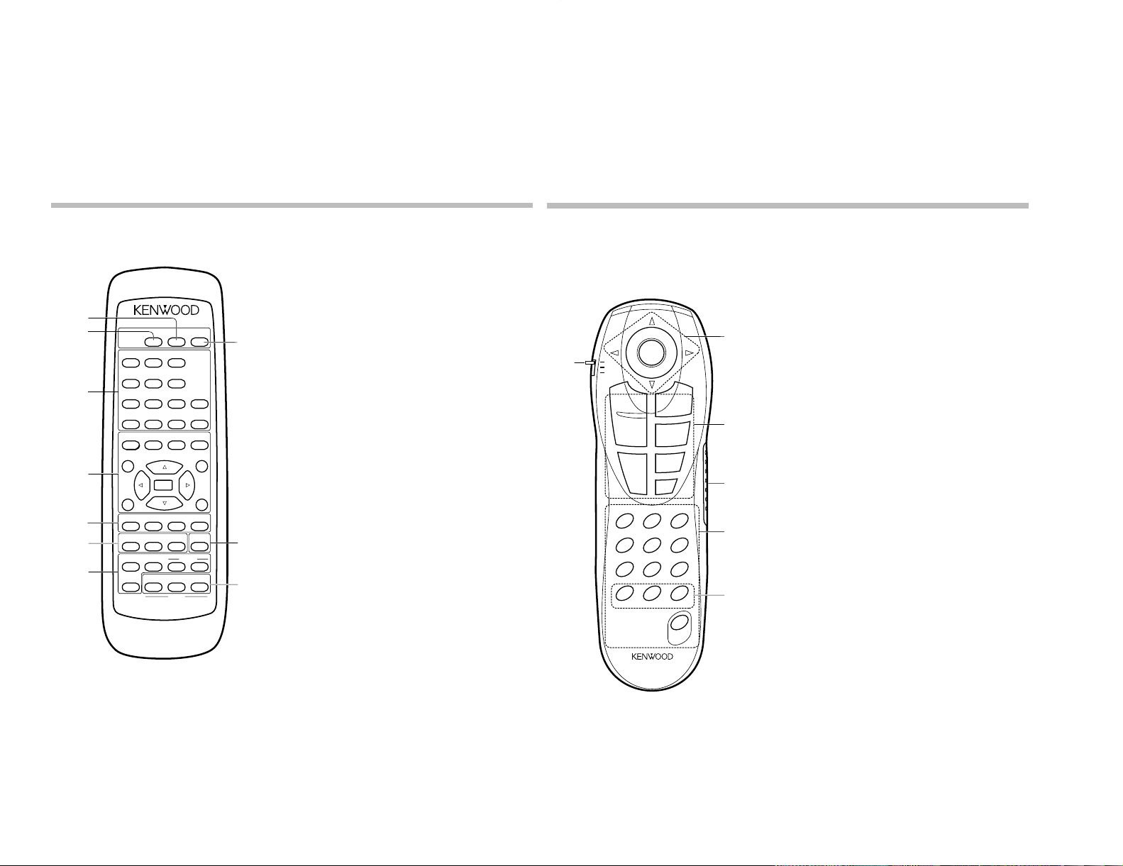
Remote control unit
The remote control unit incorporates the basic operation keys as well as a variety of applied operation keys so that it can be
used in a wide range of purposes.
Use care to store the remote control unit in a safe place so as not to lose it.
* The proper positioning of the mode switch (DVD, CD, DVD SET UP) is variable depending on the control and play modes.
Set the mode switch according to the desired control and play modes.
Information inside ( ) below indicates the mode switch setting position to implement the function in question.
Model: RC-D0705
Infrared ray system
1
Remote control mode switch
DVD
CD
DVD SET UP
2
Joystick/ENTER/Pause/forward search/reverse search
keys
(DVD, CD, DVD SET UP)
Joystick (
%, fi, @, #
) keys
ENTER key
Pause (
8
) key
Forward and reverse search (
1, ¡
) keys
3
CD, VCD and DVD related control keys
SKIP DOWN (
4
) and SKIP UP (¢) keys
(DVD, CD, DVD SET UP)
ON SCREEN key (DVD, CD, DVD SET UP)
PLAY (
3
) key (DVD, CD, DVD SET UP)
STOP (
7
) key (DVD, CD, DVD SET UP)
MENU key (DVD, DVD SET UP)/P.MODE key (CD)
RETURN key (DVD, CD, DVD SET UP)
4
DISPLAY key (DVD, CD, DVD SET UP)
5
TV monitor related control keys
Numeric (0 to 9) keys (CD)
C (Clear) key (DVD, CD, DVD SET UP)
REPEAT key (DVD, CD, DVD SET UP)
A-B REPEAT key (CD)
SET UP key (DVD SET UP)
MEMORY key (DVD)
VIRTUAL SURR. key (DVD)
TITLE key (DVD)
ANGLE key (DVD)
AUDIO key (DVD)
SUB TITLE key (DVD)
OPEN/CLOSE (
0
) key (DVD)
6
CD-TEXT related control keys
TEXT DISP. key (DVD)
ALL INFO. key (DVD)
TITLE SEARCH key (DVD)
VIRTUAL
SURR.
DISPLAY
OPEN
/CLOSE
12
3
4
56
A-B
REPEAT
REPEAT
7
8
9
CLEAR P.MODE
0
TITLE MENU
RETURN
ON
SCREEN
4¢
ANGLE AUDIO SUB TITLE
MEMORY
7
3
1¡
8
ASSIST
VOCAL
KARAOKE
HIT
MASTER
SET UP
KARAOKE
MODE MELODY
UP
DIGITAL
ECHO
DOWN
REQUEST
I
È
Si
KEY
CONTROL
7
2
1
5
6
3
4
5
6
6
ENTER
0
Remote control unit
The remote control unit incorporates the basic operation keys as well as a variety of applied operation keys so that it can be
used in a wide range of purposes.
Use care to store the remote control unit in a safe place so as not to lose it.
Model: RC-D0505
Infrared ray system
1 DISPLAY key
2 VIRTUAL SURR. key
3 CD, VCD and DVD related control keys
Numeric (0 to 9) keys
CLEAR key
P.MODE key
A-B REPEAT key
REPEAT key
4 CD, VCD and DVD related control keys
Skip down (4) and Skip up (¢) keys
Stop (7) key
Play (3) key
Cursor (%, fi, @, #) keys
ENTER key
Pause (8) key
Forward and reverse search (1, ¡) keys
TITLE key
MENU key
RETURN key
ON SCREEN key
5 TV monitor related control keys
ANGLE key
AUDIO key
SUB TITLE key
MEMORY key
SET UP key
6 Karaoke-related control keys
KARAOKE key
HIT MASTER key
ASSIST VOCAL key
KARAOKE MODE key
MELODY key
DIGITAL ECHO (DOWN/UP) keys
REQUEST key
Flat ( ) key
Natural ( ) key)
Sharp ( ) key
7 OPEN/CLOSE (0) key
I
i
È
8
1
ENTER
DVD
1
CD
DVD
SET UP
¢
SKIP UP
4
SKIP DOWN
ON
SCREEN
C
1
4
ANGLE SUB TITLE
7
MENU
P.MODE
RETURN
A-B REPEAT
REPEAT
REPEAT
23
VIRTUAL SURR.MEMORY TITLE
5
AUDIO
89
ALL INFO.TEXT DISP. TITLE SEARCH
0
OPEN
/ CLOSE
SET UP
3
PLAY
7
STOP
6
0
2
¡
CONTROLS
3
DV-203/2070/DVF-5010/9010/K7010
4
DISPLAY
5
6
5
DV-203/2070/DVF-5010/9010/K7010
3
4
2
1
7
8
5
5
6
9
11
12
12
12
12
12
12
10
x2
x2
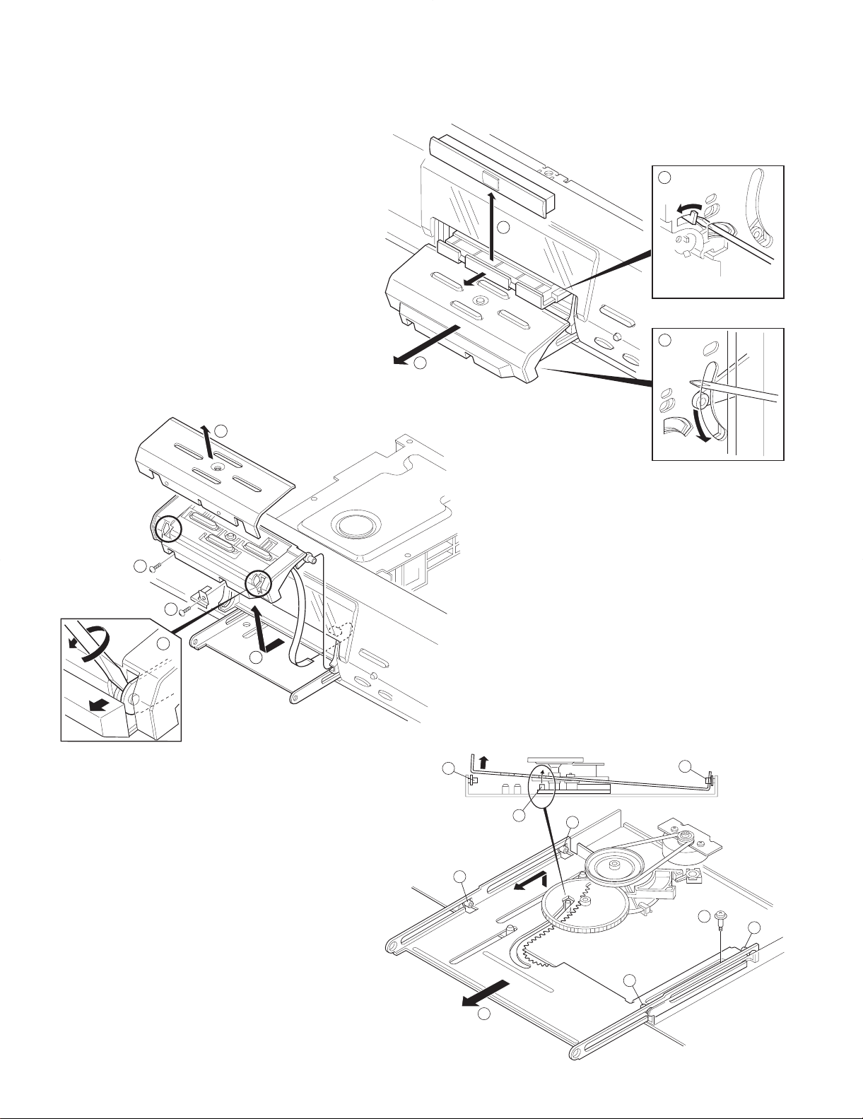
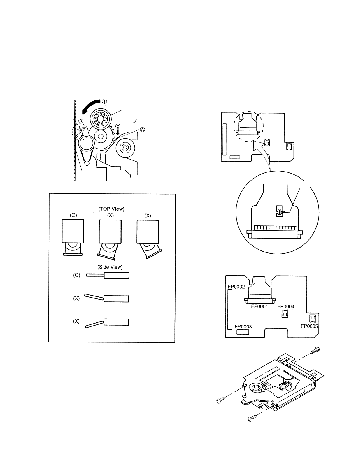
DISASSEMBLY FOR REPAIR (DV-2070, DVF-9010)
1. How to open the door panel and the tray if not comes out.
(1) See the bottom of a set, then move the arm of the
door mechanism by a screw driver (1) and pull out
the door panel (2).
(2) Move the rotary cam of the DVD mechanism by a
screw driver (3), then pull out the tray and remove
the tray panel (4).
3. How to remove the moving door mechanism
1. Remove the 1 screw (9), Then pull the slider (0) till last
2. While raise the slider of left side, remove the slider from the
bosses (-,=)
2. How to remove the door panel.
(1) Remove 2 screws (5), then remove the door
panel (6).
(2) Remove 2 bosses (7), then remove the door
escutcheon (8).
6
DV-203/2070/DVF-5010/9010/K7010
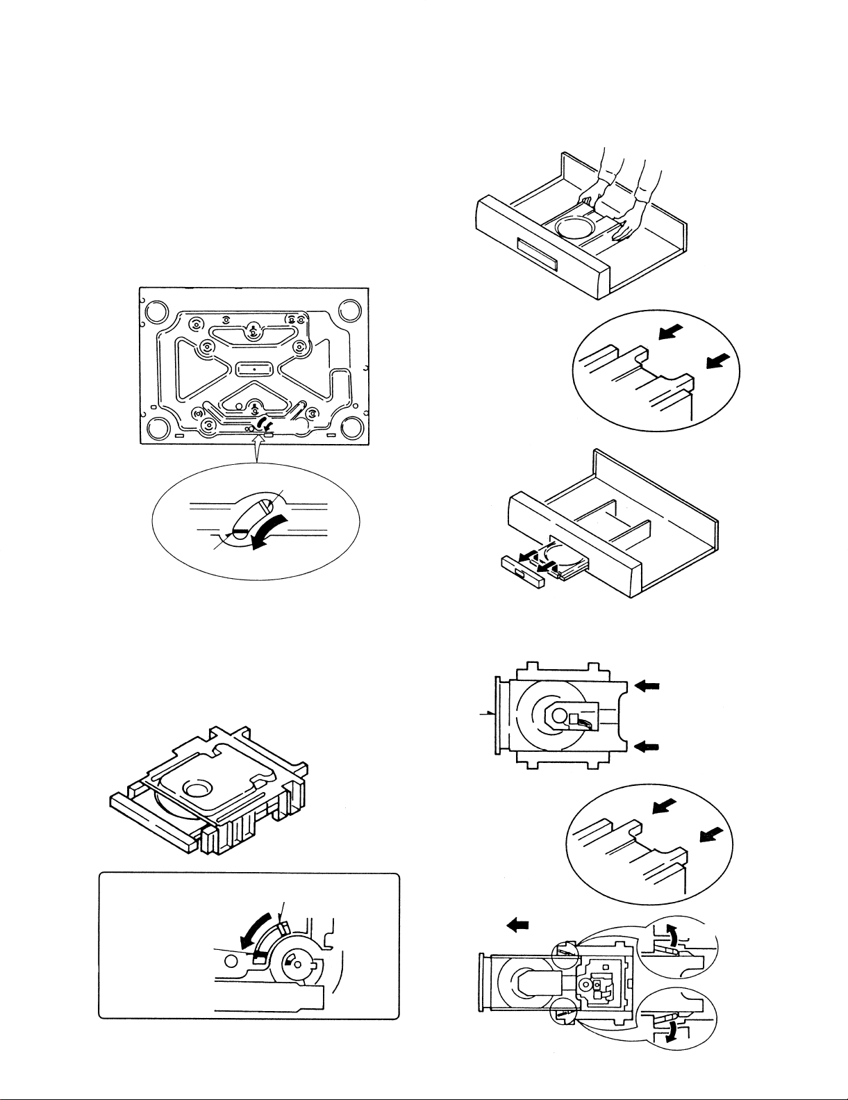
DISASSEMBLY FOR REPAIR
How to Disassemble mechanism.
1. The disc is not coming out by pressing the open botton.
1. Remove the case and DVD disc in the unit.
2. Insert the small screw driver into the hole on
the bottom chassis.
3. Travel the rotary cam to the tray open position.
4. Travel the tray to open position by hand.
5. Remove the dress panel.
OPEN
CLOSE
OPEN
2. The Loading Tray
1. Travel the rotary cam to the tray open position.
2. Travel the tray to open position by hand.
3. Open the hooks of the tray holder and pull out it.
TRAY
CLOSE
PUSH
TRAY
TRAY
OPEN
OPEN
7
DV-203/2070/DVF-5010/9010/K7010
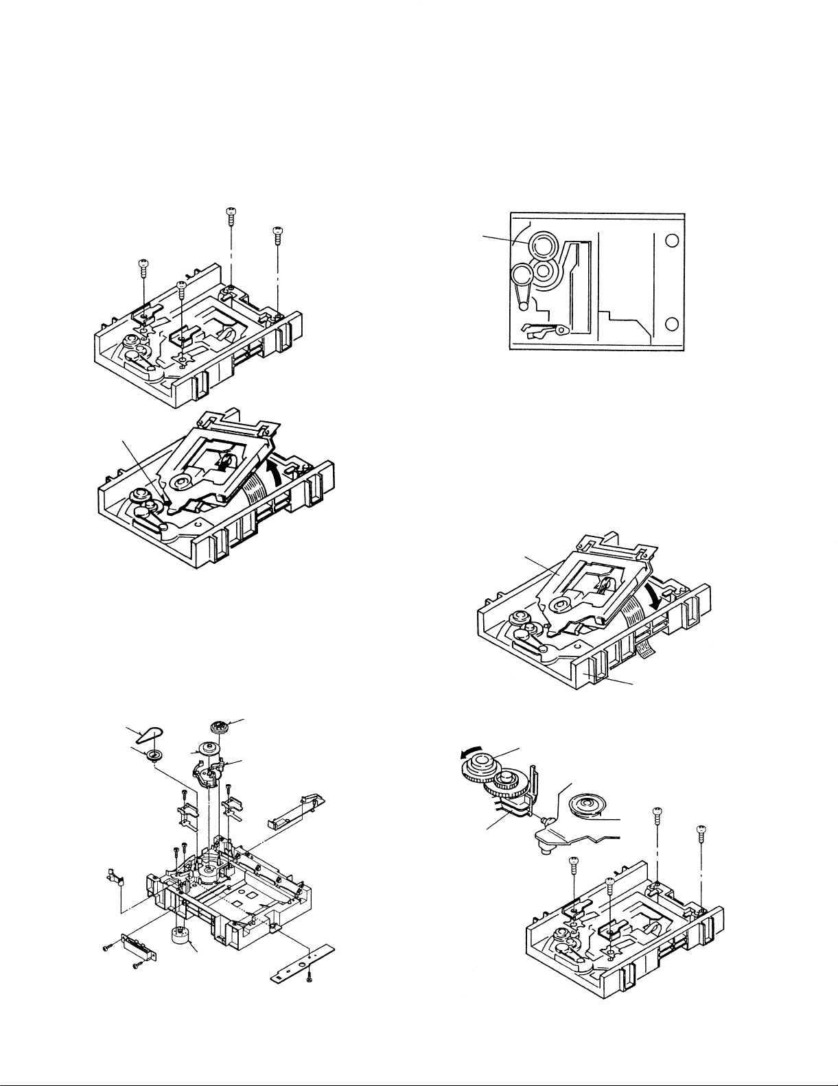
DISASSEMBLY FOR REPAIR
3. Traverse Unit
1. Remove the screws fixing the plate spring, the chassis
stopper and the spring.
2. Lift the back of the traverse unit and remove it.
CONNECTING
POINT
How to Assemble
1. Loading Mechanism
This mechanism has no order for assembling the loading parts.
TRAY GEAR
2. Traverse Unit
1. Pass the flexible cable from the inside of the loading
base to the outside of that.
2. Insert the top of the traverse unit to the groove of the
rotary cam and fix it with screws.
4. Loading Mechanism Parts
1.The loading parts is avalable without disassemble.
Refer to the followings.
BELT
PULLEY
GEAR
GEAR
TRAY
GEAR
ROTARY
CAM
ROTARY CAM
TRAVERSE
UNIT
TRAY GEAR
LOADING BASE
LOADING
MOTOR
8
DV-203/2070/DVF-5010/9010/K7010
DISASSEMBLY FOR REPAIR
3. Loading Tray
1.Turn the tray gear to move the traverse unit at the bottom position counterclockwisely.
2. Push the A of the rotary cam to the arrow direction.
3. Check the hook to be locked.
4. Load the tray to the loading base straightly.
TRAY GEAR
HooK
How to Replace
1. Preparation
1. Short the pickup short lands for protecting the damage of the statics.
2. Remove all of the flexible cables on the connection
pcb.
3. Remove screws to divide the traverse unit
SHORT
4. Clamper
1. Mount the clamper plate before assembling the
loading base to the unit.
9
DV-203/2070/DVF-5010/9010/K7010
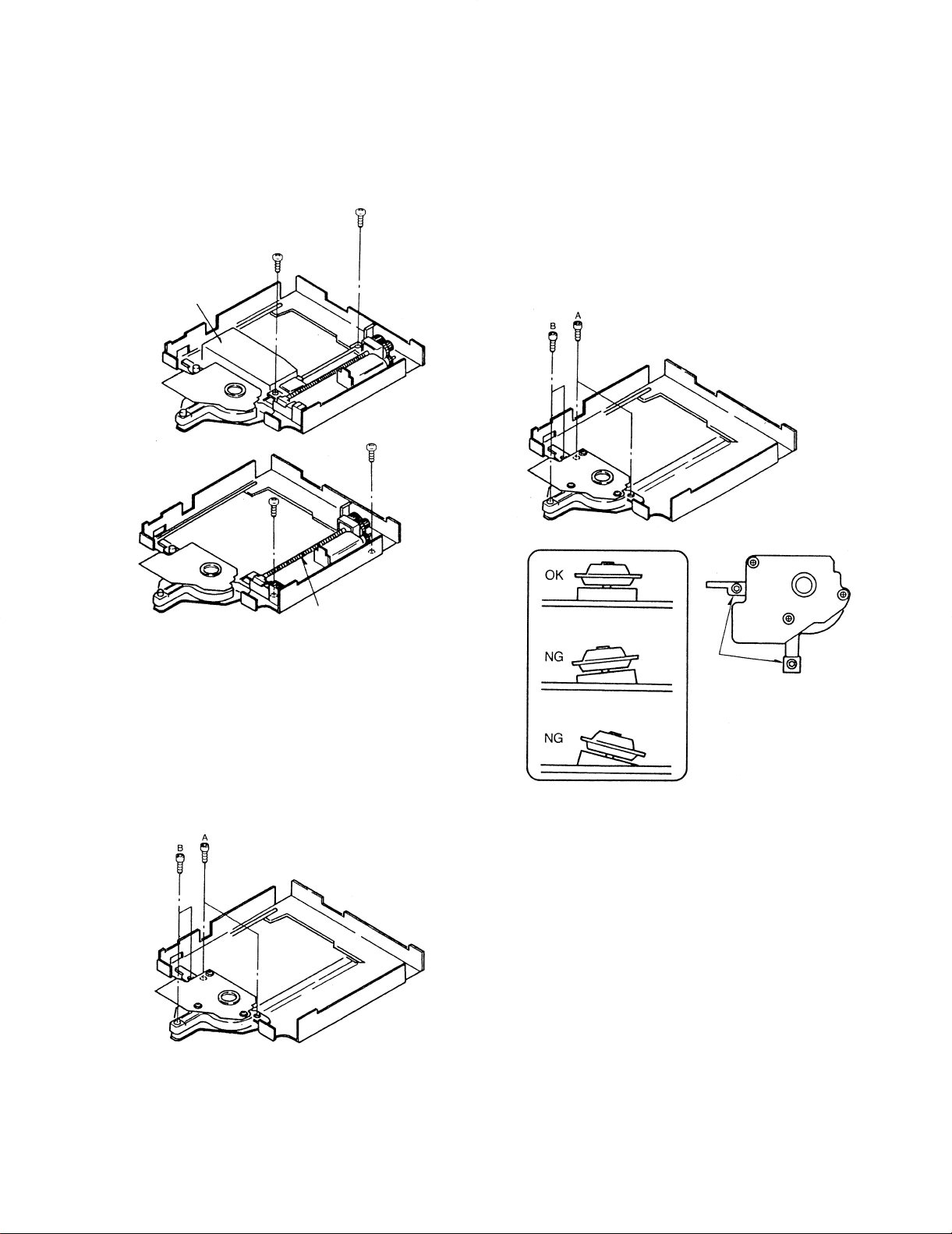
DISASSEMBLY FOR REPAIR
2. Laser Pickup
1.Remove the screws fixing the pickup.
2.Remove the screws fixing the traverse motor.
Pickup
4. Assemble
1. Assemble the traverse unit and the pickup in the
reverse order of disassembly.
2. Fix the A screw and the B adjusting screw when the
disc motor unit mount.
3. Fix the B screw so that the disc motor unit is at a level
with the traverse unit.
TRAVERSE MOTOR
UNIT
3. Disc Motor
1. Remove the A screw and the B screw in the order.
Note: No need to remove the laser pickup when disc
motor replace procedure.
B SCREW
(BLK)
4. After assembled the pickup, the traverse motor unit or
the disc motor, adjust "TANGENTIAL" and "TILT" of
the adjustment.
(Need not adjust this adjustment to exchange the traverse unit.)
10
DV-203/2070/DVF-5010/9010/K7010 DV-203/2070/DVF-5010/9010/K7010
AVR
OP AMP, SOUND SEL.
IC25
DECODER
CD-TEXT
SER.
16BIT
S-RAM
PAR.
IC23
IC26 IC29
u-COM
A
MUTE
MUTE
IC31
J
IC30
Q434
MUTE
Q424,425
DAC
IC3
(1/2)
FILTER
IC18 (1/2)
FILTER
IC18 (2/2)
IC17
IC17
(2/2)
D
P
SWITCH
CONTROL
Q500,502
LED
FL AC
DISPLAY
DRIVER
FL DOT
DISPLAY
FL
IC1 ED1
SENSOR
A1
REMOTE
SWITCH
KEY
R
DETECT
Q105
MIC
MUTE
IC101
IC101
Q103
33dB
IC102
33dB
Q104
MUTE
IC102
Q101
L
IC7 (2/2)
FILTER
IC3
DAC
IC7 (1/2)
FILTER
IC8 (2/2) IC8 (1/2)
D.R.I.V.E
24 BIT
IC2
B
F
Q430,431
CONTROL
LEVEL
Q423
KARAOKE
Q422
Q433
Q432
K
Q407,409
MUTE
IC8,9
SELECT
MUTE
Q406,408
MUTE
Q403,405
MUTE
Q402,404
Q407,409
MUTE
Q402,404
MUTE
Q403,405
MUTE
Q406,408
MUTE
O
IC4
DAC
Q426,427
MUTE
E
IC13 (2/2)
FILTER
IC13 (1/2)
FILTER
IC5
DAC
Q428,429
MUTE
IC11 (1/2)
IC11 (2/2)
FILTER
FILTER
MUTE
CONTROL
Q437,439 Q438,440
IC33 (1/2) IC33 (2/2)
MUTE
CONTROL
IC15,16
ADD
IC6
E. VOL
E. VOL
IC7
11.4dB
IC14 (2/2)
IC14 (1/2)
Q411,413
Q410,412
MUTE
MUTE
Q415,417
Q414,416
MUTE
MUTE
IC12 (2/2)
IC12 (1/2)
11.4dB
11.4dB
11.4dB
Q239
FILTER
Q219-221
Q217,218
6dB 75 DRIVER
Q222,223
75 DRIVER
Q240
FILTER
Q227,228
6dB
Q224-226
Q210-213
Q204-208
Q203
Q209,237
FILTER
FILTER
Q236
NR +
6dB
Q200-202
6dB
75 DRIVER
75 DRIVER
75 DRIVER
75 DRIVER
IC2
DRIVER
IC24
MOVING PANELMOVING PANEL
MOTOR
IC2 (1/2)
IC2 (2/2)
H
Q600,601
IC32
COAX OUT
OPT OUT
1 L
2 R
OUTPUT
ANALOG
2V/510
1 L
2 R
G
1 Lch
2 Rch
3 SL
4 SR
6 SW
5 CT
E
Cb
Y
Cr
C
Y/C OUT1
Y/C OUT2
I
OUTPUT
1Vp-p/75
COMPONENT
2 COMP OUT2
1 COMP OUT1
Cr 75
Cb 324mVp-p/
Y
1Vp-p/75
OUTPUT
COMPONENT
286mVp-p/
1Vp-p/75
C
75
OUTPUT
Y
S-VIDEO
DAC
240V
Q
MIC1
KEY
CONTROL
J103
J101
J102
MIC2
IC5
DAC
C
N
M
VR1
-21
COAX 0.5Vp-p/75
OPTICAL
DIGITAL OUTPUT
-15dBm
NO
YES
GENERAL MARKET
EUROPE
U.K.
PX
E9
T9
M9
Y9
A, B
DESTINATION
COUNTRY
DVF-9010
ABB.
GENERAL MARKET M0
U.S.A. K9
NO
YES
C
YES
D, E,
NO
G
YES
H, I,NOJ, K, L,
YES
NO
N
NO
YES
1, 2
3, 6,
NO NO
4, 7
YES
5, 8
20-22
22-71
20-11
20-21
(X14-48X-XX)
DISPLAY UNIT
(W02-266X-XX)
2-05
0-05
1-05
DVD CIRCUIT
E, O,
YES
DVF-5010
DESTINATION
COUNTRY
GENERAL MARKET
EUROPE
GENERAL MARKET M6
U.K.
E5
T5
M5
NO
ABB.
A, B, C, D, F, G, H,
(W02-266X-XX)(X14-48X-XX)
NO YES
30-22
32-71
30-21
2-05
1-05
1-8,
9, 10
DISPLAY UNIT DVD CIRCUIT
DESTINATION
COUNTRY
DVF-K7010
CHINA
GENERAL MARKETC7M7
NO
ABB.
A, B, C, D, F, G,
YES
E, J, K,
(W02-266X-XX)
NO YES
1-8,
9, 10
(X14-48X-XX)
33-01
30-20
1-05
DISPLAY UNIT DVD CIRCUIT
DESTINATION
COUNTRY ABB.
NO
A, B, E, F, J,
(W02-266X-XX)
YES
C, D, G, H,
YES
3, 6
1, 2, 4, 5,
NO
(X14-48X-XX)
DISPLAY UNIT
20-11
DVD CIRCUIT
0-05
DV-2070
DV-203
U.S.A.
DESTINATION
COUNTRYK5ABB.
YES
(W02-266X-XX)
1-10
NO
(X14-48X-XX)
DISPLAY UNIT
YES
11, 12
30-11
DVD CIRCUIT
0-05
A, B, C, D, E, F, H,
I, M, J, K, L, N
G, O,
P, Q
NO
7-12
K, L, N, O, P I, M, Q
H, I, M, N, Q L, O, P 11, 12
I, M, J, K, L, N P, Q
11, 12
F
O, PM, Q
9-12
AC120-
2V/510
6ch
OUTPUT
D3.3V/A+5V/D+5V/M+9V/
A+12V/A-12V/FL-35V
+12V
-12V
SLKCK/CLDCK
DACMUTE/IW0/
EMPH/IW1
SCLK
SRDT
u-COM+5V
D+3.3V/A+5V
M+9V/D+5V/
384fs
POWER
STB/CLK/DATA
MICMUT
ECHOMUT
MIC
ECHO
IEC958
ML/MC/MD
MICMUT
DOUT0
786fs
DACMUTE
BCK/LRCK
MCK
DATA0
DOUT1
DOUT2
Lch
Rch
ZERO0
DACMUTE
MIC CONT2
MIC CONT1
VOICE EDIT
BCK
LRCK
DATA
RO-
RO+
LO-
LO+
DATA LO+
LRCK
BCK
LORO+
RO-
DATA
MCK
BCK/LRCK
SFI/BITO/BITI
SFI/BITO/BITI
PMUTE
CD-2CH
ECHO
MIC
Lch
Lch
Rch
Rch
MIXL
MIXR
4
3
2
1
8
7
6
5
MIXR
MIXL
Rch
Lch
Rch
Lch
MIX LO
MIX RO
RO
LO
CD-2CH
Lch
MIXR
12
11
10
Rch
MIXL
9
BCK/LRCK
ML/MC/MD
MCK
DATA1
DACMUTE
ZERO1
SR
SL
SR
SL
ML/MC/MD
BCK/LRCK
MCK
DATA2
DACMUTE
ZERO2
SW
CT
SW
CT
AMUTE
STB
DATA/CK
STB
STB
DATA/CK
SR
SL
SW
CT
NR1/NR2/NR3
DASDATA
DASMC/
DASML/
MDRIVEO/MDRIVRI
CB/B
CR/R
NR1/
NR2/
NR3
Y
C
MO-
MO+/
ACC. -DRIVE/LD-CONT.
RF/FE/TE/SENS. SW
MIXR
MIXL
SR
CT
SW
SL
SW
CT
SR
SL
Cr
Y
Cb
Y/C1
Y/C2
COMP
Cr
Y
Cb
COMP
Y/C2
Y/C1
Cr
Cb
Y
Y/C2
Y/C1
COMP
+5V
FLAC
SBCK/SUBC/
DQSY/
BCK/LRCK
24bit L
24bit R
MICMUTE
FL-35V/D+5V
MUTE
CONT.
ELECTRIC UNIT
(X25-616X-XX)
(W02-2658-X5)
POWER SUPPLY
SWITCHING
(X14-48XX-XX)
DISPLAY UNIT
(X14-483X-XX) (B/2)
KARAOKE
(X32-3670-00)
PROCESSOR UNIT
D.R.I.V.E
DVD CIRCUIT
DVD MECHA.
(D40-1580-05)
PHONES
(X14-482X-XX) (C/4)
DVF-K7010/
DV-2070/DV-203/
DVF-9010/DVF-5010/
DVD CIRCUIT MAKER PARTS No.
W02-2660-05 VEP96533A
W02-2661-05 VEP96533B
W02-2662-05 VEP96533C
MIX OUT
(AUDIO OUT 2)
AUDIO
OUT 1
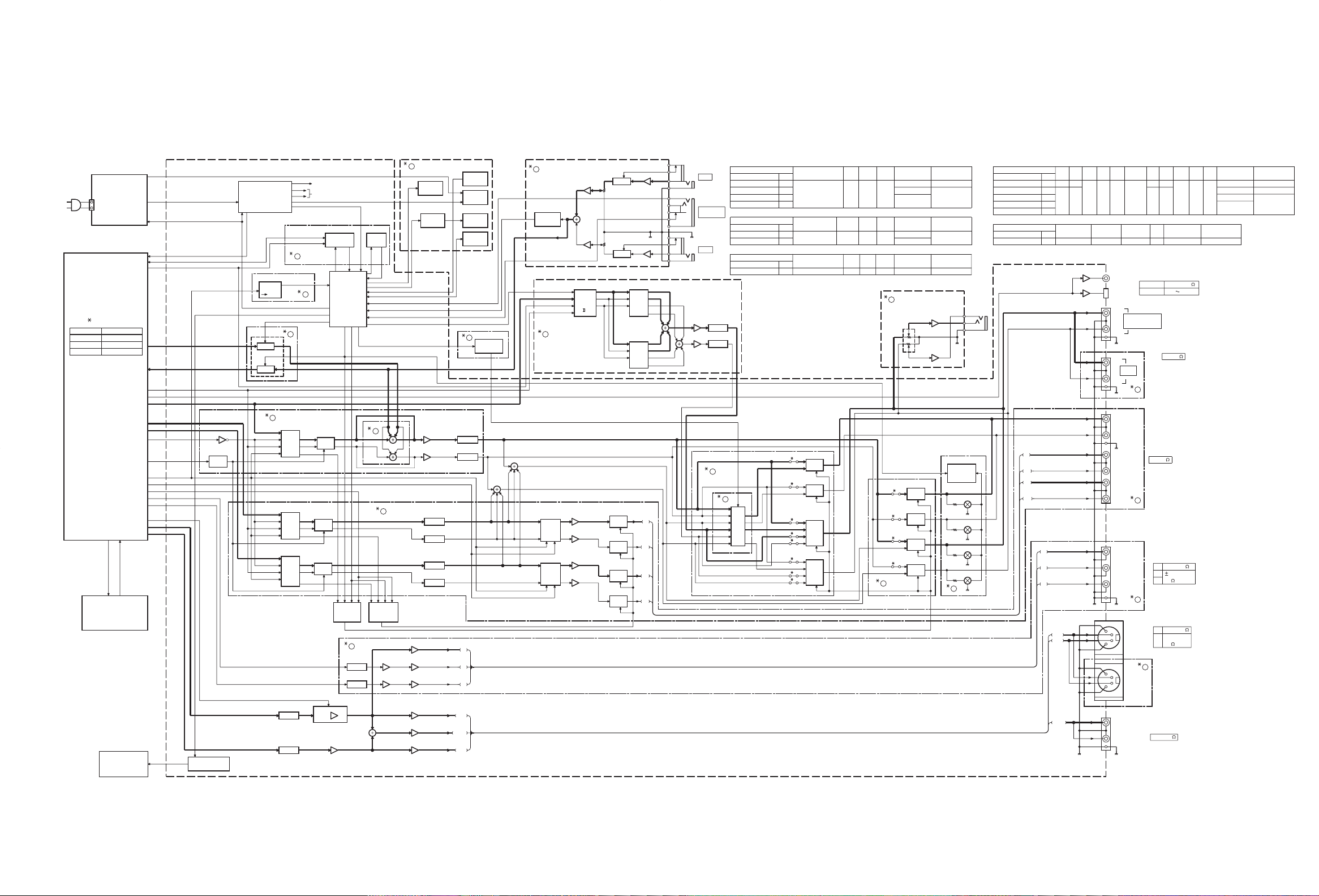
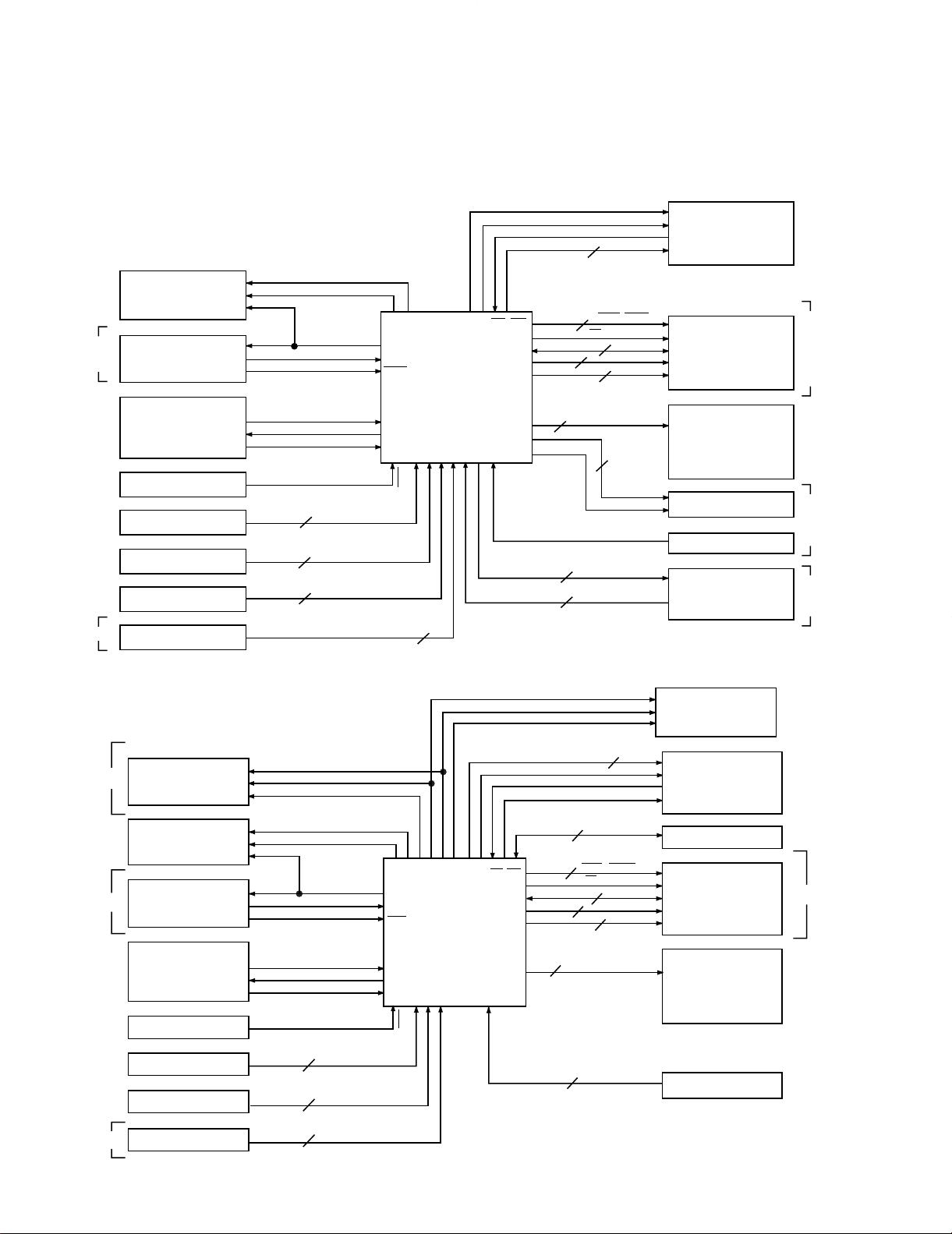
BLOCK DIAGRAM
11
12
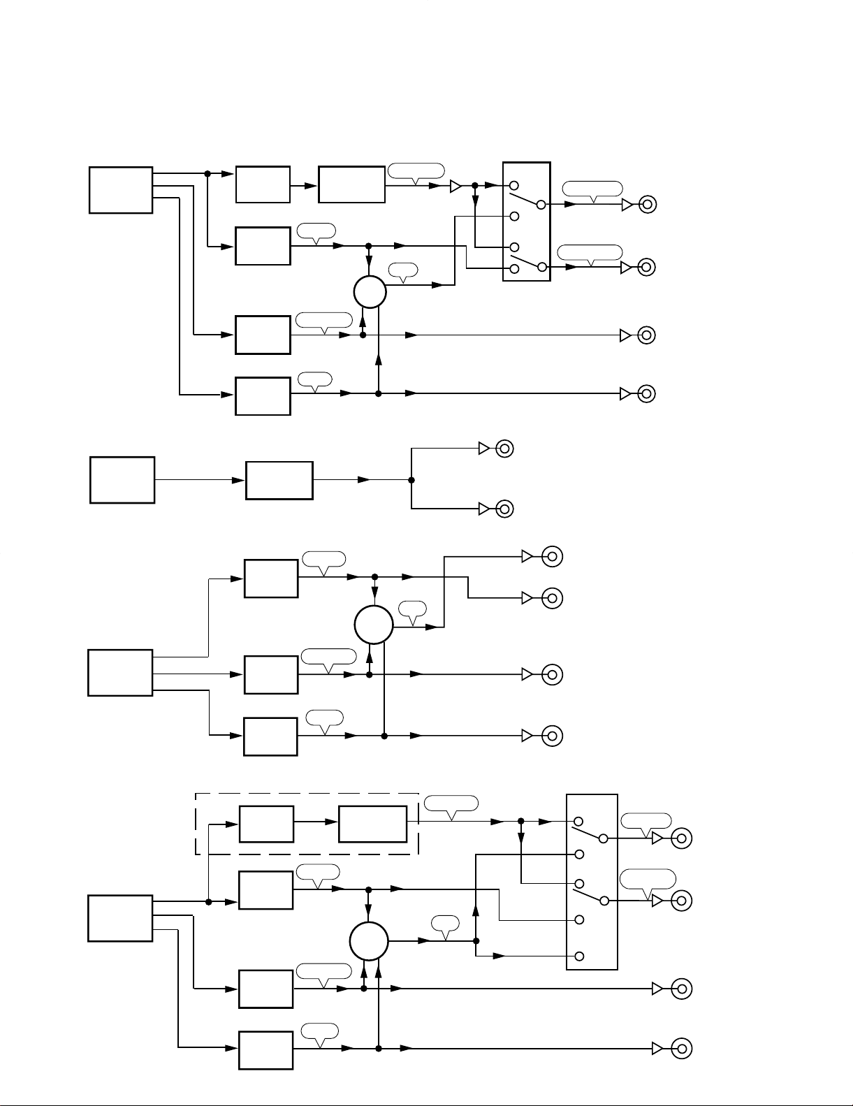
CIRCUIT DESCRIPTION
DRIVE¿
(X32) IC2
DVD
MAIN
PCB (W02)
DVD
MAIN
PCB (W02)
DOUT0
FRONT
SURROUND
DRIVE OUT
MIX or DRIVE
FRONT or DRIVE
C, SW
MIX
DOUT1
DOUT2
DOUT0
+
DAC
(X25) IC3
DAC
(X25) IC4
DAC
(X25) IC3~5
DAC
(X25) IC5
DAC
(X32) IC3, 5
(X25) IC8, 9
MIX OUT
FRONT OUT
SURROUND OUT
AUDIO OUT 1
AUDIO OUT 2
C, SW OUT
DVD
MAIN
PCB (W02)
DVD
MAIN
PCB (W02)
DAC
(X25) IC3
DAC
(X25) IC3
DAC
(X25) IC4
DAC
(X25) IC5
DRIVE¿
(X32) IC2
DAC
(X32) IC3, 5
MIX OUT
FRONT OUT
+
+
SURROUND OUT
C, SW OUT
MIX OUT
FRONT OUT
SURROUND OUT
C, SW OUT
(X25) IC8, 9
DAC
(X25) IC4
DOUT0
FRONT
FRONT
DRIVE OUT
C, SW
C, SW
MIX
MIX
SURROUND
MIX or DRIVE
FRONT or MIX
or DRIVE
SURROUND
DOUT1
DOUT2
DOUT0
DOUT1
DOUT2
DAC
(X25) IC5
1. Audio circuit for model and destination
DVF-9010 E1T1M1M2 type
DV-203/2070/DVF-5010/9010/K7010
DV-2070, DV-203, DV-S701 K type
DVF-9010 Y type, DVF-5010 M type, DVF-K7010 M type
DV-S701 E1T1M2 type, DV-K751
13
DV-203/2070/DVF-5010/9010/K7010
(X14) IC1
FL (VFD) dot driver
CE
DI
CL
SCLK
SRDT
DQSY
DSPSCLK
SCK0
SCK1
HD6433396A65F
Main u-com
D0~D7
RD, WR
A0~A15
RxD1
IRQ1
TxD0
RxD0
CMD
STATUS
IRQ0
TxD1
AN2, 3, 4
VERSION
3
1
2
8
A1, A0, SF1, SF0,
IW1, IW0, DEM, MUT
POWER-MUTE
CE
bit0, 1 fs1
READ/WRITE
AS
DATA
Address
BANK
IFS, IFD
IFL
motor drive2
2
8
4
1
2
3
11
2 lid switch
2channel
CD TEXT
EXCEPT
DVF-K7010
DVD mecha u-com
LC75712N
LC 89170M
MN102L25D
Remote sensor
Operation key
Model distinction
DVF-K7010
DAC
MIC remote control
(X25) IC26
DVD PCB (IC6201)
(X14) A1
(X25) IC3~5
(X14) J103
Other circuit
SRAM
LED
DVD mark
96k sampling
DTS. MPEG
Virtual surround
KARAOKE DSP
MIC jack detect
Moving panel
TC9409BF
D40-1600-02
DV-2070
DVF-9010
DVF-K7010
EXCEPT
DVF-K7010
N345256SOA-55
(X25) IC29
(X25) IC25
(X14)
(DVD PCB) IC4631
(DVD PCB) IC4631
KARAOKE DSP
IFS
IFD
IFL
CE
DI
CL
SCLK
SRDT
DQSY
TC9409BF
LC75712N
LC89170M
DSPSCLK
CMD
STATUS
MN102L25D
Remote sensor
Operation key
Model distinction
DAC
DVD PCB (IC6201)
DVD Mecha u-com
2
1
8
A1, A0, DEM, MUT
(X14) A1
(X25) IC3~5
(X14) IC1
FL(VFD) dot driver
CD TEXT
(X25) IC26
(X25) IC25
SCK0
SCK1
HD6433396A65F
Main u-com
D0~D7
RD, WR
A0~A15
RxD1
IRQ1
TxD0
RxD0
IRQ0
TxD1
AN2, 3, 4
VERSION
POWER-MUTE POWER
CE
MUTE, EMPH
BUSY, DATA
STB
CK
DATA
READ/WRITE
AS
DATA
Address
BANK
2
8
2
1
2
2
2
11
2ch downmix
DV-S701
DV-S701
DV-K751
Other circuit
MIC VOL.
SRAM
LED
DVD mark
STANDBY
Shuttle encoder
DV-S701
N345256SOA-55
System control
TC9412F
(X25) IC29
(X14) IC102
(X14)
CIRCUIT DESCRIPTION
2. Main microprocessor : HD6433396A65F (X25: IC25)
2-1 Block diagram
DV-2070, DVF-5010, DVF-9010, DVF-K7010
DV-K751/S701
14

DV-203/2070/DVF-5010/9010/K7010
CIRCUIT DESCRIPTION
2-2 Pin description
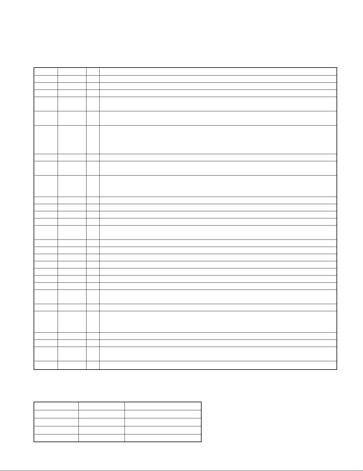
Pin No. Pin Name I/O Description
1 /RES I Input port of the microprocessor reset
2,3 X/ETAL I/O Port of ceramic oscillator
4,5 MD1/0 I Operation mode0(fixed H) and 1(fixed L)
6 /NMI – No use
7 /STBY – No use
8 VCC – Power supply(+5V)
9 DSPCLK I Input port of the clock signal from the mechanism microprocessor
10 STATUS I Input port from the mechanism microprocessor reset
11 CMD O Output port to the mechanism microprocessor reset
12 VSS – GND
13,14 – – No use
15 /AS O Access mode of extra-address
16 /WR O Read mode of extra-address
17 /RD O Write mode of extra-address
18 REMOCON O Input port of remote control signal
19 DQSY I Input port of read signal from CD-TEXT IC
20
21
22 SDATA I/O Synchro data signal
23 IFS O Karaoke DSP serial clock output
24 IFD O Karaoke DSP serial data output
25
26
27 POWER O Power supply control port H : standby, L : power on
28
29 AVCC – Standard voltage for A/D
30
31
32,33 KEY0,1 I Key input port 0,1
34 KEY2 I Key input port 2
35 VERSION I Model selector
36,37 – – No use
38 AVSS – GND for A/D
39 LED 96kHz O 96kHz sampling indicator H : on, L : off
40
41 LED DVD O DVD indicator H : on, L : off
42
43 BB-A1 I DAC data register address A1
44
45
46
47 VCC – Power supply
48
/2 CHANNEL O 2 channel H : except 2CH, L : 2CH
/CD O CD H : except CD, L : CD
BIT 0 O Bit 0 H : 16 or 20bit, L : 24bits
SYNCHRO BUSY I/O Synchro busy signal
PANEL OPEN O Moving panel motor driver 0
CK O KARAOKE DSP/MIC volume IC clock output
PANEL CLOSE O Moving panel motor driver 1
DATA O KARAOKE DSP/MIC volume IC data output
MUTE O DAC mute H : on, L : off
IFL O Karaoke DSP serial latch output
FS1 O Sampling frequency(FS)1 H : 44.1 or 48kHz, L : 96kHz
MIC-MUTE O Mic mute H : off, L : on
BIT 1 O Bit 1 H : 16bit, L : 20 or 24bits
ECHO-MUTE O Echo mute H : off, L : on
PANEL CLOSE SW I Moving panel close switch L : on
MIC REMOTE 1 I Mic remote control 1
PANEL OPEN SW I Moving panel open switch L : on
MIC REMOTE 0 I Mic remote control 0
LED DTS/MPEG O DTS/MPEG indicator H : on, L : off
2CH DOWN MIX O 2 channel down mix H : on, L : off
LED VIRTUAL SURR O Virtual Surround indicator H : on, L : off
LED STANDBY O LED standby H : on, L : off
BB-A0 I DAC data register address A0
STB O Mic volume IC latch output
BB-IW1 I DAC data bit IW1
SHUTTLE SW1 I Shuttle switch 1
BB-IW0 I DAC data bit IW0
SHUTTLE SW0 I Shuttle switch 0
BB-SF1 I DAC sampling rate(SF1)
VOICE-DET I Voice defect H : voice, L : non-voice
15
DV-203/2070/DVF-5010/9010/K7010
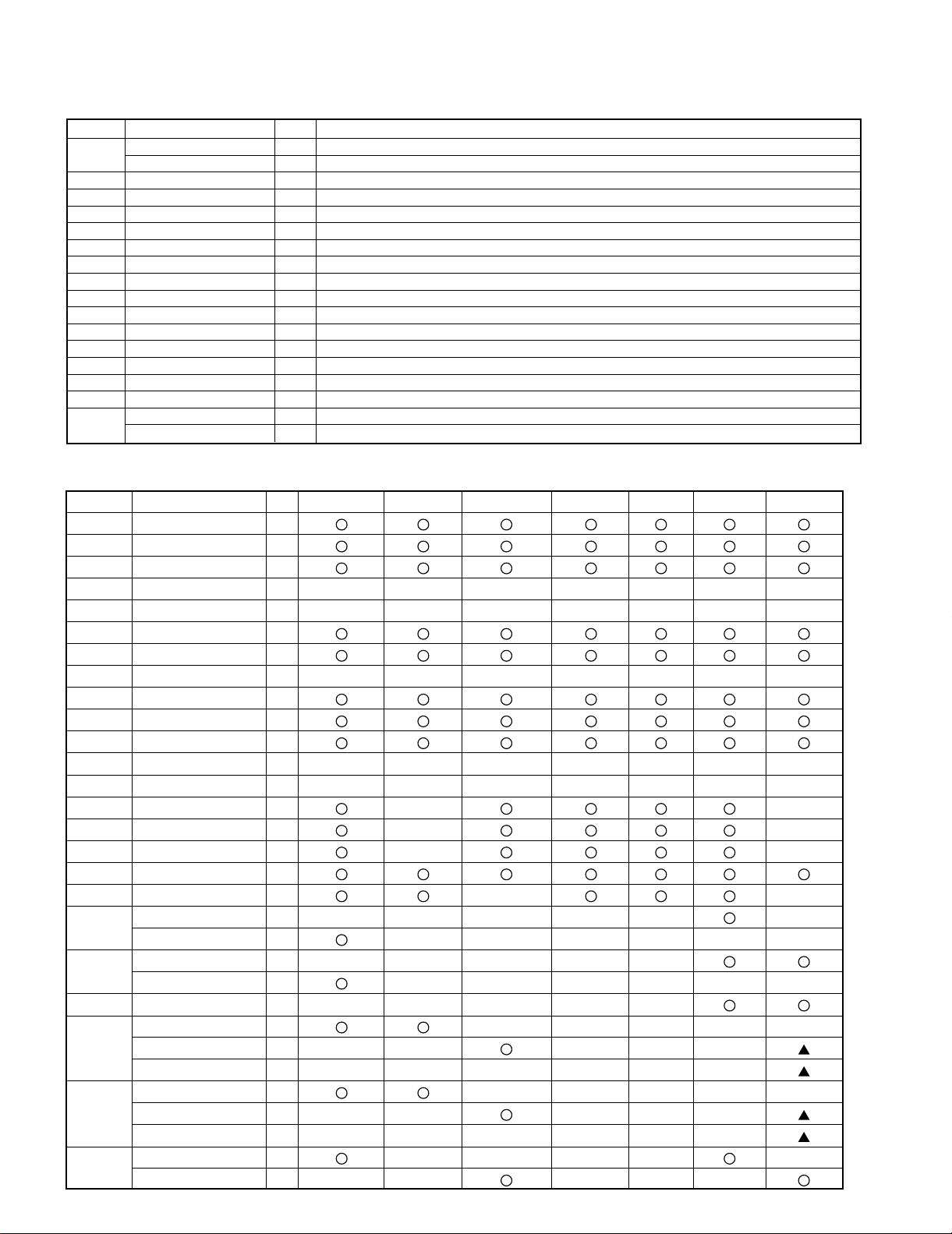
Pin No. Pin Name I/O DVF-9010 DV-2070 DVF-K7010 DV-5010 DV-203 DV-S701 DV-K751
1
/RES
2
XTAL
3
EXTAL
4
MD1
HIGH HIGH HIGH HIGH HIGH HIGH HIGH
5
MD0
LOW LOW LOW LOW LOW LOW LOW
6
/NM1
7
/STBY
8
VCC
9
DSPCLK
I
I
I
I
I/O
I/O
–
–
–
–
–
10
STATUS
I
11
CMD
O
O
O
O
12
VSS
13,14
-
15
/AS
16
/WR
17
/RD
18
REMOCON
I
19
DQSY
I
20
CD
O
2CHANNEL
O
21
SYNCHRO BUSY
I/O
BIT 0
O
22
SYNCHRO DATA
I/O
23
PANEL OPEN
O
IFS
O
CK
O
24
PANEL CLOSE
O
IFD
O
DATA
O
25
MUTE
O
IFL
O
CIRCUIT DESCRIPTION
Pin No. Pin Name I/O Description
49
50 BB-SF0 I DAC sampling rate(SF0)
51 BB-DEM I DAC data deemphasis
52 CE I Chip enable H : Power supply on L : off
53-55 A10-8 O Access address of SRAM
56 VSS – GND
57-64 A7-0 O Access address of SRAM
65-72 D0-7 I/O Access data of SRAM
73 VSS – GND
74 BANK A O Bank selector A
75 P-MUTE O Power mute H : off, L : on
76 EMPH O Deemphasis H : on, L : off
77 CE O FL driver IC serial control latch
78 DI O FL driver IC serial data
79 SRDT I Data for CD-TEXT
80
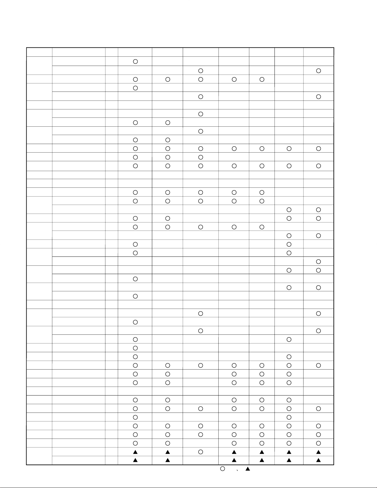
2-3 Port table
BB-MUT I DAC soft mute
MIC-IN I Mic input control port H : in, L : out
CL O FL driver IC serial clock
SCLK O Serial clock for CD-TEXT/VFD
16
DV-203/2070/DVF-5010/9010/K7010
36,37
-
26
FS1
O
MIC-MUTE
O
27
POWER
O
28
BIT 1
O
ECHO-MUTE
O
29
AVCC
30
MIC REMOTE 1
I
PANEL CLOSE SW
I
31
MIC REMOTE 0
I
PANEL OPEN SW
I
32.33
KEY0,1
I
34
KEY 2
I
35
VERSION
I
38
AVSS
39
LED 96KHZ
O
40
LED DTS/MPEG
O
2CH DOWN MIX
O
41
LED DVD
O
42
LED VIRTUAL SURR
O
LED STANDBY
O
43
BB-A1
I
44
BB-A0
I
STB
O
45
SHUTTLE SW 1
I
BB-IW1
I
46
SHUTTLE SW 0
I
BB-IW0
I
47
VCC
48
VOICE-DET
I
BB-SF1
I
49
MIC-IN
I
BB-MUT
I
50
BB-SF0
I
51
BB-DEM
I
52
CE
I
53-64
ADDRESS 0-10
O
65-72
DATA 0-7
I/O
–
–
–
–
–
73
VSS
74
BANK A
O
75
POWER MUTE
O
76
EMPH
O
77
CE
O
78
DI
O
79
SRDT
I
80
CL
O
SCLK
O
=use =common use
Pin No. Pin Name I/O DVF-9010 DV-2070 DVF-K7010 DV-5010 DV-203 DV-S701 DV-K751
CIRCUIT DESCRIPTION
17
DV-203/2070/DVF-5010/9010/K7010
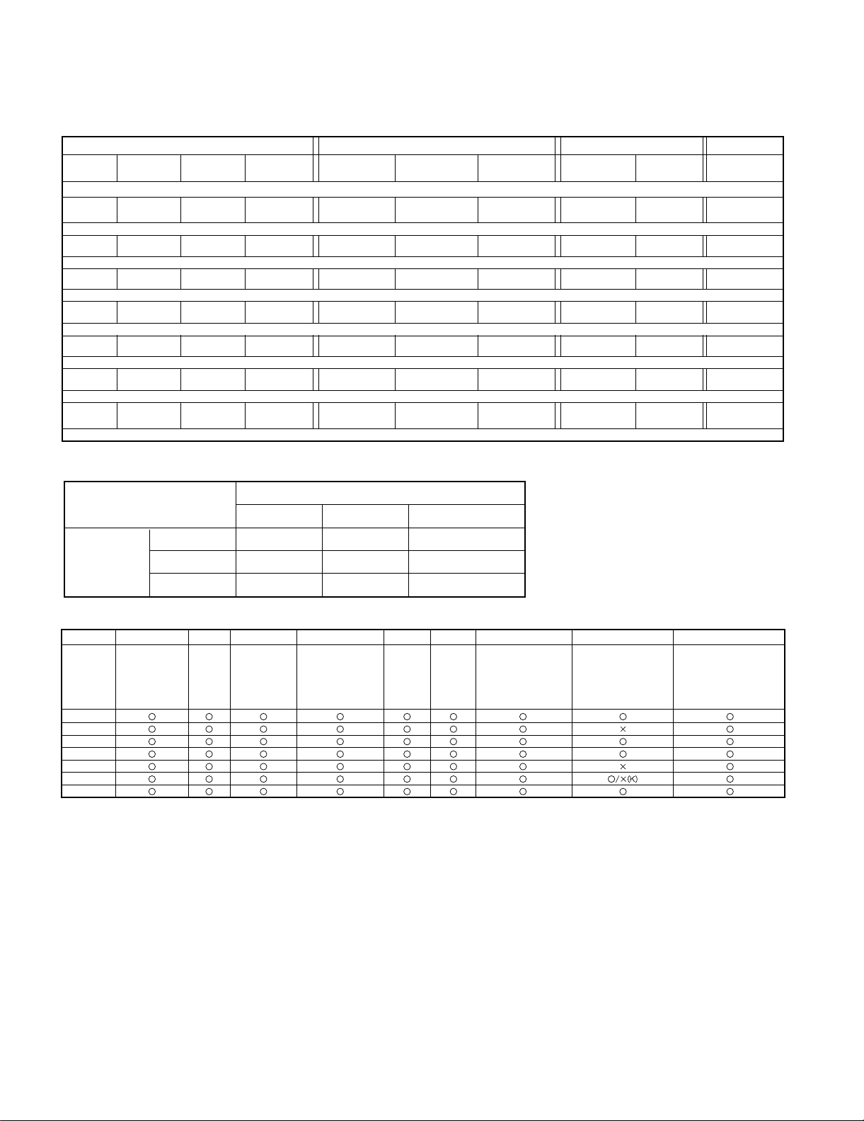
PORT#32 PORT#33 PORT#34 PORT#35
VOLTAGE
DVF-9010/
VD-2070
DVF-K7010
DVF-5010/
VD-203
DVF-9010/
VD-2070
DVF-K7010
DVF-5010/
VD-203
DVF-9010/
VD-2070
DVF-K7010 MODEL NAME
5V
–– – – – – – –
DV-K751
4.58V
2 (LEFT)
––
– REPEAT REPEAT
––
DVF-9010
3.75V
5 (UP)
––
RETURN
8
(STILL/PAUSE)8(STILL/PAUSE)
––
DV-2070
2.92V
ENTER
––
MENU
4
(BWD SKIP)
4
(BWD SKIP)
¢
(FWD SKIP)
KARAOKE DVF-K7010
2.08V
∞ (DOWN)
OPEN/CLOSE OPEN/CLOSE
8(STILL/PAUSE)
¢
(FWD SKIP)
¢
(FWD SKIP)
4
(BWD SKIP)I(FLAT)
DVF5010
1.25V
3 (RIGHT) 3 (PLAY) 3
(PLAY)
PANEL UP/DOWN
1 (FB) 1 (FB)
7
(STOP)
È
(NATURAL;)
DV-203
0.42V
ON SCREEN 7(STOP) 7
(STOP) OPEN/CLOSE ¡ (FF) ¡ (FF)
3
(PLAY)
i
(SHARP) DV-S701
0V
MIC CONTROL
PORT#31
5V 4V 0V
5V
OFF – #
PORT#30
4V
– OFF –
0V
I – LESSON RETURN
items Disc language Ratings Menu language On- screen message FL display TV aspect Digital audio output Speaker setting Other setting
Contents
Audio: Original
Subtitle :Automat
ic Menue: English
8(No limit) English On Bright 4:3
LPCM(DVD): Off
Dolby digital:
Bitstream
MPEG: PCM/DTS:
On
Front: On(small)
Center: On(small)
Rear:On(small)
Subwoofer: On
Delay time: 0ms
Channel balance: 0dB
Still mode: Automatic
Audio during search: On
TV mode(4:3): Pan&scan
D.range compression: On
DVF-9010
DV-2070
DVF-K7010
DVF-5010
DV-203
DV-S701
DV-K751
CIRCUIT DESCRIPTION
3. Voltage matrix
4. MIC PORT
5. Setup and initial items
18
DV-203/2070/DVF-5010/9010/K7010
CIRCUIT DESCRIPTION
6. DAC : AD1855 (X32: IC3, 4)
6-1 Pin description
Pin No. Pin Name I/O Descriptions
1 DGND I Digital GND.
2 MCLK I Master clock input. Connect to an external clock source at either 256,384 or 512Fs.
3 CLATCH I Latch input for control data. This input is rising edge sensitive.
4 CCLK I
5 CDATA I
6 384/256 I
7 X2MCLK I Select internal clock doubler(LO) or internal clock =MCLK(HI).
8 ZEROR O
9 DEEMP I a 50/15 ms response characteristic on the output audio spectrum at an assumed 44.1kHz
10 48/96 I Selects 48kHz(LO) or 96kHz sampling frequency control.
11 AGND I Analog GND
12 OUTR+ O Right channel positive line level analog output
13 OUTR- O Right channel negative line level analog output
14 FILTER O
15 AGND I Analog GND
16 OUTL- O Left channel negative line level analog output
17 OUTL+ O Left channel positive line level analog output
18 AVDD I Analog power supply. Connect to the analog +5V supply.
19 FILTB - Filter capacitor connection, connect 10uF capacitor to AGND.
20 IDPM1 I Input serial data port mode control one. With IDPM0, defines 1 of 4 serial modes.
21 IDPM0 I Input serial data port mode control zero. With IDPM1, defines 1 of 4 serial modes.
22 ZEROL O
23 MUTE I Mute. Assert HI to mute both stereo analog outputs. Dessert LO for normal operation.
24 PD/RST I held LO. The AD1855 is reset on the rising edge of this signal. The serial control port registers
25 LRCLK I Left/right clock input for input data. Must run continuously.
26 BCLK I Bit clock input for input data. Need not run continuously;may be gated or used in a burst fashion.
27 DSDAT I
28 DVDD I Digital power supply. Connect to the digital +5V supply.
Control clock input for control data. Control input data must be valid on the rising edge of CCLK.
CCLK may be continuos or gated.
Serial control input, MSB first, containing 16 bits of unsigned data per channel.
Used for specifying channel specific attenuation and mute.
Select the master clock mode as either 384 times the intended sampling frequency(HI) or 256
times the intended sampling frequency(LO). The state of this input should be hardwired to logic
HI or logic LO or may be changed while the AD1855 is in power down/reset.
It must not be changed while the AD1855 is operational.
Right channel zero flag output. This port goes HI when left channel has no signal input
for more than 1024 LR clock cycles.
Deemphasis. Digital deemphasis is enabled when this input signal is HI. This is used to impose
sample rate.
Voltage reference filter capacitor connection. Bypass and decouple the voltage reference
with parallel 10uF and 0.1uF capacitor to the AGND.
Left channel zero flag output. This port goes HI when right channel has no signal input
for more than 1024 LR clock cycles.
Power down/reset. The AD1855 is placed in a low power consumption mode when this port is
are reset to the default values. Connect HI for normal operation.
Serial input, MSB first, containing two channels of 16/18/20/24 bits of twos compliment data
per channel.
6-2 SERIAL DATA INPUT MODE
IDPM1 (PIN20) IDPM0 (PIN21) Serial data input format
0 0 Right-Justified (16 bits only)
0 1 I2S Compatible
1 0 Left-Justified
1 1 DSP
19
 Loading...