

Kenwood DPCX-311, DPCX-517, DPCX-612 Service manual
70%
PORTABLE CD PLAYER
1. KENWOOD follows a policy of continuous advancements in development. For this reason specifications may be changed without notice.
2. The full performance may not be exhibited in an extremely cold location (under a water-freezing temperature).
Notes
DPC-X311/X517/X612
SERVICE MANUAL
© 2000-7/B51-5651-00 (K/K) 3322
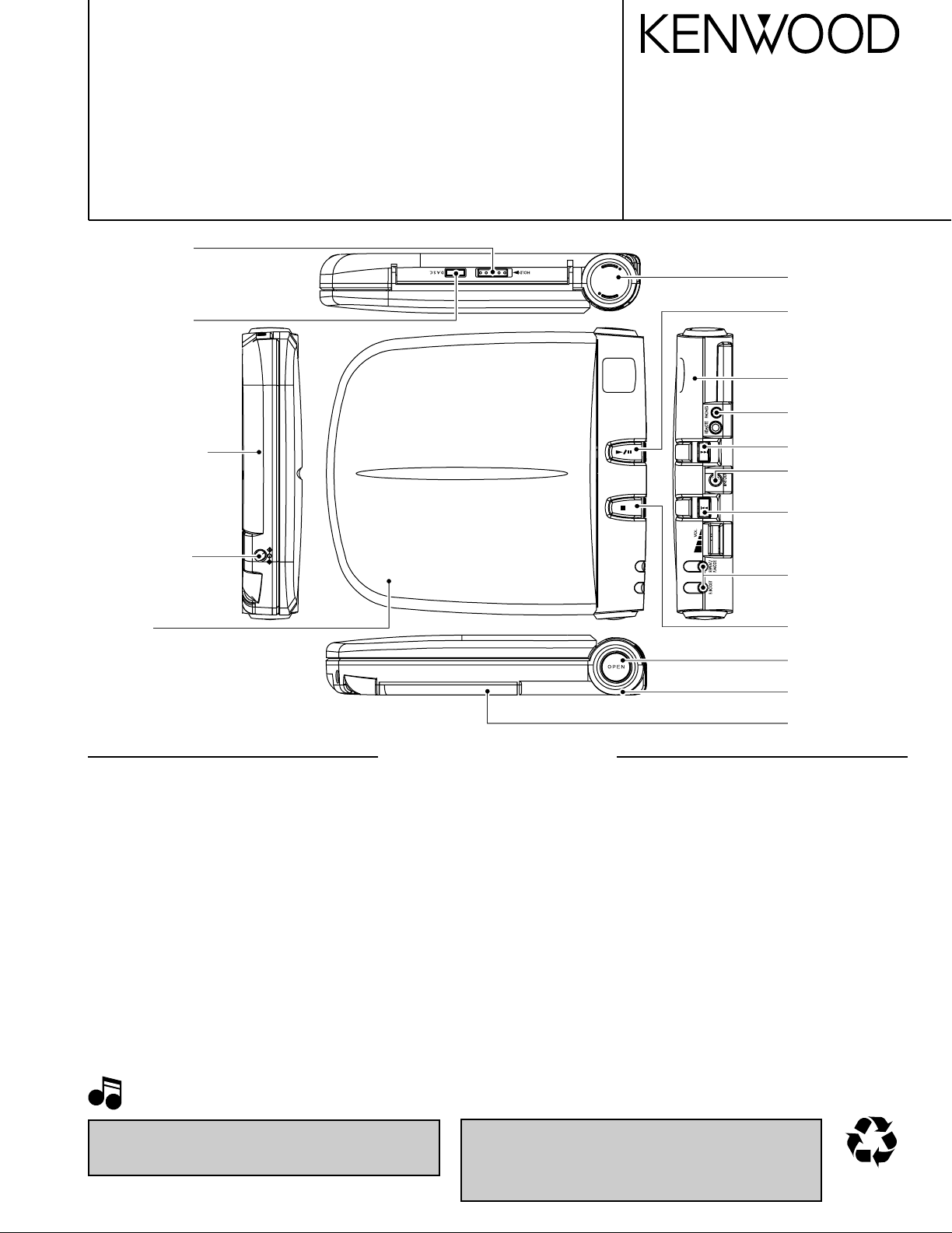
Knob(HOLD)
(K27-2439-08)
Knob(DASC)
(K27-2446-08)
Bottom cabinet *
(A02-)
DC jack
(E03-0356-08)
Cover R *
(A21-)
Knob(PLAY)
(K27-2441-08)
Top cabinet ass'y *
(A02-)
Stereo jack
(E11-0372-08)
Knob(FF)
(K27-2444-08)
Stereo jack
(E11-0354-08)
Knob(REW)
(K27-2443-08)
Knob(REPEAT)
(K27-2440-08)
Door *
(A52-)
*Refer to parts list on page 14 .
Knob(STOP)
(K27-2442-08)
Knob(OPEN) *
(K27-)
Ring L *
(A21-)
Battery cover
(A09-1194-08)
SPECIFICATIONS
Format
System..................................................................................................................................................................Compact disc digital audio system
Laser ..........................................................................................................................................................................................Semiconductor laser
Audio
Frequency response ..............................................................................................................................................................20 Hz to 20 kHz, ±3 dB
PHONES outpuyt level (16ΩW, 1 kHz ) ...............................................................................................................................................9 mW + 9 mW
Line output/impedance .............................................................................................................................................Bass Boost ON : 0.3 Vrms/1 kΩ
Power supply
External DC supply ............................................................................................................................................................................4.5 V to 6 V DC
Rechargeable batteries (NB-130) x 2 or 4....................................................................................................................................................DC 2.4 V
Commercially-available alkaline batteries (LR6/AA) x 2 or 4...........................................................................................................................DC 3 V
Battery life (continuous repeat playback)
(Figures inside parentheses show the performance when the D.A.S.C. is ON.)
Commercially-available alkaline batteries (LR6/AA) x 2 .......................................................................................................Approx. 12 ( 9.5 ) Hours
Commercially-available alkaline batteries (LR6/AA) x 4 ........................................................................................................Approx. 27 ( 23 ) Hours
Rechargeable batteries (NB-130) x 2 ..................................................................................................................................Approx. 7.5 ( 6.5 ) Hours
Alkaline batteries (LR6/AA) x 2 and rechargeable batteries (NB-130) x 2.............................................................................Approx. 20 ( 16 ) Hours
Dimensions (W x H x D) .....................................................................................................................................................150 mm x 28 mm x 137 mm
Weight (net) .............................................................................................................................................................................................. 240 g ( 8.5 oz)
Bass Boost OFF: 0.6 Vrms/1 kΩ
( 5-15/16 " x 1-1/8 " x 5-7/16 ")
In compliance with Federal Regulations, following are reproductions of labels on, or inside the product relating to laser
product safety.
KENWOOD-Corp. certifies this equipment conforms to DHHS
Regulations No. 21 CFR 1040. 10, Chapter 1, Subchapter J.
DANGER : Laser radiation when open and interlock defeated.
AVOID DIRECT EXPOSURE TO BEAM.
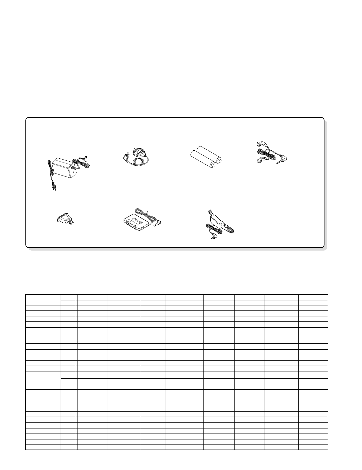
AC adapter (1)
(W08-0658-08): E
(W08-0659-08): T
(W08-0675-08): M
(W08-0679-08): X
(W08-0682-08): KP
AC plug adaptor (1)
(E03-0115-05): M
Car cassette adaptor (1)
(W01-0989-05): DPC-X612
Car battery adaptor (1)
(W01-0921-05): DPC-X612
Rechargeable battery (1)
(NB130)
(W09-1278-08): M4M5M6
Remocon (1)
(A70-1190-05): M4M5M6
Headphone (1)
(W01-0923-05): M4M5M6M7X5X6
(W01-0925-05): E1E2E3E4E5K1
K2M1M2M3M8
M9P1P2P3TX1
X2X4X7X8X9
M7X5X6
M7X5X6
DPC-X311/X517/X612
HOW TO READ THE PARTS LIST
ABBREVIATION OF MODEL AND MASS PRODUCTION'S DESTINATIONS
Australia Canada China England Europe Germany Korea Malaysia
ABB. X P C T E G H I
DPC-X311-L 3
X1 - - - E1 - - -
DPC-X311-H 3
X2 P1 - - - - - -
DPC-X311-Y 3
X3 - - - E2 - - -
DPC-X311-S 3
X4 - - - E3 - - -
DPC-X517-L 5
X5 P2 - T1 E4 - H1 -
DPC-X517-H 5
- - - - - - H2 -
DPC-X517-Y 5
---T2----
DPC-X517-S 5
X6 - - - E5 - H3 -
DPC-X612-L 6
X7 - - - - - - -
DPC-X612-H 6
X8 P3 - - - - - -
DPC-X612-Y 6
---- ----
DPC-X612-S 6
X9 - - T3 E6 - - -
-
Mexico PX/AAFES Russia Scandinavia Shanghai USA Other area
ABB. R Y Q L V K M
DPC-X311-L 3
- - - - - - M1
DPC-X311-H 3
- - - - - - M2
DPC-X311-Y 3
- - - - - - M3
DPC-X311-S 3
---- ---
DPC-X517-L 5
---- -K1M4
DPC-X517-H 5
---- --M5
DPC-X517-Y 5
---- --M6
DPC-X517-S 5
---- --M7
DPC-X612-L 6
---- --M8
DPC-X612-H 6
---- -K2M9
DPC-X612-Y 6
---- ---
DPC-X612-S 6
---- ---
MODEL
MODEL
CONTENTS / ACCESSORIES
Contents
SPECIFICATIONS ........................................Top cover
CONTENTS / ACCESSORIES .................................. 2
DISASSEMBLY FOR REPAIR....................................3
CIRCUIT DESCRIPTION ............................................4
Accessories
PC BOARD ................................................................ 7
SCHEMATIC DIAGRAM ............................................ 9
EXPLODED VIEW ....................................................13
PARTS LIST..............................................................14
2
DPC-X311/X517/X612
1.7x6
(BLK)
ø
1.7x6
(BLK)
ø
1.7x6(BLK)
ø
1.7x6(BLK)
ø
1.7x6(BLK)
ø
1.7x4
ø
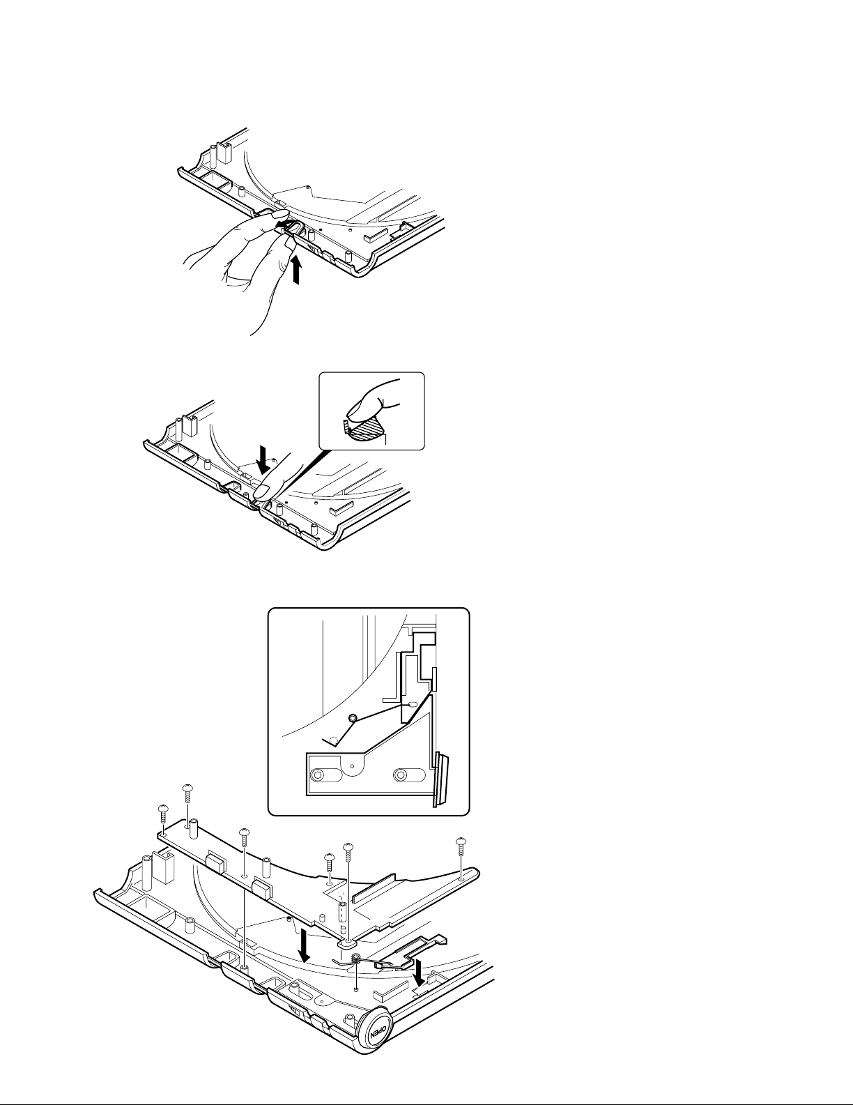
DISASSEMBLY FOR REPAIR
How to Remove Knobs
The PLAY and the STOP keys are available for removal
by pushing and turning them with taking care of bar of
the top cabinet ass'y.
The PLAY and the STOP keys are available for fixation
by hooking and pushing them with taking care of bar of
the top cabinet ass'y.
Door Lock Sping
3

DPC-X311/X517/X612
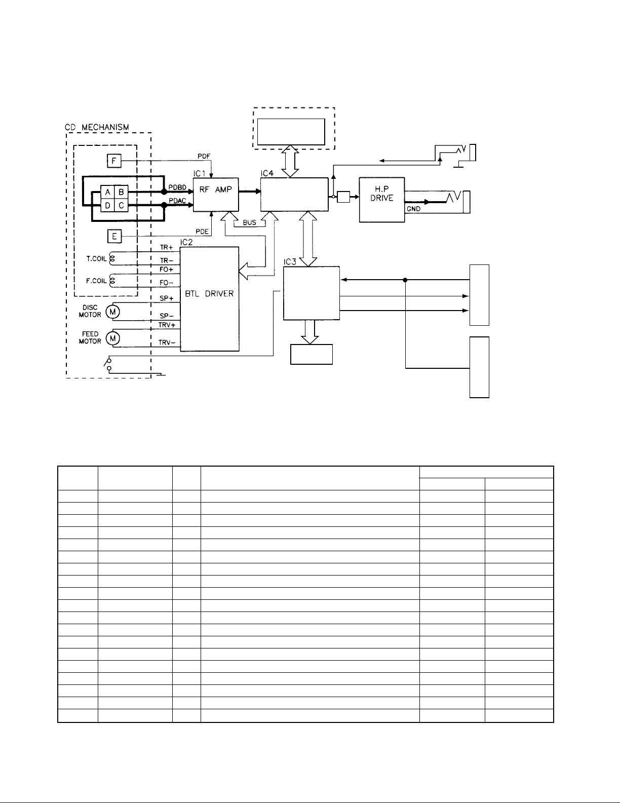
CIRCUIT DESCRIPTION
1. Microprocessor : MN101C439(IC3)
1-1 Pin description
Pin No. Pin Name I/O Description
1-4 COM 0-3 O LCD common output.
5 VLC3 - GND
6,7 VLC2,1 - VDD
8 VDD - VDD
9 OSC2 - Unused.
10 SMCK I External system clock(4.2336MHz).
11 VSS - GND
12 X1 - GND
13 XO - Unused.
14,15 MMODO - GND
16-18 ANO-2 - Unused.
19 KEY0 I Remote control signal input.
20 KEY1 I Key signal input.
21 BATT. I Battery level detection port. LOW BATT
22 NC - Unused.
23 RECHARGE DET I Rechargeable detection port.
24 VREF+ - Power supply(+2.8v).
25 REM DATA O Remote control data output.
26 POWER O Power off control for CD servo driver.
27 REM STATUS - Unused.
28 P03 - Unused.
29 SUBQ I Sub code Q signal input port.
30 SQCK O Sub code clock output port.
31 P06 - Unused.
32 NRESET I Reset signal input for microprocessor.
33 XRESET O Reset output port to DSP IC(IC4). RESET
34 STAT I Status signal input port.
35 MLD O Command load signal output port of microprocessor.
36 MDATA O Command data signal output port of microprocessor.
37 MCLK O Command clock signal output port of microprocessor.
38 BLKCK I Sub code clock signal input.
39 IRQ1 - Unused.
40 DOOR I Door switch detection input. OPEN
41 TEST - Unused.
42 V CONT. O
43 BBS O Bass boost control output. BBS ON
44-46 P42-P44 - Unused.
47 LMT I Limit switch detection input port.
48,49 P46,P47 - Unused.
50 MUTE O Muting control port of audio signal. ON = H
51 LIGHT OUT - Unused.
52 RECHARGE I Detection port for rechargeable battery. BAT CHG ON
53-55 P53,P54,P60 - Unused.
56 AC ADAPTER I Detection port for AC adapter. BATTERY AC ADAP.
57 HOLD I Detection port for hold switch. HOLD ON
58 DASC I DASC switch detection port.
59 DASC1 - Unused.
60 DASC2 - Unused.
61 P66 - Unused.
62 DIG OUT - Unused.
63-68 SEG12-SEG17 - Unused.
63-80 SEG0-SEG11 O Segment control output.
Power voltage change-over
H = DC/DC out 3.0V L = DC/DC out 2.7V
Active
HL
POWER OFF
4
CIRCUIT DESCRIPTION
1-2 Microprocessor periphery block diagram
EXCEPT DPC-X311
IC6
DPC-X311/X517/X612
LMT.
SW
/ / /
AN8838NSB
AN8789FB
16M D-RAM
DSP / DF-DAC
RF
/Anti-shock Memory
MN662780RPS2M
µ-COM
MN101C439
LCD
Lch
VOLUME
IC9
NJM2073M
key input
data
status signal
FROM IC4 (Rch)
Rch
Lch
J105
/ / /
J102
LINE OUT
H. P JACK
DPC-X517
(M/X/H type)only
LCD REMOTE
CONTROL
DPC-X517
(H type)only
3KEY REMOTE
CONTROL
2. DSP IC : MN662780RPS2M(IC4)
2-1 Pin description
Pin No. Pin Name I/O Description
1 DVDD5V - DRAM interface power supply.
2 D0 I/O DRAM data input/output signal 0.
3 D1 I/O DRAM data input/output signal 1.
4 NWE O DRAM writing enable signal.
5 NRAS O DRAM RAS control signal.
6,7 D2,D3 I/O DRAM data signal input/output.
8 NCAS0 O DRAM CAS control signal 0.
9-19 A0-A10 O DRAM address signal 0-10.
20 DVSS2 - Digital ground.
21 DVDD2 - Digital power supply.
22 PWMCK O Disconnected.
23 TRVSTP O Traverse stop signal output.
24 TVD O Traverse control port.
25 PC O Spindle moter on signal output.. ON MODE
26 ECS O Control signal output for spindle motor.
27 TRD O Kick pulse output for tracking driver.
28 FOD O Focus drive output.
29 FBAL O Focus balance adjusting output.
30 TBAL O Tracking balance adjusting output.
ACTIVE
HL
5
 Loading...