

Kenwood CV-100-HU, CV-150-HU Service Manual

STEREO INTEGRATED AMPLIFIER/TUNER
ON/STANDBY
PHONES
INPUT TAPE 2
(MONITOR)
CLOCK
TIMER
MODE
TIMER
SET AUTO
A.MEMO
BAND
TUNING
MODE
MULTI. CONTROL
LEVEL
VOLUME CONTROL
DOWN
UP
ANTENNA
AM
FM 75Ω
GND
CONNECT WITH
POWER AMPLIFIER
SYSTEM
CONTROL
CD
AUX TAPE 1/ MD
IN
IN REC
PLAY
IN
TAPE 2
(MONITOR)
AUDIO
FRONT
REC
REC
PLAY PLAY
MONITOR
OUT
SURROUND
VIDEO
CENTER
SUBWOOFER
UNSWITCHED
LD
/DVD
VCR
L
R
DVD 6CH.INPUT
DIGITAL IN DIGITAL IN
FM 50kHz
AM 9kHz
FM
100kHz
AM 10kHz
50µs
75µs
DEEMPHASIS
CHANNEL
SPACE
C-V100/V150/V300/V350
SERVICE MANUAL
© 1997-6/B51-5323--00 (K/K) 3676
Panel *
(A60-)
Lock terminal board
(E70-0052-05)
Metallic cabinet
(A01-3432-01)
Dressing panel
(A21-1952-03)
Knob *
(K29-)
Phono jack
(E63-0163-05)
Front glass *
(B10-)
Power cord busing
(J42-0083-05)
Knob
(K29-6660-04)
AC power cord *
(E30-)
Miniature phone jack (2P)
(E11-0293-05)
Rectangular receptacle
(E58-0018-05)
Caution : No connection of ground line if disassemble the unit.
Phono jack
(E63-0139-15)x3
Please connect the ground line on rear panel, PCBs, Chassis and some others.
Phono jack *
(E63-0111-05)
C-V300/C-V350 only
* Refer to parts list on page 33.
AC outlet *
(E03-)
Illustration is C-V100.

C-V100/V150/V300/V350
ON/STANDBY
MUTE
VOLUME
ENTER
Setup
DVD/6ch Input
Sound Speaker
C D
Sat.
Tape1
Cable
Reset
VCR1
VCR2
L D
T V
Confirm
Set Up
Return
Input
Source
Main Menu
TapeA
TapeB
Tape1
LD
Tuner
CD
VCR2
VCR1TVSat.Cable
ON/STANDBY
MUTE
VOLUME
ENTER
Setup
DVD/6ch Input
Sound Speaker
C D
Sat.
Tape1
Cable
Reset
VCR1
VCR2
L D
T V
Confirm
Set Up
Return
Input
Source
Main Menu
TapeA
TapeB
Tape1
LD
Tuner
CD
VCR2
VCR1TVSat.Cable
CONTENTS / ACCESSORIES
Contents
CONTENTS / ACCESSORIES ....................................2
CONTROLS.................................................................3
DISASSEMBLY FOR REPAIR.....................................7
BLOCK DIAGRAM.......................................................8
CIRCUIT DESCRIPTION.............................................9
ADJUSTMENT...........................................................14
PC BOARD ................................................................15
SCHEMATIC DIAGRAM............................................23
EXPLODED VIEW .....................................................41
PARTS LIST...............................................................43
SPECIFICATIONS.....................................................54
How to reset the microcomputer
The microcomputer may malfunction (impossibility operation,erroneous display,etc.) when the power cord is unplugged and plugged
in again while the unit is in ON mode with the Key pressed or due
to other external causes.In this case,execute the procedure on the
right to reset the microcomputer and return the unit to the normal
condition.
Accessories (C-V100/300)
FM indoor antenna(1)
(T90-0809-05): MICX type
(T90-0810-05): KPY type
Graphical Remote Control unit(1) *
(C-V300)
(C-V100,only U.S.A. and Canada) *
AM loop antenna(1) (T90-0820-05)
Loop antenna stand(1)
Batteries(R03/AAA) (4)
(C-V300)
(C-V100,only U.S.A. and Canada)
1 Unplug the power cord from the wall outlet.
2 While pressing and holding the POWER or
(ON/STANDBY)key,plug the AC cord into the wall outlet again
• Resetting the microcomputer clears the memory you entered and
returns in to the initial condition when the unit left the factory.
Remote control unit(1) *
(C-V100)
(Except U.S.A. and Canada)
*AC plug adapter (1)
(E03-0115-05)
* Use to adapt the plug on
the power cord to the shape
of the wall outlet.(Accessory
only for regions where use is
necessary)
Batteries(R6/AA) (2)
(C-V100)
(Except U.S.A. and Cana-
Cable tidy(2)
(F07-0102-04)
(C-V150/350)
FM indoor antenna(1)
(T90-0809-05): MICX type
(T90-0810-05): ET type
Remote control unit(1) *
(C-V150)
2
* Refer to parts list on page 33.
AM loop antenna(1) (T90-0820-05)
Loop antenna stand(1)
Batteries(R03/AAA) (4)
(C-V350)
Microphone(1)
(W01-0935-05)
Graphical Remote Control unit(1) *
(C-V350)
(Optional with the C-V150)
Batteries(R6/AA) (2)
(C-V150)
Cable tidy(2)
(F07-0102-04)

C-V100/V150/V300/V350
ON/STANDBY
PHONES
INPUT TAPE 2
(MONITOR)
VOLUME CONTROL
DOWN
UP
AV CONTROL CERTER KC-2
^
2
CLOCK
TIMER
MODE
RDS
PTY
DISPLAY
TIMER
SET
S.DIRECT
ON/OFF
TA/NEWS/INFO.
SET 1
SET 2
VOICE
ACTIVATE
STEREO
DSP
A.MEMO
AUTO BAND TUNING
PTY SELECT
MODE
MULTI.CONTROL
LEVEL
•
OPEN/CLOSE
84
13
5 6 @7
0 !9
#
$
¶
VOICE
ACTIVATE
%
R D S
&
*( ¡™)£¢∞§
AUTO
RDS
EON
PTY
TIMER
NEWS
INFO.
FM
LW
MW
TATP
PRO LOGIC
3 STEREO
DSP
TAPE 2
STEREO
TUNED
MUTE
SLEEP
dB
ms
MHz
kHz
1
2
SOURCE
DIRECT
MEMO
CONTROLS
RDS indicators
(RDS, TP, TA, EON, PTY, NEWS, INFO.)
MEMORY indicator
TIMER
indicators
Broadcast band indicators
Frequency display, input
selector display, preset
channel display, surround
mode display
Display
Decibel indicator
Delay time indicator
Receiving frequency
unit indicators
DSP indicator
3 STEREO
indicator
PRO LOGIC
indicator
TAPE 2 indicator
SLEEP
TIMER
indicator
AUTO tuning
mode/AUTO stereo
reception indicator
STEREO indicator
TUNED indicator
MUTE indicator
SOURCE DIRECT indicator
The keys which have the same names as the controls on the
remote control unit provide the same functions as them.
1 (ON/STANDBY) key
Press to switch between ON and STANDBY.
2 VOICE ACTIVATE indicator
Lights to indicate an occurrence of voice
activation.
3 Remote sensor
4 TIMER SET key
Press to set the timer function.
5 CLOCK key
Press to set the clock.
6 VOICE ACTIVATE ON/OFF key
Press to switch the voice-activation operation ON and OFF.
7 VOICE ACTIVATE SET 1 key
Press to record words for use in voice activation.
8 VOICE ACTIVATE SET 2 key
Press to record words for use in voice activation.
9 STEREO key
0 DSP key
! DOLBY key
STANDBY mode indication
While standby mode is indicated, a small amount of power is supplied to the system to back up the memory. In this mode, the system can be
turned ON by remote control.
With this unit, standby mode is indicated by means of the display panel. The system is in standby mode while the clock display is shown.
@ MODE key
Press to switch various setting modes.
# MULTI.CONTROL key
Press to select various setting modes.
$ GRC transmitter
Outputs the signals transmitted to the
Graphical Remote Control.
% PHONES jack
For use in headphones listening.
^ INPUT SELECTOR key
Press to select the input.
& TAPE 2 (MONITOR) key
For use in monitoring of recording, etc.
* TIMER MODE key
Press to switch the timer modes.
( S.DIRECT key
Press to switch the Source Direct function
) RDS DISPLAY key
¡RDS PTY key
which allows to reproduce the source with
a better quality.
Press to switch the RDS display.
For use during reception of RDS broadcasting.
™RDS TA/NEWS/INFO. key
For use during reception of RDS broadcasting.
£A.MEMO key
Press when using the auto memory function.
¢AUTO key
Press to select the tuning mode.
The auto tuning or manual tuning mode
can be selected.
The input selection display of a source
can be switched to another by pressing
and holding the AUTO key for more than
2 seconds.
∞BAND key
Press to switch the broadcasting band.
§TUNING keys (∧, ∨)
Press to select the radio station to be received.
These keys are also used in the clock adjustment and timer operations.
¶OPEN/CLOSE key
•VOLUME CONTROL knob
3

C-V100/V150/V300/V350
ON/STANDBY
PHONES
INPUT TAPE 2
(MONITOR)
CLOCK
TIMER
MODE
TIMER
SET AUTO
A.MEMO
BAND
TUNING
MODE
MULTI. CONTROL
LEVEL
VOLUME CONTROL
DOWN
UP
AUTO
FM
AM
TAPE 2
STEREO
TUNED
MUTE
SLEEP
dB
ms
MHz
kHz
SOURCE
DIRECT
MEMO
ON/STANDBY
TIMER
1
2
DSP
3 STEREO
PRO LOGIC
POWER
5 $ ^87 9 ! @6 0 #% &
3
4
1
2
*
CONTROLS
For C-V100
Memory indicator
TIMER
indicators
Broadcast band
indicators
Frequency display, input
selector display, preset
channel display, surround
mode display
Display
Decibel indicator
Delay time indicator
Receiving
frequency unit
indicators
DSP indicator
3 STEREO
indicator
PRO LOGIC
indicator
TAPE 2 indicator
SLEEP
TIMER
indicator
AUTO tuning mode/AUTO
stereo reception indicator
STEREO indicator
TUNED indicator
MUTE indicator
SOURCE DIRECT indicator
# BAND key
Press to switch the broadcasting band.
$ TUNING keys (∧, ∨)
Press to select the radio station to be received.
These keys are also used in the clock adjustment and timer operations.
% MODE key
Press to switch various setting modes.
^ MULTI. CONTROL key
Press to select various setting modes.
& VOLUME CONTROL knob
* GRC transmitter
Outputs the signals transmitted to the
Graphical Remote Control.
The keys which have the same names as the controls on the
remote control unit provide the same functions as them.
1 POWER
(ON/STANDBY) key
(U.S.A. and Canada)
Press to switch between ON and STANDBY.
2 (ON/STANDBY) key
Press to switch between ON and STANDBY.
3 STANDBY indicator
4 Remote sensor
5 PHONES jack
6 INPUT SELECTOR key
7 TAPE 2 (MONITOR) key
STANDBY mode indication
For use in headphones listening.
Press to select the input.
For use in monitoring of recording, etc.
8 CLOCK key
Press to set the clock.
9 TIMER MODE key
Press to switch the timer modes.
0 TIMER SET key
Press to set the timer function.
! AUTO key
Press to select the tuning mode.
The auto tuning or manual tuning mode
can be selected.
The input selection display of a source can
be switched to another by pressing and
holding the AUTO key for more than 2
seconds.
@ A.MEMO key
Press when using the auto memory function.
While standby mode is indicated, a small amount of power is supplied to the system to back up the memory. In this mode, the system can be
turned ON by remote control.
4

C-V100/V150/V300/V350
Notes
30°5m30°
30° 30°
ON/STANDBY
MUTE
VOLUME
ENTER
Confirm
Set Up
Return
Input
Source
Main Menu
TapeA
TapeB
Tape1
LD
Tuner
CD
VCR2
VCR1TVSat.Cable
Setup
DVD/6ch Input
Sound Speaker
C D
Sat.
Tape1
Cable
Reset
VCR1
VCR2
L D
T V
Notes
CONTROLS
Controls and indicators
The Graphical Remote Control (GRC) unit provided with the AV CONTROL CENTER can also control KENWOOD cas-
sette decks, CD player and LD player which are connected to it through system control cords. For details of the controllable functions, refer to the instruction manuals of these components.
Perform "Model Type
Setup" of the GRC before
using it.
Segment screen
1 Segment screen
2 Return icon
3 Main Menu icon
4 Cable TV icon
5 Satellite Tuner icon
6 CD icon
7 TV icon
8 Tuner icon
9 VCR 1 icon
0 LD icon
Approximate operating range
Model: GRC-100/150
Infrared system
This area displays the fixed
icons.
Select to return to the previous
display.
Select to change the input
source or select Main Menu 2.
Select to control the cable TV.
Select to control the satellite
tuner.
Select to control the CD player.
Select to control the TV.
Select to control the tuner.
Select to control VCR 1.
Select to control the LD player.
GRC or RC
Infrared ray system
Remote sensor
4
3
5
6
2
1
(
)
¡
! VCR 2 icon
Select to control VCR 2.
@ Tape 1 icon
Select to control cassette deck 1.
# Tape A icon
Select to control cassette deck A.
$ Tape B icon
Select to control cassette deck B.
% Set Up icon
Select to make setup operations.
^ Input Source icon
Select to switch the input
source.
& Sound icon
Select to control the sound-related functions.
* Confirm icon
Select to confirm a setting, etc.
• The input source can be selected using icon 3 or ^.
• Icons 4 to $ are used to select
the component to be controlled.
Infrared remote control
7
8
9
0
!
@#$
Menu screen
( Menu screen
) Mode display
¡ CD icon
™ Reset icon
%
This area displays
the control key
icons and level
information.
The above illustration indicates
the Setup mode.
Select to set up
the CD player.
Select to return to
the "Model Type
Setup"menu screen.
^
&
*
£
Operation keys
£ Joystick key
For use in selecting icons.
The joystick moves in 8 directions.
¢ ENTER key
Press to enter a selection.
∞ VOLUME (UP) control
key
Press to increase the volume
level.
§ VOLUME (DOWN) control key
Press to decrease the volume level.
¶ MUTE key
Press to mute sound temporarily.
• (ON/STANDBY) key
Press to switch the AV CONTROL CENTER and the
components connected to it
through system control cords
between ON and STANDBY.
1. The supplied batteries are intended for use in operation
check. Therefore, their lives may be shorter than ordinary
batteries.
2. When the remote-controllable distance gets shorter than
before, replace all four batteries with new ones.
3. Malfunction may occur if direct sunlight or the light of a highfrequency lighting fluorescent lamp enters the remote sensor. In such a case, change the system installation position
to prevent the malfunction.
4. The GRC display may show erroneous information when the
GRC unit is operated from outside the specified range.
¢
∞
§
¶
•
ª
5

C-V100/V150/V300/V350
3
1
2
9
8
0
7
4
6
5
REMOTE CONTROL UNIT
A B
+10
54321
09876
6
7
8
%
fi
¢4¡
1
¡37
°
2
2
1
ALL INFO.TEXT DISP.
TITLE
SEARCH
MEMO
TUNER
BAND
e STILL STEP
E
A.MONI.
AUTO
MEMORY
RDS
DISPLAY
PTY
SEARCH
DISPLAY
SLEEP
NEXTPREV.
POWER
TIME
CLEAR
P.MODE
CHECK
STEREO
MUTE
SOURCE
DIRECTDSP
LEVEL VOLUME
PRO LOGIC 3 STEREO
MULTI
CONTROL
TEST
TONE
MODE
INPUT
TAPE 2
(MONITOR)
FREEZE
PAL/NTSC
RETURN
TAPE
VIDEO CD
SELECT
P.B.C.
¶REC/ARMO.T.E.
LD
AUTO DIGITAL
CD/VIDEO CD/LD
REPEAT
FRAME/
TIME
PTY
TA/NEWS/INFO.
DISC SKIPEDIT MODE
ALL TEXT
SEARCH
P.CALL
fi%
A B
CONTROLS
Names and functions of the keys
The "RC" remote control unit provided with the AV CONTROL CENTER can also control KENWOOD cassette decks, CD
player and LD player connected to the AV CONTROL CENTER through system control cords. For details of the controllable functions, refer to the instruction manuals of these components.
The RC keys with the same names as the corresponding
keys on the main unit have the same function as the main
unit keys.
1 (POWER) key
Press to switch the AV CONTROL CENTER
and the components connected to it through
system control cords between ON and
STANDBY.
2 A j B switch
Some of the RC keys function in two ways.
The key functions indicated inside ( ) are
usable when this switch is set to B.
Usually set this switch to A. In this manual, the description of a function which requires this switch to be set to B is accompanied with the illustration of .
3 Numeric keys
Use these keys as the numeric key of the
currently selected input source component.
4 TUNER operation keys
BAND key
(RDS DISPLAY key)
MEMOkey
(AUTO MEMORY key)
P.CALL fi:down key
(PTY key)
P.CALL %:up key
(TA/NEWS/INFO. key)
5 LD player operation key
Read the instruction manual of the LD player.
°: CX key
AUTO DIGITAL key
6 AV CONTROL CENTER operation
keys
PRO LOGIC key
3 STEREO key
DSP key
STEREO key
SOURCE DIRECT key
TEST TONE key
MODE key
Use this key to select the setting modes.
MULTI CONTROL LEVEL
∧
: up key, ∨: down key
Use these keys to adjust the tone or set the
surround play.
TAPE 2 (MONITOR) key
INPUT key
Use this key as the input selector key.
MUTE key
Use this key to mute the sound temporarily.
VOLUME %: up key, fi: down key
Use these keys to adjust the volume.
7 Key
SLEEP key
Press when setting the sleep timer.
DISPLAY key
Press to switch the displayed information.
CD/VIDEO CD/LD player operation
8
keys
Read the instruction manuals of the CD player, VIDEO CD player and/or LD player.
TITLE SEARCH key
(A.MONI key)
TEXT DISP. key
(STILL STEP e key)
ALL INFO. key
(STILL STEP E key)
ALL TEXT SEARCH key
(FRAME/TIME key)
EDIT MODE key
DISC SKIP key
(REPEAT key)
1 key
¡ key
4 key (PREV.)
¢ key (NEXT)
6 key
P.MODE key
CHECK key
CLEAR key
TIME key
7 key
9 VIDEO CD player-specific operation
Model: RC-S503/RC-S503
Infrared system
0 Cassette deck operation keys
Read the instruction manual of the cassette deck.
÷ REC/ARM key
8 key
1 key
2 key
7 key
3 key
¡ key
(O.T.E. key)
keys
Read the instruction manual of the VIDEO
CD player.
P.B.C. key
SELECT key
RETURN key
FREEZE key
PAL / NTSC key
Loading batteries
1 Slide open the cover. 2 Insert batteries. 3 Close the cover.
• Insert two AA-size (R6/SUM-3) batteries as indicated by the polarity marking.
6

DISASSEMBLY FOR REPAIR
1
3
4
4
4
4
4
4
2
x2
x2
1. Remove the 1 screw (1), Then pull the slider (2) till last
2. While raise the slider of left side, remove the slider from the bosses (
C-V100/V150/V300/V350
3,4)
7

C-V100/V150/V300/V350
)
()()()(
(
)
)
(
(
)
)
(
+26dB
+39dB
IC3
M
MCLOSE
MOPEN
DOOR2
DOOR1
LIN
RIN
LOUT
ROUT
COUT
LOUTLIN
ROUT
RIN
SIN
SOUT
LV1016LA2786
IC5
SR. REG
+9V
SR. REG
+15V
-15V
SR. REG
+5.6V
SR. REG
SR. REG
-30V
Q4
Q8,18
Q10
Q11
TONE
CTRL
TONE
CTRL
TDA7466
IC7
UNIT
TUNER
MOPEN
MCLOSE
FL
MATRIX
IC7
D11,12
A1
IC6
ED1
+
+
+
+
Q13
+
MONITOR OUT
VCR OUT
LD
VCR I
DVD 6CH INPUT
LD
VCR REC
VCR PLAY
AUX
TAPE2 REC
TAPE1 REC
TAPE2 PLAY
TAPE1 PLAY
CD
IC4
BYPASS
DSP. D/L
DSP. D/L
BYPASS
NJU7311AL
C-V300/V350
NJU7312AL
NJU7312AL
NJU7312AL
NJU7311AL
R CH
ACTIVE VOICE
RS5S830-0020
IC1
DEMO.
RDS
GRN
RED
RECODE2 (INP4)
RECODE1 (INP3)
TUNER
SYNCHRO x2
PROTECTION
MUTE
C.S RELAY
RDSx2 (DATA,CLK)
H.P MUTE
INP2
OUTP6
INP1
CE.RST
RECOGNITION
POWER
RECOGNITION RESULT
REM IN
REM OUT x9
ROTARY ENC x2
KEY SCAN x6
GRID x11
SEGMENT x16
KEY RETURN x4
u-COM
: uPD780205GF031
DOOR2
DOOR1
-6dB
ATT
(for ADP)
-12dB/OCT
FC=100HZ HPF
IC11(1/2)
FC=100HZ HPF
-12dB/OCT
IC11(2/2)
IC10(2/2)
C-V300/V350
IC2(1/2)
+26dB
FLAT AMP
FLAT AMP
IC2(2/2)
FLAT AMP
IC3(1/2)
IC4
FLAT AMP
+26dB
IC3(2/2)
FC=100HZ LPF
-18dB/OCT
AC OUTLET
(UNSWITCHED)
POWER
(+10V)
for DOLBY
for ELE. VOL.
for INPUT SEL.
for u-COM
for FL
PRO LOGIC
(A. & V.)
& PRE AMP.
TUNER UNIT
IC8
IC9
TDA7309
SCL
SDA
IC2(2/2)
IC1(2/3)
IC2(1/2)
IC1(1/3)
IC1(3/3)
SEL x3
DSP x3
VIDEO SEL x2
E.VOL. x2
TUNER UNIT x8
Q18
VOL. ATT
TAPE2/ADP
POWER
H.P. DET
(CLK, DATA, ST)
(CLK, ADTA, ST)
(VMUTE, 1/2)
(CLK, DATA)
TUNER (SD, STEREO, DO)
PLL (DATA, CLK, CE)
RDS SLEVEL
T.MUTE
ST
CK
DATA
Q1
DOOR
-10dB ATT
(forE.VOL)
Q8
Q6
Q5
Q7
Q2
Q1
IC5(1/2)
IC5(2/2)
IC9
Lch
Rch
Cch
SLch
SRch
SWch
DRV.
DRV.
+6dB
+6dB
IC6
NJU2279D
VMUTE
VSEL1
VSEL2
Q1
SOUT
IC10(1/2)
TC9215
+33dB (C-V300/V350)
IC1(1/2)
IC1(2/2)
TO M-A100/A300
IC2
TC9215AP
C-V300/V350
C-V300/V350
TDA7309
TC9215AP
C-V300/V350
C-V300/V350
PRE OUT
LINE IN/PLAY
(AUDIO)
REC OUT
VIDEO IN/OUT
(VISUAL)
P83
OUTP5
KEY
DOOR2
DOOR1
+16dB
FLAT AMP
+16dB
FLAT AMP
C-V100/V150
C-V100/V150
C-V100/V150
C-V100/V150
V150
C-V100/
Q16
C-V100/V150
(C-V300/V350)
: uPD780206GF019
USED
USED
USED
USED
USED
ANT.
C-V100/V300
C-V150/V350
USED
USED
USED
USED
USED
USED
USED
SLch
GND
DGND
SRch
F. RELAY
SWch
CS RELAY
MUTE
RETURN
POWER(DC12V)
PROTECTION
GND
Cch
GND
Rch
GND
Lch
POWER
+5V
FROM u-COM
FROM u-COM
FROM u-COM
+
IC2
IC1(1/2)
IC1(2/2)
Q14
17
1
FROM u-COM
PROLOGIC
DOLBY
BUFFER
LINE
INPUT
SELCTOR
AUDIO
-1.3dB
-1.3dB
-1.3dB
-1.3dB
-1.3dB
-4.9dB
u-COM
REMOTE
VIDEO
SELECTOR
VIDEO
AMP.
HEADPHONE
VOICE
UNFIXED
VOICE
FIXED
PRE OUT
PHONES
NJU7311AL/7312AL
INPUT
6CH
DVD
E.VOL
200mV/47KΩ
200mV/1KΩ
1V/100
1Vp-p/75Ω
DOLBY
SURROUND
(M-A100/A300)
VOICE
ACTIVE
(MIC)
J7
(X14)
(X11)
(X05)
(X08)
X08
(X14)
(X13-752)
(X11)
(X08)
C-V100/V150/V300/V350
(X13-756)
C-V300/V350
(DOOR OPEN/CLOSE MECHA : EXCEPT C-V100)
USED
C-V150/V350
(X11)
Ω
BLOCK DIAGRAM
8

C-V100/V150/V300/V350
CIRCUIT DESCRIPTION
1. New Functions
1-1 Amp section
(a) LCD Remote Control with System Control Code
Display on remote control shows the present condition
of others units;CD player, cassette deck and so.
(b) One Touch Operation
• In power off mode, system will turn on and start to playback if play key on every unit; CD, DECK, DVD, and MD
will be pressed .
• In power off mode, system will turn on and start to open
if open/close key on every unit; CD, DECK (single),
DVD, and MD will be pressed
(c) Voice Activation (C-V150/V350)
In voice activation mode, when system has "KENWOOD" word it will turn on and start to playback CD or
LD player even if power switch is turn off.
Key word will be available of changing any other word.
(d) Automatic Power-off
The system will be turned off if it is turned on by voice
activation and selector keeps position at CD or LD position and system does to stop condition for 30 mints in
CD or LD mode.
1-2 Tuner section
EON(Enhanced Other Network) (C-V150/V350)
• Automatic memory (broadcasting station name with sort
mode), FM station will be morized after RDS station are
done.
• In the case of broadcasting TA(Traffic information),
NEWS(PTY), and INFO(PTY) in same network station,
system will receive TA, NEWS, INFO or normal broardcastings automatically.
2. Backup and Initial Data
Power :off
Main volume :-65dB
Audio selector :tuner
Video selector :vcr
Tape 1/md :tape 1
Ld/dvd(C-V300/V350) :ld
Tape 2/monitor :off
Fl display mode :selector
Source direct :off
Surround mode :stereo
Dolby mode :pro logic
Dsp mode :Arena
Speaker level :0dB
Balance :Center
Input level :0dB
Delay time :20ms
Effect level :3
Tone bass :0dB
Tone treble :0db
Tuning mode :Auto
Preset memory :Test frequency
Last band :FM
Fm last frequency :87.5MHz
Am (mw) last frequency :531kHz
(channel space 9kHz)
:530kHz
(channel space 10kHz)
Lw last frequency :153kHz
Last P.ch :-ch
PTY select mode(C-V150/V350) :off
RDS display mode :frequency
TA/NEWS/INFO :off
Clock :A.M.12:00
Timer :off
Sleep timer :off
Voice activation key word :KENWOOD
Voice activation :on
*Initial setting : While pressing the CD key, plug the power
cord into the ac power outlet.
9

C-V100/V150/V300/V350
REMOCON
u-COM
(X11) IC7
PLL IC
RDS DEMO. IC
ELECTRIC VOL.
TONE CONT.
+10dB ATT.
MUTE
VOICE ACTIVATION
(X05) IC2
(X13) IC2
(X08)Q1,2,5~8,15
(X08) IC7,8,9
SERIAL
COMMUNICATION
ROTARY ENCODER
(VOLUME CONTROL)
DELAY IC
DSP IC
DOOR
OPEN/CLOSE
AUDIO SELECTOR
VIDEO SELECTOR
KEY MATRIX
(X14) S30
(X08) IC5
(X08) IC4
DOOR MECHANISM
(X11) IC1,2
(X08) IC6
FL DISPLAY
(X14) ED1
(X13) IC1
(X14)
SP. RELAY
PROTECTION
POWER
CHIP ENABLE
PHONES DETECT
RESONATOR(X1. MAIN)
X'TAL RESONATOR (X2. TIMMER)
RESET
DOOR AUTOMATIC LIGHTING KEY LED
u-COM
uPD780205GF031
uPD780206GF019
KEY
SCAN
KEY
RETURN
VOICE INPUT
POWER ON
ACTIVE VOICE ON
(X11) IC6
VOICE
SET 1
VOICE
SET 2
CIRCUIT DESCRIPTION
3. Main microprocessor uPD 780205GF031 (X11 : IC6) : C-V100/V300
uPD 780206GF019 (X11 : IC6) : C-V150/V350
3-1 Microprocessor periphery block diagram
3-2 Key matrix No. into : Pin No. of main u-COM
73
KS0 (S.DIRECT) (STEREO) (DSP) (DOLBY)
74
KS1 VOICE ON / OFF DISPLAY (RDS) PTY TA / NEWS / INFO.
75
KS2 MODE MULTI LEVEL @ MULTI LEVEL # (OPEN / CLOSE)
76
KS3 CLOCK SET AUTO MEMORY BAND AUTO
77
KS4 TUNING % TIMER SET INPUT @ INPUT #
78
KS5 TUNING fi TIMER MODE ON / STANDBY TAPE 2 (MONITOR)
KS6
81
KS7 DSW0 / D15 DSW1 / D14 DSW2 / D13 DSW3
82
KS8 DSW4 / D16
• ( ) : C-V300/V350 function
• DSW1 ~ DSW4 : Tuner distinction
• DSW5 : C-V100/V150 or C-V300/V350 Model distinction
• PTY, TA / NEWS / INFO, DISPLAY (RDS) : RDS function model (C-V150/V350)
10
2 KR3 3 KR2 4 KR1 5 KR0

C-V100/V150/V300/V350
CIRCUIT DESCRIPTION
3-3 Pin description
Pin No. Port Name I/O Description
1 Vdd I Power supply (+5V)
2~5 KR3-0 I key return 3 ~ 0
6,7 ENC_VOL1,2 I Encoder pulse detect1, 2
8 /HP_DET I Headphone detect L : Yes
9 /CE I Chip enable L : Enable
10 /RESET I Microprocessor reset L : Reset
11,12 X1,2 I Clock generator
13 IC(vpp) – Connect to Vss
14,15 XT1,2 – Sub clock generator
16 Vdd – Power supply (+5V)
17 /HP_MUTE O Mute of headphones
18 PROTECTION I Protection detection
19 SBUSY I/O Serial data busy
20 SDATA I/O Serial data
21 DSP_CLK O Clock for DSP
22 DSP_DATA O Data for DSP
23 DSP_ST O Strobe for DSP
24 /MUTE O Mute control L : Mute on
25 Avss – GND of a/d converter
26 PLL_DO O Pll do
27 PLL_CE O Chip enable for pll
28 PLL_DATA O Data detection for pll
29 PLL_CLK O Clock for pll
30 /T_MUTE O Mute for tuner L : Mute on
31 /STEREO I Stereo signal detection L : Stereo
32 /SD I Synchro signal detection L : SD detection
33 RDS_SLEVEL I Signal level of rds
34 Avdd – Analog power supply for a/d converter
35 Avref – Reference voltage for a/d converter
36 RDS_CLK I Clock for rds
37 RDS_DATA I Data for rds
38 DOOR_LED O Door led automatic light key
39 REMOCON_IN I Input port of remote control signal
40 Vss – GND
41 +10dB_ATT O +10dB attenuator L : Att on
42 VOL_DATA I/O Electric volume control data
43 INPUT_LEVEL O 0/-6dB switch of input level
44 DOOR_DET1 I Door open detection switch
45 DOOR_DET2 I Door close detection switch
46 Vdd – Power supply (+5V)
47 M_OPEN O Motor open function
48 M_CLOSE O Motor close function
49 CS_RELAY O Center and surround speaker relay control L : C, Sch off
50 F_RELAY O Front and sub-woofer speaker relay control L : L, R, Switch off
51 TC9215 O 2/6ch switch of input L : 2ch
52 REM_RWRREQ O Rewrite request signal of left-right remote control data L : Request
53 REM_PWR I Rewrite in signal of left-right remote control data L : rewrite-in
11

C-V100/V150/V300/V350
CIRCUIT DESCRIPTION
Pin No. Port Name I/O Description
54 REM_REREN I Transmit signal of left-right remote control dat L : Transmission
55~62 INP0-7 O Remote control data bits 0-7
63 VOICE_CTRL O Voice activation/standby led
64 SEL_STB1 O Strobe signal for selector ic
65 SEL_DATA O Data signal for selector ic
66 SEL_CLK O Clock signal for selector ic
67 VOICE_CTRL I Input port of voice activation
68 VOL_CLK O Clock signal for electric volume
69~71 VSEL1-3 O Video selector 1-3
72 POWER O Power relay control
73~78 SEG 11-16 O Display segment control 11-16/key scan 0-5
79 Vload – Connect to pull down resistor
80 SEG10 O Display segment control 10
81 SEG9 O Display segment control 9/key scan 7(tuner selection)
82 SEG8 O Display segment control 8/key scan8(model selection)
83~89 SEG1-7 O Display segment control 1-7
90~100 GRID1-11 O Display grid control 1-11
3-4 DESTINATION LIST OF TUNER
Destination Band
K1 FM 87.5MHz ~ 108.0MHz 100kHz -10.7MHz 50kHz 0 0 0 0
(1700) AM 530kHz ~ 1700kHz 10kHz +450kHz 10kHz
K2 FM 87.5MHz ~ 108.0MHz 100kHz +10.7MHz 25kHz 0 0 0 1
(1610) AM 530kHz ~ 1610kHz 10kHz +450kHz 10kHz
E1 FM 87.5MHz ~ 108.0MHz 50kHz +10.7MHz 25kHz 0 0 1 1
AM 531kHz ~ 1602kHz 9kHz +450kHz 9kHz
E3 FM 87.5MHz ~ 108.0MHz 50kHz +10.7MHz 25kHz 0 1 0 1
(RDS) AM 531kHz ~ 1602kHz 9kHz +450kHz 9kHz
E4 FM 87.5MHz ~ 108.0MHz 50kHz +10.7MHz 25kHz 0 1 1 0
(LW) MW 531kHz ~ 1602kHz 9kHz +450kHz 9kHz
(RDS) LW 153kHz ~ 279kHz 9kHz +450kHz 9kHz
M K2/E1 change only setting "DSW1" 0 0 (Q3, D11) 1
✡ Diode SW (DSWx) : 0 = no diode (static mode, LOW)
Frequency Channel PLL
Range space
(DSW1 = 0 : K2, 1 : E1) X
1 = diode (static mode, HIGH)
X = Transistor SW (0 = OFF/1 = ON)
IF
Frequency
DSW3 DSW2 DSW1 DSW0
Diode SW (X11)
(D13) (D14) (D15)
3-5 MODEL DISTINCTION
• C-V350, 300/C-V150, 100
MODEL
C-V150, 100 0
C-V350, 300 1
DIODE SW
(X11) D16
12

CIRCUIT DESCRIPTION
[TEST MODE]
1. SETTING
SETTING
While depressing the
The display becomes the all lighting, then push a key. The display becomes normal.
@ INPUT
CANCEL POWER OFF (Remove the AC plug from the AC outlet)
2. DESCRIPTION
key, then plug the power cord into AC outlet.
C-V100/V150/V300/V350
OPERATION
KEY
TUNER EXCEPT TUNER REMARKS
1 @ INPUT # ìî 00 87.50 íî CD íî LD íî 6ch INPUT(C-V300/V350 only) í
мммммммо
TAPE 1 íî AUX íî VCR мммммммммм
2 TIMER SET PRESET ch UP PROLOGIC íî 3 STEREO
3 TIMER MODE PRESET ch DOWN
ììî ARENA î JAZZ CLUB ì
ммммм
STADIUM нмммм
4 CLOCK FL lighting ON íî OFF STEREO MUTE ON íî OFF
5 DISPLAY TIMER NO PS
6 PTY
7 TA/NEWS/INFO
8 STEREO STEREO MUTE ON
9 Ÿ
PRO LOGIC ON íî OFF
íî 01 87.50 C-V150/V350
ìì INPUT SELECTOR î OFF, S-LEVELî ON, S-LEVEL ìì C-V150/V350
ммммо TA ммммо NEWS ммммо INFO ììì C-V150/V350
íî OFF EXCEPT C-V100
PRO LOGIC
íî 3 STEREO EXCEPT C-V100
(TEST TONE ON / OFF by AUTO key)
10 A, MEMO FREQUENCY UP
11 AUTO AUTO ON
MODE
12 MODE
íî OFF
Key
≠
BASS DOWNíîUP
≠
TREBLE
≠
LR BALANCE
≠
SW ch
≠≠
INPUT -6dBíî0dB
LEVEL
SOURCE
DIRECT
key
MODE
≠
VOLUME -89dBíî0dB -40dB
≠
SP. SW MINíîMAX 0dB
≠
DELAY 15íî30 20
≠
INPUT -6dBíî0dB -6dBíî0dB 0
≠
EFFECT 1íî53
≠
L. R BALANCE DOWNíîUP LmaxíîRmax CENTER
≠
TONE MINíîMAX FLAT
íî OFF
ON
LEVEL TUNING BAND
STEREO
13
C-V100/V150/V300/V350
No.
ITEM
INPUT
SETTING
OUTPUT
SELECTOR
TUNER/AMP
SETTING
ALIGNMENT
POINTS
ALIGN FOR
FIG.
SELECTOR : FM
1
DISCRIMINATOR
L31↔L32
(E, T only)
(A)
98.0MHz
1kHz, ±40kHz dev
(E, T type)
60dBu (ANT INPUT)
Connect a DC
voltmeter between
port of CN2
AUTO
98.0MHz
L31 (X05-)
0V
(a)
(B)
L32 (X05-)
Minimum
distrotion
2
DISTORTION
(STEREO)
(C)
98.0MHz
1kHz, ±40kHz dev
pilot: ±6kHz dev
60dBu (ANT INPUT)
(B)
AUTO
(98.0MHz)
IFT (W02-)
Mininum
distrotion
(a)
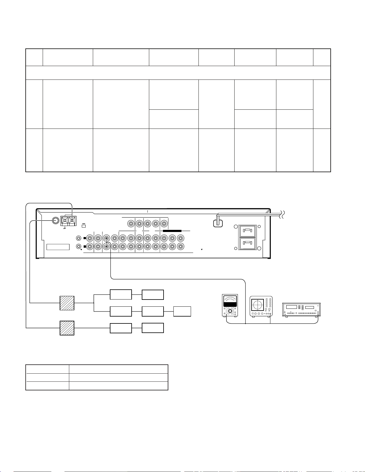
ANTENNA
AM
FM 75Ω
GND
CONNECT WITH
POWER AMPLIFIER
SYSTEM
CONTROL
CD
AUX TAPE 1/ MD
IN
IN REC
PLAY
IN
TAPE 2
(MONITOR)
AUDIO
FRONT
REC
REC
PLAY PLAY
MONITOR
OUT
SURROUND
VIDEO
CENTER
SUBWOOFER
UNSWITCHED
LD
/DVD
VCR
L
R
DVD 6CH.INPUT
DIGITAL IN DIGITAL IN
FM 50kHz
AM 9kHz
FM
100kHz
AM 10kHz
50µs
75µs
DEEMPHASIS
CHANNEL
SPACE
Oscilloscope
Distortion meter
AC voltmeter
Dummy antenna
(B)
(A)
(C)
(D)
AG
AG
FM SG
MPX
AG
FM SG
AM SG
(a)
ADJUSTMENT
ERROR MESSAGE
DISPLAY DESCRIPTION
ERR 1 Main u-com sub clock no output
ERR 2 Main u-com sub clock frequency NG
14
 Loading...