

Page 1

AUDIO/VIDEO STEREO RECEIVER
KR-V6040
INSTRUCTION MANUAL
KENWOOD CORPORATION
Page 2
Introduction
Your choice of this product indicates that you are a devotee
to excellence in sound reproduction.
We appreciate your patronage and take pride in the long tradi
tion of quality components that our company represents.
So that you can get the most out of your unit, we suggest that
you take the time to read through this manual before you hook
up and operate your system. This will acquaint you with oper
ating features and system-connection considerations so that
your listening pleasure will be enhanced right from the start.
You will notice that in all aspects of planning, engineering,
styling, operating convenience and adaptability we have sought
to anticipate your needs and desires.
Keep this rnenuel hendy for future reference.
For your records
Record the serial number, found on the back of the unit, in
the spaces designated on the warranty card, and in the space
provided below. Refer to the model and serial numbers
whenever you call upon your dealer for information or service
on this product.
Model
_______________
Serial Number
________________
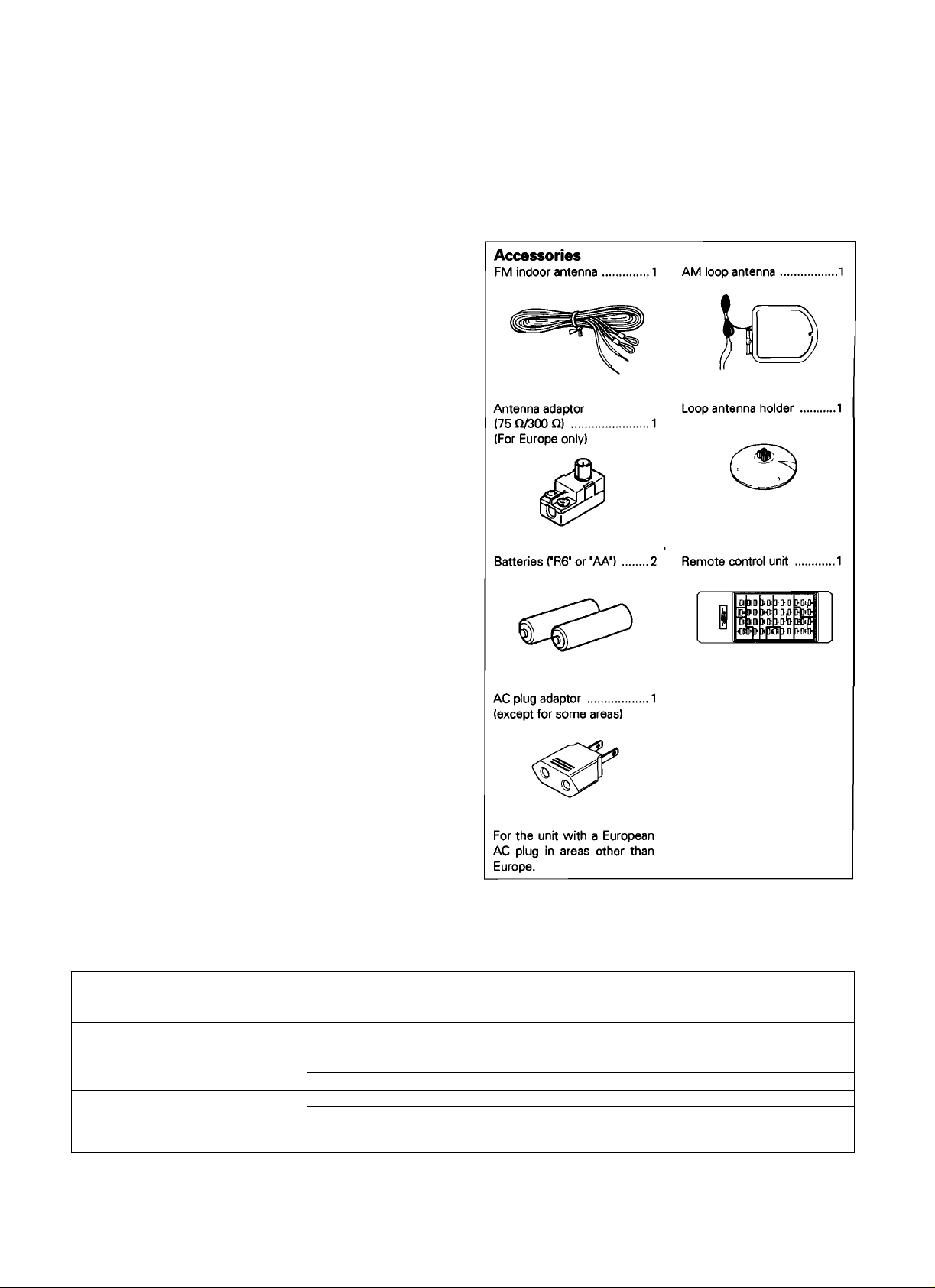
Unpacking
Unpack the unit carefully and make sure that all accessories
are put aside so they will not be lost.
Examine the unit for any possibility of shipping damage. If your
unit is damaged or fails to operate, notify your dealer immedi
ately. If your unit was shipped to you directly, notify the ship
ping company without delay. Only the consignee (the person
or company receiving the unit) can file a claim against the car
rier for shipping damage.
We recommend that you retain the original carton and pack
ing materials for use should you transport or ship the unit in
the future.
For the USA
Note to CATV system installer:
This reminder is provided to call the CATV system installer's
attention to Article 820-40 of the NEC that provides guidelines
for proper grounding and, in particular, specifies that the cable
ground shall be connected to the grounding system of the
building, as close to the point of cable entry as practical.
Contents Caution: Read the pages marked A carefully to ensure safe operation.
Introduction..................................
A Before applying power
A Safety precautions
..........
.................
A IMPORTANT SAFEGUARDS .
System connections
...................
FM DE-EMPHASIS/CHANNEL SPACE switch
System control operation
Controls and indicators
KR-V6040 (En)
..........
.............
....
2
....
3
....
3 Listening to broadcasts
....
4 Operation with video components
....
6 Dolby surround (except for Europe)
.....
9
..
....
10
....
11
Operation of remote control unit
Basic operation
In case of difficulty
A Specifications
..........................................
....................................
........................................
..............
............................
...........
........
..............
..............
..............
..............
..............
..............
..............
12
14
18
20
21
22
24
Page 3
A Caution: Read this page carefully to ensure safe operation.
Before applying power
__________________________________________
For the U.S.A. and Canada
Important!
Units shipped to the U.S.A. and Canada are designed for opera
tion on 120 volts AC only.
CAUTION: TO PREVENT ELECTRIC SHOCK DO NOT USE
THE AC PLUG WITH AN EXTENSION CORD, RECEPTACLE OR
OTHER OUTLET UNLESS THE BLADES CAN BE FULLY IN
SERTED TO PREVENT BLADE EXPOSURE.
For the United Kingdom
important!
Units shipped to the U K. are designed for operation on
240 volts AC only.
The mains plug must be removed from the wall socket prior
to any internal examination.
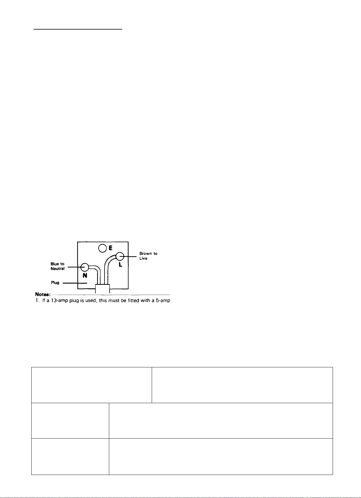
The wires in this mains lead are coloured in accordance with
the following code:
Blue ....................................................... Neutral
Brown .................................................... Live
The wires in this mains lead must be connected to the termi
nals in the plug as follows:
Wire colour Plug terminal marking
Blue
.........................................................
Brown
......................................................
N or Black
L or Red
For Australia and Europe
Important!
Units shipped to Australia are designed for operation on 240 V
AC only.
Units shipped to Europe are designed for operation on 230 V
AC only.
For other countries
Important!
Units shipped to countries other than the above countries are
equipped with an AC voltage selector switch on the rear panel.
Refer to the following paragraph for the proper setting of this
switch,
AC voltage selection
This unit operates on 110-120 or 220-240 volts AC. The AC
voltage selector switch Type A or Type B on the rear panel is
set to the voltage that prevails in the area to which the unit
is shipped. Before connecting the power cord to your AC out
let, make sure that the setting position of this switch matches
your line voltage. If not, it must be set to your voltage in ac
cordance with the following direction.
Note:-------------------------------------------------------------------------------------
Our warranty does not cover damage caused by excessive line
voltage due to improper sptting of the AC voltage selector
switch.
AC voltage selector switch
fuse.
2. If a 3-pin plug with earthing contact is used, no wire must
be connected to the E terminal.
Type A
Type B
Move switch lever to match your line voltage with
a small screwdriver or other pointed tool.
AC110-
120V-
AC 110V-
120V-
!i! Ml!
AC220V- AC240V-
■ AC220V-
240V-
Safety precautions
WARNING: TO PREVENT FIRE OR ELECTRIC SHOCK, DO NOT EXPOSE THIS APPLIANCE
TO RAIN OR MOISTURE.
CAUTION: TO REDUCE THE RISK OF ELECTRIC SHOCK, DO NOT REMOVE
COVER (OR BACK). NO USER-SERVICEABLE PARTS INSIDE, REFER SER
VICING TO QUALIFIED SERVICE PERSONNEL.
THE LIGHTNING FLASH WITH ARROWHEAD SYMBOL, WITHIN AN EQUILATERAL TRIANGLE,
IS INTENDED TO ALERT THE USER TO THE PRESENCE OF UNINSULATED "DANGEROUS VOL
TAGE" WITHIN THE PRODUCT'S ENCLOSURE THAT MAY BE OF SUFFICIENT MAGNITUDE
A
TO CONSTITUTE A RISK OF ELECTRIC SHOCK TO PERSONS.
A
THE EXCLAMATION POINT WITHIN AN EQUILATERAL TRIANGLE IS INTENDED TO ALERT THE
USER TO THE PRESENCE OF IMPORTANT OPERATING AND MAINTENANCE ISERVICING) IN
STRUCTIONS IN THE LITERATURE ACCOMPANYING THE APPLIANCE.
KR-V6040 (En) 3
Page 4
IMPORTANT SAFEGUARDS
A Caution : Read this page carefully to ensure
safe operation.
___________________
Please read all of the safety and operating instructions
before operating this unit. For best results, follow all
warnings placed on the unit and adhere to the operat
ing and use instructions. These safety and operating in
structions should be retained for future reference.
1. Power sources — The unit should be connected
to a power supply only of the type described in the
operating instructions or as marked on the appliance.
2. Power-cord protection — Power-supply cords
should be routed so that they are not likely to be
walked on or pinched by items placed upon or
against them, pay particular attention to cords at
plugs, convenience receptacles, and the point where
they exit from the unit.
Never pull or stretch
the cord.
3. Grounding or polarization — The precautions
should be taken so that the grounding or polariza
tion means of this unit is not defeated.
7. Heat — The unit should be situated away from
heat sources such as radiators, heat registers,
stoves, or other units (including amplifiers) that
produce heat.
8. Electric shock — Care should be taken so that ob
jects do not fall and liquid is not spilled into the en
closure through openings. If a metal object, such as
a hair pin or a needle, comes into contact with the
inside of this unit, a dangerous electric shock may
result. For families with children, never permit chil
dren to put anything, especially metal, inside this
unit.
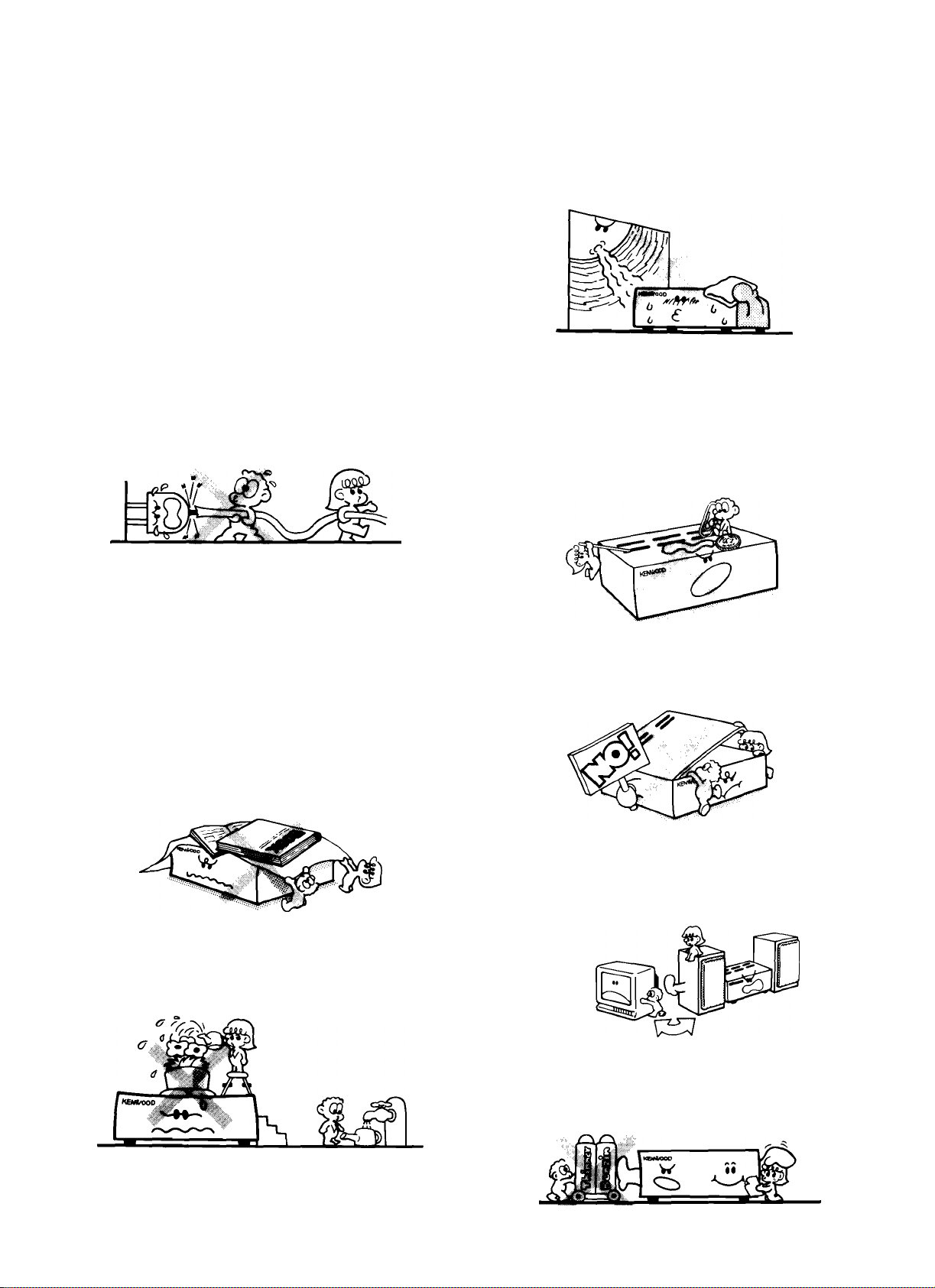
4. Ventilation — The unit should be situated so that
its location or position does not interfere with its
proper ventilation.
To maintain good ventilation, do not put records or
a table-cloth on the unit. Place the unit at least
10 cm away from the walls.
Do not use the unit on a bed, sofa, rug or similar
surface that may block the ventilation openings.
5. Water and moisture — The unit should not be
used near water — for example, near a bathtub,
washbowl, kitchen sink, laundry tub, in a wet base
ment, or near a swimming pool, etc.
9. Enclosure removal — Never remove the en
closure. If the internal parts are touched accidentally,
a serious electric shock might occur.
10. Magnetic fields — Keep the unit away from
sources of magnetic fields such as TV sets, speaker
systems, radios, motorized toys or magnetized
objects.
11. Cleaning — Do not use volatile solvents such as
alcohol, paint thinner, gasoline, or benzine, etc. to
clean the cabinet. Use a clean dry cloth.
6. Temperature — The unit may not function pro
perly if used at extremely low, or freezing tempera
tures. The ideal ambient temperature is above -l- 5°C
(41 °F).
4 KR-V6040 (En)
Page 5
A Caution : Read this page carefully to ensure safe
operation.
12. Carts and stands — An appliance and cart com
bination should be moved with care. Quick stops,
excessive force, and uneven surfaces may cause
the appliance and cart combination to overturn.
13. Nonuse periods — The power cord of the unit
should be unplugged from the outlet when left un
used for a long period of time.
14. Abnormal smell — If an abnormal smell or smoke
is detected, immediately turn the power OFF and pull
out the power cord. Contact your dealer or nearest
service center.
POWER OFF!
ductors, location of antenna-discharge unit, connection
to grounding electrodes, and requirements for the
grounding electrode. See Figure.
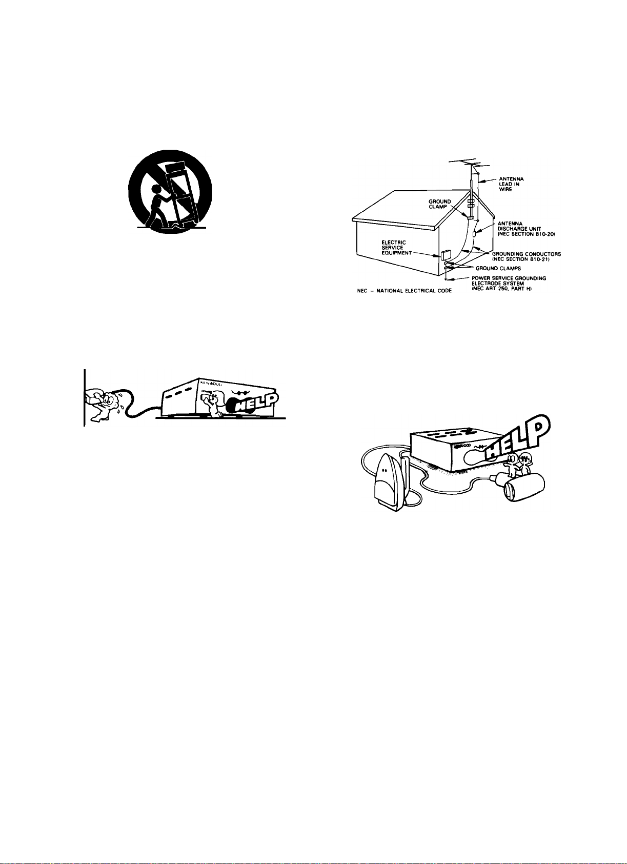
EXAMPLE OF ANTENNA GROUNDING AS PER
NATIONAL ELECTRICAL CODE
18. Power lines — An outdoor antenna should be lo
cated away from power lines.
19. AC outlets — Do not connect other audio equip
ment with a power .consumption larger than that
specified to the AC outlet on the rear panel. Never
connect other electrical units, such as an iron or
toaster, to it to prevent fire or electric shock.
15. Damage requiring service — The unit should be
serviced by qualified service personnel when:
A. The power-supply cord or the plug has been
damaged; or
B. Objects have fallen, or liquid has been spilled into
the unit; or
C. The unit has been exposed to rain; or
D. The unit does not appear to operate normally or
exhibits a marked change in performance; or
E. The unit has been dropped, or the enclosure
damaged.
16. Servicing — The user should not attempt to ser
vice the unit beyond that described in the operating
instructions. All other servicing should be referred
to qualified service personnel.
17. Outdoor antenna grounding — If an outside an
tenna is connected to the receiver, be sure the an
tenna system is grounded so as to provide some
protection against voltage surges and built up stat
ic charges. Section 810 of the National Electrical
Code, ANSI/NFPA 70, provides information with
respect to proper grounding of the mast and sup
porting structure, grounding of the lead-in wire to
an antenna discharge unit, size of grounding con
Notes:--------------------------------------------------------------------------------------------------------------------------
1. Item 3 is not required except for grounded or polarized equipment.
2. Item 17 and 18 are not required except for units provided with entenna terminais.
3. Item 17 complies with UL in the U.S.A.
KR-V6040 (En) 5
Page 6
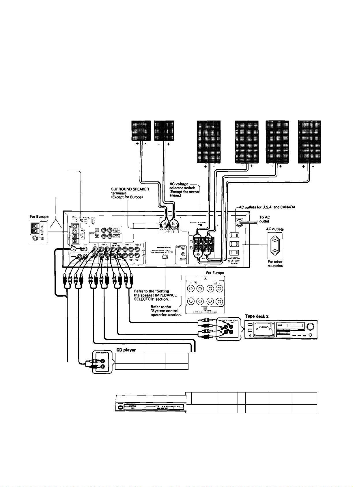
System connections
Make connections as shown in the diagram beiow. When connecting the reiated system components, refer aiso to the
instruction manuais of the reiated components.
Do not piug in the power iead untii ail connections are completed.
■ Connection of audio components
For the connection of video components, please refer to page 20.
FM DE-EMPHASIS/
CHANNEL SPACE switch
(Except for some areas.)
Refer to the 'Antenna
connections* section.
Rear speakers
Right Left
Speaker system A
Right Left
Speaker system B
Right Left
Ho _ o|
a
Turntable
Notes:
1. Connect all cords firmly. If connections are loose there could be loss of sound or noise produced.
2. Do not connect up a power source which is larger than that indicated on the socket at the rear of the unit.
3. When plugging and unplugging connection cords, be sure to first remove the power cord from the AC outlet. Plugging/unplugging connec
tion cords without removal of the power cord can cause malfunctions or damage to the unit.
KR-V6040 (En)
---------
°°°°°
*
rr^
Tape deck 1
|si
-------‘ "
a 0 o o
**
J
—
o[Ln=aJ =
Page 7
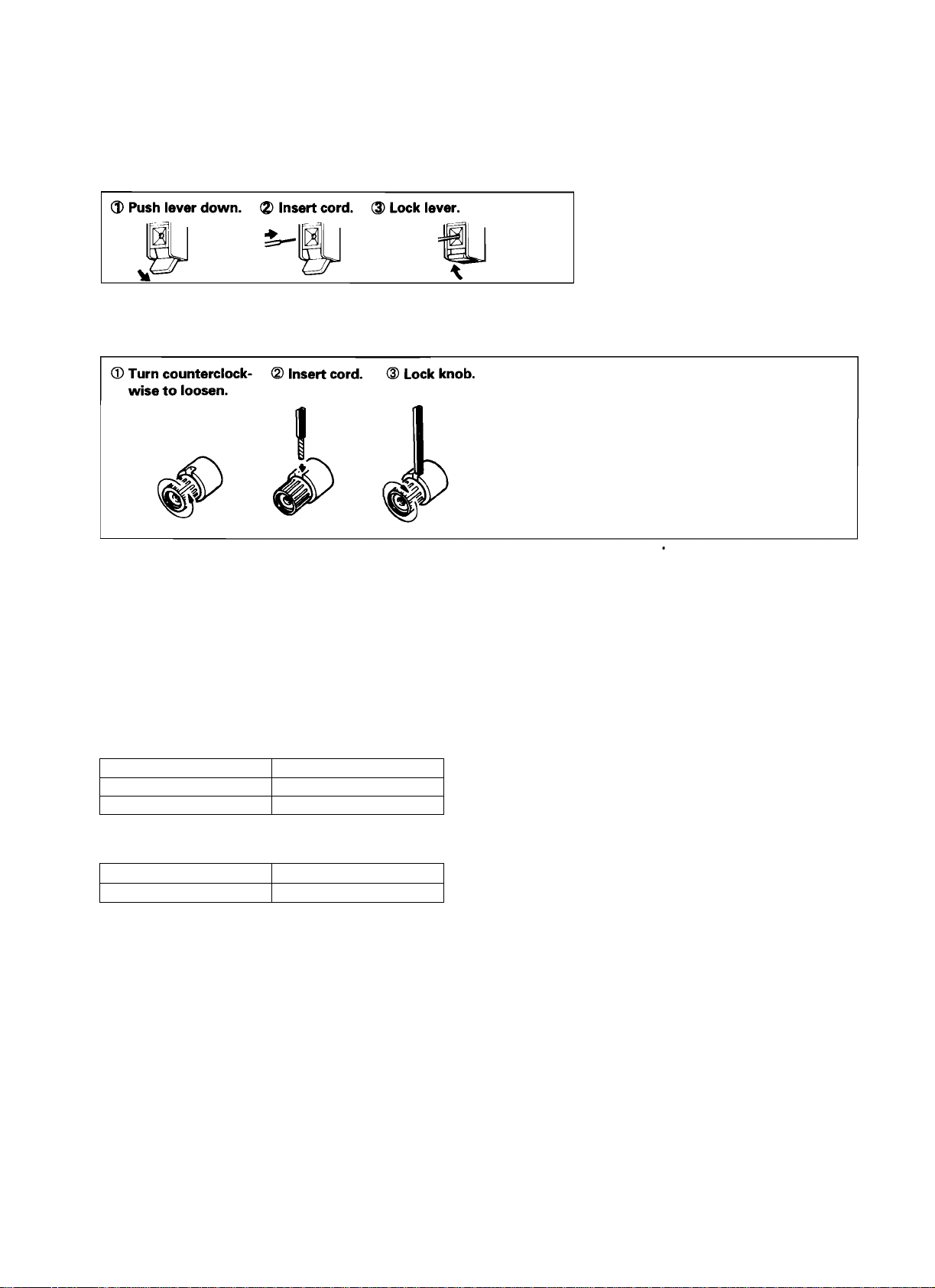
Connection of speakers
Speaker terminals for general
Front speaker terminals for Europe
e Never short-circuit the + and - speaker cords,
e If the left and right speakers are connected inversely or if the
speaker cords are connected with reversed polarity, the sound
becomes unnatural with ambiguous acoustic image positioning.
Be sure to connect the speakers and speaker cords correctly.
Setting the SPEAKER IMPEDANCE SELECTOR
When using the speaker A or speaker B separately
Speaker Impedance Selector position
4il, 6il A or B: LESS THAN 8 il
8il, 16il
When using the speaker A and B simultaneously
Speaker Impedance Selector position
8il, 16il A and B:8ilORMORE
AorB:
LESS THAN 8.<P
AandB:8c> OR MORE
IMPEDANCE SELECTOR
8il OR MORE
Aor B:
80 OR MORE
J]
According to the impedance of the speakers used, set the
SPEAKER IMPEDANCE SELECTOR on the rear panel as shown
in the table.
e When the IMPEDANCE SELECTOR switch is set to ’8 il OR
e During speaker system connection and operation of the
MORE', it is impossible to use the A and B speakers at the
same time.
Therefore, when using the speakers A and B simultaneously,
be sure to set the IMPEDANCE SELECTOR switch to the 'A
and B: 8 il OR MORE' position,
SPEAKER IMPEDANCE SELECTOR, set the POWER key to
OFF.
I
KR-V6040 (En) 7
Page 8
System connections
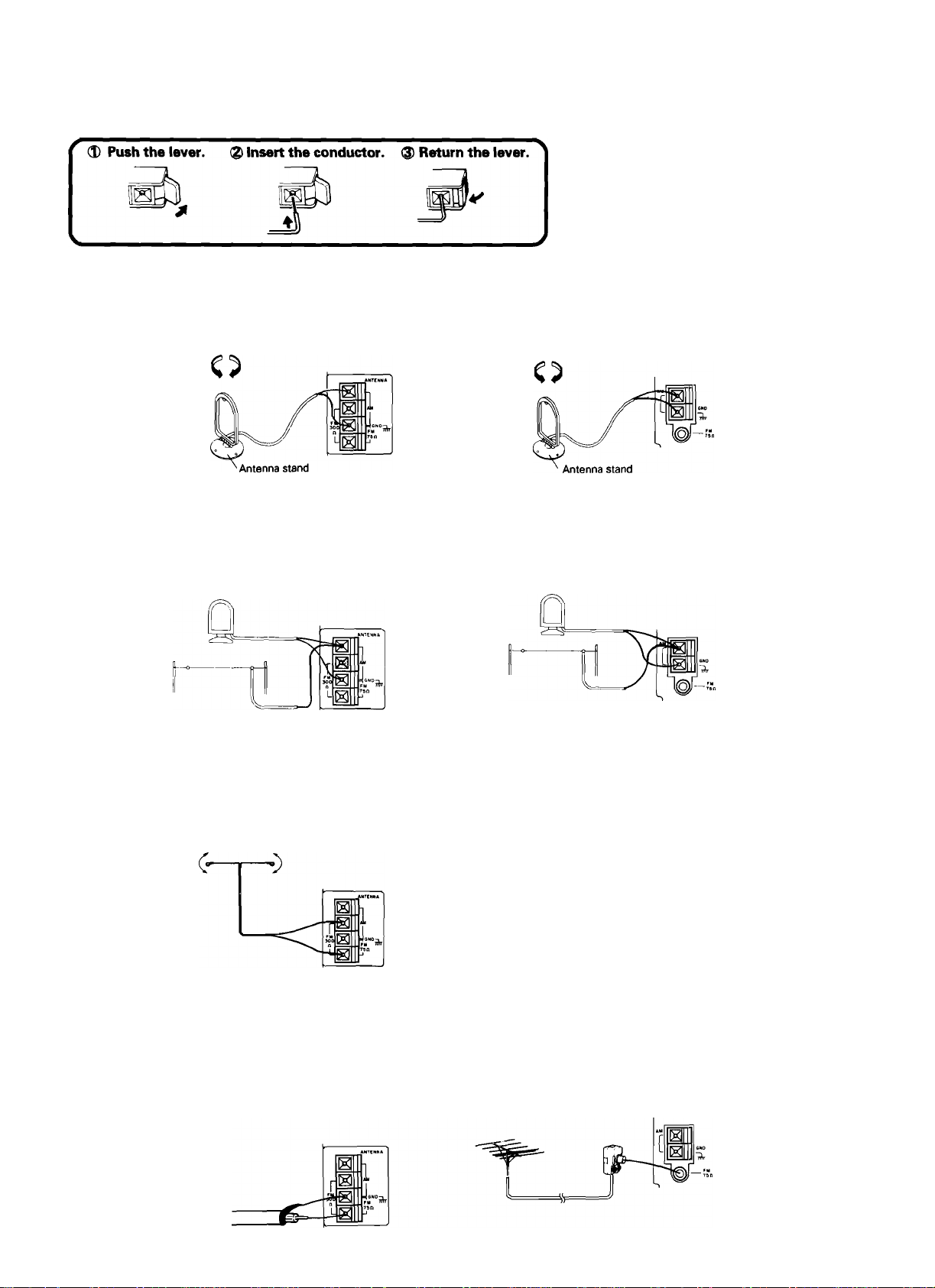
Connection of antennas
AM loop antenna connection
The supplied antenna is for indoor use. Place it as far as possible from the main system, TV set, speaker cords and power cord, and set it
to a direction which provides the best reception.
AM outdoor antenna connection
If the reception is poor when the AM loop antenna is used, distribute a vinyl-coated wire of more than 6 meters outdoors, without discon
necting the loop antenna.
FM indoor antenna connection
The supplied antenna is for indoor use. For stable reception, remove the indoor antenna after installing an outdoor antenna as soon as
possible.
3) Find the position that provides best reception.
@ Fix two ends.
c-
FM outdoor antenna connection
It is recommended to install an exclusive FM outdoor antenna to capture FM broadcasts with high sound quality. Use a coaxial cable for
the connection between the outdoor antenna and FM ANTENNA terminal on the rear panel.
%
8 KR-V6040 (En)
Page 9

75Q coaxial cable connection (For Europe)
® Arrange the coaxial cable as illustrated.
5 14 |a
RG-6 (5C-2V) or RG-59 (3C-2VI
® Insert into the slit on the clip. Fasten the
bands A and B, using a pair of pliers.
Band A
Band B
(mm)
Open the antenna adaptor.
Open the claws with the fingers to
release the lock and pull out the cover.
1
Claw
Close the cover.
Remove the inner conductor from the
groove of pole @ and insert it in the
groove of pole (|).
Pole @
Pole®
Connect the adaptor to the antenna
terminal.
FM DE-EMPHASIS/CHANNEL SPACE switch (Except for some areas)
The FM DE-EMPHASIS/CHANNEL SPACE switch on the rear panel
is set to the correct setting that prevails in the area to which the
unit is shipped. However, if the FM DE-EMPHASIS/CHANNEL
SPACE setting is not matched to the area where the unit is to be
used; for instance, when you move from area 1 to area 2 or vice
versa, desired reception of AM/FM broadcasts is not expected. In
this case, change the FM DE-EMPHASIS/CHANNEL SPACE setting
in accordance with the area corresponding to the table. The FM
DE-EMPHASIS is switched over at the same time.
• When changing the setting of the FM DE-EMPHASIS/CHANNEL
SPACE switch, first disconnect the power cord, then reset the
channel space switch, connect the power cord again, and turn
the power on.
Area
1
U.S.A., Canada, and
South American
countries.
2 Other countries
DEEMPHASIS
50ys
75ps
CHANNEL
SPACE freq.
FM:100 kHz
AM ; 10 kHz
FM ; 50 kHz
AM ; 9 kHz
CHANNEL SPACE
AM FM
A 9 kHz
10 kHz
s;
FM DE
EMPHASIS
75 p s
50 p s
50 kHz
100 kHz
KR-V6040 (En)
Page 10

System control operation
Connection
Using the system control cords provided with KENWOOD system component models, make connections as shown below.
For a cassette deck to
be subject to system
control operation, it
must be connected
to the TAPE 1 jacks.
Turntable
To AC
outlet
System control connection
Be sure to insert the system control cord plugs fully into the
SYSTEM CONTROL terminals.
If the system control cord and audio cords are not connected
properly, the automatic system governing remote control and
system functions will not operate.
By connecting this unit to KENWOOD cassette deck, CD
player, and turntable models equipped with system control
jacks, the following integrated operation features become
available.
1. Automatic play operation
When starting play with the turntable, cassette deck, or CD
player connected to the receiver, press the desired input
selector keys on the receiver. The turntable, cassette deck,
or CD player will automatically enter play mode.
In the same way, pressing the piay key of turntable,
cassette deck, or CD player will automatically switch the
input selector on the receiver to the component on which
the Play key is pressed.
2. Synchro recording
To record the sound from the CD player or turntable on a
tape with the cassette deck, press the CD or PHONO of the
input selector keys and load a CD or record. Set the
cassette deck to rec pause mode, then press the PLAY
(START) key of the CD player or turntable. The cassette
deck will start recording automatically, synchronized with
the CD player or turntable starting play.
3. Remote control
The remote control unit provided with this unit, to which a
KENWOOD system turntable, cassette deck, or CD player is
connected, is equipped with related control keys. The
related components can be controlled used these keys.
10 KR-V6040 (En)
Page 11

Controls and indicators
Page 12

Operation of remote control unit
In addition to the remote control of the receiver unit, the provided remote
controi unit can control a KENWOOD cassette tape deck, CD player, turnta
ble, graphic equalizer, etc., connected via the KENWOOD system control
cords.
Double cassette deck
Loading batteries
Operation procedure
Plug the power cord of the system into an AC wall outlet, and
press the | POWER | key on the remote control unit to turn the
power on.
When the power is turned on, press the key of the source com
ponent to be operated.
When two operation keys on the remote control unit are
pressed successively, press each key securely reserving an
interval of more than 1 second for each press.
Be sure to read the instruction manuals of the components
connected via the system control cords.
Notes:
1. The supplied batteries are intended for use in operation checks. Therefore, their lives may be shorter than ordinary batteries.
2. When the remote-controllable distance becomes gradvally shorter, replace both batteries with new ones.
3. Malfunction may occur if direct sunlight or the light of a high-frequency lighting fluorescent lamp enters the remote control light sensor,
such a case, change the system installation position to prevent the malfunction.
In
12 KR-V6040 (En)
Page 13

I
KR-V6040
(С) 13
Page 14

Basic operation
Basic operation
14 KR-V6040 (En)
Page 15

!
To mute the sound temporarily
Listening through headphones
REMOTE CONTROL ONLY
Insert the headphone plug into the
1
headphones jack.
e Set the SPEAKERS switch so that both speaker systems A
and B are OFF.
2 Adjust the volume.
VOLUME CONTROL
,2l3yT6l6j7,g
Note on LOUDNESS control (For Europe only)
Listening at high volume allows to enjoy dynamic sound, but
human ears tend to feel low frequencies insufficient when
listening at low volume. When the VOLUME CONTROL is set
to a low position, the insufficiency of low frequencies felt by
human ears can be compensated by turning the LOUDNESS
control clockwise.
Enhances low frequencies.
• The effect of LOUDNESS control is less sensible if the
VOLUME CONTROL is set to the ’5’ position or above.
e Be sure to minimize the volume before unplugging the head
phone plug.
Notes:
1. When the TAPE 2 key is set to ON, the source selected with
the INPUT SELECTOR cannot be heard from the speakers.
To listen to a source other than cassette deck 2, be sure to
set the TAPE 2 key to OFF.
2. The source selected with the INPUT SELECTOR is backed
up for a few days even when the power cord is unplugged.
After this period, the tuner is automatically selected when
the power is supplied.
STAND BY mode of POWER switch
When the power cord of this system is plugged into an AC
outlet, the STAND BY indicator lights up regardless of the
ON/OFF setting of the POWER switch. This indicates that a
small amount of current is being supplied to the unit to back up
the memory contents. This mode is referred to as the Stand By
mode. While the STAND BY indicator is lit, the power of the
system can be switched ON/OFF from the remote control unit.
I
KR-V6040 (En) 15
Page 16

Basic operations
Operation of CD DIRECT playback
The digitai sound of Compact Disc features an ideai re
production characteristics, and the sound quaiity pro
vided by CD can be reproduced with ieast degradation
by means of the CD direct playback function.
—
^ Press the CD DiRECT key.
CD DIRECT
1
_____
nri
(
\
J
2 Play the CD player.
PLAy/PAUSE
► /II
Lights up.
CD DIRECT
Listening to CD while recording an
other source
^ Select the source to be recorded.
2 Press the source to be recorded.
Start recording on the cassette deck
connected to the TAPE 1 jacks.
e The CD DIRECT selection is given priority to any other source
being selected by the INPUT SELECTOR.
To cancel the CD DIRECT playback function.
Press the CD DIRECT key again, or select the INPUT SELEC
TOR.
CD DIRECT
r
e CD DIRECT indicator goes off.
Note:
During CD DIRECT or LINE STRAIGHT playback, the tone controls do not function.
16 KR-V6040 (En)
Recording starts.
Press the CD DiRECT key.
CD DIRECT
Lights up.
CD DIRECT
5 Piay the CD piayer.
• No other source can be selected until the cassette deck
recording is stopped.
• The source name on the display remains the same, i.e. the
name of the recorded source.
Page 17

Ordinary tape recording
Tape dubbing (TAPE2 ^ TAPED
Press the TAPE 2 key. ¡„djeator ^
1
Select a source other than TAPE 1.
) /T) c: n «
l' J_.UC.LJ
VIDEO 2 VIDEO 1 TUNEk PHONO CO
Play cassette deck 2 and start recording on
cassette deck 1.
Play cassette deck 2.
e Do not select TAPE 1 while dubbing.
Note:
For the tape-to-tape dubbing procedure using a double-deck
type cassette tape deck, please read the instruction manual pro
vided with the double-deck type cassette tape deck.
Start recording on deck 1.
KR-V6040 (En) 17
I
Page 18

Listening to broadcasts
Receiving broadcast stations and storing them in memory (preset operation)
Press the TUNER key.
1
• Previous reception mode is resumed.
• Pressing the BAND key also set the unit to tuner mode.
TAPE 1 TU
NER PHONO
CJ o n n
...
Select the broadcast band.
3 Select the tuning mode.
e Normally, select the auto mode (with AUTO lighted). ^ Press the key to select the auto (AUTO lighted) or manual (not lighted) mode.
4 Tune the desired station.
To decrease
frequency
• The TUNED indicator lights up when a station is received,
V TUNING A
BAND
To increase
frequency
AUTO
CrP
FM1 -^FM2 -^AM
Every time the BAND key is pressed,
the received frequency band is changed.
Auto tuning mode
Press once. (Tuning
stops automatically when
a station is received.)
rh
Press repeatedly, or press and
hold, until the desired station is
received.
CJ CJ n n
.J ClLJLJ.
p lAUTOl light up.
Manual tuning mode
e Use manual tuning mode when the radio wave is weak and noisy.
At this time, the stereo FM broadcast is received in monaural mode.
5 Store the station in preset memory.
0 Press the MEMORY key.
• Proceed the steps 2 while the MEMORY indicator is lighted.
(2) Press the numeric key.
DIRECT V TUNING A AUTO
CZI I ^ [=1
1 2 3 4 5
CZi CZ3 CJ CZJ cn
6789
nc CJ CD CJ 17^
• Up tolO stations can be preset for each of the FM1, FM2 and AM bands,
e When a station has previously been preset under the numeric key pressed,
the newly preset station replaces the previous station.
18 KR-V6040 (En)
MEMORY I MEMORYlliqhts up for approx. 5sec.
mVI
1 MEMORY Igoes off.n
,r "bbo
0
LJ
Page 19

Receiving a preset station
Direct tuning of radio station
If you know the frequency of the desired station, it can
be received directly by inputting the frequency using
the numeric keys.
Select the broadcast band.
1
Every time the BAND key is pressed,
the received frequency band is changed.
BAND
Select the desired station.
Press the numeric key for the
preset station you want.
DIRECT V TUNING A AUTO
CZI L I cn
1 2 3 ^4 5
CZI CU CD cn □
6 7 8 9
CD CD CD
The frequency of the station received will be displayed.
%
l[Jc: h
БВ.ОО.
Listening to all preset stations in sequence (PRESET CALL)
^ Select the broadcast band.
I—FMl—FM2—AM-
o Every time the BAND key is pressed,
the received frequency band is changed.
BAND
2 Press the DIRECT key.
DIRECT
Input the frequency of the desired station by pressing the numeric keys.
DIRECT V TUNING A AUTO
□ I I CD
1 2 3 4 5
6 7 8 9
CD CD CD CD
1=1 CD □
^ Select the broadcast band.
-FM1-*T=M2—AM-
[Z
Every time the BAND key is pressed,
the received frequency band is changed.
BAND
2 Select the desired station.
P.CALL
e Every time the P.CALL key is pressed, the received preset
station is changed as shown below.
FM1 or FM2 band.
FM 1(1—2—3
...........
10)-^FM2(1-
-2—3..
,.10)
c
AM band
AM(1—2—3—4
..........
9-^10—1—2—3...)
Example of input
Desired station
FM 90 MHz
FM 102.5 MHz
AM 810 kHz
AM 1260 kHz 0. H]. 0,0
Order of pressing numeric keys
[^, [^, [^ (100 kHz space)
0, 0, 0, 0 (50 kHz space)
0- E' 0' 0 (100 kHz space)
0, 0, |T|, [H, 0 (50 kHz space)
0. 00
Last channel memory
When the tuner's band selector is switched or when the input
selector is switched from another source to TUNER, the last re
ceived station is received for each of FM, AM when the receiver
power is switched ON.
I
KR-V6040 (En) 19
Page 20

Operation with video components
For the connections and operations, aiso read carefuily the instruction manuals supplied with the video
components to be connected.
When connect to the KENWOOD LD player having system
control terminal, do not connect anything to the system con
trol terminal of the LD player.
Playback of video tape Recording of video source
^ Switch the power of the monitor TV ON.
2 Press the VIDEO 1 key.
I When an input selector key other than VIDEO is pressed, the
audio input of the selected source will be played in place of
the audio input from VIDEO 1.
VIDEO 1 light up.
I / T Ti c: ri ,
1' -L jjL lj ■
The display shows the
present audio input.
3 Play the VCR.
Connect the video source component to be
1
recorded to the VIDEO 2 jacks.
• A video player deck, video camera, LD player, DBS tuner, etc.,
can be connected.
2 Press the VIDEO 2 key.
I When an input selector key other than VIDEO is pressed, the
audio input of the selected source will be played in place of
the audio input from VIDEO 2.
VIDEO 2 light up.
3 Play the video source component.
I / -r Ti r; n
1' J- M t. u
The display shows the
present audio input.
4 Adjust the volume.
20 KR-V6040 (En)
4 Put the VCR in the record mode.
Page 21

Dolby surround (except for Europe)
■ Operation of Dolby Surround playback
When playing a video software program carrying “ □ □
SURROUND” mark, use the following procedure to ob
tain similar Dolby Surround effect to movie theaters.
SURROUND key
VOLUME CONTROL '
REAR LEVEL knob
INPUT BALANCE knobJ
for Dolby Surround
KR-V6040(En) 21
Page 22

In case of difficulty
What appears to be a malfunction may not always be serious. If your unit should not perform as expected, consult the
table below to see if the problem can be corrected before seeking help from your dealer or service representative.
Remote control unit
Symptom
Remote control operation is not possible.
Amplifier section
Symptom
Sound is not output.
Sound is not output from one of the
speakers.
Sound is not output from the Surround
rear speaker.
A hum noise is generated when the
PHONO input seiector key is pressed.
Cause
Remedy
e Batteries are exhausted. • Replace with new batteries.
e The audio cords and the system control
cords are not connected properly.
e The remote control unit is too far away
from the main system, controlling angle is
too large, or there is an obstacle in
between.
• The source component to be operated
does not contain the analog disk, tape(s)
or CD.
• An attempt is made to play a tape which
is being recorded in the cassette deck.
Cause
• The speaker cords are disconnected.
• The VOLUME is set to the minimum
position.
• The MUTE key of the remote control unit
is set to ON and the point indicator is
blinking.
• Speaker cords are short-circuited.
• The speaker cord is disconnected.
• The BALANCE control is set to an
extreme position.
• The rear-speaker cords are disconnected.
• The Surround play mode has not been
engaged.
• The REAR LEVEL controls are set to the
minimum level.
• The audio cord from the turntable is not
inserted securely into the PHONO jacks.
• The turntable is not grounded.
• Connect properly referring to ‘System
connections'.
• Operate the remote control unit within
the controllable range.
• Place an analog disk, tape(s) or CD in the
source component to be played.
• Wait until the recording is completed.
Remedy
• Connect them properly referring to
‘System connections'.
• Adjust the volume to a proper level.
• Press the MUTE key to OFF.
• Turn the power off, eliminate the
short-circuiting, then turn on the power
again.
• Connect it properly referring to ‘System
connections'.
• Adjust the Left/Right balance.
• Connect them properly referring to
‘System connections'.
• Set the Dolby Surround.
• Adjust the REAR LEVEL controls.
• Insert the audio cord plugs securely into
the PHONO jacks.
• Connect the grounding wire to the GND
terminal on the rear panel.
22 KR-V6040 (En)
Page 23

Tuner section
Symptom
Radio stations cannot be received. • No antenna is connected.
• The broadcast band is not set properly.
• The frequency of the desired station is
not tuned.
A station which was preset cannot be
received by pressing the corresponding
numeric key.
Interference.
Notes:
1. This system is microprocessor-controlled, so malfunction may occur due to external noise or interference noise. In such a case, unplug the
power cord, plug it and turn power on again.
2. Do not use contact cleaners because it could cause a malfunction. Be specially careful against contact cleaners containing oil, for they may
deform the plastic components.
• The preset station belongs to a frequency
that cannot be received.
• The preset memory was cleared because
the power cord had been unplugged for a
long period of time.
• Noise due to ignition noise of an
automobile.
• Noise due to an influence from an electric
appliance.
• Noise due to a nearby TV set.
Speaker protection circuitry
If the speaker cords are short-circuited, the speaker protection
circuitry is activated and the sound is muted. If this occurs,
switch the POWER key to OFF, remove the short-circuit from
the speaker cords, and switch the POWER key to ON again.
Normal operation wili resume.
Cause
• Connect an antenna.
• Set the broadcast band properly.
• Tune the frequency of the desired station.
• Preset a station with a receivable
frequency.
• Preset the station again.
• Install the outdoor antenna apart from the
road.
• Turn off the power of the appliance.
• Install the system more apart from the TV
set.
Manufactured under license from Dolby Laboratories
Licensing Corporation. Additionally licensed under one or
more of the following patents: U.S. numbers 3,632,886,
3,746,792 and 3,959,590: Canadian numbers 1,004,603 and
1,037,877.
"Dolby" and the double-D symbol □□ are trademarks of
Remedy
Dolby Laboratories Licensing Corporation.
For the U.S.A.
FCC WARNING:
This equipment may generate or use radio frequency energy. Changes or modifications to this equipment may cause harmful
interference unless the modifications are explicitly approved in the instruction manual. The user could lose the authority to
operate this equipment if an unauthorized change or modification is made.
Strömbrytarens POWER beredskapsläge
Indikatorn STAND BY lands after nätkabelns anslutning till all
vägguttag, oavsett strömbrytarens POWER till/frànslag. Detta
anger att en liten mängd ström leds till komponenten som stöd
för minnesinnehállet. Detta läge kallas för beredskapsläget.
Strömbrytaren pà fjärrkontrollen kan användas för att slà pà och
av strömmen sä länge indikatorn STAND BY lyser.
Virtanappäimen (POWER) valmiustiia (STAND BY)
Kun laitteen verkkojohto on liitetty pistorasiaan, valmiustilan
merkkivalo syttyy riippumatta virtanäppäimen (POWER)
ásennosla (ON/OFF). Merkkivalo osoittaa, että laitteessa on
hieman virtaa muistin sisältöjen ylläpitoa varíen. Tätä tilaa
kutsutaan valmiustilaksi. Kun valmiustilan merkkivalo (STAND
BY) palaa, laitteen virta voidaan kytkeä ja katkaista
kaukosäätimellä.
Afbrydertastens (POWER) STAND BY funktion
När apparatets str(|>mledning er tilsluttet en stikkontakt, lyser
STAND BY Indikatoren, uanset om der er taendt ved afbryderen
pä apparatet eher ej. Det angiver, at apparatet bliver forsynet
med en ganske lille maengde stri|)m til opret-holdelse af
hukommelsens indhold. Denne funktion kaldes STAND BY. När
STAND BY Indikatoren er taendt, kan str<|)mmen til apparatet släs
til og fra med fjernstyringsenheden.
PÄ/AV-knappens Stand-by funksjon
När str(|>mledningen til dette anlegget er satt i en
vekselstr(|>mskontakt, vii STAND-BY indikatorlampen lyse enten
PÀ/AV-knappen er pä- eller avsiätt. Dette betyr at en viss
mengde str<|>m tilf(|)res anlegget slik at innholdet i minnet ikke
gär tapt. Denne funksjonen kalles Stand-by. När indikatorlampen
for STAND-BY er tent, kan str<|)mmen släs PÄ/AV fra
fjernkontrollen.
KR-V6040 (En) 23
Page 24

Specifications
A Caution: Read this page carefully to ensure safe operation.
Except for Europe
AUDIO SECTION
Rated Power Output
(Front)
(For the U.S.A. & Canada)
100 watts per channel minimum RMS, both channel
driven at 8 O, from 20 Hz to 20,000 Hz with no more
than 0.06% total harmonic distortion. (FTC)
(For other than the U.S.A. & Canada)
(IHF '66) From 20 Hz to 20kHz, 0.06% T.H.D
at8£l............................................ 110W+ now
(Rear)
15 watts per channel minimum RMS, both channels driven
at 8 £1 at 1 kHz with no more than 0.9% total harmonic dis
tortion.
Total Harmonic Distortion
(1 kHz, 8£1)......................................................0.03% at SOW
Input Sensitivity/Impedance
PHONO (MM) ....................................................2.5mV/47k£l
CD, TAPE, VIDEO............................................200 mV/47 k£2
Frequency Response
CD
........................................
Signal to Noise Ratio (IHF-A)
PHONO (MM) ........................................78 dB for 5 mV input
CD, TAPE, VIDEO
Tone Controls
BASS........................................................± 10 dB (at 100 Hz)
TREBLE ...................................................+ lOdB (at 10 kHz)
...........................
VIDEO SECTION
VIDEO Inputs/Outputs
......................
FM TUNER SECTION
Tuning Frequency Range
Antenna Impedance
Sensitivity (IHF)
50 dB Quieting Sensitivity
MONO............................................ 16.2 dBf (3.5 pV at 75 £1)
STEREO
Signal to Noise Ratio at 65 dBf (IHF)
MONO..............................................................................79 dB
STEREO
Total Harmonic Distortion at 1,000 Hz (IHF)
MONO.............................................................................. 0.3%
STEREO ......................................................................... 0.5%
Selectivity (IHF ±400 kHz)
Stereo Separation (IHF at 1 kHz)
Frequency Response
........................................
........................................................................
.......
..............................
..........
AM TUNER SECTION
Tuning Frequency Range
9 kHz step
10 kHz step
(The U.S.A. and Canada) .................... 530 kHz-1,700 kHz
Usable Sensitivity
Signal to Noise Ratio .......................................................50 dB
Total Harmonic Distortion................................................. 0.5%
Selectivity...........................................................................23 dB
...........................................
.........................................
........................................
GENERAL
Power Consumption ... .3A (The U.S.A. and Canada Models)
Dimensions
Weight (Net) .....................................................10.2 kg (22.5 lb)
...........................
10 Hz ~ 50 kHz +0 dB, -3 dB
100 dB for 200 mV input
1 Vp-p, 75 £1 unbalanced
........................
300 £1 balanced & 75 £1 unbalanced
.................................................
......................................
30 Hz-15 kHz h-0.5 dB, -2.0 dB
440 (W) x 143 (H) x 398 (D) mm
(17-5/16‘) X (5-5/8") X (15-11 /16“)
87.5 MHz~108 MHz
10.8 dBf (0.95 pV at 75 £1)
38.2 dBf (45 pV at 75 £1)
73 dB
53 dB
40 dB
531 kHz -1,602 kHz
530 kHz - 1,610 kHz
12 pV/(400 pV/m)
230 W (I EC) (Others)
For Europe
AUDIO SECTION
Rated power output
(lEC) from 63 Hz to 12,500 Hz
0.7% T.H.D. at8£l.....................................110W+ 110W
(DIN) 1,000 Hz at 8 £1.................................. 120W+120W
at4£l
...................................
Total Harmonic Distortion
(1 kHz, 8 £1)....................................................0.03% at 50 W
Input Sensitivity/Impedance
PHONO (MM)
CD, TAPE, VIDEO
Frequency Response
CD
........................................
Signal to Noise Ratio (DIN weighted, at 50 mW output)
PHONO (MM)
CD, TAPE, VIDEO
Tone Controls
BASS .......................................................+ 10 dB (at 100 Hz)
TREBLE ...................................................tlOdB(atlOkHz)
...................................................
...........................................
10 Hz-50 kHz +0dB,-3dB
.................................................................
..........................................................
100 W+ 100 W
2.5mV/47k£l
200 mV/47 k£l
57 dB
58 dB
VIDEO SECTION
VIDEO Inputs/Outputs
.....................
1 Vp-p, 75 £1 unbalanced
FM TUNER SECTION
Tuning Frequency Range
Antenna Impedance
Sensitivity (DIN)
(MONO)
(STEREO) .......................................................................40 pV
Total Harmonic Distortion
(DIN at 1 kHz, 65.2 dBf input)
MONO ...........................................................................0.15%
STEREO
Signal to Noise Ratio (DIN weighted at 1kHz, 65.2 dBf input)
MONO .............................................................................66 dB
STEREO
Selectivity (DIN ±300 kHz)................................................53 dB
Stereo Separation (DIN at 1 kHz) .....................................40 dB
Sub carrier suppression (DIN).......................50 dB (at 19 kHz)
Frequency Response
........................................................................
........................................................................
........................................................................
......................
.................
.......
.'.
30 Hz - 15 kHz +0.5 dB, -2.0 dB
87.5 MHz - 108 MHz
...................
75 £1 unbalanced
1.2 pV
0.3%
61 dB
60 dB (at 38 kHz)
AM TUNER SECTION
Tuning Frequency Range
Usable Sensitivity
Signal to Noise Ratio........................................................50 dB
Total Harmonic Distortion
Selectivity..........................................................................23 dB
........................................
.......................
..............................................
531 kHz - 1,602 kHz
12 pV/(400 pV/m)
0.5%
GENERAL
Power Consumption
Dimensions ...........................440 (W) x 147 (H) x 398 (D) mm
Weight (Net).......................................................................9.9 kg
.....................................................
230 W
AC outlet
For U.S.A. and Canada
SWITCHED
For U.S. military
SWITCHED.........................................3 Total (200 W max.)
For other countries
SWITCHED
Note:
KENWOOD follows a policy of continuous advancement in
development. For this reason specifications may be changed
without notice.
..............................
.................................................
3 Total (200 W 1.6A max.)
1 (200 W max.)
24 KR-V6040 (En)
 Loading...