

Kenmore Elite 14116680, 14117680 Owner’s Manual
Owner's Manual
E L I T E
Liquid Propane Gas Grill
Model 141.16680
,®
Natural Gas
Model 141.17680
Grill
WARNING:
Read this Owner's Manual carefully and be sure
your gas grill isproperly assembled, installed and
maintained. Failure to follow these instructions
could result in serious bodily injury and/or property
damage. This gas grillis intended for outdoor use
only and is not intended to be installed in or on
recreational vehicles or boats.
Note to Installer: Leave this Owner's Manual
with the consumer after delivery and/or installation.
Note to Consumer: Leave this Owner's Manual
in a convenient place for future reference.
Sears, Roebuck and Co.,
Hoffman Estates, IL 60179 U.S.A.
PS0103054B - Date: 2002/12/16

Warranty ..................................................... 2
Safety Instructions ..................................... 2
Hardware ............................................................ 6
Parts Diagram and Lists ........................ 7
Assembly Instructions ............................... 10
Lighting Instructions .................................. 18
Cleaning and Maintenance Instructions .... 20
Frequently Asked Questions .................. 22
Cooking Instructions ................................ 23
Cooking Guide and Recipes ................ 24
/_ WARNING
Combustion byproducts produced when using
this product contain chemicals known to the
State of California to cause cancer, birth
defects, or other reproductive harm.
WARNING
Failure to comply with these instructions
could result in a fire or explosion that
could cause serious bodily injury, death, or
property damage.
/_ WARNING
Your grill will get very hot. Never lean over
the cooking area while using your grill. Do not
touch cooking surfaces, grill housing, Lid or any
other grill parts while the grill is in operation, or
until the grill has cooled down after use.
For the Lifetime of this Kenmore Elite Grill, Sears
will repair or replace, at our option, any Exterior
Stainless Steel orAluminum Casting Parts (except for
paint loss).
Full 2-Year Warranty on Grill:
For 2 years from the date of purchase Sears will repair
or replace, at our option, any grill part (except for paint
loss, rusting and ignitor battery) that is defective in
material or workmanship.
Limited 3 Year Warranty on Selected Grill Parts:
From 2 years after the date ofpurchase for a 3-year
period, Sears will replace Flame Tamers, Cooking
Grids, Burners and All Other Parts (except for ignitor
battery) if they are defective in material or
workmanship. You will be charged for labor.
Warranty Service
Warranty service is available by contacting the ®
nearest Sears Service Center at 1-800-4-MY-HOME
Warranty Restrictions
• This warranty is void if grill is used for com-
mercial or rental purposes.
• This warranty applies only when the grill is
used in the United States.
• This warranty gives you specific legal rights,
and you may also have other rights which vary
from state to state.
Sears, Roebuck and Co., Dept. 817WA,
Hoffman Estates, IL 60179
Failure to comply with these instructions
may result in serious bodily injury.
FOR YOUR SAFETY
1. Do not store or use gasoline or other flam-
mable material and liquids in the vicinity of this
or any other appliance.
2. ALP cylinder not connected for use must not
be stored in the vicinity of this or any other
appliance.
FOR YOUR SAFETY
If you smell gas:
1. Shut off gas to the appliance.
2. Extinguish any open flame.
3. Open Lid.
4. If odor continues, immediately call your gas
supplier or your fire department.
IMPORTANT: Your Kenmore LP Gas Grill cannot
be converted to use Natural Gas. Attempting to do
so is extremely hazardous and will also void the
grill warranty.
Grill Installation Codes
This gas grill must be installed in accordance with
all local codes. In areas without local codes, follow
the latest edition of the National Fuel Gas Code
ANSI Z223.1. and National Electrical Code ANSI/
NFPA 70 In Canada, installation must conform to
standard CAN/CGA lb149.1 or 1-b149.2 (Installation
Code for Gas Burning Appliances and Equipment)
and all local codes.
Correct LP Gas Tank Use
LP gas grill models are designed for use with a
standard 20 lb. Liquid Propane Gas (LP gas) tank,
not included with grill box. Never connect your gas
grill to an LP gas tank that exceeds this capacity.
A tank of approximately 12 inches in diameter by
2
©Sears, Roebuck and Co.
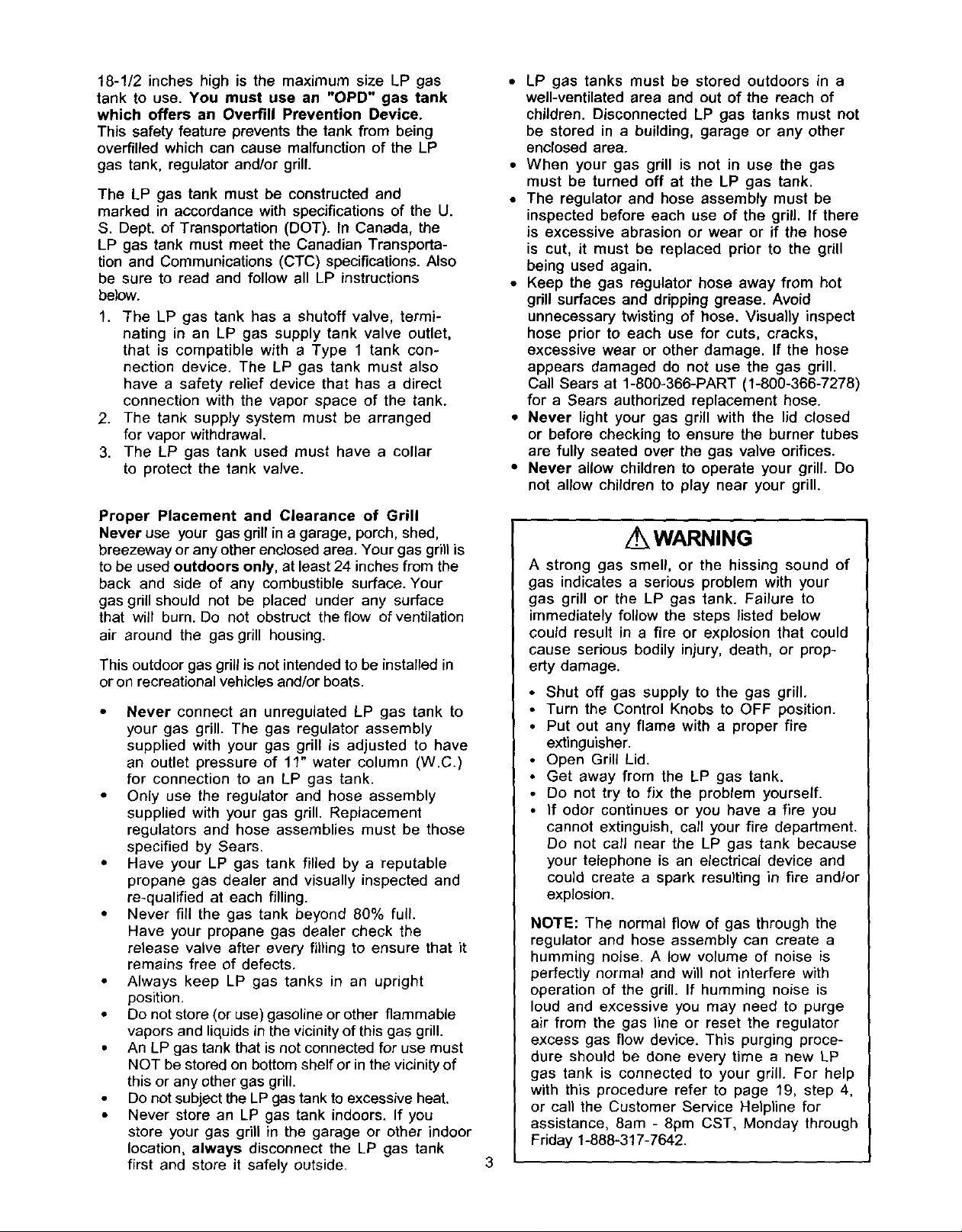
18-1/2incheshighis the maximumsizeLPgas
tankto use. You must use an "OPD" gas tank
which offers an Overfill Prevention Device.
This safety feature prevents the tank from being
overfilled which can cause malfunction of the LP
gas tank, regulator and/or grill.
The LP gas tank must be constructed and
marked in accordance with specifications of the U.
S. Dept. of Transportation (DOT). In Canada, the
LP gas tank must meet the Canadian Transporta-
tion and Communications (CTC) specifications. Also
be sure to read and follow all LP instructions
below.
1. The LP gas tank has a shutoff valve, termi-
nating in an LP gas supply tank valve outlet,
that is compatible with a Type I tank con-
nection device. The LP gas tank must also
have a safety relief device that has a direct
connection with the vapor space of the tank.
2. The tank supply system must be arranged
for vapor withdrawal.
3. The LP gas tank used must have a collar
to protect the tank valve.
Proper Placement and Clearance of Grill
Never use your gas grill in a garage, porch, shed,
breezeway or any other enclosed area. Your gas grill is
to be used outdoors only, at least 24 inches from the
back and side of any combustible surface. Your
gas grill should not be placed under any surface
that will burn. Do not obstruct the flow of ventilation
air around the gas grill housing.
This outdoor gas grill is not intended to be installed in
or on recreational vehicles and/or boats.
• Never connect an unregulated LP gas tank to
your gas grill. The gas regulator assembly
supplied with your gas grill is adjusted to have
an outlet pressure of 11" water column (W.C.)
for connection to an LP gas tank.
• Only use the regulator and hose assembly
supplied with your gas grill. Replacement
regulators and hose assemblies must be those
specified by Sears.
• Have your LP gas tank filled by a reputable
propane gas dealer and visually inspected and
re-qualified at each filling.
• Never fill the gas tank beyond 80% full.
Have your propane gas dealer check the
release valve after every fil_ing to ensure that it
remains free of defects.
• Always keep LP gas tanks in an upright
position.
• Do not store (or use) gasoline or other flammable
vapors and liquids in the vicinity of this gas grill.
• An LP gas tank that is not connected for use must
NOT be stored on bottom shelf or in the vicinity of
this or any other gas grill.
• Do not subject the LP gas tank to excessive heat.
• Never store an LP gas tank indoors. If you
store your gas grill in the garage or other indoor
location, always disconnect the LP gas tank
first and store it safely outside.
• LP gas tanks must be stored outdoors in a
well-ventilated area and out of the reach of
children. Disconnected LP gas tanks must not
be stored in a building, garage or any other
enclosed area.
• When your gas grill is not in use the gas
must be turned off at the LP gas tank.
• The regulator and hose assembly must be
inspected before each use of the grill. If there
is excessive abrasion or wear or if the hose
is cut, it must be replaced prior to the grill
being used again.
• Keep the gas regulator hose away from hot
grill surfaces and dripping grease. Avoid
unnecessary twisting of hose. Visually inspect
hose prior to each use for cuts, cracks,
excessive wear or other damage. If the hose
appears damaged do not use the gas grill.
Call Sears at 1-800-366-PART (1-800-366-7278)
for a Sears authorized replacement hose.
• Never light your gas grill with the lid closed
or before checking to ensure the burner tubes
are fully seated over the gas valve orifices.
• Never allow children to operate your grill. Do
not allow children to play near your grill.
WARNING
A strong gas smell, or the hissing sound of
gas indicates a serious problem with your
gas grill or the LP gas tank. Failure to
immediately follow the steps listed below
could result in a fire or explosion that could
cause serious bodily injury, death, or prop-
erty damage.
• Shut off gas supply to the gas grill.
• Turn the Control Knobs to OFF position.
• Put out any flame with a proper fire
extinguisher.
• Open Grill Lid.
• Get away from the LP gas tank.
• Do not try to fix the problem yourself.
• If odor continues or you have a fire you
cannot extinguish, call your fire department.
Do not call near the LP gas tank because
your telephone is an electrical device and
could create a spark resulting in fire and/or
explosion.
NO'rE: The normal flow of gas through the
regulator and hose assembly can create a
humming noise. A low volume of noise is
perfectly normal and will not interfere with
operation of the grill. If humming noise is
loud and excessive you may need to purge
air from the gas line or reset the regulator
excess gas flow device. This purging proce-
dure should be done every time a new LP
gas tank is connected to your grill. For help
with this procedure refer to page 19, step 4,
or call the Customer Service Helpline for
assistance, 8am - 8pm CST, Monday through
Friday 1-888-317-7642.

Figure 1 (Natural gas model only)
IMPORTANT: your Kenmore Natural Gas Grill cannot
be converted to use LP Gas. Attempting to do so
is extremely hazardous and will also void the grill
warranty.
Your natural gas grillis designed to operate on
natural gas only, at a pressure of 7" water column
(W.C.) (1/4 psi or 1.75 kpa), regulated at the
residential meter. Check with your gas utility
company for local gas pressure and with your
local municipality for building code requirements. If
your residential gas line pressure has not been
regulated to 7" W.C., contact your local gas utility
company for professional assistance.
It is recommended that a ShutoffValve be installed
at the gas supply source outdoors. Install at a point
after the gas pipe exits the outside wall and before
the quick-disconnect hose, or install it at the point
before the gas line piping enters the ground.
See Fig. 1.
• Pipe sealing compound or pipe thread tape resistant
to the action of natural gas must be used on all male
pipe threads when making the connection.
Disconnect your gas grill from fuel source when
the gas supply is being tested at high pressures.
This gas grill and its individual shutoff valve must
be disconnected from the gas supply pipe system
during any pressure testing of that system at
pressure in excess of 1/2 psi (3.5kpa).
TO GRILL
/
MALE
FITTING
OUTSIDE
WALL
\
LOCKING
QUICK
DISCONNECT
GAS SUPPLY
INSIDE
WALL
SHUT OFF
Turn off your gas grill when the gas supply is
being tested at low pressures. The grill must be
isolated from the gas supply pipe system by
closing its individual manual shutoff valve during
any pressure testing of the gas supply pipe
system at pressures equal to or less than 1/2 psi
(3.5kpa).

CAUTION: Spiders and small insects occa-
sionally spin webs or make nests in the grill
Burner Tubes during transit and warehousing.
These webs can lead to a gas flow obstruc-
tion which could result in a fire in and around
the Burner Tubes. This type of fire is known
as a "FLASHBACK" and can cause serious
damage to your grill and create an unsafe
operating condition for the user.
To reduce the chance of "FLASHBACK", you
must clean the burner tubes before assem-
bling your grill, and at least once a month in
late summer or early fall when spiders are
most active. Also perform this Burner Tube
cleaning procedure if your grill has not been
used for an extended period of time.
To reduce the chance of "FLASHBACK" (see
CAUTION at right) clean the Burner Tubes and
Burners before fully assembling your grill.
Remove the Cotter Pin from the rear underside
of each Burner using a pair of long nose pliers.
Carefully lift each Burner up and away from the
Gas Valve Orifice, then refer to Figure 1 and
perform one of these three cleaning methods:
,
Bend a stiff wire, (a lightweight coat hanger
works well) into a small hook as shown
below. Run the hook through the Burner Tube
and inside the Burner several times to remove
any debris.
, Use a bottle brush with a flexible handle.
Run the brush through the Burner Tube and
inside the Burner several times, removing any
debris.
,
Use an air hose to force air through each
Burner Tube. The forced air should pass
debris or obstructions through the Burner and
out the Ports.
Figure 1
SPARK ELECTRODE
TO CLEAN BURNER TUBE, o o o o a o
INSERT HOO
K_ _ASSEMBLY
GAS COLLECTOR BOX
BURNER TUBE
WARNING
The location of the Burner Tube with re-
spect to the Orifice is vital for safe
operation. Check to ensure the Orifice is
inside the Burner Tube before using your
gas grill. See Fig. 2. If the Burner Tube
does not fit over the Valve Orifice, lighting
the Burner may cause explosion and/or fire.
Figure 2
GAS VALVE ASSEMBLY
BURNER
_30 O O O 0 O O 00 O _ O O_300 O ¢_ O O _ O O OOO_OOOOO
_ FOOT
• #2 phillips screwdriver
• #4 phillips screwdriver
• Adjustable wrench
• Long nose pliers
• Open-end wrench, 11/16" size
• Protective work gloves
• Eye protection
• Utility knife
BURNERPOR_
COTTER PIN
/
/
ORIFICE BURNER TUBE
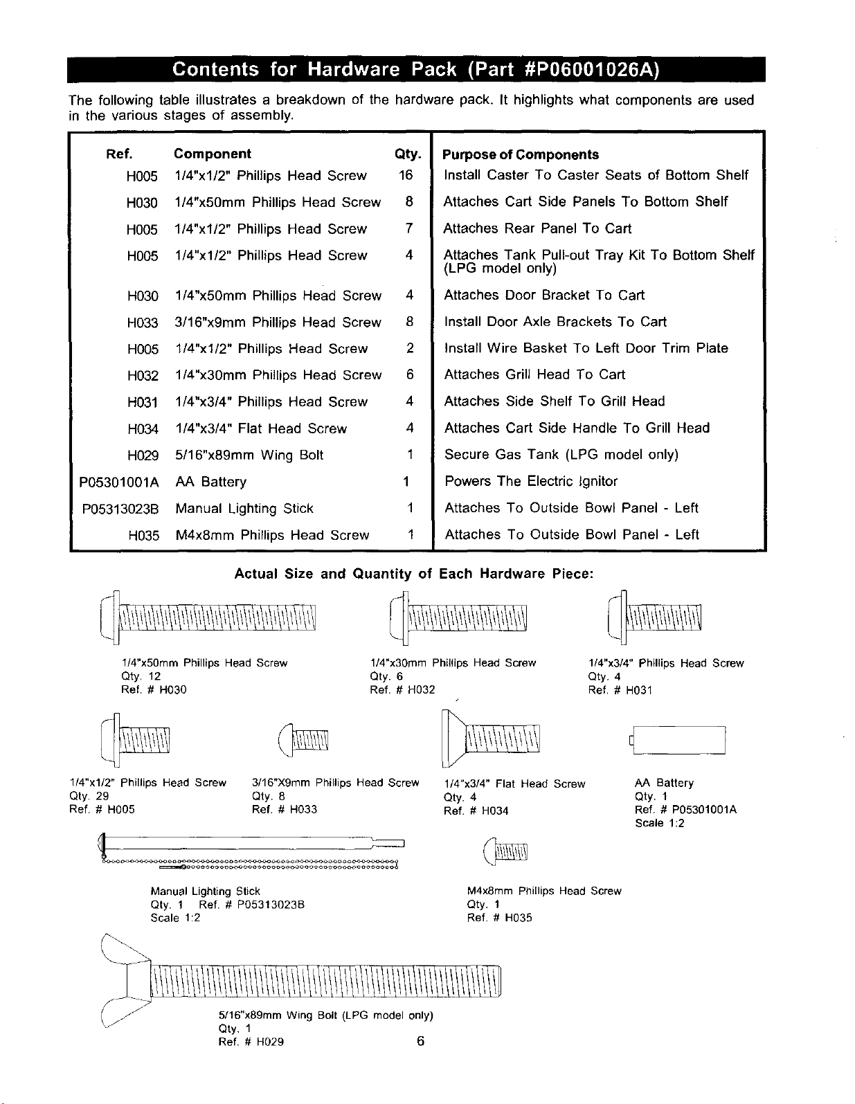
Thefollowingtableillustratesa breakdownofthe hardwarepack.It highlights what components are used
in the various stages of assembly.
Ref.
H005
H030
H005
H005
H030
H033
H005
H032
H031
H034
H029
P05301001A
P05313023B
H035
Component Qty.
1/4"x1/2" Phillips Head Screw 16
l/4"x50mm Phillips Head Screw 8
1/4"x1/2" Phillips Head Screw 7
1/4"x1/2" Phillips Head Screw 4
l/4"x50mm Phillips Head Screw 4
3/16"x9mm Phillips Head Screw 8
1/4"x1/2" Phillips Head Screw 2
l/4"x30mm Phillips Head Screw 6
1/4"x3/4" Phillips Head Screw 4
1/4"x3/4" Flat Head Screw 4
5/16"x89mm Wing Bolt 1
AA Battery 1
Manual Lighting Stick 1
M4x8mm Phillips Head Screw 1
Purpose of Components
Install Caster To Caster Seats of Bottom Shelf
Attaches Cart Side Panels To Bottom Shelf
Attaches Rear Panel To Cart
Attaches Tank Pull-out Tray Kit To Bottom Shelf
(LPG model only)
Attaches Door Bracket To Cart
Install Door Axle Brackets To Cart
Install Wire Basket To Left Door Trim Plate
Attaches Grill Head To Cart
Attaches Side Shelf To Grill Head
Attaches Cart Side Handle To Grill Head
Secure Gas Tank (LPG model only)
Powers The Electric Ignitor
Attaches To Outside Bowl Panel - Left
Attaches To Outside Bowl Panel - Left
l/4"x50mm Phillips Head Screw
Qty. 12
Ref. # H030
1/4"xl/2" Phillips Head Screw
Qty. 29
Ref. # H005
Manual Lighting Stick
Qty. 1 Ref. # P05313023B
Scale 1:2
Actual Size and Quantity of Each Hardware Piece:
1/4"x3Omm Phillips Head Screw
Qty. 6
Ref. # H032
3/16"X9mm Phillips Head Screw
Qty. 8
Ref. # H033
1/4"x3/4" Flat Head Screw
Qty. 4
Ref. # H034
M4x8mm Plliilips Head Screw
Qty. 1
Ref. # H035
1/4"x3/4" Phillips Head Screw
Qty. 4
Ref. # H031
AA Battery
Qty, 1
Ref. # P05301001A
Scale 1:2
5/16"x89mm Wing Bolt (LPG model only)
Qty. 1
Ref. # H029 6

LPG=LiquidPropane Gas
NG = Natural Gas
39
\34
j(LPG anly)44a
32
33
40
NG only)44b x
(LPG only)
38
59
(LPGonly)
5O
(LPG
It II \_°
43 670(LPG only)
_:_'67b(NG only)
\
51
49
53
7
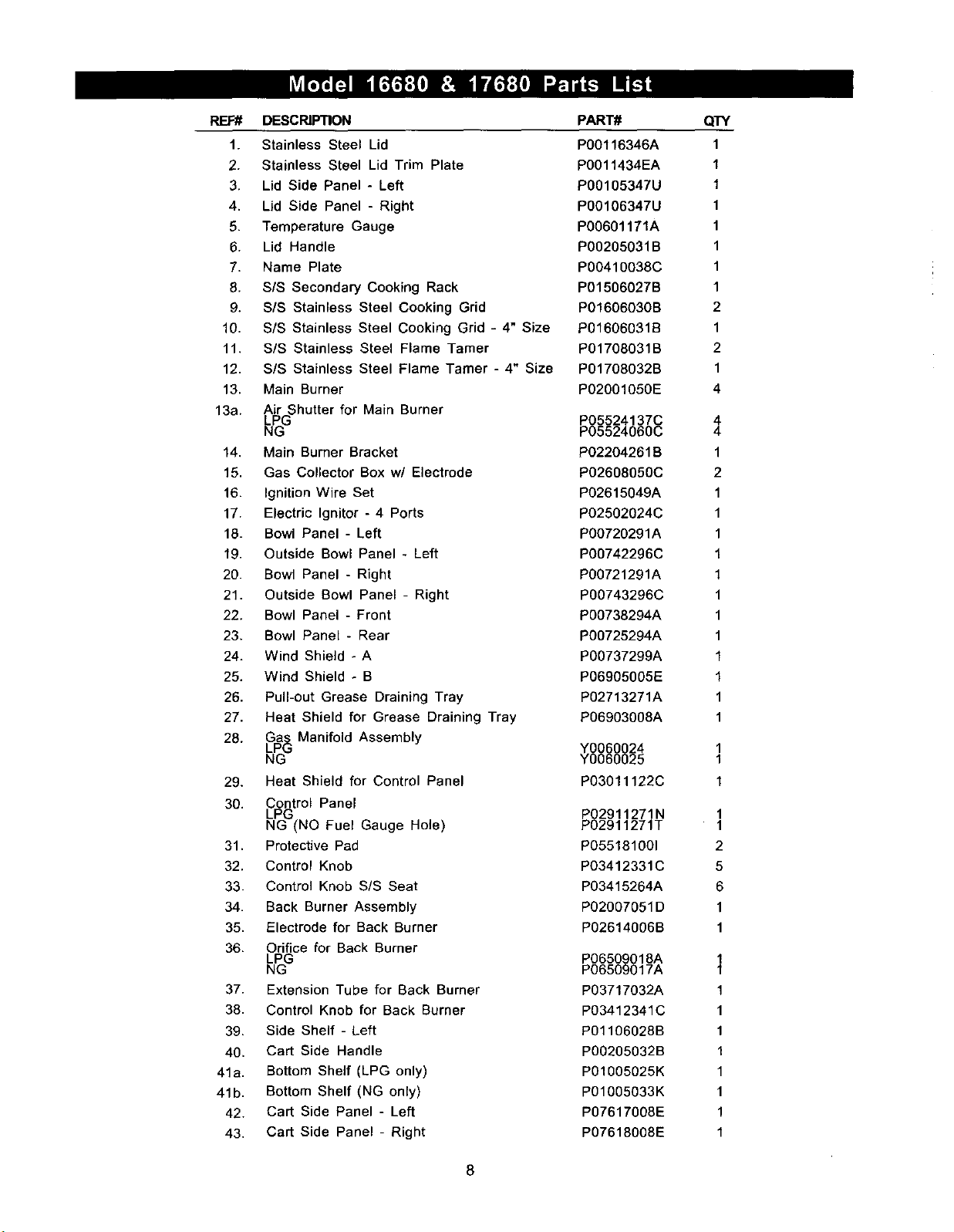
REF# DESCRIPTION
1. Stainless Steel Lid
2. Stainless Steel Lid Trim Plate
3. Lid Side Panel - Left
4. Lid Side Panel - Right
5. Temperature Gauge
6. Lid Handle
7. Name Plate
8. SIS Secondary Cooking Rack
9. SIS Stainless Steel Cooking Grid
10. S/S Stainless Steel Cooking Grid - 4" Size
11. SIS Stainless Steel Flame Tamer
12. S/S Stainless Steel Flame Tamer - 4" Size
13. Main Burner
13a. Air Shutter for Main Burner
41a. Bottom Shelf (LPG only)
41b. Bottom Shelf (NG only)
LPG
NG
14. Main Burner Bracket
15. Gas Collector Box w/ Electrode
16. Ignition Wire Set
17. Electric Ignitor - 4 Ports
18. Bowl Panel - Left
19. Outside Bowl Panel - Left
20. Bowl Panel - Right
21. Outside Bowl Panel - Right
22. Bowl Panel - Front
23. Bowl Panel - Rear
24. Wind Shield - A
25. Wind Shield - B
26. Pull-out Grease Draining Tray
27. Heat Shield for Grease Draining Tray
Ga Manifold Assembly
28. LP_
NG
29. Heat Shield for Control Panel
30. Control Panel
LPG
NG (NO Fuel Gauge Hole)
31. Protective Pad
32. Control Knob
33. Control Knob SIS Seat
34. Back Burner Assembly
35. Electrode for Back Burner
36. Orifice for Back Burner
LPG
NG
37. Extension Tube for Back Burner
38. Control Knob for Back Burner
39. Side Shelf - Left
40. Cart Side Handle
42. Cart Side Panel - Left
43. Cart Side Panel - Right
PART#
PO0116346A
P0011434EA
P00105347U
PO0106347U
P00601171A
P00205031B
P00410038C
PO1506027B
P01606030B
P01606031B
P01708031B
P01708032B
P02001050E
P05524137C
P05524060C
P02204261B
P02608050C
P02615049A
P02502024C
P00720291A
P00742296C
P00721291A
P00743296C
P00738294A
P00725294A
P00737299A
P06905005E
P02713271A
P06903008A
_0060024
0060025
P03011122C
_02911271N
02911271T
P055181001
P03412331C
P03415264A
PO2007051D
P02614006B
P06509018A
PO6509017A
P03717032A
P03412341C
P01106028B
P00205032B
P01005025K
P01005033K
P07617008E
P07618008E
QTY
1
1
1
1
1
1
1
1
2
1
2
1
4
4
4
1
2
1
1
1
1
1
1
1
1
1
1
1
1
1
1
1
1
1
2
5
6
1
1
1
1
1
1
1
1
1
1
1
1
8
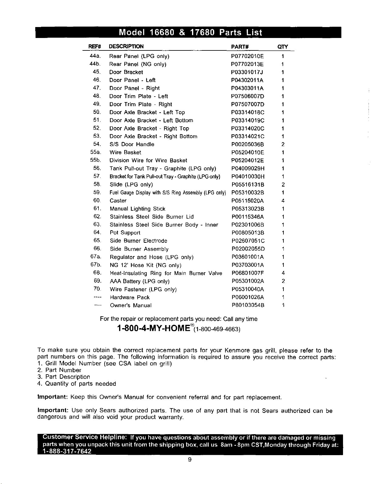
REF# DESCRIPTION PART# QTY
44a. Rear Panel (LPG only) P07702010E 1
44b. Rear Panel (NG only) P07702013E 1
45. Door Bracket P03301017J 1
46. Door Panel - Left P04302011A 1
47. Door Panel - Right P04303011A 1
48. Door Trim Plate - Left P07506007D 1
49. Door Trim Plate - Right P07507007D 1
50. Door Axle Bracket - Left Top P03314018C 1
51. Door Axle Bracket - Left Bottom P03314019C 1
52. Door Axle Bracket - Right Top P03314020C 1
53. Door Axle Bracket - Right Bottom P03314021C 1
54. S/S Door Handle P00205036B 2
55a. Wire Basket P05204010E 1
55b. Division Wire for Wire Basket P05204012E 1
56. Tank Pull-out Tray - Graphite (LPG only) P04O09029H 1
57. BracketforTank Pull-outTray - Graphite (LPGonly) P04010030 H 1
58. Slide (LPG only) P05516131B 2
59. Fuel GaugeDisplay withSIS Ring Assembly(LPG only) P05310032B 1
60. Caster P05115020A 4
61. Manual Lighting Stick P05313023B 1
62. Stainless Steel Side Burner Lid P00115346A 1
63. Stainless Steel Side Burner Body - Inner P02301006B 1
64. Pot Support PO0805013B 1
65. Side Burner Electrode P02607051C 1
66. Side Burner Assembly P02002055D 1
67a. Regulator and Hose (LPG only) P03601001A 1
67b. NG 12' Hose Kit (NG only) P03703001A 1
68. Heat-Insulating Ring for Main Burner Valve PO6801007F 4
69. AAA Battery (LPG only) P05301002A 2
70. Wire Fastener (LPG only) P05310040A 1
.... Hardware Pack P06001026A 1
.... Owner's Manual P80103054B 1
For the repair or replacement parts you need: Call any time
1-800-4-MY-HeM E (1-800-46g-4663)
To make sure you obtain the correct replacement parts for your Kenmore gas grill, please refer to the
part numbers on this page. The following information is required to assure you receive the correct parts:
1. Grill Model Number (see CSA label on grill)
2. Part Number
3. Part Description
4. Quantity of parts needed
Important: Keep this Owner's Manual for convenient referral and for part replacement.
Important: Use only Sears authorized parts. The use of any part that is not Sears authorized can be
dangerous and will also void your product warranty.
9
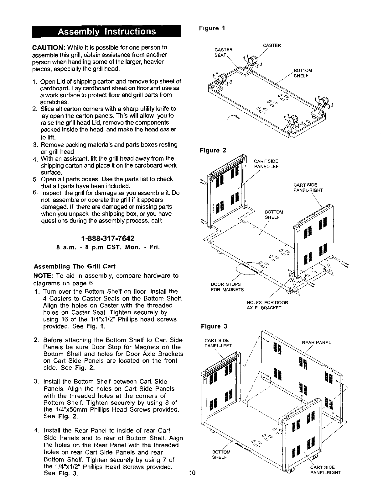
Figure 1
CAUTION: While it is possible for one person to
assemble this grill, obtain assistance from another
person when handling some of the larger, heavier
pieces, especially the grill head.
1. Open Lid of shipping carton and remove top sheet of
cardboard. Lay cardboard sheet on floor and use as
a work surface to protect floor and grill parts from
scratches.
2. Slice all carton corners with a sharp utility knife to
lay open the carton panels. This will allow you to
raise the grill head Lid, remove the components
packed inside the head, and make the head easier
to lift.
3. Remove packing materials and parts boxes resting
on grill head
4. With an assistant, lift the grill head away from the
shipping carton and place it on the cardboard work
surface.
5. Open all parts boxes. Use the parts list to check
that all parts have been included.
6. Inspect the grill for damage as you assemble it. Do
not assemble or operate the grill if it appears
damaged. If there are damaged or missing parts
when you unpack the shipping box, or you have
questions during the assembly process, call:
CASTER
Figure 2
CASTER
/
BOTTOM
/SHELF
/
CART SIDE
PANEL-LEFT
CART SIDE
PANEL-RIGHT
\
SOTi-OM
SHELF
1-888-317-7642
8 a.m. - 8 p.m CST, Mon. - Fri.
Assembling The Grill Cart
NOTE: To aid in assembly, compare hardware to
diagrams on page 6
1. Turn over the Bottom Shelf on floor. Install the
4 Casters to Caster Seats on the Bottom Shelf.
Align the holes on Caster with the threaded
holes on Caster Seat. Tighten securely by
using 16 of the 1/4"xl/2" Phillips head screws
provided. See Fig. 1.
2. Before attaching the Bottom Shelf to Cart Side
Panels be sure Door Stop for Magnets on the
Bottom Shelf and holes for Door Axle Brackets
on Cart Side Panels are located on the front
side. See Fig. 2.
3. Install the Bottom Shelf between Cart Side
Panels. Align the holes on Cart Side Panels
with the threaded holes at the corners of
Bottom Shelf. Tighten securely by using 8 of
the 1/4"x50mm Phillips Head Screws provided.
See Fig. 2.
DOOR STOPS
FOR MAGNETS
Figure 3
CART SIDE
PANEL-LEFT
\
\
HOLES FOR DOOR
/
AXLE BRACKET
REAR PANEL
!
4. Install the Rear Panel to inside of rear Cart
Side Panels and to rear of Bottom Shelf. Align
the holes on the Rear Panel with the threaded
holes on rear Cart Side Panels and rear BOTTOM
Bottom Shelf. Tighten securely by using 7 of SHELF
the 1/4"xl/2" Phillips Head Screws provided.
See Fig. 3. 10
CART SlOE
PANEL-RIGHT
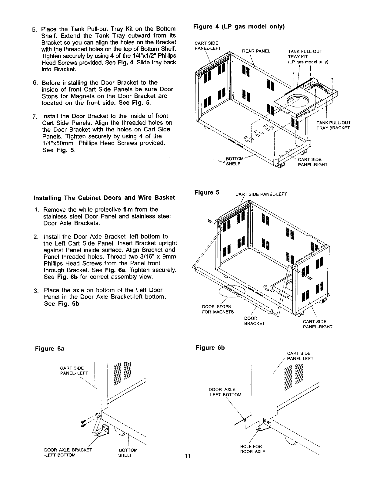
5. Place the Tank Pull-out Tray Kit on the Bottom
Shelf. Extend the Tank Tray outward from its
Bracket so you can align the holes on the Bracket
with the threaded holes on the top of Bottom Shelf.
Tighten securely by using 4 of the 114"x112"Phillips
Head Screws provided. See Fig. 4. Slide tray back
into Bracket.
6. Before installing the Door Bracket to the
inside of front Cart Side Panels be sure Door
Stops for Magnets on the Door Bracket are
located on the front side. See Fig. 5.
7. Install the Door Bracket to the inside of front
Cart Side Panels• Align the threaded holes on
the Door Bracket with the holes on Cart Side
Panels• Tighten securely by using 4 of the
l/4"x50mm Phillips Head Screws provided.
See Fig. 5.
Figure 4 (LP gas model only)
CART SIDE
PANEL-LEFT
REAR PANEL
TANK PULL-OUT
TRAY KIT
(LP gas model only)
t
I
!
i
TANK PULL-OUT
TRAY BRACKET
CART SIDE
PANEL*RIGHT
Installing The Cabinet Doors and Wire Basket
1, Remove the white protective film from the
stainless steel Door Panel and stainless steel
Door Axle Brackets•
2, Install the Door Axle Bracket--left bottom to
the Left Cart Side Panel. Insert Bracket upright
against Panel inside surface. Align Bracket and
Panel threaded holes• Thread two 3/16" x 9mm
Phillips Head Screws from the Panel front
through Bracket• See Fig. 6a. Tighten securely.
See Fig. 6b for correct assembly view.
3. Place the axle on bottom of the Left Door
Panel in the Door Axle Bracket-left bottom.
See Fig. 6b.
Figure 6a
CART SIDE
PANEL- LEFT
Figure 5
DOOR STOPS
FOR MAGNETS
Figure 6b
CART SIDE PANEL-LEFT
DOOR
BRACKET
CART SIDE
PANEL-RIGHT
CART SIDE
PANEL-LEFT
I
DOOR AXLE
-LEFT BOTTOM
\
\
DOOR AXLE BRACKET BOTTOM DOOR AXLE
-LEFT BOTTOM SHELF 11
HOLE FOR

4. Before installing the Door Axle Bracket-left top
to the Left Cart Side Panel, with an assistant,
hold the Door Panel and keep it vertical.
5. Place the axle on top of the Left Door Panel
in the Door Axle Bracket-left top. Install the
Door Axle Bracket-left top to the Left Cart
Side Panel. Align the holes on the Door Axle
Bracket-left top with threaded holes on the top
of Left Cart Side Panel. Tighten securely by
using 2 of the 3/16"x9mm Phillips Head
Screws provided. See Fig. 6c.
Figure 6c
DOOR AXLE BRACKET PANEL- LEFT
-LEFT TOP
\ "
\
CART SIDE
6. Follow steps 1 to 5 of the Installing the Left
Cabinet Door Procedures to install Right
cabinet Doors.
7. Attach the Wire Basket to the Door Trim Plate
-Left as shown in Fig.6d. Tighten securely
using 2 of the 1/4"xl/2" Phillips Head screws
provided. Place the Division Wire on the Wire
Bracket.
Figure 6d
%" DIVISION
WIRE
DOOR TRIM
PLATE-LEFT WIRE BASKET
Installing The Grill Head
1. Now that you've assembled the grill cart you
can install the pre-assembled Grill Head. See
Fig. 7. If you haven't already done so, open
the Grill Lid and remove the packed
components. Lock the casters. Even with the
components removed, the next step requires 2
people.
2,
With an assistants, carefully lift and position
the Grill Head onto the grill cart. Align the 6
holes of the Bowl Side Panel to the threaded
holes on the Cart Side Panel Bracket. Secure
firmly by using 6 of the 1/4"x30mm Phillips
Head Screws provided. BE CAREFUL NOT TO
PINCH FINGERS WHEN LOWERING HEAD
ONTO CART
3.
Open the front Doors of cabinet. Remove fasten-
ing band from Fuel Gauge Display Wire Plug "A"
that is behind the Heat Shield of the Control
Panel.
4.
Place the Wire Plug "A" through the slot in side
of Right Cart Side Panel as shown in Fig. 8.
HOLE FOR
DOOR AXLE
DOOR AXLE
-LEFT TOP
Figure 7
CART SIDE "_
PANEL "_.
BRACKET _'_
Figure 8 (LP gas model only)
CONTROL PANEL
SLOT FOR WIRE
PLUG "A"
12
BOWL SIDE
PANEL
PRE-ASSEMBLED
REGULATOR
(LP gas model only)
PANEL-RIGHT
FUEL GAUGE DISPLAY
( LP gas model only)
 Loading...