

Page 1

Use & Care Guide
Model: D02 M90349
Kenmore
®/MD
Natural Gas Grill
P/N G651-001-250801
Sears Canada Inc.
Toronto, ON., M5B 2C3
www.sears.ca
/MC
™
Model 466226313 • Jan-11-13
Page 2
DANGER
WARNING
If you smell gas:
1. Shut off gas to the appliance.
2. Extinguish any open flame.
3. Open lid.
4. If odor continues, keep away from the appliance
and immediately call your gas supplier or your
fire department.
WARNING
1. Do not store or use gasoline or other
flammable liquids or vapors in the vicinity of
this or any other appliance.
2. An LP Tank shall not be stored in the vicinity
of this or any other appliance.
Call the Grill Information Center for Help and Parts
Missing Parts? Assembly Questions?
Before returning grill to store, call 1-800-241-7548
Product Record
IMPORTANT: Fill out the product record information below.
Model Number
Serial Number
See rating label on grill for serial number.
Operation Problems?
CALIFORNIA PROPOSITION 65
1. Combustion by-products produced when using this
product contain chemicals known to the State of
California to cause cancer, birth defects, and other
reproductive harm.
2. This product contains chemicals, including lead
and lead compounds, known to the State of
California to cause cancer, birth defects or other
reproductive harm.
Wash your hands after handling this product.
Installation Safety Precautions
• Use grill, as purchased, only with natural gas and the hose
supplied.
• Grill installation must conform with local codes, or in the
absence of local codes, with either the National Fuel Gas
Code, ANSI Z223.1/ NFPA 54, Natural Gas and Propane
Installation Code, CSA B149.1, or Propane Storage and
Handling Code, B149.2, or the Standard for Recreational
Vehicles, ANSI A 119.2/NFPA 1192, and CSA Z240 RV Series,
Recreational Vehicle Code, as applicable.
• All electrical accessories (such as a rotisserie) must be
electrically grounded in accordance with local codes, or
National Electrical Code, ANSI / NFPA 70 or Canadian
Electrical Code, CSA C22.1. Keep any electrical cords
and/or fuel supply hoses away from any hot surfaces.
• Grill is not for use in or on recreational vehicles and/or
boats.
• This grill is safety certified for use in the United States
and/or Canada only. Do not modify for use in any other
location. Modification will result in a safety hazard.
• The hose assembly supplied must be used and replacements
must be those specified by appliance manufacturer.
Safety Symbols
The symbols and boxes shown below explain what each
heading means. Read and follow all of the messages found
throughout the manual.
Date Purchased
To Installer/Assembler: Leave these instructions with
consumer.
To Consumer: Keep this manual for future reference.
CAUTION
Some parts may contain sharp edges, especially
as noted in these instructions.
Wear protective gloves if necessary.
CAUTION
For residential use only. Do not use for commercial
cooking.
© 2013 Sears Canada Inc.
2 • 466226313
DANGER
DANGER: Indicates an imminently hazardous situation
which, if not avoided, will result in death or serious injury.
WARNING
WARNING: Be alert to the possibility of serious bodily
injury if the instructions are not followed. Be sure to read
and carefully follow all of the messages.
CAUTION
CAUTION: Indicates a potentially hazardous situation which,
if not avoided, may result in minor or moderate injury.
Printed in China
Page 3
Table of Contents
For Your Safety . . . . . . . . . . . . . . . . . . . . . . . . . . . . . . . . . . . . . . 2
Grill Information Center . . . . . . . . . . . . . . . . . . . . . . . . . . . . . . 2
WARRANTY
KENMORE GRILL WARRANTY
Product Record Information . . . . . . . . . . . . . . . . . . . . . . . . . . . 2
Safety Symbols. . . . . . . . . . . . . . . . . . . . . . . . . . . . . . . . . . . . . . 2
Installation Safety Precautions . . . . . . . . . . . . . . . . . . . . . . . 2-4
Kenmore Grill Warranty . . . . . . . . . . . . . . . . . . . . . . . . . . . . . . 3
Grilling Guide . . . . . . . . . . . . . . . . . . . . . . . . . . . . . . . . . . . . . 5-8
Use and Care. . . . . . . . . . . . . . . . . . . . . . . . . . . . . . . . . . . . . 9-14
Parts List . . . . . . . . . . . . . . . . . . . . . . . . . . . . . . . . . . . . . . . . . . . 15
Parts Diagram . . . . . . . . . . . . . . . . . . . . . . . . . . . . . . . . . . . . . . 16
Assembly . . . . . . . . . . . . . . . . . . . . . . . . . . . . . . . . . . . . . . . 17-29
Troubleshooting . . . . . . . . . . . . . . . . . . . . . . . . . . . . . . . . . 30-32
WARNING
• Read and follow all Safety, Assembly,
and Use and Care Instructions in this
Guide before assembling and cooking
with this grill.
• Failure to follow all instructions in this
Use and Care Guide may lead to fire or
explosion, which could result in property
damage, personal injury or death.
One Year Full Warranty on Kenmore Grill
If this grill fails due to a defect in material or workmanship
within one year from the date of purchase, call 1-800-241-
7548 to arrange for free repair parts (or replacement if repair
proves impossible).
Ten-Year Limited Warranty on Burners
For ten year from the date of purchase, any burner that
rusts through will be replaced free of charge.
All warranty coverage excludes ignitor batteries and grill part
paint loss, discoloration or surface rusting, which are either
expendable parts that can wear out from normal use within
the warranty period, or are conditions that can be the result
of normal use, accident or improper maintenance.
All warranty coverage is void if this grill is ever used for
commercial or rental purposes.
All warranty coverage applies only if this grill is used in
Canada.
Sears Canada Inc.
Toronto, ON., M5B 2C3
This Grill is for Outdoor Use Only
Tools needed for assembly:
Adjustable wrench (not provided)
Screwdriver (not provided)
7/16" Combination wrench (not provided)
466226313 • 3
Page 4

WARNING
CAUTION
Do not attempt to repair or alter the hose/quick
disconnect for any “assumed” defect. Any
modification to this assembly will void your
warranty and create the risk of a gas leak and fire.
Use only authorized replacement parts supplied by
manufacturer.
NOTE: DO NOT over tighten screws and washers that
come into contact with porcelain coated surfaces.
Over tightening may cause the porcelain coating to
crack and break, resulting in exposed metal that will
be prone to rust.
Natural Gas Connections and Service Regulators
Above 1/2 psi.
Prior to 1998, all residential gas service regulators were
set with an outlet pressure of 7 inches water column.
In the 1998 edition of NFPA 54, the National Fuel Gas
Code, a change was made allowing service regulators
of 2 and 5 psi.
With this change it was also required that an in line
regulator be connected between the service regulator
and the appliance regulator if the 2 or 5 psi system is
used. This additional regulator is not supplied with the
product.
It is possible for a consumer, making the connection
themselves, or a plumber, not checking, to tap into a 2
or 5 psi line. If a pressure of 2 psi or greater is supplied
to the appliance regulator on certain grills it will shut
down and not deliver any gas to the grill. Other
concerns are the quick disconnect socket and hose
which are only rated to 1/2 psi.
If the quick disconnect socket, hose, and grill are
properly connected and still not getting gas, delivery
pressure needs to be verified. If pressure is greater than
1/2 psi, make sure that an in line regulator is present.
Once the grill has been over-pressured, the regulator
may or may not have been damaged. The best
practice is to replace the regulator.
Using pots larger than 6 quarts in capacity could
exceed weight limit of the
side burner shelf
or side shelf,
resulting in failure
of grill cart
components.
4 • 466226313
Page 5

GRILLING GUIDE – Getting Started
First Time Use
Read your Assembly Manual and ensure the grill is put
together properly. Remove all Point-of-Purchase advertising
material from all grill surfaces before first use. We
recommend operating your grill on its highest setting for 1520 minutes prior to your first use. This aids in removing the
oils used during manufacturing.
Lava Rock / Briquettes
This gas grill has been designed, engineered, and tested to
be used with flame tamers or heat distribution plates to
provide more even heating, improve the cleaning process,
and reduce flare-ups. The addition of after market lava
rocks, charcoal, or briquettes of any type will cause poor
combustion and increase the likelihood of a grease fire, and
is not recommended. Using briquettes, lava rock, or
charcoal in this grill will void your warranty. For extra
smoke flavor, we recommend using a smoker box with wood
chips.
Temperature - Convective Grills ONLY.
The temperature gauge in the hood of your new grill
measures air temperature. The air temperature inside your
grill will never be as hot as the temperature at the cooking
surface.
Pre-Heating Your Grill
Just like your home oven, your grill should be pre-heated to
provide optimum performance. Pre-heat the grill on high for
10-15 minutes – longer if weather conditions require. Please
refer to the lighting instructions inside the Product Guide if
you have questions about how to light your grill. A matchlight chain and hole is provided for your convenience.
466226313 • 5
Page 6

GRILLING GUIDE – Grilling 101
Outdoor grilling is really quite simple. You'll succeed with
burgers, dogs, or steaks usually on your very first try. With
experience, you will learn how to work with your grill,
creating more imaginative meals all the time. This
knowledge makes up the art of grilling. Before you start
grilling, organize your food according to cooking technique
and required cooking time, and optimize the use of your
grilling area.
Direct Cooking
Direct cooking involves grilling your meat directly over high
heat. It is perfect for searing steaks, chops, and other
smaller pieces of meat and vegetables that quickly make
their way to the table.
Rotisserie Cooking
Rotisserie cooking is best for 'round' meat, such as large
roasts, whole poultry, and pork. It generally requires an
accessory motor and spit rod that allows the meat to be
turned at a constant speed. Rotisserie cooking is best done
in front of a special rotisserie burner, or utilizing an indirect
cooking burner arrangement. A pan can be placed
underneath the meat to catch grease and food drippings,
and helps minimize clean-up.
Indirect Cooking
Indirect cooking utilizes select burners to circulate heat
throughout the grill, without direct contact between the
meat and the flame. The meat is placed over the burner
that is 'off'. This method is generally used to slow cook
large cuts of meat and poultry. A pan can be placed
underneath the meat to catch grease and food drippings,
and helps minimize clean-up.
Food Safety
Food safety is a very important part of enjoying the
outdoor cooking experience. To keep food safe from
harmful bacteria, follow these four basic steps:
Clean: Wash hands, utensils, and surfaces with hot soapy
water before and after handling raw meat.
Separate: Separate raw meats from ready-to-eat foods to
avoid cross contamination. Use a clean platter and utensils
when removing cooked foods.
Cook: Cook meat and poultry thoroughly to kill bacteria.
Use a thermometer to ensure proper internal food
temperatures.
Chill: Refrigerate prepared foods and leftovers promptly.
6 • 466226313
Page 7
GRILLING GUIDE – Tips & Tricks
Food Temperature
Beef, ve al an d lamb (pieces and whole cuts) -
medium-rare 63°C (145°F)
Beef, ve al an d lamb (pieces and whole cuts) medium 71°C (160°F)
Beef, ve al an d lamb (pieces and whole cuts) well done 77°C (170°F
Po rk (pieces and whole cuts) 71°C (160°F)
Po u l try (e.g. chicken, turkey, duck) - pieces 74°C (165°F)
Po u l try - whole 85°C (185°F)
Ground meat an d me at mixtures (e.g.
burgers, sausages, meatballs, meatloaf,
casseroles)- beef, veal, lamb and pork 71°C (160°F)
Ground meat an d me at mixtures - poultry 74°C (165°F)
Egg di s he s 74°C (165°F)
Othe rs (hot dogs, stuffing and leftovers) 74°C (165°F)
Cooking on your new grill is a hands-on experience, and it
is recommended to remain outside with your grill while
cooking. Grilling can be affected by many external
conditions. In cold weather, you will need more heat to
reach an ideal cooking temperature, and grilling may take
longer. The meat's internal temperature and thickness can
also affect cooking times. Cold and thicker meats will take
longer to cook.
Internal Meat Temperatures
Meat cooked on a grill often browns very fast on the
outside. Therefore, use a meat thermometer to ensure it has
reached safe internal temperatures.
Canadian Food Inspection Agency
Recommended Internal cooking tempeaures
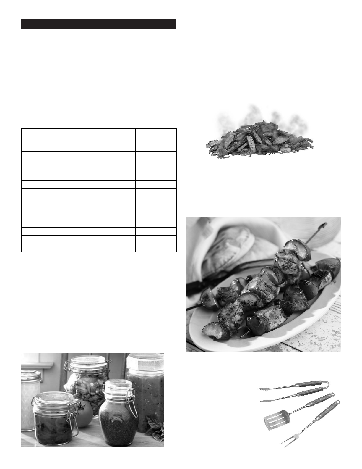
Wood Chips
For extra smoke flavor when grilling, try adding wood chips.
Soak the chips in water for approximately 30 minutes
before adding to a smoke box or pan. Place smoke box or
pan on top of the cooking grate above the flame. Turn grill
on high until the wood starts to smoke. Reduce heat to
desired temperature for cooking, and place food on
cooking grate as desired. Close lid to retain more smoke.
Hardwood varieties that work particularly well with grilled
foods include Alder, Apple, Cherry, Grapevines, Hickory,
Mesquite, Oak, Rosemary and Sassafras.
Skewers
Metal skewers should be flat, with long handles. Round
skewers allow food to roll when turned, so it may not cook
as evenly. Use metal skewers when cooking meat kabobs.
Wooden skewers should be soaked in water for an hour
before use, and are best used for quick cooking foods such
as vegetables and fruits.
For more information call : Canadian Food Inspection Agency
Hotline at 1-800-442-2342.
Sauces
Sauces containing sugars and fats can cause flare-ups, and
your food may burn. In general, apply these sauces during
the final 10 minutes of cooking. Keep in mind, use of
excessive sauces or glazes will also require extra cleaning
afterwards.
Marinades and Rubs
To enhance the flavor of grilled foods, a liquid marinade or
dry rub can be used prior to cooking. Meat can be either
soaked or injected with liquid marinade up to 24 hours
prior to grilling. Dry rubs can be applied directly to the
meat immediately before grilling.
Utensils
Use tongs or a spatula to handle the food instead of a fork,
and don't turn the food too
often. Piercing the food
with a fork will release
juices that you want in
the meat, and may
cause flare-ups.
466226313 • 7
Page 8
GRILLING GUIDE – Cleaning Your Grill
Why Clean?
We've all heard the saying, “an ounce of prevention is worth
a pound of cure.” This is great advice when it comes to
keeping your grill clean.
Routine Care
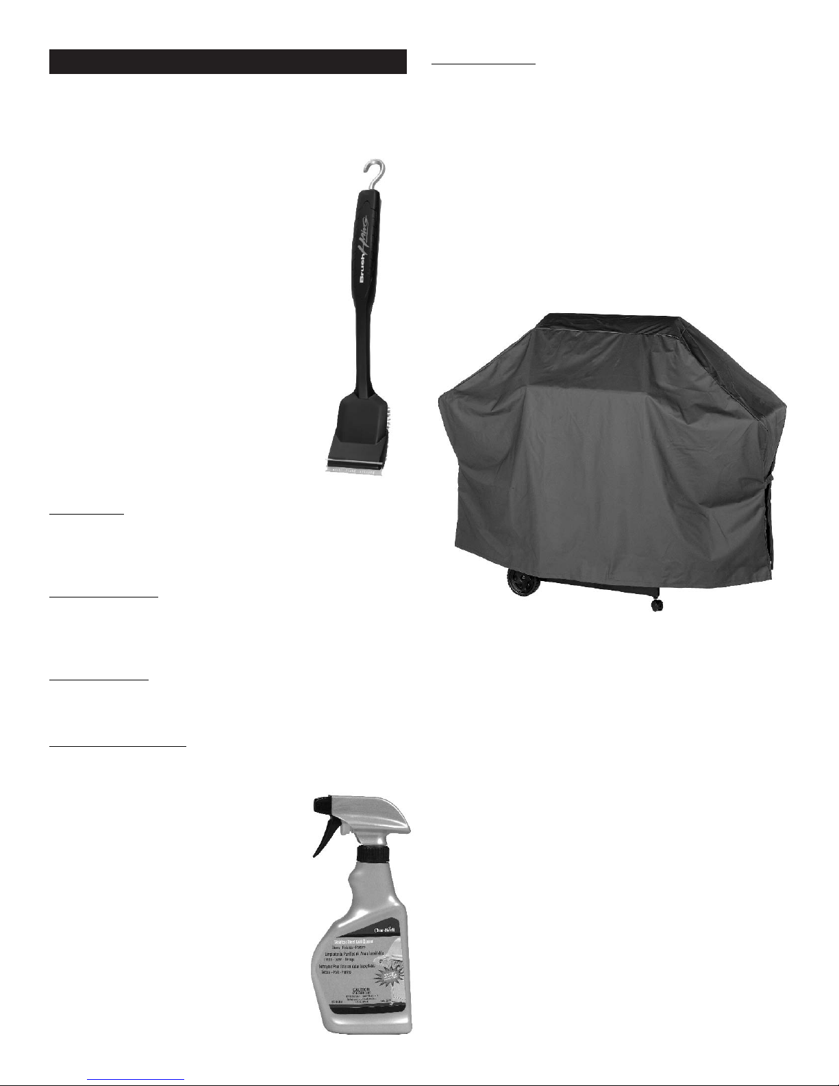
Periodic cleaning of this grill is necessary,
as grill fires can occur when grease and
food debris collect in the bottom of the grill.
After each use, remove any remaining
food particles from the cooking grate and
inside of the grill using a grill brush. Do
this after the grill has cooled down, yet is
still warm. It is much easier to clean food
particles while warmth is still present, than
after the food particles have completely
cooled and hardened. This grill is not
designed to be 'burned off' by closing the
lid and turning the burners on High for an
extended time. The excessive heat
generated can cause leftover grease to
catch fire, and can cause permanent
damage to your grill.
Cooking surfaces: If a bristle brush is used to clean any of
the grill cooking surfaces, ensure no loose bristles remain on
cooking surfaces prior to grilling. It is not recommended to
clean cooking surfaces while grill is hot.
Storing Your Grill
• Clean cooking grates.
• Store grill in dry location.
• Cover grill if stored outdoors. Choose from a variety of
grill covers offered by manufacturer.
• Store grill indoors ONLY if Natural Gas hose is
disconnected from quick disconnect socket.
• When removing grill from storage, follow the 'Cleaning the
Burner Assembly' instructions in the Use and Care section
of the Product Guide.
General Cleaning
Plastic parts: Wash with warm soapy water and wipe dry.
Do not use abrasive cleaners, degreasers or a concentrated
grill cleaner on plastic parts. Damage to and failure of
parts can result.
Porcelain surfaces: Because of glass-like composition, most
residue can be wiped away with baking soda/water
solution or glass cleaner. Use non-abrasive scouring powder
for stubborn stains.
Painted surfaces: Wash with mild detergent or non-abrasive
cleaner and warm water. Wipe dry with a soft non-abrasive
cloth.
Stainless steel surfaces: Stainless steel can rust under certain
conditions. This can be caused by environmental conditions
such as chlorine or salt water, or improper
cleaning tools such as wire or steel
wool. It can also discolor due to heat,
chemicals, or grease build-up. To
maintain your grill's high quality
appearance, wash with mild detergent
and warm water, or use a stainless
steel grill cleaner. Baked-on grease
deposits may require the use of an
abrasive plastic cleaning pad. Use only
in direction of brushed finish to avoid
damage. Do not use abrasive pad on
areas with graphics.
Critters
Spiders like to make their homes in the venturi tubes of
grills. These must be inspected and cleaned regularly to
ensure there are no blockages. Refer to the Use and Care
portion of this Product Guide for complete information.
8 • 466226313
Page 9
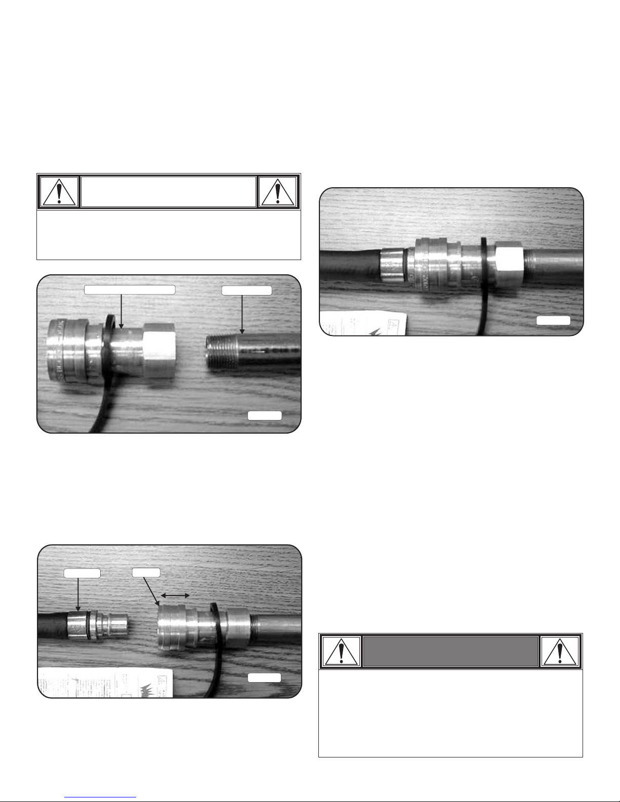
Connecting Your Grill to the Natural Gas Source.
1. A professionally-installed shut-off valve between the
supply piping and the socket is recommended, but
not required, by the National Fuel Gas Code. Socket
connection must be made outdoors.
2. Coat the gas supply pipe nipple with gas resistant
pipe dope or approved teflon tape. Screw socket
onto gas supply pipe (house gas source) as shown in
Figure A below, and wrench-tighten.
CAUTION
The quick disconnect socket should never be
connected to the grill. Direction of gas flow is
indicated on the socket.
Quick disconnect socket House piping
4. When the quick disconnect socket and the gas hose
are connected, a valve in the socket opens
automatically to permit full gas flow. When the gas
hose is disconnected, the valve in the socket instantly
and positively shuts off the flow of gas. Because the
valve in the socket positively shuts off the flow of
gas, the grill can be disconnected from the gas
source by disconnecting the gas hose from the quick
disconnect socket. The socket should be left attached
to the gas source (house piping). Figure C, below,
shows properly connected hose and socket.
Figure C
Figure A
3. Turn all grill valves to the off position. Pull back the
sleeve on the quick disconnect socket and insert the
unattached end of the gas hose into the socket.
Release the sleeve and continue pushing the hose
into the socket until the sleeve snaps into the locked
position. See Figure B.
Gas hose
Sleeve
With proper assembly, the gas hose cannot be
removed without pushing the quick disconnect sleeve
back. To disconnect, push sleeve back and pull plug
out of sleeve (this automatically shuts off gas).
Please Note: Hose and assembly are C.S.A. listed for
natural gas, manufactured gas, mixed gas and for
liquefied petroleum and for LP Gas-Air mixtures on
basis of 0.64 specific gravity for 1000 BTU’s per
cubic foot of gas at 0.3 in. water column pressure
drop. Only ANSI Z21.54 approved hoses should be
used with this grill.
The appliance and its individual shut off valve must
be disconnected from the gas supply piping system
during any pressure testing on that system at test
pressures in excess of 1/2 psig (3.5kPa).
The appliance must be isolated from the gas supply
piping system by closing its individual manual shutoff
valve during any pressure testing of the gas supply
piping system at test pressures equal to or less than
1/2 psi (3.5kPa).
Figure B
WARNING
Do not use hard metal piping of any kind to
connect this type of grill to natural gas source. Use
only hose specified by manufacturer. Using hard
metal piping or convoluted metal tubing is an
unsafe practice. Movement of the grill can cause
breakage of metal pipe.
466226313 • 9
Page 10

USE AND CARE
Leak Testing
1. Turn all grill control knobs to OFF.
DANGER
• NEVER store a spare LP cylinder under or near
the appliance or in an enclosed area.
2. Be sure gas hose is tightly connected to gas
source.
3. Completely open gas source. If you hear a rushing
sound, turn gas off immediately. There is a major
leak at the connection. Correct before proceeding.
4. Brush soapy solution onto area circled below.
WARNING
• Outdoor gas appliance is not intended to be
installed in or on a boat.
• Outdoor gas appliance is not intended to be
installed in or on an RV.
• Never attempt to attach this grill to the self-contained
LP gas system of a camper trailer or motor home.
• Do not use grill until leak-tested.
• If a leak is detected at any time, STOP and call the
fire department.
• If you cannot stop a gas leak, immediately close
gas valve and call your fire department!
NOTE: Your grill
NOTE: Side burner
shelf fascia not
shown for clarity.
5. If “growing” bubbles appear, there is a leak. Close
gas source immediately and tighten connection. If
leaks cannot be stopped do not try to repair.
6. Always close gas source after performing leak test.
Safety Tips
• When grill is not in use, turn off all control knobs
and gas source.
may NOT be
equipped with a
sideburner.
10 • 466226313
Page 11

WARNING
For Safe Use of Your Grill and to Avoid Serious
Injury:
• Do not let children operate or play near grill.
• Keep grill area clear and free from materials that
burn.
• Do not block holes in sides or back of grill.
• Check burner flames regularly.
• Use grill only in well-ventilated space. NEVER use
in enclosed space such as carport, garage, porch,
covered patio, or under an overhead structure of
any kind.
• Do not use charcoal or ceramic briquets in a gas
grill.
• Do not cover grates with aluminum foil or any
other material. This will block burner ventilation
and create a potentially dangerous condition
resulting in property damage and/or personal
injury.
• Use grill at least 3 ft. from any wall or surface.
Maintain 10 ft. clearance to objects that can catch
fire or sources of ignition such as pilot lights on
water heaters, live electrical appliances, etc.
Safety Tips
▲ When grill is not in use, turn off all control knobs
and remove gas hose from quick disconnect socket.
▲ Never move grill while in operation or still hot.
▲ Use long-handled barbecue utensils and oven mitts
to avoid burns and splatters.
▲ Maximum load for side burner and side shelf is 10
lbs.
▲ The grease tray or cup must be installed during use
and emptied after each use. Do not remove grease
tray or cup until grill has completely cooled.
▲ Clean grill often, preferably after each cookout. If a
bristle brush is used to clean any of the grill cooking
surfaces, ensure no loose bristles remain on cooking
surfaces prior to grilling. It is not recommended to
clean cooking surfaces while grill is hot.
▲ If you notice grease or other hot material dripping
from grill onto valve or gas hose, turn off gas supply
at once. Determine the cause, correct it, then clean
and inspect valve and hose before continuing.
Perform a leak test.
▲ Keep ventilation openings in cylinder enclosure (grill
cart) free and clear of debris.
▲ Do not store objects or materials inside the grill cart
enclosure that would block the flow of combustion
air to the underside of either the control panel or
the firebox bowl.
▲ If you have a grill problem see the "Troubleshooting
Section".
• Apartment Dwellers:
Check with management to learn the requirements
and fire codes for using a gas grill in your
apartment complex. If allowed, use outside on the
ground floor with a three (3) foot clearance from
walls or rails. Do not use on or under balconies.
• NEVER attempt to light burner with lid closed. A
buildup of non-ignited gas inside a closed grill is
hazardous.
CAUTION
• Putting out grease fires by closing the lid is not
possible. Grills are well ventilated for safety
reasons.
• Do not use water on a grease fire. Personal injury
may result. If a grease fire develops, turn knobs
to off position and remove hose from quick
disconnect socket.
• Do not leave grill unattended while preheating or
burning off food residue on HIGH. If grill has not
been regularly cleaned, a grease fire can occur
that may damage the product. Follow instructions
on General Grill Cleaning and Cleaning The
Burner Assembly to prevent grease fires.
466226313 • 11
Page 12
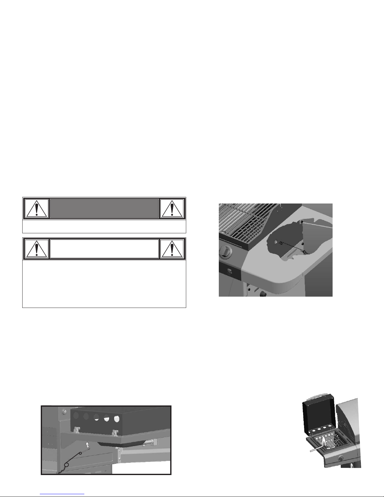
Ignitor Lighting
▲ Do not lean over grill while lighting.
1. Turn OFF gas burner control valves.
2. Turn ON gas at source.
3. Open lid during lighting.
4. To ignite, push and turn IGNITION BURNER knob
to HIGH.
5. Push and hold ELECTRONIC IGNITION button until
the burner lights.
6. If ignition does NOT occur in 5 seconds, turn the
burner controls OFF, wait 5 minutes and repeat the
lighting procedure.
7. To ignite remaining burners, turn knob to the HIGH
position starting with the burners closest to
IGNITION BURNER first. If ignitor does not work,
follow match lighting instructions.
8. For grills equipped with ELECTRONIC IGNITION
at each burner:
Repeat steps 4 through 6 to light each burner.
9. Once each burner has ignited, turn knobs to
desired setting.
SEAR Burner Ignitor Lighting
▲ Do not lean over grill while lighting.
1. Turn OFF gas burner control valves.
2. Turn ON gas at source.
3. Open lid during lighting.
4. To ignite, push and turn SEAR burner knob to HIGH.
5. Push and hold ELECTRONIC IGNITION button until
the burner lights.
6. If ignition does NOT occur in 5 seconds, turn the
burner controls OFF, wait 5 minutes and repeat the
lighting procedure.
SEAR Burner Match-Lighting
▲ Do not lean over grill while lighting.
1. Open lid. Turn ON gas at source.
2. Place match into match holder (hanging from right
side panel of grill). Light match; then light burner
by placing match through the match light hole on
right side of grill.
3. Push in and turn SEAR burner knob to the HIGH
position. Be sure burner lights and stays lit.
WARNING
Turn controls and gas source OFF when not in use.
CAUTION
If ignition does NOT occur in 5 seconds, turn the
burner controls OFF, wait 5 minutes and repeat the
lighting procedure. If the burner does not ignite with
the valve open, gas will continue to flow out of the
burner and could accidently ignite with risk of injury.
Match-Lighting
▲ Do not lean over grill while lighting.
1. Open lid. Turn ON gas at source.
2. Place match into match holder (hanging from left
side panel of grill). Light match; then light burner
by placing match through the match light hole on
left side of grill.
3. Push in and turn far left burner knob to the HIGH
position. Be sure burner lights and stays lit.
4. Light adjacent burners in sequence by pushing
knobs in and turning to the HIGH position.
NOTE: Your grill may NOT be equipped with a Side
burner!
Side burner Ignitor Lighting
▲ Do not lean over grill while lighting.
1. Open side burner lid. Turn ON gas at source.
2. Turn side burner knob to the HIGH position, push
and hold ELECTRONIC IGNITOR button.
3. If side burner does NOT light within 5 seconds, turn
knob to OFF, wait 5 minutes, then repeat lighting
procedure.
Side burner Match Lighting
1. Open side burner lid. Turn
ON gas at source.
2. Place lit match near burner.
3. Turn side burner knob to the
HIGH position. Be sure
burner lights and stays lit.
12 • 466226313
Page 13
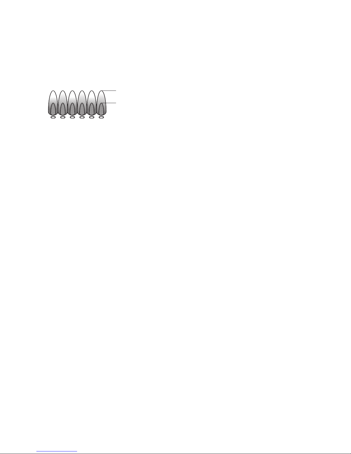
Burner Flame Check
General Grill Cleaning
• Remove cooking grates and heat diffusers. Light
burners, rotate knobs from HIGH to LOW. You should
see a smaller flame in LOW position than seen on
HIGH. Perform burner flame check on sideburner,
also. Always check flame prior to each use. If only
low flame is seen refer to "Sudden drop or low
flame" in the Troubleshooting Section.
HIGH
LOW
Turning Grill Off
• Turn all knobs to the OFF position. Turn off Natural
Gas source.
Ignitor Check
• Turn gas off at source. Press and hold electronic
ignitor button. "Click" should be heard and spark
seen each time between each collector box or
burner and electrode. See "Troubleshooting" if no
click or spark.
Valve Check
• Important: Make sure gas is off at source before
checking valves. Knobs lock in OFF position. To
check valves, first push in knobs and release, knobs
should spring back. If knobs do not spring back,
replace valve assembly before using grill. Turn knobs
to LOW position then turn back to OFF position.
Valves should turn smoothly.
Hose Check
• Before each use, check to see if hoses are cut or
worn or kinked. Replace damaged hoses before
using grill. Use only valve/hose specified by
manufacturer.
• Do not mistake brown or black accumulation of
grease and smoke for paint. Interiors of gas grills
are not painted at the factory (and should never be
painted). Apply a strong solution of detergent and
water or use a grill cleaner with scrub brush on
insides of grill lid and bottom. Rinse and allow to
completely air dry. Do not apply a caustic grill/oven
cleaner to painted surfaces.
• Plastic parts: Wash with warm soapy water and
wipe dry. Do not use citrisol, abrasive cleaners,
degreasers or a concentrated grill cleaner on plastic
parts. Damage to and failure of parts can result.
• Porcelain surfaces: Because of glass-like composition,
most residue can be wiped away with baking
soda/water solution or specially formulated cleaner.
Use nonabrasive scouring powder for stubborn
stains.
• Painted surfaces: Wash with mild detergent or
nonabrasive cleaner and warm soapy water. Wipe
dry with a soft nonabrasive cloth.
• Stainless steel surfaces: To maintain your grill’s high
quality appearance, wash with mild detergent and
warm soapy water and wipe dry with a soft cloth
after each use. Baked-on grease deposits may
require the use of an abrasive plastic cleaning pad.
Use only in direction of brushed finish to avoid
damage. Do not use abrasive pad on areas with
graphics.
• Cooking surfaces: If a bristle brush is used to clean
any of the grill cooking surfaces, ensure no loose
bristles remain on cooking surfaces prior to grilling.
It is not recommended to clean cooking surfaces
while grill is hot.
466226313 • 13
Page 14
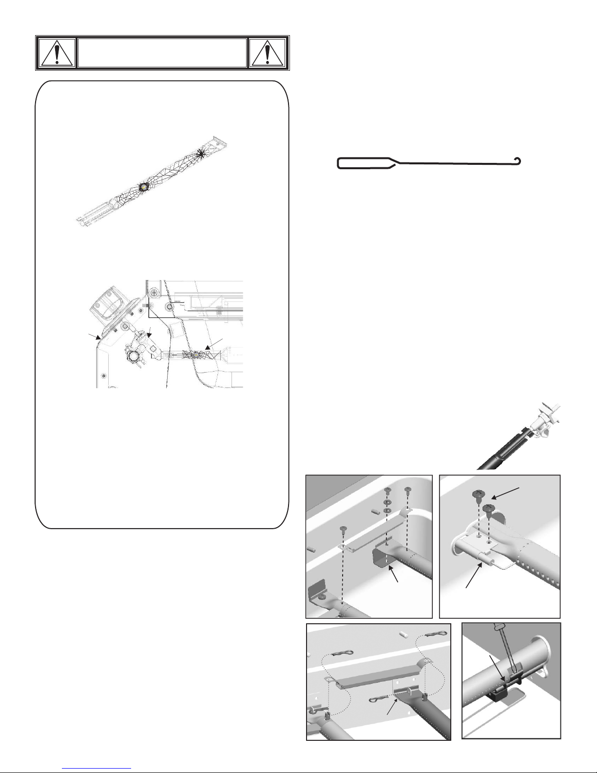
CAUTION
SPIDER ALERT!
Important: Always ensure that the venturi burner tubes are clean. A
venturi burner tube has a narrow area in which spiders tend to build
nests.
4. Detach electrode from burner.
NOTE: Removal/Detachment method will depend
on the burner configuration. See different
configurations in illustrations below.
5. Carefully lift each burner up and away from valve
openings. We suggest three ways to clean the
burner tubes. Use the one easiest for you.
(A) Bend a stiff wire (a light weight coat hanger
works well) into a small hook. Run the hook
through each burner tube several times.
SPIDER AND WEBS
INSIDE BURNER TUBE
If you notice that your grill is getting hard to light or that the
flame isn’t as strong as it should be, take the time to check and
clean the burner tubes.
CONTROL PANEL
VALVE
Spiders or small insects have been known to create “flashback”
problems. The spiders spin webs, build nests and lay eggs in the
grill’s venturi tube(s) obstructing the flow of gas to the burner.
The backed-up gas can ignite in the burner tube behind the
control panel. This is known as a flashback and it can damage
your grill and even cause injury.
To prevent flashbacks and ensure good performance the burner
and venturi tube assembly should be removed from the grill
and cleaned before use whenever the grill has been idle for an
extended period.
SPIDER WEBS
INSIDE VENTURI TUBE
BURNER
(B) Use a narrow bottle brush with a flexible
handle (do not use a brass wire brush), run the
brush through each burner tube several times.
(C) Wear eye protection: Use an air hose to force
air into the burner tube and out the burner
ports. Check each port to make sure air comes
out each hole.
6. Wire brush entire outer surface of burner to remove
food residue and dirt.
7. Clean any blocked ports with a stiff wire such as an
open paper clip.
8. Check burner for damage, due to normal wear and
corrosion some holes may become enlarged. If any
large cracks or holes are found replace burner.
VERY IMPORTANT: Burner tubes must reengage
valve openings. See illustrations at right.
9. Attach electrode to burner.
10. Carefully replace burners.
11. Attach burners to brackets on firebox.
12. Reposition carryover
tubes and attach to
burners. Replace heat
Correct
burner-to-valve
engagement
diffusers and cooking
grates.
Remove screws
Firebox
Storing Your Grill
• Clean cooking grates.
• Store in dry location.
• Cover grill if stored outdoors. Choose from a variety
of grill covers offered by manufacturers.
• When removing grill from storage, follow “Cleaning
the Burner Assembly” instructions before starting
grill.
Cleaning the Burner Assembly
Follow these instructions to clean and/or replace parts
of burner assembly or if you have trouble igniting
grill.
1. Turn gas OFF at control knobs and source.
2. Remove cooking grates and heat diffusers.
3. Remove carryover tubes and burners.
14 • 466226313
Firebox
Carryover tube
Firebox
burner
bracket
Carryov
Firebox burner
bracket
er tube
Electrode
Electrode
Pry off electrode
with a flat blade
screwdriver
Page 15
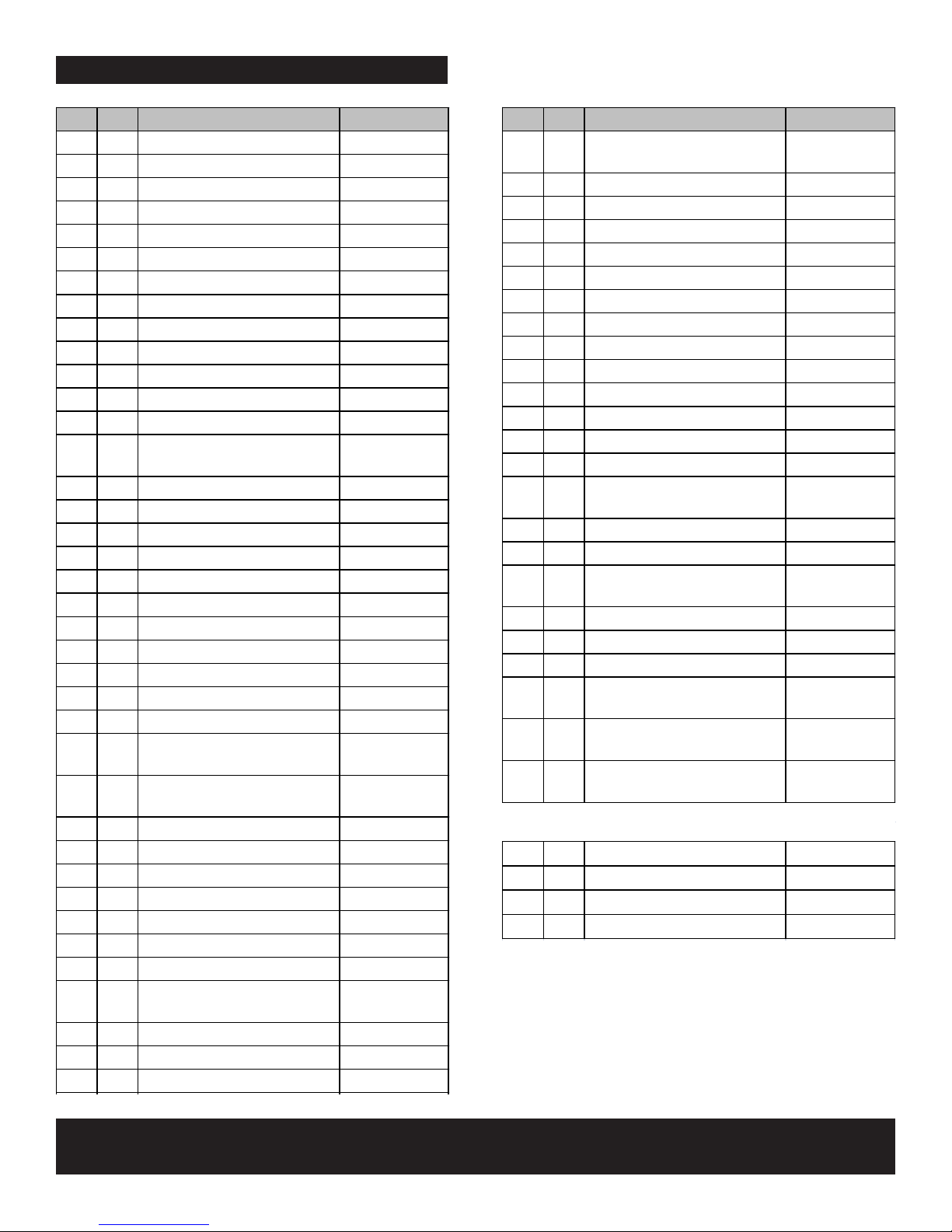
PARTS LIST
Ke y Qty De s c ription Part #
1 1 BOTTOM SHELF
G651-0055-W1
2 1 LEFT SIDE CART PANEL
G651-2200-W1A
3 1 RIGHT SIDE CART PANEL
G651-2300-W1A
4 2 MATCH HOLDER
G401-0079-W1
5 4 CASTER SOCKET
G408-0036-W1
6 1 LOWER BACK PANEL
G651-7701-W1
7 1 FRONT DOOR BRACE
G651-B800-W1
8 2 CASTER, LOCKING
G350-0023-W1
9 2 CASTER, FIXED
G350-0024-W1
10 1 WEIGHT BLOCK
G651-0012-W1
11 1 TOP LID
G651-4200-W1
12 1 LOGO PLATE F/ LID
G528-0002-W2
13 1 TEMPERATURE GAUGE
G430-0022-W1
14 1
BEZEL, F/ TEMPERATURE
GAUGE
G404-0034-W1
15 2 LID BUMPER, RECTANGLE
G430-00B8-W1
16 2 LID BUMPER, ROUND
G303-0038-W1
17 1 TOP LID HARDWARE
G430-0024-W2
18 1 HANDLE, F/ LID
G651-0008-W1
19 1 FIREBOX
G651-C300-W2
20 5 MAIN BURNER-TUBE BURNER
G651-4000-W1A
21 1 MAIN BURNER-BAR BURNER
G651-4100-W1
22 1 ELECTRODE, F/ MAIN BURNER
G501-0010-W1
23 1 ELECTRODE, F/ SEAR BURNER
G651-5103-W2
24 4 CARRY OVER TUBE
G501-0015-W1
25 1 CONTROL PANEL, MAIN
G651-0053-W1
26 1 ELECTRONIC IGNITION
MODULE
G651-1300-W1
27 1 HEAT SHIELD, F/ IGNITION
MODULE
G308-0025-W1
28 1 HOSE VALVE ASSEMBLY
G651-Q100-W1
29 7 BEZEL F/ CONTROL KNOB
G430-0027-W2
30 7 CONTROL KNOB
G432-0010-W1
31 1 RIGHT SIDE SHELF
G530-0500-W2
32 1 FASCIA, F/ RIGHT SHELF
G651-P901-W1
33 1 LEFT SIDE SHELF F/ SB
G530-0600-W2
34 1 DRIP PAN, F/ SB
G516-0021-W2
35 2 RUBBER BUMPER, F/
SIDEBURNER
G501-0066-W1
36 1 CONTROL PANEL, F/ SB
G651-Q001-W1
37 1 SIDEBURNER
G651-R700-W1
38 1 ELECTRODE, F/ SB
G515-0039-W1
Ke y Qty De s c ription Part #
39 1
ELECTRODE WIRE, F/
SIDEBURNER
G602-0007-W1
40 1 SIDEBURNER VALVE CLIP
G405-0019-W1
41 1 SIDEBURNER LID
G521-0021-W1
42 1
HINGE, F/ SIDEBURNER G513-1100-W1
43 1
HANDLE, F/ SB LID G517-0011-W2
44 1 SIDEBURNER GRATE
G606-0015-W1
45 1
GRIDDLE, F/ SIDEBURNER G516-0070-W1
46 2 HANDLE, F/ DOOR
G651-0006-W2
47 1 LEFT DOOR
G651-5501-W1
48 1 RIGHT DOOR
G651-5601-W1
49 2 DOOR PIN, FIXED
G401-0053-W1
50 2 DOOR PIN, SPRING
G439-0036-W2
51 2 MAGNET ASSEMBLY
G213-0022-W1
52 5 HEAT DIFFUSER
G430-0005-W1
53 1 HEAT DIFFUSER F/ BAR
BURNER
G651-0011-W1
54 4 COOKING GRATE
G432-0002-W1
55 1 WARMING RACK
G651-0017-W1
56 1 BUTTON, F/ IGNITION
MODULE
G409-0030-W1
57 1 GREASE TRAY
G651-3900-W1
58 1 GREASE PAN
G416-0015-W1
59 1
NATURAL GAS HOSE G501-0099-W1
60 1 ROTISSERIE BRACKET,
MOTOR SIDE
G651-0020-W1
61 1 ROTISSERIE BRACKET,
HANDLE SIDE
G651-0021-W1
62 1 ROTISSERIE MOTOR W/ FORK
ASSEMBLY
G651-0054-W1
… 1 CASTER PIN
G350-0026-W1
… 1 PRODUCT MANUAL, ENGLISH
G651-250801-W1
… 1 PRODUCT MANUAL, FRENCH
G651-250802-W1
… 1 HARDWARE PACK
G65125-B001-W1
NOT Pictured
NOTE: Some grill parts shown in the assembly steps may differ slightly in appearance from
those on your particular grill model. However, the method of assembly remains the same.
To order replacement par ts after using grill,
call 1-800-241-7548.
466226313 • 15
Page 16
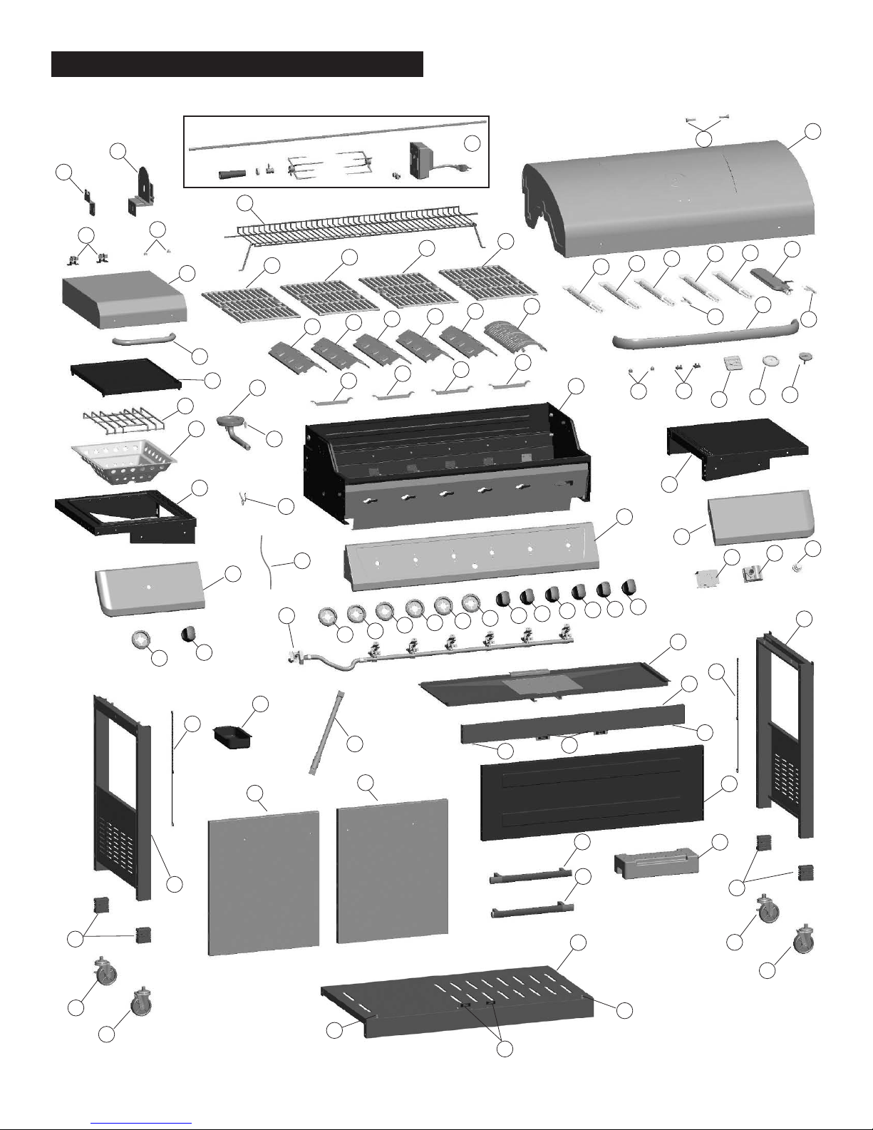
PARTS DIAGRAM
61
42
60
35
41
44
43
34
33
45
36
55
37
54
38
40
39
52
54
24
52
52
24
54
52
24
62
52
54
24
53
19
20
25
20
16
20
31
32
15
17
20
22
12
27
20
14
18
26
11
21
23
13
56
29
30
3
57
29
30
28
29
29
29
29
29
30
30
30
30
30
4
7
58
4
47
59
50
48
51
46
2
5
46
1
50
6
10
5
8
9
8
9
49
49
51
16 • 466226313
Page 17
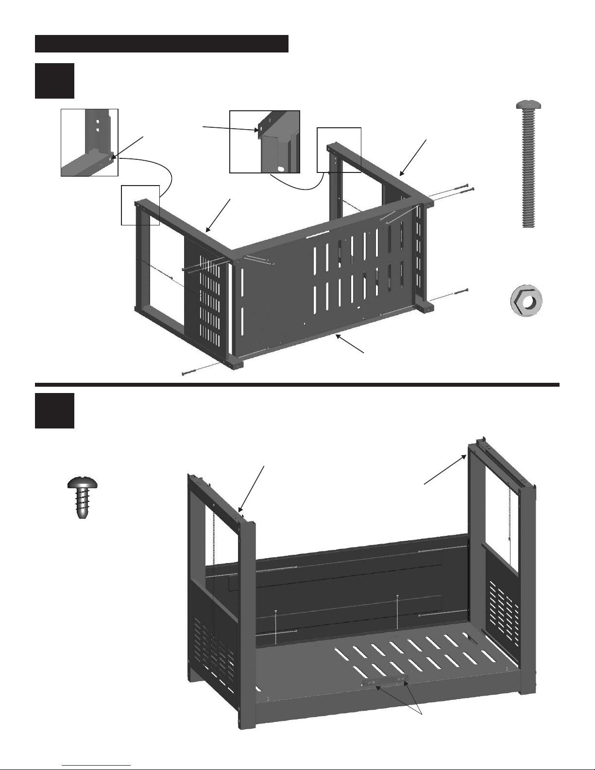
ASSEMBLY
• Attach bottom shelf, oriented as shown, to left and right leg assemblies with 1/4-20x2-3/8” machine screws and 1/4-20
11
flange nuts.
2
For Front Door
Brace Assembly
Left Side Panel
Front
Rear
Bottom Shelf
Right Side Panel
1/4-20x2-3/8"
Machine Screw
Qty: 6
1/4-20
Flange Nut
Qty: 6
• Place lower back panel between side panels as shown. Attach to left and right side panels with (4) #8x3/8” sheet metal
screws. Then attach to bottom shelf with (2) #8x3/8” sheet metal screws.
#8x3/8"
Sheet Metal Screws
Qty. 6
Left Side Panel
Right Side Panel
Lower Back Panel
Bottom Shelf
Magnet Assembly
466226313 • 17
Page 18
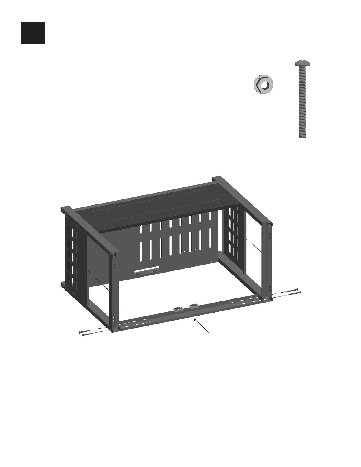
3
• Place front door brace as shown. Attach to left and right leg assemblies with 1/4-20x2-3/8" machine screws and
1/4-20 flange nuts.
1/4-20
Flange Nut
Qty: 4
1/4-20x2-3/8"
Machine Screw
Qty: 4
18 • 466226313
Front Door Brace
Page 19
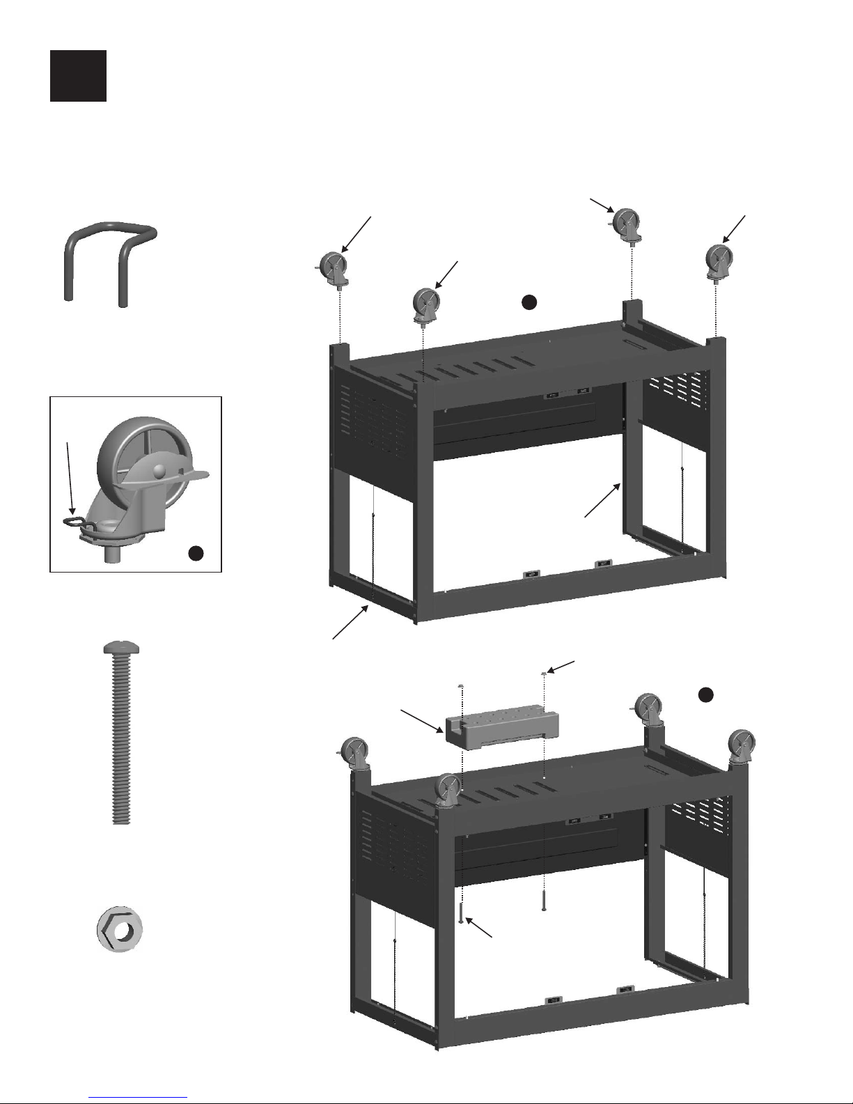
4
Caster Pin
Caster Pin
• Turn assembly upside down.
• Insert Caster Pin into the caster mounting plate to lock it in place, shown A. Spin the caster clockwise into the threads on
the bottom shelf until secure. Remove the Caster Pin and repeat for remaining casters. Make sure the two locking casters
are secured at the rear and the non-locking casters are secured at the front (B). After all 4 casters are secure remove the
Caster Pin and save for future maintenance.
• Attach weight block to bottom shelf with (2) 1/4-20x2” machine screws and 1/4-20 flange nuts (C).
Locking Caster
Locking Caster
Fixed Caster
B
Rear
Front
Fixed Caster
1/4-20x2"
Machine Screw
Qty: 2
Left Leg Assembly
A
Right Leg Assembly
Weight Block
1/4-20 Flange Nut
C
1/4-20
Flange Nut
Qty: 2
1/4-20x2"
Machine Screw
466226313 • 19
Page 20
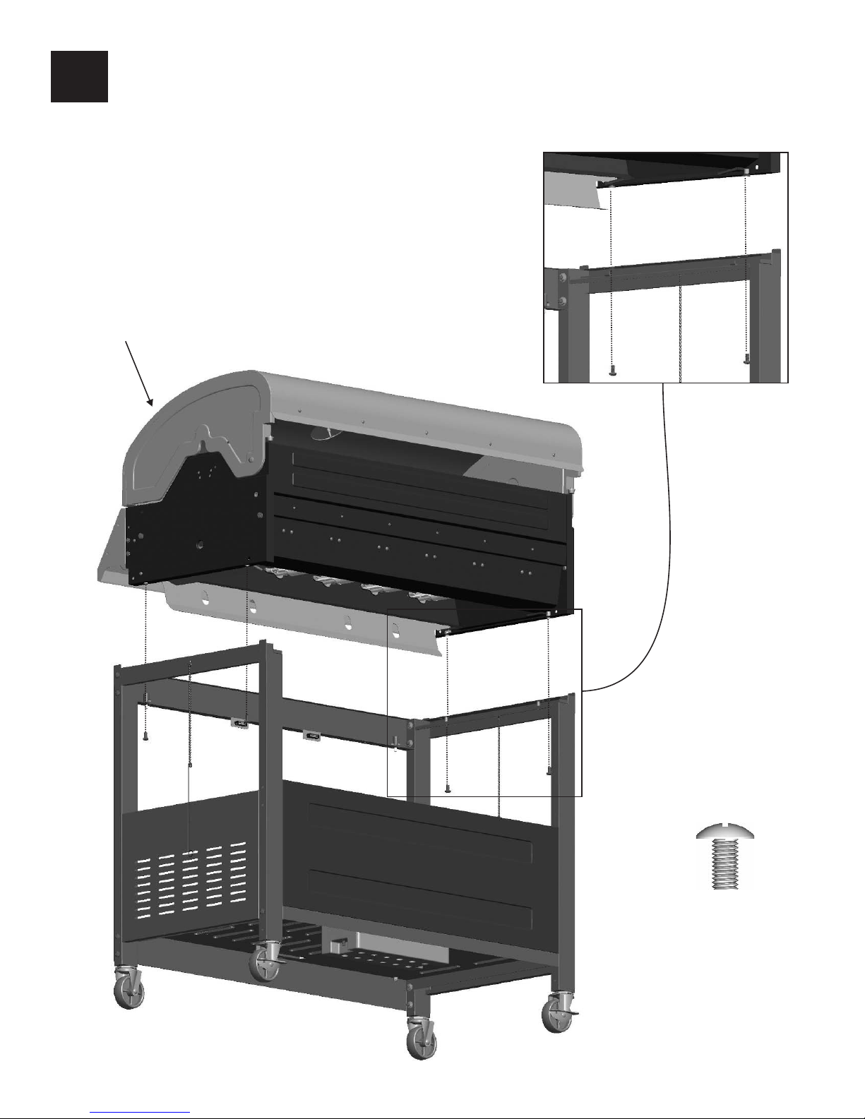
5
• Stand cart upright.
• This step requires two people to lift and position grill head onto cart.
• Carefully lower the grill head onto the cart. Attach with 1/4-20x1/2" screws.
Grill Head
20 • 466226313
1/4-20x1/2" Screw
Qty: 4
Page 21
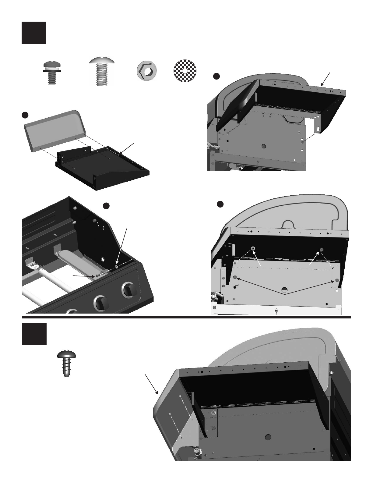
6
• Attach right side fascia to right side shelf with #10-24x3/8" screw assemblies (A).
• Hook the right side shelf to firebox by the pre-assembled screws (B).
• Inside firebox, insert 7mm fiber washer and 1/4-20x1/2” screw as shown (C).
• Attach shelf with 1/4-20x1/2" screw and 1/4-20 flange nuts, and fasten the two pre-assembled screws (D).
Right Side Shelf
B
#10-24x3/8" screw
assembly
Qty. 3
A
1/4-20x1/2"
Machine Screw
Qty. 2
C
1/4-20
Flange Nut
Qty. 1
#10-24x3/8" screw
assembly
7mm
Fiber Washer
7mm
Fiber Washer
Qty. 1
D
1/4-20x1/2"
Screw
• Attach fascia to firebox with #8x3/8” sheet metal screws.
7
#8x3/8"
Sheet Metal Screws
Qty. 2
Fascia,
Right Side Shelf
1/4-20
Flange Nut
Tighten the screws
1/4-20x1/2"
Screw
466226313 • 21
Page 22
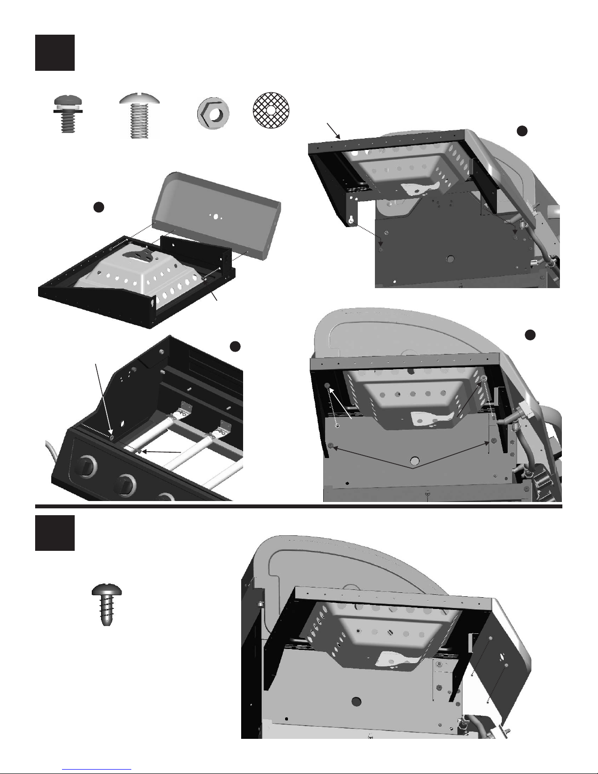
• Attach left side fascia to left side shelf with #10-24x3/8" screw assemblies (A).
8
• Hook the side burner shelf to firebox by the pre-assembled screws (B).
• Inside firebox, insert 7mm fiber washer and 1/4-20x1/2” screw as shown (C).
• Attach shelf with 1/4-20x1/2" screw and 1/4-20 flange nuts, and fasten the two pre-assembled screws (D).
#10-24x3/8"
screw assembly
Qty. 3
7mm
Fiber Washer
1/4-20x1/2"
Machine Screw
Qty. 2
A
1/4-20
Flange Nut
Qty. 1
#10-24x3/8" screw
Fiber Washer
assembly
C
Side Burner Shelf
B
7mm
Qty. 1
D
• Attach fascia to firebox with #8x3/8” sheet metal screws.
9
sheet metal screws
#8x3/8"
Qty. 2
1/4-20x1/2"
Screw
1/4-20x1/2"
Screw
Tighten the screws
1/4-20
Flange Nut
22 • 466226313
Page 23
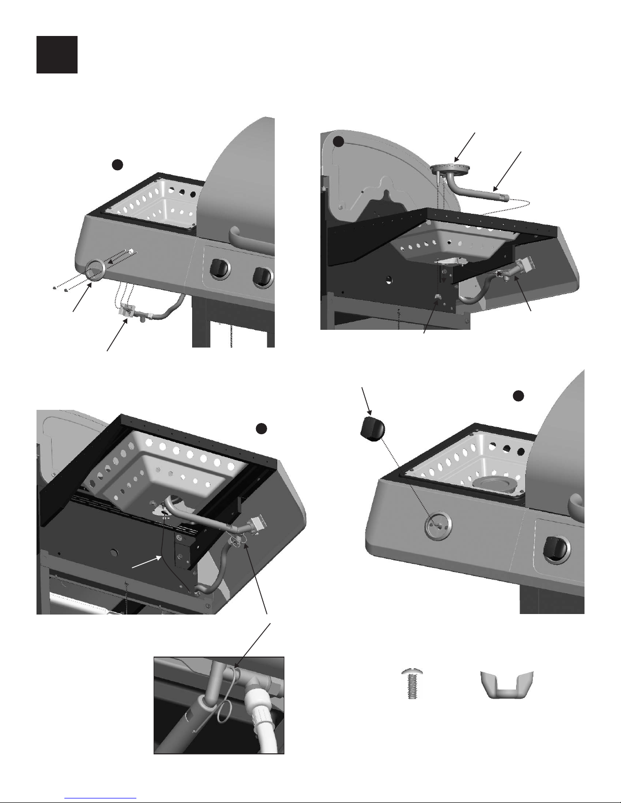
10
• Attach side burner bezel and valve with #8-32x3/8” Stainless Steel screws. (A).
• Place side burner into shelf. Make sure valve is inside side burner tube. Attach side burner with #8 wing nut (B). Hook
venturi clip to side burner tube and around manifold. Attach side burner ignitor wire to ignitor as shown (C).
• Press side burner control knob onto valve stem (D).
Side Burner
B
A
Side Burner Tube
Side Burner Bezel
Side Burner Valve
Sideburner
Ignitor Wire
Valve
#8 wing nut
Side Burner Control Knob
D
C
Burner Tube
Valve
Venturi Clip
#8-32X3/8”
Stainless Steel Screw
Qty. 2
#8 Wing Nut
Qty. 1
466226313 • 23
Page 24
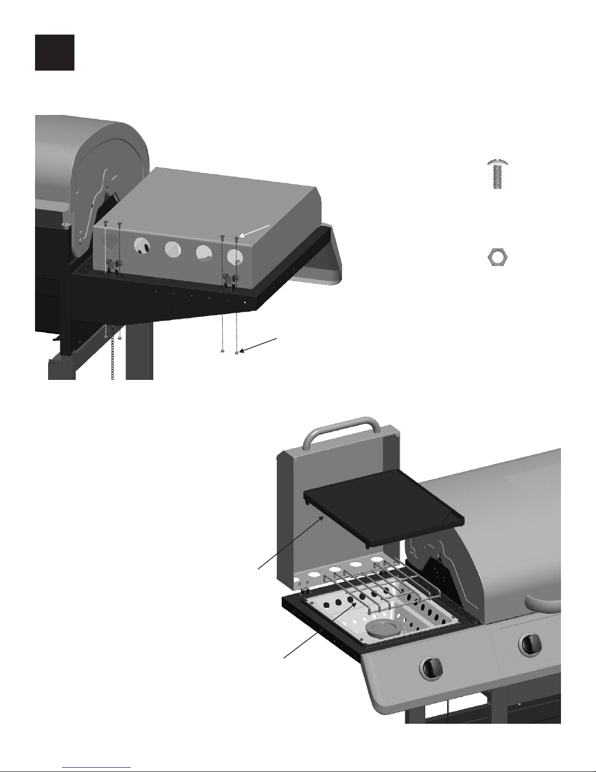
11
• Place side burner lid onto left side shelf and align hinges holes in back of lid with side shelf holes. Attach side burner lid
assembly to side shelf with #8-32 x3/8" screws and #8-32 hex nuts.
• Place side burner cooking grate and griddle onto side burner shelf.
#8-32X3/8” Screw
#8-32x3/8"
Screw
Qty. 4
#8-32 Hex Nut
Qty. 4
Side Burner Griddle
#8-32 Hex Nut
Side Burner Cooking Grate
24 • 466226313
Page 25
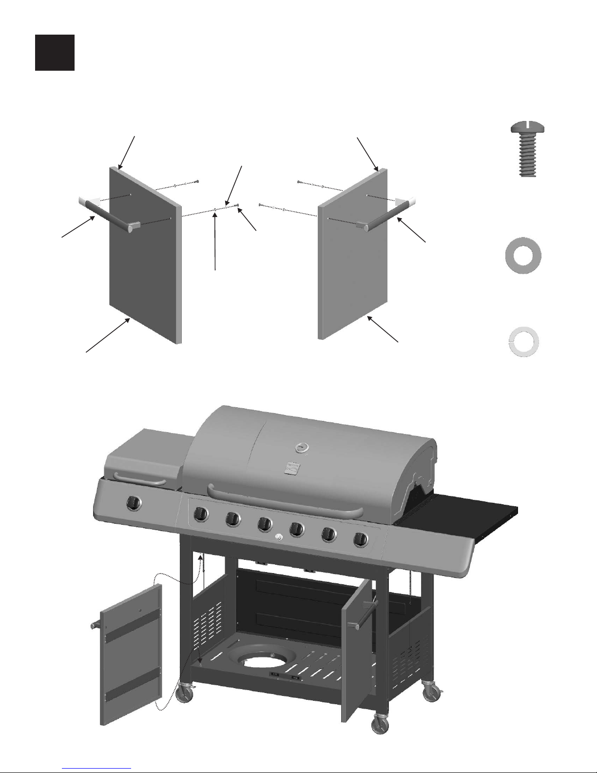
12
• Attach handle to door with #10-24x1/2” machine screws, 5mm flat washers and 5mm lock washers (A).
• Insert hinge pin on bottom shelf into hole in door. Press upper hinge pin in front door brace, align hinge hole on top of
door, and release hinge pin into door.
Left Handle
Left Door
Hinge Pin hole
5mm Lock Washer
#10-24x1/2"
Machine Screw
5mm Flat Washer
A
Hinge Pin hole
#10-24x1/2"
Machine Screw
Qty. 4
Right Handle
5mm Flat Washer
Qty. 4
Right Door
5mm Lock Washer
Qty. 4
466226313 • 25
Page 26
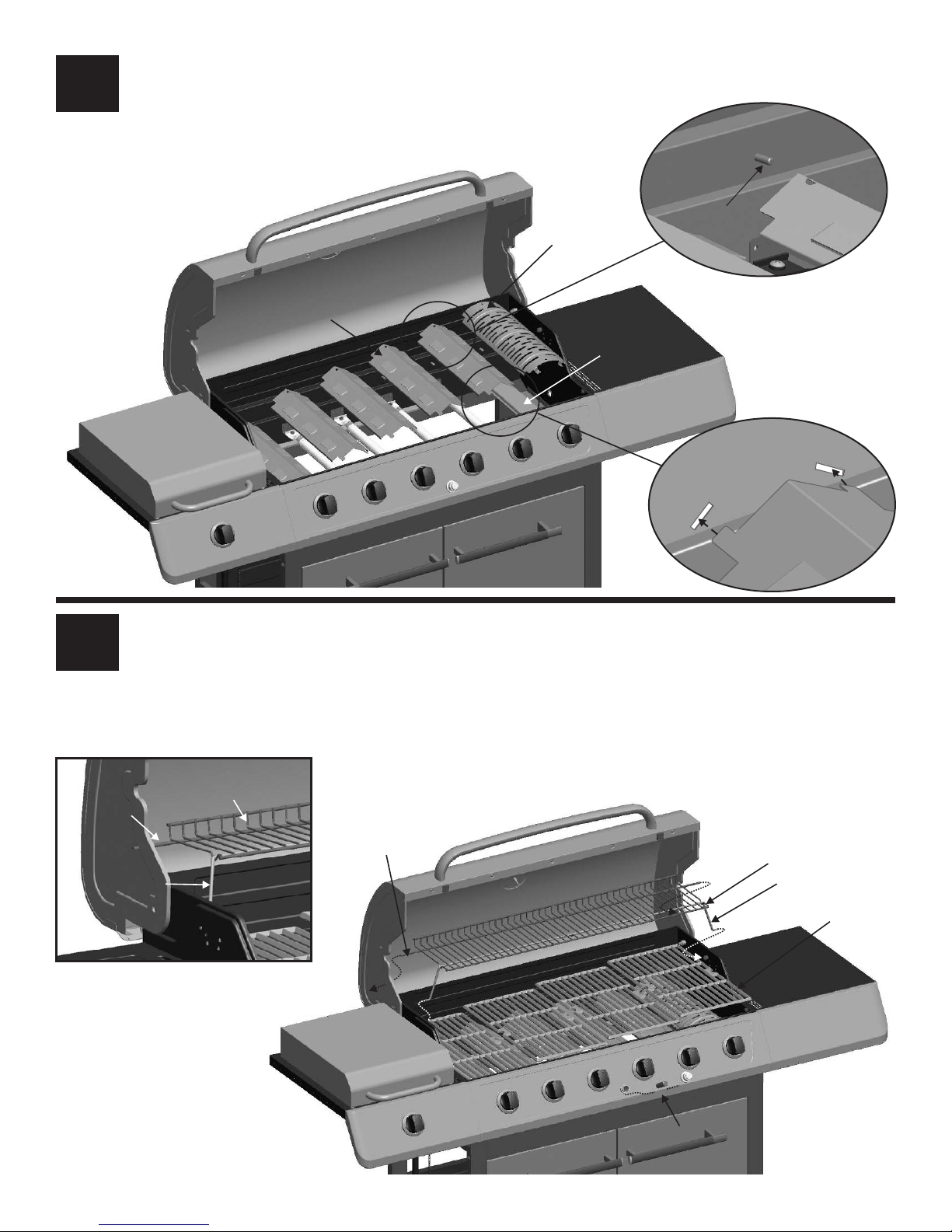
13
• Place heat diffusers over tube burners and the heat diffuser for sear burner over sear burner by inserting tabs into slots
in front of firebox. Opposite ends of heat diffusers rest on pins in back of firebox.
Back of Firebox
14
Heat Diffuser
Heat Diffuser
Heat Diffuser
(Black)
Heat Diffuser,
F/Sear Burner
(Stainless Steel)
Sear Burner
Pin
Front of Firebox
• Place cooking grates onto grate rests.
• Insert ends of Warming Rack pivot wire into holes in sides of gril lid. Insert ends of Warming Rack leg wire into holes in
sides of firebox.
NOTE: Pivot and leg wires, running side-to-side, should be under wires running front-to-back. If pivot and leg wires are
on top, Warming Rack is installed upside-down.
• Unscrew ignitor cap and place AA battery into ignitor slot with positive end (+) facing outward. Screw ignitor cap onto
ignitor.
Pivot Wire
(side to side)
Leg Wire
(side to side)
26 • 466226313
Warming Rack Wires
(front-to-back)
Pivot Wire
Warming Rack
Leg Wire
Cooking Grate
+
+
–
AA Battery
Page 27
16
15
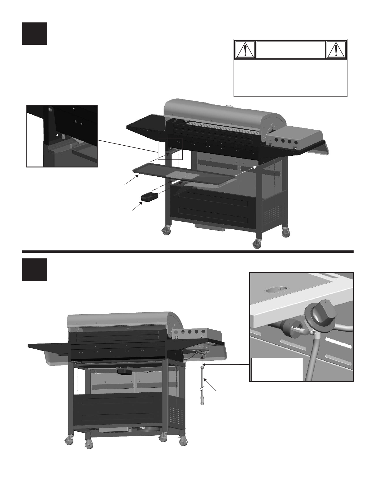
• Place grease pan into grease tray, then place the tray into the cart.
CAUTION
Failure to install grease tray and
grease pan will cause hot grease to
drip from bottom of grill with risk of
fire or property damage.
Grease Tray
16
Grease Pan
• Attach natural gas hose as shown.
NOTE: Sideburner
shelf fascia not
shown for clarity.
Natural Gas Hose
466226313 • 27
Page 28
17
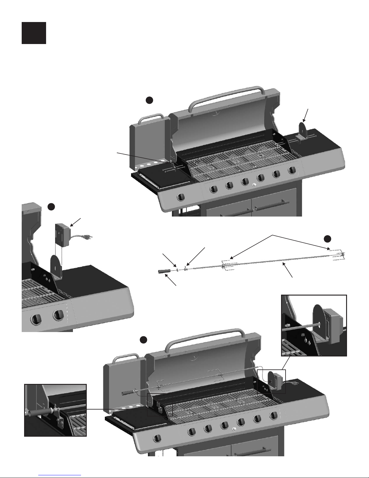
• Remove the warming rack and open the side burner lid before assembling rotisserie.
• Remove the pre-assembled screws, fiber washers and flange nuts from rotisserie brackets. Then attached the handle side
rotisserie bracket to left and motor side rotisserie bracket to right side of firebox, as shown A.
• Push rotisserie motor onto the motor side rotisserie bracket, as shown B.
• Insert the rotisserie bushing and rotisserie washer to the threaded end of the spit rod. Attached the rotisserie handle.
Insert the spit rod through rotisserie forks, as shown C.
• Insert the motor end of the spit rod into the socket of the rotisserie motor. Rest the groove of the rotisserie bushing onto
the handle side rotisserie brakcet, as shown D.
A
Rotisserie Bracket,
Handle Side
B
Rotisserie Motor
Rotisserie Fork
Rotisserie Bushing
Rotisserie Washer
Rotisserie Bracket,
Motor Side
C
Rotisserie Handle
D
Spit Rod
28 • 466226313
Page 29
Rotisserie Operation Instructions
Use only a Ground Fault Interrupter (GFI) protected circuit
with this rotisserie motor.
1. Make sure power switch on the rotisserie motor is in the
“OFF” position.
2. Connect rotisserie motor plug to an extension cord, then
put the extension cord plug into the outlet on the wall.
3. After placing the spit rod as stated in the assembly
instructions, turn the rotisserie motor to “ON”.
WARNING
Electrical Grounding Instructions:
This appliance is equipped with a three prong (grounded)
plug for your protection against shock hazard and should
be plugged directly into a properly grounded three prong
receptacle. Do not cut or remove the grounding prong
from this plug.
WARNING
WARNING
• Keep any electrical supply cord away from any heated
surface.
• Use the shortest length extension cord required. Do not
connect 2 or more extension cords together.
Important Safeguards
Please use the following basic safety precautions when
using your rotisserie.
1. Read all instructions before attempting assembly,
installation and use.
2. Do not allow children to operate this product. Provide
close supervision if used near children.
3. Do not touch hot surfaces without proper protection.
4. Allow all parts to cool before assembling or
disassembling.
5. Do not use accessory attachments unless recommended
by Char-Briol.
6. Do not operate for any use other than intended.
7. Removed motor from grill and store indoors when not in
use.
8. Do not use grill for non-rotissorie cooking with motor
installed.
9. To protect against electric shock, do not immerse motor,
cord or plugs in water or other liquid
10. Do not operate any outdoor cooking gas appliance with
a damaged cord, plug, or after the appliance
malfunctions or has been damaged in any manner.
Contact the manufacturer for replacement parts.
11. Do not allow cord to touch hot surfaces.
12. Unplug cord from outlet when not in use and before
cleaning.
13. Turn motor OFF before removing plug from outlet.
When using and extension cord, for your safety:
• Use only outdoor type with three prong grounding plug,
approved by UL, marked with a W-A and with a tag
stating “Suitable for Use with Outdoor Appliance”.
• Keep connections dry and off ground.
• Do not let cord hang over edge of table or other items
where it can be pulled by children or tripped over.
466226313 • 29
Page 30
EMERGENCIES: If a gas leak cannot be stopped, or a fire occurs due to gas leakage, call the fire department.
Emergencies
Gas leaking from
cracked/cut/burned
hose.
Gas leaking between
gas inlet pipe and
quick disconnect
socket.
Fire coming through
control panel.
Grease fire or
continuous excessive
flames above cooking
surface.
Possible Cause
• Damaged hose.
• Improper installation, connection not
tight, failure of pipe joint compound or
teflon tape.
• Fire in burner tube section of burner
due to blockage.
• Too much grease buildup in burner
area.
Prevention/Solution
• Turn off gas at source on natural gas systems. If the hose is
cracked or cut but not burned, simply replace the hose with an
approved replacement from the manufacture. If the hose is
burned, the cause could be other than a faulty hose. Discontinue
use of grill until a plumber or gas technician has investigated
and corrected the problem.
• Turn off Natural Gas at source. Remove quick disconnect socket
and visually inspect for damage. Re-apply pipe joint compound
or approved teflon tape.
• Turn off control knobs and Natural Gas at source. Leave lid
open to allow flames to die down. After fire is out and grill is
cold, remove burner and inspect for spider nests or rust. See
Spider Alert and Cleaning the Burner Assembly sections of this
Use & Care Guide.
• Turn off control knobs and source. Leave lid open to allow
flames to die down. After cooling, clean food particles and
excess grease from inside firebox area, grease tray, and other
surfaces.
Troubleshooting
Problem
Burner(s) will not light
using ignitor.
(See Electronic Ignition
Troubleshooting also)
Continued on next
page.
Possible Cause
GAS ISSUES:
• Trying to light wrong burner.
• Burner not engaged with control valve.
• Obstruction in burner.
• No gas flow.
ELECTRICAL ISSUES:
• Electrode cracked or broken; “sparks at
crack.”
• Electrode tip not in proper position.
• Wire and/or electrode covered with
cooking residue.
• Wires are loose or disconnected.
Prevention/Solution
• See instructions on control panel and in Use and Care section.
• Make sure valves are positioned inside of burner tubes.
• Ensure burner tubes are not obstructed with spider webs or other
matter. See cleaning section of Use and Care.
• Make sure Natural Gas source is turned on.
• Replace electrode(s).
Main Burners:
• Tip of electrode should be pointing toward gas port opening on
burner. The distance should be 1/8” to 1/4”. Adjust if necessary.
Side burner:
• Tip of electrode should be pointing toward gas port opening on
burner. the distance should be 1/8” to 3/16”. Adjust if necessary.
• Clean wire and/or electrode with rubbing alcohol and clean
swab.
• Reconnect wires or replace electrode/wire assembly.
• Wires are shorting (sparking) between
ignitor and electrode.
• Dead battery.
30 • 466226313
• Replace ignitor wire/electrode assembly.
• Replace with a new AA-size alkaline battery.
Page 31
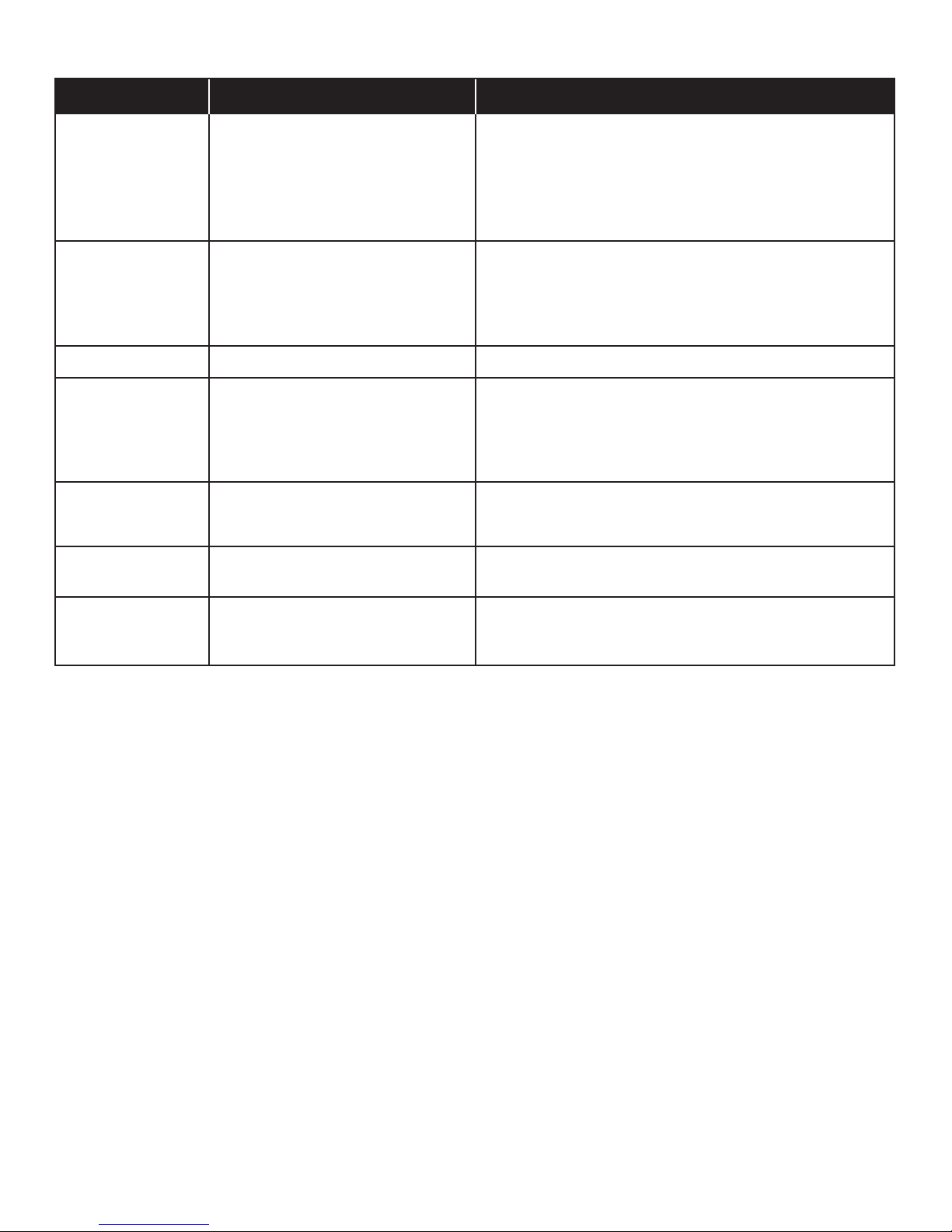
Troubleshooting (continued)
Problem
Burner(s) will not light
using ignitor.
(See Electronic Ignition
Troubleshooting also)
Burner(s) will not
match light.
Flames blow out.
Flare-up.
Persistent grease fire.
Possible Cause
ELECTRONIC IGNITION:
• No spark, no ignition noise.
• No spark, some ignition noise.
• Sparks, but not at electrode or at full
strength.
• See “GAS ISSUES:” on previous page.
• Match will not reach.
• Improper method of match-lighting.
• High or gusting winds.
• Grease buildup.
• Excessive fat in meat.
• Excessive cooking temperature.
• Grease trapped by food buildup
around burner system.
Prevention/Solution
• See Section I of Electronic Ignition System.
• See Section II of Electronic Ignition System.
• See Section III of Electronic Ignition System.
• Use long-stem match (fireplace match).
• See “Match-Lighting” section of Use and Care.
• Turn front of grill to face wind or increase flame height.
• Clean burners and inside of grill/firebox.
• Trim fat from meat before grilling.
• Adjust (lower) temperature accordingly.
• Turn knobs to OFF. Turn gas off at source. Leave lid in open
position and let fire burn out. After grill cools, remove and clean
all parts.
Flashback...
(fire in burner tube(s)).
One burner does not
light from other
burner(s).
• Burner and/or burner tubes are
blocked.
• Grease buildup or food particles in
end(s) of carryover tube(s).
• Turn knobs to OFF. Clean burner and/or burner tubes. See
burner cleaning section of Use and Care.
• Clean carry-over tube(s) with wire brush.
466226313 • 31
Page 32
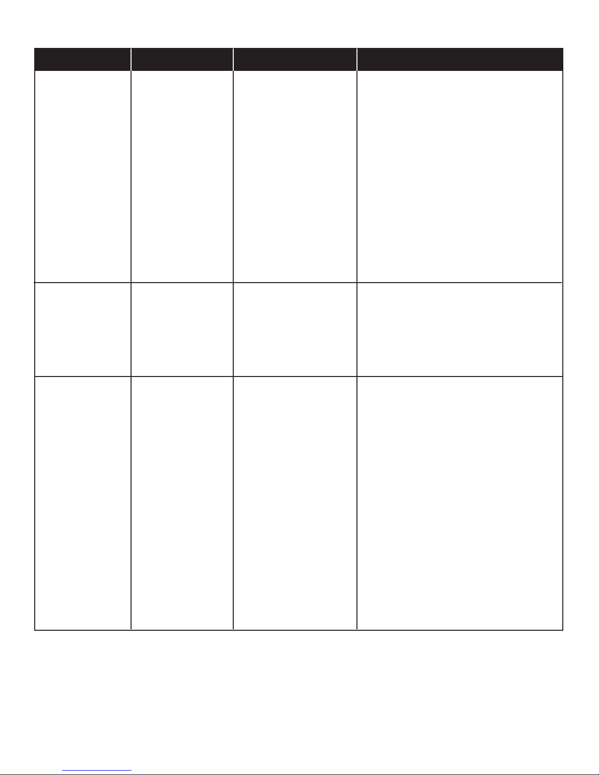
Troubleshooting - Electronic Ignition
Problem (Ignition)
SECTION I
No sparks appear at
any electrodes when
Electronic Ignition
Button is pressed; no
noise can be heard
from spark module.
SECTION II
No sparks appear at
any electrodes when
Electronic Ignition
Button is pressed; noise
can be heard from
spark module.
Possible Cause
• Battery not installed
properly.
• Dead battery.
• Button assembly not
installed properly.
• Faulty spark module.
• Output lead
connections not
connected.
Check Procedure
• Check battery orientation.
• Has battery been used
previously?
• Check to insure threads are
properly engaged. Button
should travel up and down
without binding.
• If no sparks are generated
with new battery and good
wire connections, module is
faulty.
• Are output connections on
and tight?
Prevention/Solution
• Install battery (make sure that “+” and “–”
connectors are oriented correctly, with “+” end up
and “–” end down.)
• Replace battery with new AA-size alkaline battery.
• Unscrew button cap assembly and reinstall,
making sure threads are aligned and engaged
fully.
• Replace spark module assembly.
• Remove and reconnect all output connections at
module and electrodes.
SECTION III
Sparks are present
but not at all
electrodes and/or not
at full strength
• Output lead
connections not
connected.
• Arcing to grill away
from burner(s).
• Weak battery.
• Electrodes are wet.
• Electrodes cracked or
broken “sparks at
crack”.
• Are output connections on
and tight?
• If possible, observe grill in
dark location. Operate
ignition system and look for
arcing between output wires
and grill frame.
• All sparks present but weak
or at slow rate.
• Has moisture accumulated
on electrode and/or in
burner ports?
• Inspect electrodes for
cracks.
• Remove and reconnect all output connections at
module and electrodes.
• If sparks are observed other than from burner(s),
wire insulation may be damaged. Replace wires.
• Replace battery with a new AA-size alkaline
battery.
• Use paper towel to remove moisture.
• Replace cracked or broken electrodes.
32 • 466226313
Page 33

Notes
466226313 • 33
Page 34

Notes
34 • 466226313
Page 35

Notes
466226313 • 35
Page 36

Get it fixed, at your home or ours!
Your Home
For troubleshooting, product manuals, repair and expert advice:
Please call Grill Service Center for Help and Parts
For English and French service: please call 1-800-241-7548
For repair – in your home – of all major brand appliances,
lawn and garden equipment, or heating and cooling systems,
no matter who made it, no matter who sold it!
For the replacement parts, accessories and
owner’s manuals that you need to do-it-yourself.
For Sears professional installation of home appliances
and items like garage door openers and water heaters.
®
1-800-4-MY-HOME
Call anytime, day or night (U.S.A. and Canada)
www.sears.com www.sears.ca
(1-800-469-4663)
Our Home
For repair of carry-in items like vacuums, lawn equipment,
and electronics, call anytime for the location of your nearest
Sears Parts & Repair Service Center
1-800-488-1222 (U.S.A.) 1-800-469-4663 (Canada)
www.sears.com www.sears.ca
To purchase a protection agreement on a product serviced by Sears:
1-800-827-6655 (U.S.A.) 1-800-361-6665 (Canada)
Para pedir servicio de reparación
a domicilio, y para ordenar piezas:
1-888-SU-HOGAR
(1-888-784-6427)
www.sears.com
® Registered Trademark / TM Trademark of KCD IP, LLC in the United Stat es, or Sears Brands, LLC in other countries
® Marca Registrada / TM Marca de Fábrica de KCD IP, LLC en Estados Unidos, o Sears Brands, LLC in otros países
MC
Marque de commerce / MD Marque déposée de Sears Brands, LLC
®
Au Canada pour service en français:
1-800-LE-FOYER
(1-800-533-6937)
www.sears.ca
MC
 Loading...