

Kenmore 91133359591 Installation Guide
NSTALLATION NSTRUCTIONS FOR YOUR NEW
#00KFOP
Before you begin: F_ead these instructions completely and carefully.
#MPORTANT: Save these _nstructions for local inspector's use.
NMPORTANT: OBSERVE ALL GOVERN!ING CODES AND ORDBNANCES.
gHSTALLEF_: Be sure *o Heave *hese instructions with *he Consumer.
CONSUMER: Keep these _nstructions with your Use and Care Book for future
reference,
o Installation of this cooktop must conform with local
codes or in the absence of local codes with the
National Fuel Gas Code, ANSI Z223 1-Latest edition
WARtII; 8!!iftheinformationin
!
,' Be sure .Four cooktop is installed properly by a
qualified installer or service technician
o To ehminate reaching over surface burners, cabinet
storage above burner should be avoided
o Do not install unit near an outside door or where a
draft may affect its use
This cooktop has been design certihed by the American
Gas Association You'll find safe(y precautions inyour
Use and Care book Read them carefully
o Phillips or blade type o Hand or saber saw
screwdrivers o Pipe wrench
o Pencil o Adjustable wrench
o Ruler and straightedge o Open end wrench
o 7mm socket o 9/32" nut driver
FOR TILE COUNTERTOP INSTALLATION:
O
4 3/!6"X 1 1/4" mason(y screws
t}
Electric drill and a 5/32" drillbit
ADDRTIONAK MATERIAL YOU MAY NEED:
Gas fine shut-off valve
o Pipe joint sealant
o 1/2"pipenipple
For flexible connection where local codes
permit:
o Coated and approved flexible metal tubing (same
3/4" or I/2" t D as gas supply line)
Adaptor or connector
For rigid connection:
o Pipe fittings or union as required
iMPORTANT: Remove"ail packing _
material and literature from thecooMop |
before connecting gas and electrical|
supply to cooktop. |
Pub No 31-I025!
229c4053P083 t
This appliance must be electrically grounded.
Check with your local codes which apply in your area
ff no local codes apply, the Nationa! Electrical Code,
ANSI/NFPA No FO-Latest Edition must be followed
Write to
NA T#O£_AL FHRE PROTECTION
ASSOCHA T#ON
BA TTERYMARCH PARK
QURNCY_ MA 02269
Be sure the instaltahon of this cooktop Ina mobile home
conforms with the Manufactured Home Construction
and Safety Standard, Title 24 CFR, Part 3280 If this
standard does not apply, you must follow the standard
for Manufactured Home In statlations ANSI A225 1and
Manufactured Home Installahons, Site and Communities
and ANSI/NFPA 50 IA or with local codes You can get
a copy of the Federal Standard by writing
Office of Mobile Home Standards
HUD Building
45t 7*h Street_ S. W.
_lashir_gton_ D.C. 240_10
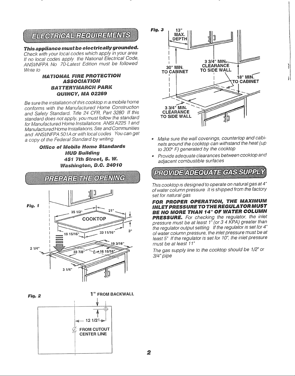
Fig, 3
I
i 3 314"MIN,..-......_
30" MINo CLEARANCE
TO CABINET TO SIDE WALL
,, Make sure the wall coverings, countertop and cabi-
nets around the cooktop can withstand the heat (up
to 200 ° F) generated by the cooktop
o Provide adequate clearances between cooktop and
adjacent combushble surfaces
Fig,
2 114"
Fig. 2
3 114"
I /P_,
t9 3116"
1" FROM BACKWALL
I
This cooktop is designed to operate on natural gas at 4"
of water column pressure It is shipped from the factory
set for natural gas
FOR PROPER OPERA TRON, THE MAXIMUM
BNLET PRESSURE TO THE REGULATOR MUST
BE NO MORE THAN t4" OF WATER COLUMN
PRESSURE, For checking the regulator, the inlet
pressure must be at least 1"(or 3 4 KPA) greater than
the regulator output setting If the regulator is set for 4"
of water column pressure, the infet pressure must be at
least 5" tf the regulator is set for 10" the inlet pressure
must be at least 11"
The gas supply line to the cooktop should be 1/2" or
3/4"pipe
_ FROMCUTOUT
_ CENTER LINE
5
!
2
NoT OpEN TO
11.Connect the cooktop to the gas supply line
2. NEVER REUSEAN OLDCONNECTOR WHEN
nNSTALLBNG A NEW UNIT.
3. The regulator supplied with the unit must be installed
in the gas supply line between the shut-off valve and
the unit connection The top of the regulator should
face toward the cabinet front and be easily acces-
sible through the cab/net doors
4o fnstafl a manual shut-off valve in the gas fine in an
easily accessible location outside the cooktop Be
sure you know how and where to shut off the gas
supply to the cooktop
W4,N Na" ,..,, o,.
connectors. The use of old flexible
connectorscancausegasleaksandpersonal
injury. Alwaysusenew flexible connectors
Fig. 4
19 3/16"
CUTOUT --_
PRESSURE
45°
ELECTRICAL
CORD
34"LONG
....... .............. ...:.......::._.. J
Disconnect _his cooktop and its individual
shut.off valve from the gas supply piping system
during any pressure testing of that system at test
pressures greater than 1/2" psig
gsolate the cooktop from the gas supply piping
system by closing its individual shut-off valve during
any pressure testing of the gas suppty System at test
pressures equal to or less than I/2" psig
INSTAI.I.A TNON OVER BUH.T=IN OVEN
See built-in oven installation for complete installation
instruction
Fig. 5
5"TOCENTER
OF2" DIP.HOLE
FROMCOUNTERTOP
STREETEL
2" DIA.HOLE (207/8"
FROM FRONT OF
COU_Zl"ERTOPTO
ELBOW
CABINETSIDES_
HOLE CENTER)
1/2" PIPE
COUPLING ------_!
J
V
,\
SHUT OFF
5. Check for leaks After connecting cooktop to gas,
check system for leaks with a manometer If a
manometer is not available, turn the gas supply on to
the cooktop and use afiquid leak detector at alljoints
and connections to check for leaks
Tighten aft connections if necessary to prevent gas
leakage in the range or supply #ne
Check alignment of valves after connecting the cooktop
to the gas supply to be sure the manifold pipe has not
been moved A misalignment could cause the valve
knob stem to rub on the control panet, resulting in a gas
leak at the valve
ELECTRICAL
OUTLET
12" BELOW
COUNTERTOP
Because of potential safety hazards under certain
conditions, we strongly recommend against the use of
an extension cord, However, if you still elect to use an
extension cord, it is absolutely necessary that it be a UL
listed three-wire grounding type appliance extension
cord and that the current carrying rating of the cord in
amperes be equivalent to or greater than the branch
circuit rating, Such extension cords are obtainable
through your local appliance dealer
3
i p Rso At rHiS,PP, MOST, i
L ......................... J
An adequate electrical supply and outlet must be used
to operate the electrical parts of your cooktop
t. The power cord of this appliance is equipped with
a three-prong (grounding) plug which must be
used with a properly grounded three-hole outlet
with a standard t20 Volt, 60 cycle AC household
curren t
#
tf you do not have a three-hole grounded outlet,
l_ave a qualified electrician change your old one
3o
A grounding adaptor wil! be needed to convert the
old one until the outlet can be replaced Thismethod
Jsonly temporary, and a qualified electncian should
test it to be sure it meets requirements
Where a standard two-prong wall receptacle is encoun-
tered it is the personal responsibility and obligation of
the customer tohave itreplaced with a property grounded
three-prong wall receptacle
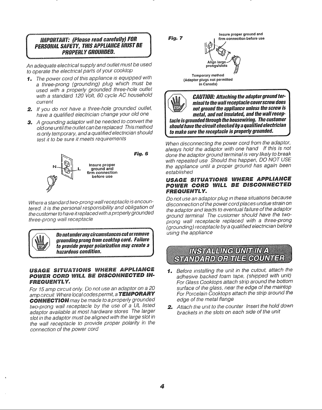
PROP ,t,,OUNO O.
insure proper
ground and
firm connection
before use
Fig. 6
,o.0,-.
groundingprongfromcooktopcord. Failure j
to provideproperpolarization may create a
L. -- hazardouscondition. _)
Fig. 7
Temporary mBthod
(Adaptor plugs not permitted
in Canada)
minalto thewali receptacle coverscrewdoes
CAUTION:Attachingtheadaptorgroundter-
not groundtheapplianceunlessthescrewis
metal,andnotinsulated,andthe wallrecep-
tacleisgroundedthroughthehousewiring.Thecustomer
shouldhavethecircuitcheclcedbya qualifiedelectrician
tomake surethereceptacleis properlygrounded.
When disconnecting the power cord from the adaptor,
always hold the adaptor with one hand ff this is not
done the adaptor ground terminal is very likely to break
with repeated use Should this happen, DO NOT USE
the appliance until a proper ground has again been
established
USAGE SITUATI'IIONS _AfHt_RIE APPL[L_NCE
POWER CORD WHL_. BE DIISCONNECTED
FR[_QUENT'L. Y.
Do not use an adaptor plug In these situations because
disconnection of the power cord ptaces undue strain on
the adaptor-and leads to eventual failure of the adaptor
ground terminal The customer should have the two-
prong wall receptacle replaced with a three-prong
(grounding) receptacle by a qualihed electrician before
using the appliance
Insure proper ground and
_[A_lt_n firm connection before use
large_
prongs/slots _
USAOE SITUAT[ION$ WH[_RE ._PPg.IJANC_
POWER CORD WP_.fLBE DISCONNECTED IN.
FREG_J_N_& Y',
For 15amp circuit only. Do not use an adaptor on a 20
amp circuit. Where local codes permit, a _'_PORARY
CONNeCTiON may be made to a properly grounded
two-prong wall receptacle by the use of a UL listed
adaptor available at most hardware stores The larger"
slot in the adaptor must be aligned with the large slot in
the wall receptacle to provide proper polarity in the
connection of the power cord
_. Before installing the unit in the cutout, attach the
adhesive backed foam tape, (shipped with unit)
For Glass Cooktops attach strip around the bottom
surface of the glass, near the edge of the maintop
For Porcelain Cooktops attach the strip around the
edge of the metal flange
2, Attach the unit to the counter Insert the hold down
brackets in the slots on each side of the unit
4
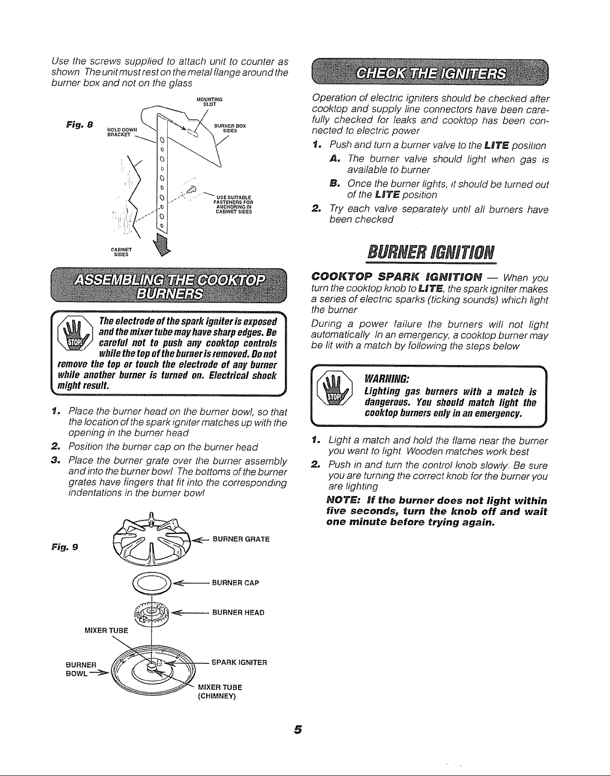
Use the screws supplied to attach unit to counter as
shown The unit must rest on the metal flange around the
burner box and not on the glass
Fig. 8
and themixertubemayhavesharpedges.Be
Theelectrode of the sparkigniter isexposed-"
careful not to push any cooktop controls
whilethe topoftheburnerisremoved.Donot
remove the top or touch the electrode of any burner
while another burner is turned on. Electrical shock
might result,
1. Place the burner head on the burner bowl, so that
the location of thespark igniter matches up with the
opening in the burner head
.2. Position the burner cap on the burner head
3. Place the burner grate over the burner assembly
and into the burner bowl Thebottoms of the burner
grates have fingers that fit into the corresponding
indentations in tt_eburner bowl
Fig. 9
•,_-.-.BURNER GRATE
Operation of electric igniters should be checked after
cooktop and supply fine connectors have been care-
fully checked for leaks and cooktop t_as been corn
nected to electric power
t. Push and turn a burner valve to the LITE position
A. The burner valve should light when gas is
available to burner
B, Once the burner lights, it should be turned out
of the JLITE position
m
Try each valve separately until all burners have
been checked
BURNERIG/VifiOt@
COOKTOP SPARK IGNITBON _ When you
turn the cooktop knob to n-ITE, the spark igniter makes
a series of electric sparks (ticking sounds) which light
the burner
During a power failure the burners will not light
automatically In an emergency a cooktop burner may
be fit with a match by following the steps below
J_ _trlJ Lighting gas burners with a match is
J \_[/ dangerous. You should match light the
L ..........................
Light a match and hold the flame near the burner
you want to light Wooden matches work best
2.
Push in and turn the control knob slowly Be sure
you are turning the correct knob for the burner you
are lighting
NOTE: nf the burner does net light within
five secendsj turn the knob off and wait
one minute before trying again.
cooktopburnersonlyin an emergency
MIXER TUBE
BURNER HEAD
(CHIMNEY)
5
 Loading...