

Kenmore 795.78402.801, 795.78403.801, 795.78412.801, 795.78413.801, 795.78416.801 Service Manual
...
R
REFRIGERATOR
SERVICE MANUAL
CAUTION
BEFORE SERVICING THE PRODUCT
READ THE SAFETY PRECAUTIONS IN THIS MANUAL.
MODELS:
795.78402.801
795.78403.801
795.78406.801
795.78409.801
795.78412.801
795.78413.801
795.78416.801
795.78419.801
Sears, Roebuck and Co., Hoffman Estates, IL60179 U.S.A.
www.sears.com

CONTENTS
SAFETY PRECAUTIONS ...........................................................................................................................................
1. SPECIFICATIONS ..................................................................................................................................................
2. PARTS IDENTIFICATION .......................................................................................................................................
3. DISASSEMBLY ......................................................................................................................................................
3.1 Doors..................................................................................................................................................................
3.2 Leveling and Door Alignment..............................................................................................................................
3.3 Door Gasket........................................................................................................................................................
3.4 Fan and fan motor (evaporator)..........................................................................................................................
3.5 Defrost control assembly.....................................................................................................................................
3.6 Lamp ..................................................................................................................................................................
3.7 Multiduct..............................................................................................................................................................
3.8 Main PCB............................................................................................................................................................
3.9 Dispenser ...........................................................................................................................................................
3.10 Display PWB Replacement .............................................................................................................................
3.11 Funnel Replacement ........................................................................................................................................
3.12 Sub PWB or working dispenser........................................................................................................................
3.13 Duct Door Replacement....................................................................................................................................
3.14 Ice corner door replacement.............................................................................................................................
3.15 Icemaker assembly...........................................................................................................................................
3.16 Auger motor cover ............................................................................................................................................
3.17 How to remove a door ice bin ..........................................................................................................................
3.18 How to insert a door ice bin .............................................................................................................................
3.19 How to remove and reinstall the pull out drawer ..............................................................................................
3.20 Fan and fan motor disassembly method ..........................................................................................................
3.21 Glide out drawer ...............................................................................................................................................
3.22 Cover Valve ......................................................................................................................................................
4. ADJUSTMENT ........................................................................................................................................................
4.1 Compressor .......................................................................................................................................................
4.2 PTC-Starter ........................................................................................................................................................
4.3 OLP (Overload Protector) ..................................................................................................................................
4.4 To remove the cover PTC ..................................................................................................................................
5. CIRCUIT DIAGRAM ...............................................................................................................................................
6. TROUBLESHOOTING ...........................................................................................................................................
6.1 Compressor and electrical components ............................................................................................................
6.2 PTC and OLP ....................................................................................................................................................
6.3 Other electrical components .............................................................................................................................
6.4 Service diagnosis chart .....................................................................................................................................
6.5 Refrigeration cycle ............................................................................................................................................
7. OPERATION PRINCIPLE AND REPAIR METHOD OF ICEMAKER .....................................................................
7.1 Operation principle ............................................................................................................................................
7.2 Ice maker functions ...........................................................................................................................................
7.3 Defect diagnosis function ..................................................................................................................................
8. DESCRIPTION OF FUNCTION & CIRCUIT OF MICOM .......................................................................................
8.1 Function ............................................................................................................................................................
8.2 PCB function .....................................................................................................................................................
8.3 Troubleshooting ................................................................................................................................................
8.4 Main PWB assembly and parts list ...................................................................................................................
9. EXPLODED VIEW AND REPLACEMENT PART LIST ..........................................................................................
2
3
6
7
7
9
10
11
11
12
12
12
13
13
13
13
14
14
14
15
16
16
17
19
19
20
21
21
21
22
22
23
24
24
25
26
27
28
30
30
31
32
33
33
39
44
46
48
SAFETY PRECAUTIONS
Please read the following instructions before servicing your
refrigerator.
1.Check the refrigerator for current leakage.
2.To prevent electric shock,unplug before servicing.
3.Always check line voltage and amperage.
4.Use standard electrical components.
5.Don't touch metal products in the freezer with wet
hands.This may cause frost bite.
6.Prevent water from spiling on to electric elements or the
Machine parts.
7.Before tilting the refrigerator, remove all materials from
on or in the refrigerator.
8.When servicing the evaporator, wear gloves to prevent
injuries from the sharp evaporator fins.
9.Service on the refrigerator should be performed by a
qualified technician.Sealed system repair must be
performed by a CFC certified technician.
- 2 -

1. SPECIFICATIONS
1-1. DISCONNECT POWER CORD BEFORE SERVICING
IMPORTANT: Reconnect all grounding devices.
All parts of this appliance capable of conducting electrical current are grounded. If grounding wires, screws, straps, clips, nuts
or washers used to complete a path to ground are removed for service, they must be returned to their original position and
properly fastened.
1-2. IMPORTANT NOTICE
This information is intended for use by individuals possessing adequate background of electrical, electronic and mechanical
experience.
Any attempt to repair a major appliance may result in personal injury and property damage. The manufacturer or seller cannot
be responsible for the interpretation of this information, nor can it assume any liability in connection with its use.
ELECTRICAL SPECIFICATIONS
1-3.
Freezer temperature control (Middle setting).................................................................
Defrost Control ..............................................................................................................
Defrost Thermostat .......................................................................................................
Electrical Rating : 115VAC, 60Hz...................................................................................
Maximum Current Leakage ...........................................................................................
Maximum Ground Path Resistance ..............................................................................
Energy Consumption......................................................................................................
1-4. NO LOAD PERFORMANCE
Control Position: MID/MID
And Ambient of:
Fresh Food, °F........................................................
Frozen Foor, °F........................................................
Percent Running Time ..............................................
1-5. REFRIGERATION SYSTEM
Minimum Compressor Capacity Vaccum.............................
Minimun Equalized Pressure
@70°F..............................................................
@90°F..............................................................
Refrigerant R134a............................................................
Compressor...............................................................
70°F
33°F to 41°F
-4°F to +4°F
25% - 35%
21 in
49 PSIG
56 PSIG
4.2 oz
957 BTU/hr
Fresh Food, °F......................................................
Frozen Foor, °F.....................................................
Percent Running Time ...........................................
1-6. INSTALLATION
Clearance must be provided at top, sides and rear of the
refrigerator for air circulation.
At Top.................................................................................
At Sides............................................................................
At Rear................................................................................
-6°F to +8°F
Automatic
50°F
1-5 A
0.5mA
0.14 Ohms
22.5 cu.ft. 670kWh/yr
90°F
33°F to 41°F
-4°F to +4°F
45% - 60%
1 in
1/8 in
1 in
- 3 -
1-7. REPLACEMENT PARTS
Relay...........................................................
Overload.....................................................
Defrost Thermostat.....................................
Defrost Heater............................................
Evaporator Fan Motor.................................
Capacitor....................................................
Compressor (Hi-Side).................................
Evaporator (Lo-Side)..................................
Condenser..................................................
Dryer............................................................
Condenser Fan Motor.................................
Temperature Control...................................
Main Control...............................................
Duct Assy Connector..................................
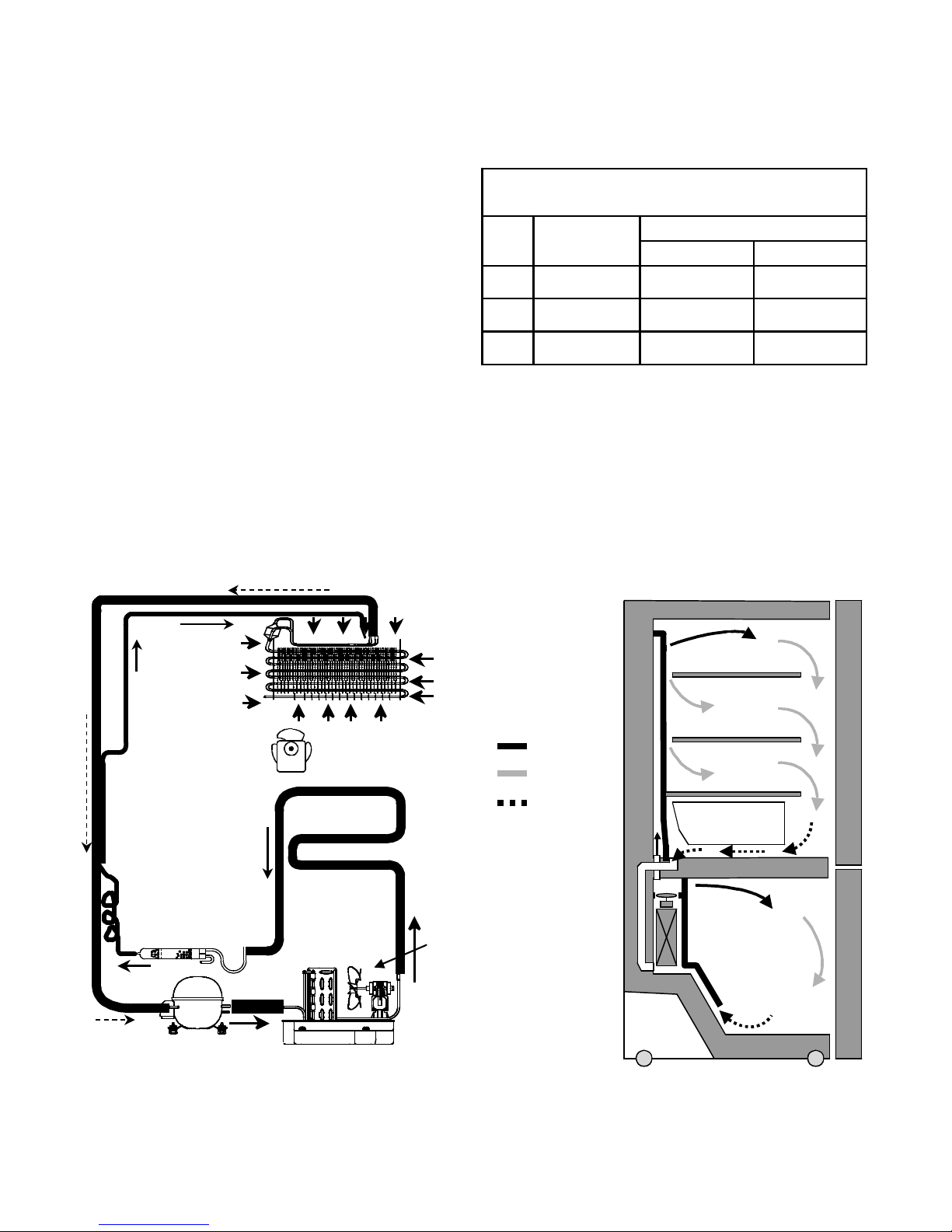
1-8. AIR FLOW
6748C-0004D
6750C-0004R
6615JB2005C
5300JB1100J
4681JK1004E
0CZZJB2012K
TCA31748001
5421JJ1001B
5403JJ1007A
5851JA2002F
4681JB1029J
EBR43358502
EBR41956106
ADJ36834101
PERFORMANCE DATA
(NORMAL OPERATING CONDITIONS)
SYSTEM PRESSURE (PSIG)
AMB WATTS
HIGH SIDE LOW SIDE
70°F 98 (+10 / -10) 98 (+5 / -3) (-5) to (-2)
90°F 98 (+10 / -10) 132 (+3 / -3) (-4) to 1
110°F 103 (+5 / -5) 180 (+5 / -5) (-2) to 3
EVAPORATOR FAN
DRYER
COMPRESSOR
EVAPORATOR
HOT LOOP
CONDENSER
CONDENSER
FAN
COLD AIR
MIXED AIR
AIR RETURN TO
EVAPORATOR
EVAPORATOR
FRESH FOOD
Vegetable box
FREEZER
- 4 -
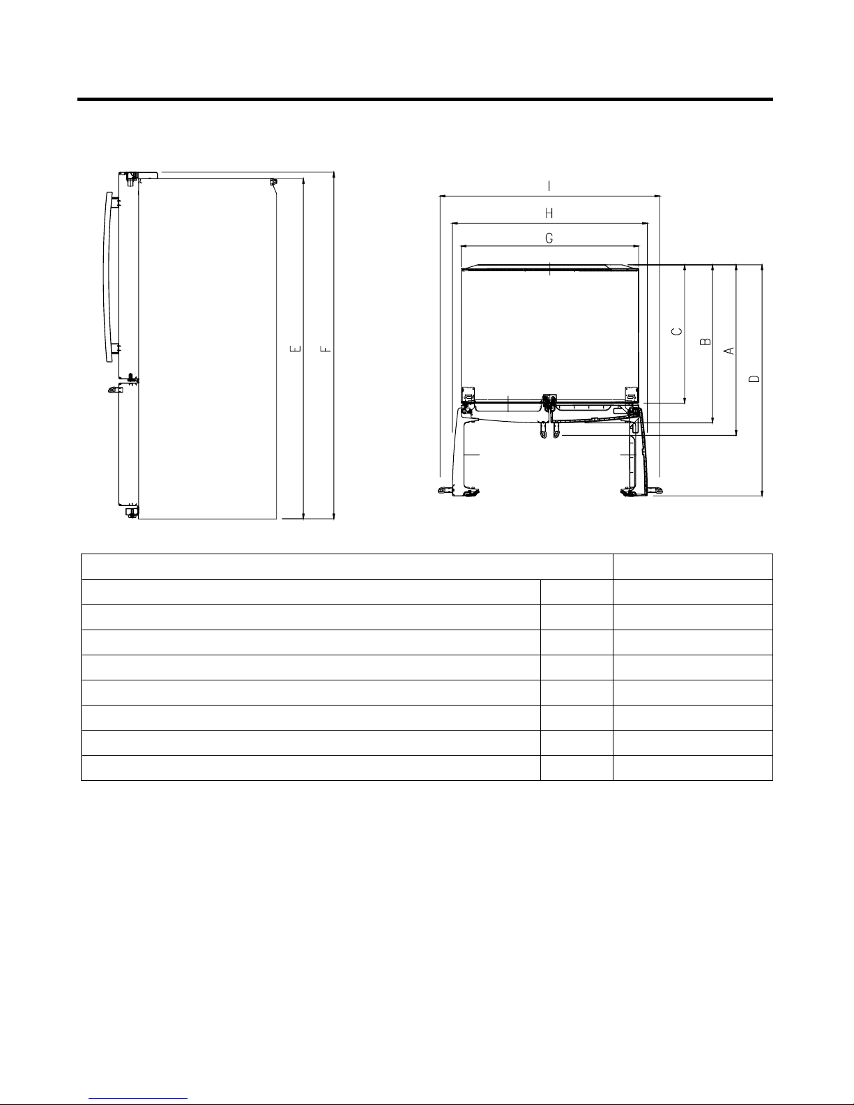
1-8 DIMENSIONS
Description 795.784**
Depth w/ Handles A 34 1/4 in
Depth w/ Handles B 31 3/4 in
Depth w/ o Door C 27 7/8 in
Depth (Total with Door Open) D 46 1/2 in
Height to Top of Case E 68 3/8 in
Height to Top of Door Hinge F 69 3/4 in
Width G 35 3/4 in
Width (door open 90 deg. w/o handle) H 39 1/4 in
- 5 -
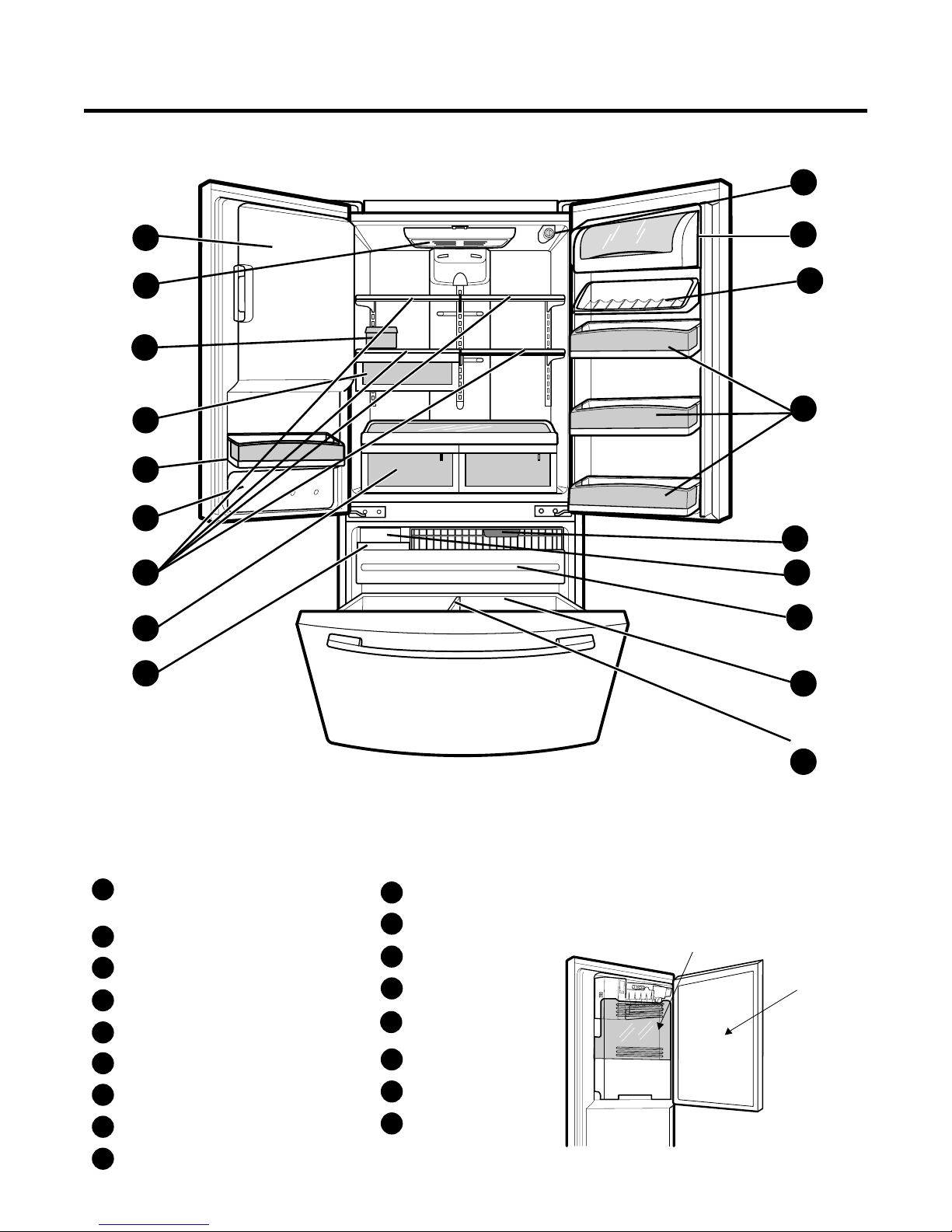
2. PARTS IDENTIFICATION
B
H
A
Q
P
C
O
F
G
N
E
D
C
K
J
I
L
Use this section to become more familiar with the parts and features.
NOTE:This guide covers several different models.The refrigerator you have purchased may have some
or all of the items listed below.The locations of the features shown below may not match your model.
A
Ice Room
(Ice Maker
Refrigerator Light
B
Refrigerator
C
D
E
F
G
H
I
Egg Box
Snack
Water Tank Cover
Turbo Motor
Ice Bin
Filter (Inside)
and Ice Bucket)
Shelves
Pan
Dairy Corner
J
K
Can Rack*
Modular Door Bins
L
M
Crisper
N
Freezer Light
Pull out Drawer
O
Durabase
P
Q
Divider
* On some models
- 6 -
M
Ice Bucket
Ice Room Door
3. DISASSEMBLY
(1)
(2)
(7)
(5)
(6)
(4)
(8)
Figure A
3
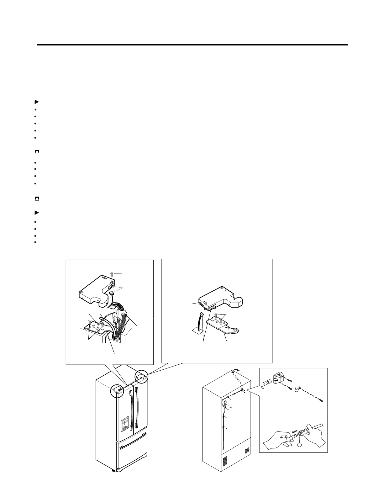
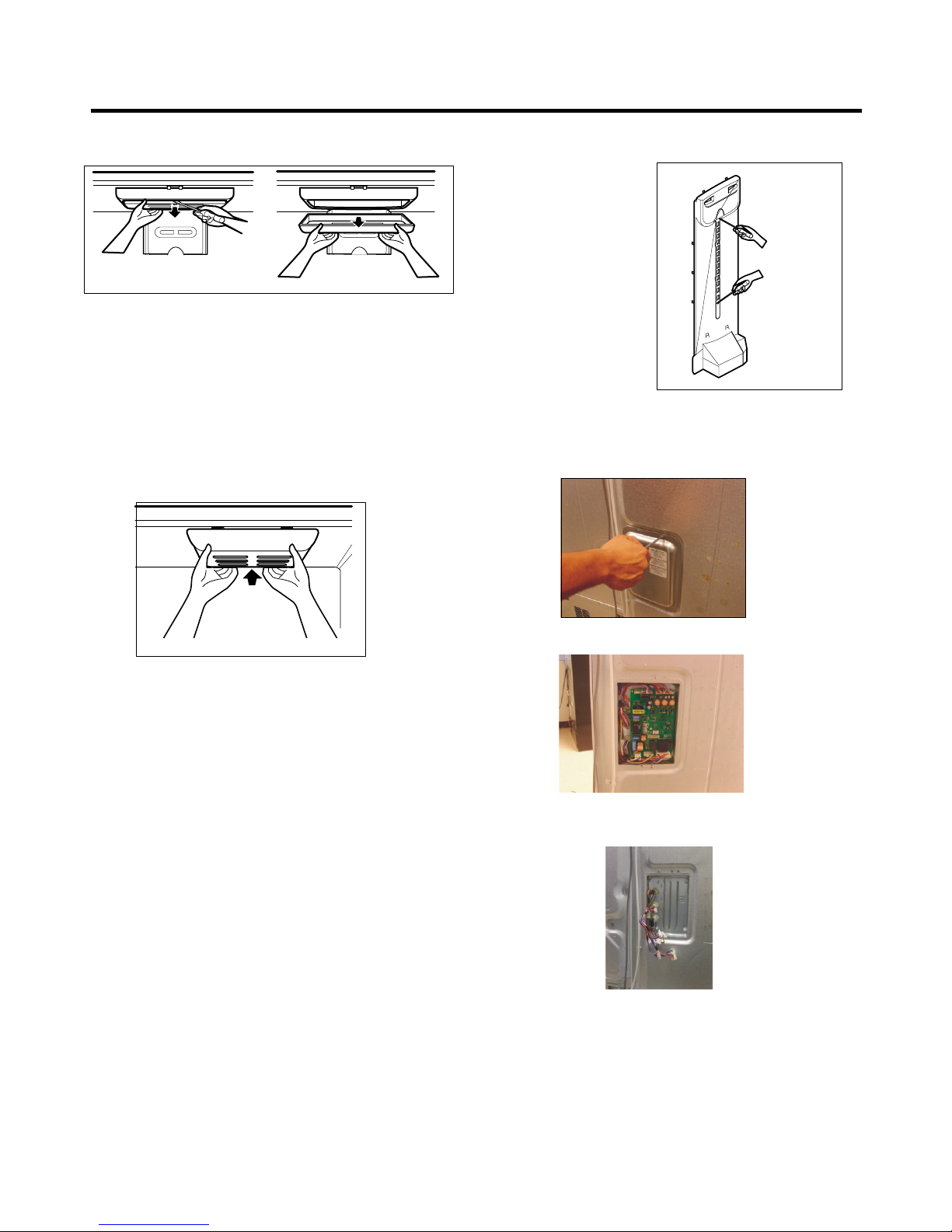
3-1 DOORS
1. Removing Refrigerator Door
NOTE: Handle appearance may vary.
IMPORTANT: Before you begin, turn the refrigerator OFF and unplug it. Remove food and any bins from doors.
Left Door
Loosen the screws and remove the cove on back side (see figure A).
Disconnect water supply tube by pushing back on the disconnect ring (3).
Loosen the cover screw (1).
Disconnect door switch wire (2).
Pull out the tube (4).
CAUTION: If a tube end is deformed or worn out, cut the damaged portion away.
Disconnect wire harness (5).
Remove the ground screw (6).
Loosen screws (7) and lift off the top hinge (8).
Place the door on a non-scratching surface with the inside up.
CAUTION: When removing top hinge, be careful that the door does not fall forward.
Right Door
Loosen the cover screw (1).
Disconnect door switch wire (2).
Loosen screws (7) and lift off the top hinge (8).
Place the door on a non-scratching surface with the inside up.
(1)
- 7 -
(2)
(7)
(8)
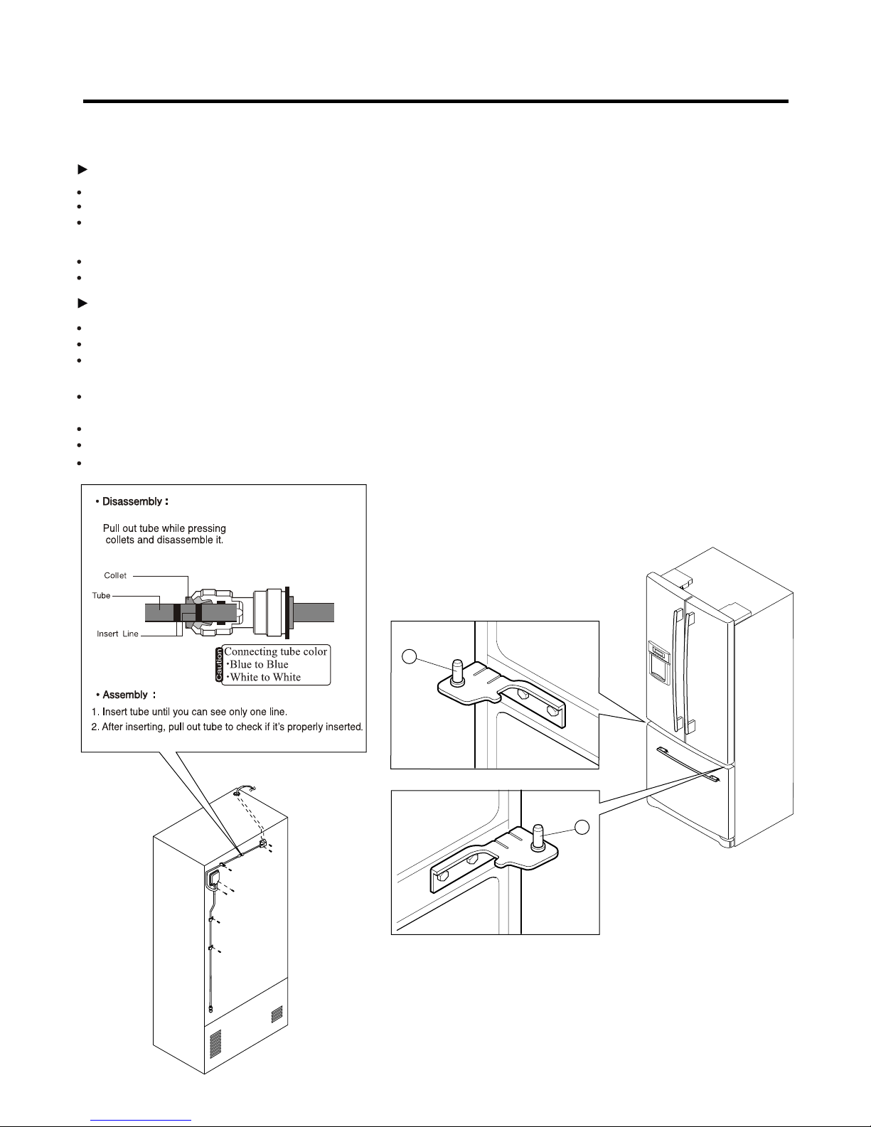
2.Replacing Refrigerator Door
Right Door
Lower the door onto the middle hinge pin (9). Make sure the door is aligned with the cabinet.
Replace the top hinge (8) installing hinge screws (7) to secure it.
Make sure the gasket on the door is flush against the cabinet and is not folded. Support the door on the handle
side while securing hinge. Make sure the door is straight and the gap between the doors is even.
Connect the door switch wire (2).
Tighten the cover screw (1).
Left Door
Lower the door onto the middle hinge pin (10). Make sure the door is aligned with the cabinet.
Replace the top hinge (8) installing hinge screws (7) to secure it.
Make sure the gasket on the door is flush against the cabinet and is not folded. Support the door on the handle
side while tightening. And make sure the door is straight and the gap between the doors is even.
Insert the water supply tube (4) into the connector tube until you see only one scale mark.
(Fully insert the tube over 5/8”(15 mm)).
Install the ground screw (6) and connect the wire harness (5).
Connect the door switch wire (2).
Tighten the cover screw (1).
1.
10
9
- 8 -
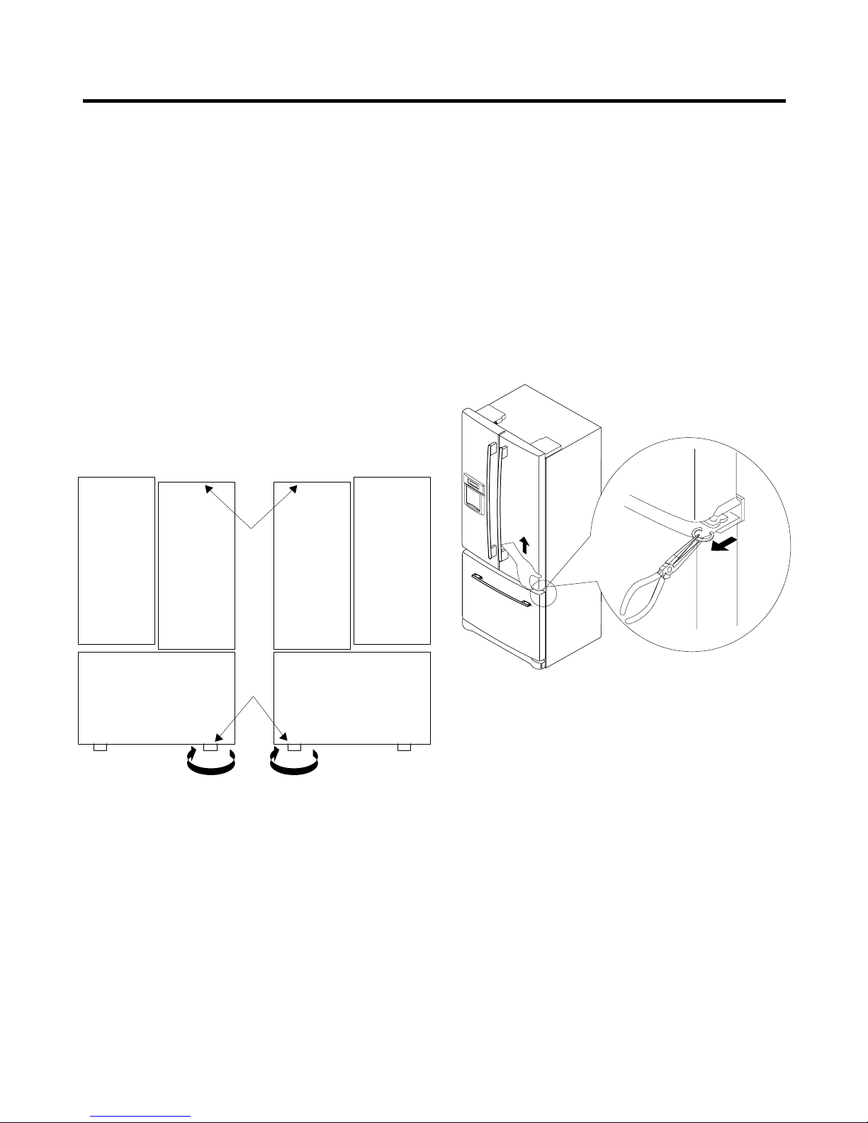
3-2 LEVELING AND DOOR ALIGNMENT
1. Leveling
Your refrigerator has two front leveling screws.
the right and one on the left. If your refrigerator seems
unsteady or you want the doors to close easier, adjust the
Refrigerator’s tilt using the instructions below:
1.Plug the refrigerator’s power cord into a 3-prong
grounded outlet. Move the refrigerator into its final
Position. Remove the base cover.
2.Turn the leveling screw clockwise to raise that side of
the refrigerator or counterclockwise to lower it. It may
take several turns of the leveling screw to adjust the tilt
of the refrigerator.
NOTE:Having someone push against the top of the
refrigerator takes some weight off the leveling screws.
This makes it easier to adjust the screws.
One on
2. Door Alignment
If the space between your doors is uneven, follow the
instructions below to align the doors:
1.With one hand, lift up the door you want to raise at
middle hinge.
2.With other hand, use pliers to insert snap ring as
shown.
3.Insert additional snap rings until the doors are aligned.
(Three snap rings are provided with the refrigerator.)
3.Open both doors again and check to make sure that
they close easily. If not, tilt the refrigerator slightly more
to the rear by turning both leveling screws clockwise. It
may take several more turns, and you should turn both
leveling screws the same amount.
4.Re-adjust if necessary.
5.Replace the base cover.
NOTE:Your new refrigerator is uniquely designed with
two fresh food doors. Either door can be opened or
closed independently of one another. You may have to
exert slight pressure on doors to get them to close
completely.
- 9 -
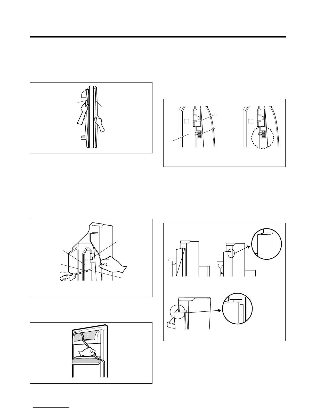
3-3 DOOR GASKET
1. Door Gasket Removal
1. Remove door frame cover
Starting at top of cover and working down, snap cover
out and away from door.
Frame Cover
Handle
2. Door Gasket Replacement
1. Insert gasket bracket clips
1) Insert gasket bracket edge beneath door frame edge.
2) Turn upper gasket bracket spring so that the spring
ends are in the door channel.
3) Push in clip until you hear it snap securely into place.
Gasket
Bracket Clip
Spring
Figure 1
2. Remove gasket bracket clips
There are two clips on each door. Start bracket removal
near one of the middle clips.
1) Pull gasket back to expose gasket bracket clip and
door frame.
2) Insert a flat tip screwdriver into seam between gasket
bracket and door frame and pry back until clips snap
out.
3) Continue prying back along seam until all clips snap
out.
Door
Frame
Flat Tip
Screwdriver
Gasket
Bracket Clip
Gasket
Bracket
Figure 2
Door
Frame
4) Push in remaining clip until you hear it snap securely
into place.
Note: Make sure that no part of gasket bracket edge
protrudes from beneath door frame edge.
2. Insert gasket into channel
1) Snap gasket assembly into the door bracket.
<Inserting the Gasket Assembly into the Bracket Door>
Correct
IncorrectCorrect
Figure 4
3. Remove gasket
Pull gasket free from gasket channel on the three
remaining sides of door.
Figure 3
- 10 -
Incorrect
Figure 5

2) Press gasket into channels on the three remaining
sides of door.
Figure 6
3. Replace door frame cover
Starting at top of cover and working down, snap cover
back into door.
Figure 7
3-4 FAN AND FAN MOTOR(EVAPORATOR)
1. Remove the freezer shelf. (If your refrigerator has an
icemaker, remove the icemaker first)
2. Remove the plastic guide for slides on left side by
unscrewing phillips head screws.
3. Remove the grille by pulling the grille fan forward.
4. Remove the Fan Motor assembly by loosening 2 screws
and disassembling the shroud.
5. Pull out the fan and separate the Fan Motor and Bracket.
* Ice Fan Scroll Assembly Replacement
1) Remove the plastic guide for slides on left side by
unscrewing phillips head screws.
2) Pull the grille forward as shown in the second picture.
3) Disconnect wire harness of the grille
4) Remove the scroll assembly by loosening 3 screws
(1) (2)
(3) (4)
3-5 DEFROST CONTROL ASSEMBLY
Defrost Control assembly consists of Defrost Sensor and
FUSE–M.
The Defrost Sensor works to defrost automatically. It is
attached to the metal side of the Evaporator and senses its
temperature. At 72°C, it turns the Defrost Heater off.
Fuse-M is a safety device for preventing over-heating of
the Heater when defrosting.
1. Pull out the grille assembly. (Figure 12)
2. Separate the connector with the Defrost Control
assembly and replace the Defrost Control assembly
after cutting the Tie Wrap. (Figure 13)
FAN MOTOR
BRACKET
MOTOR
GRILLE
FAN
Figure 11
- 11 -
GRILLE ASSEMBLY
Figure 12
DEFROST-CONTROL
ASSEMBLY
Figure 13
3-6 LAMP
Figure 14
3-6-1 Refrigerator Compartment Lamp
1. Unplug Refrigerator, or disconnect power at the circuit
breaker.
2. If necessary, remove top shelf or shelves.
3. Using a flat instrument, gently pry the cover loose in the
front as shown. Rotate downward to remove rear tabs.4.
Make sure the bulbs are cool to the touch.
Turn bulbs counterclockwise to remove.
5. Assemble in reverse order by snapping the Lamp Cover
in, engaging the rear tabs followed by the front tabs.
(Max. 60 W-2EA)
3-7 MULTI DUCT
1. Remove the upper and
lower Caps by using a flat
screwdriver, and remove
2 screws. (Figure 16)
2. Disconnect the lead wire
on the bottom position.
Figure 16
3-8 MAIN PWB
1) Loosen the 3 screws on the PWB cover.
Figure 15
3-6-2 Freezer Compartment Lamp
1. Unplug refrigerator power cord form outlet.
2. Gently pry the lamp cover loose in the back
as shown. Rotate forward to remove the
front tabs.
3. Make sure the bulb is cool to the touch. Turn the
bulb counterclockwise to remove.
4. Replace with a new 60-watt appliance bulb.
5. Insert tabs on front of cover into slots in freezer
ceiling. Push cover up to snap back into place.
2) Remove the PWB cover
3) Disconnect wire harness and replace the main PWB in
the reverse order of removal.
- 12 -
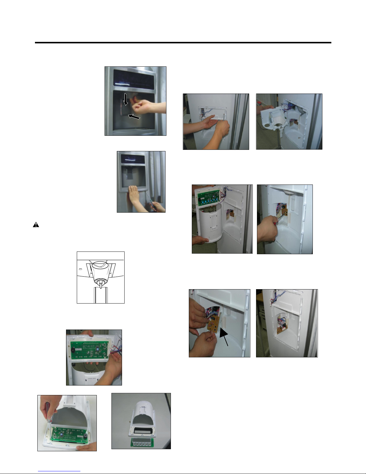
3-9 DISPENSER
3-11 FUNNEL REPLACEMENT
1) Disconnect funnel and
button assembly by
pulling down and
forward.
2) Remove display frame
assembly by making a gap
between a display frame
assembly and door with a
flat blade screwdriver and
pulling it forward. The cover
dispenser is attached with a
hook.
CAUTION: When replacing the dispenser cover in the
reverse order of removal, be careful that the lead wire
does not come out and the water tube is not pinched by
the dispenser cover, as shown in the picture below.
1) Pull up and out on the dispenser cover to remove.
2) Disconnect the wire harness.
3) Replace in reverse order.
3-12 SUB PWB FOR WORKING DISPENSER
1) Loosen the screw on the sub PWB.
3-10 DISPLAY PWB REPLACEMENT
1) Pull up and out on the dispenser cover to remove.
2) Follow the steps in the pictures
2) Pull the sub PWB down.
3) Disconnect the wire harness and replace the sub PWB
in the reverse order of removal.
- 13 -
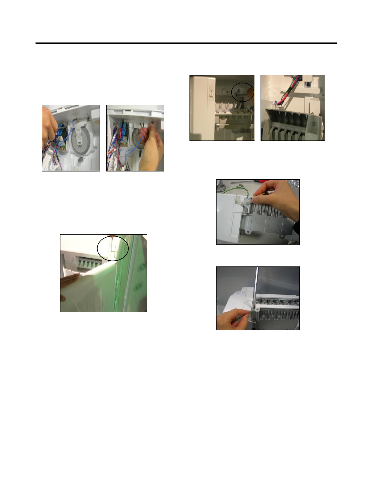
3-13 DUCT DOOR REPLACEMENT
1) Pull up and out on the dispenser cover to remove.
2) Disconnect the wire harness.
3) Remove the funnel
4) Replace in reverse order.
3-14 ICE CORNER DOOR REPLACEMENT
1) Loosen the front screw as shown in the picture.
2) Lift up the hinge with one hand.
3) Pull out the Ice Corner Door with the other hand.
3-15 ICEMAKER ASSEMBLY
1) Loosen two screws as shown in the first picture.
2) Disconnect the wire harness & ground screw replace
theIcemaker assembly in the reverse order of removal.
Hinge
3) It separates a ground connection screw.
- 14 -
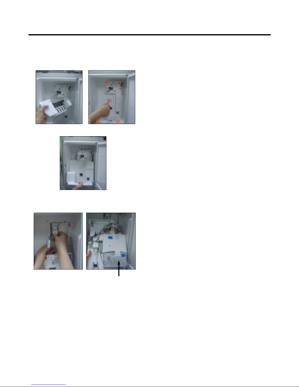
3-16 AUGER MOTOR COVER
1) After removing the icemaker remove the (5) stainless
screws holding the auger motor cover, shown in the
picutres below.
2) Grip the bottom of motor cover assembly and pull out it.
3) Disconnect wire harness of motor cover assembly.
There is a auger motor on the back, as shown in the
picture.
Auger Motor
- 15 -
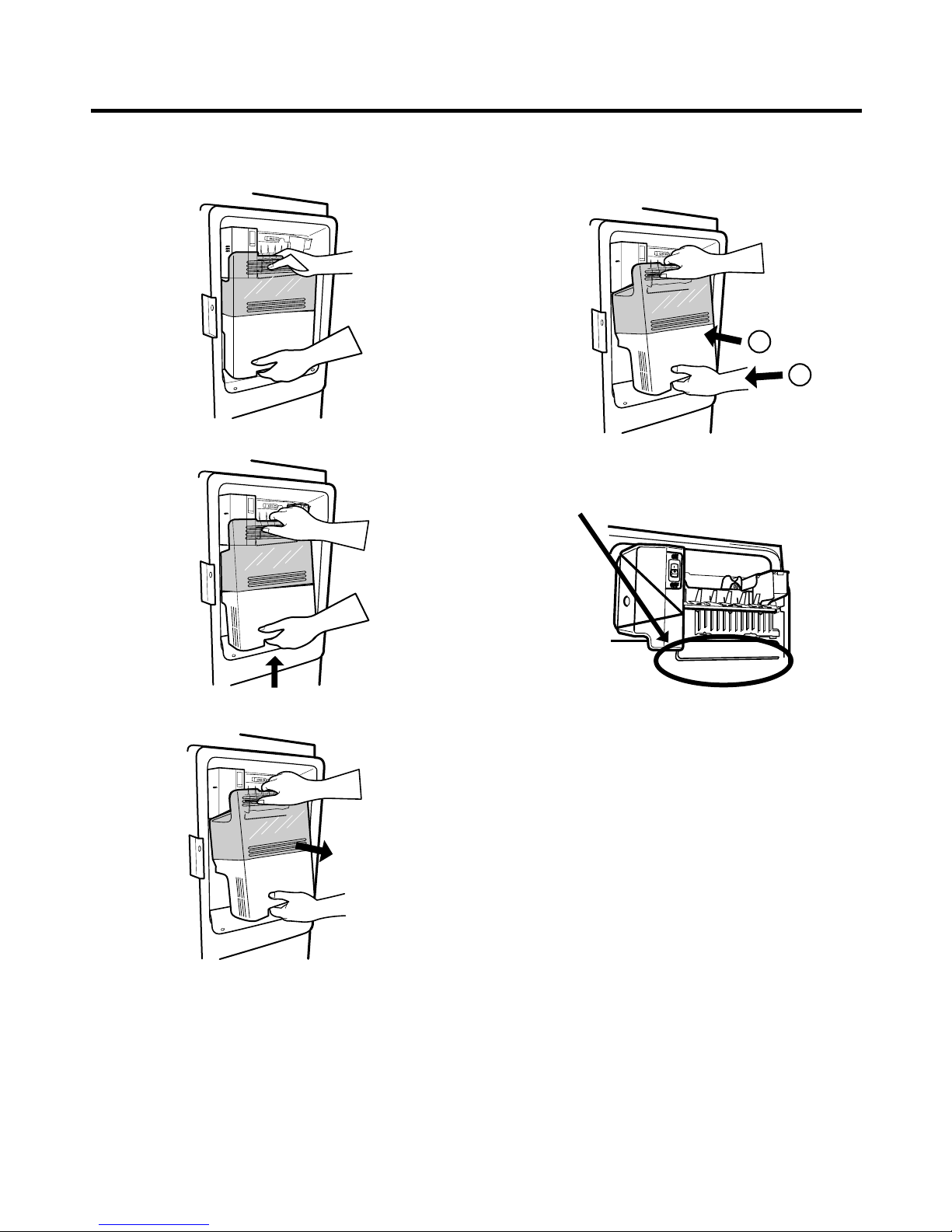
3-17 HOW TO REMOVE A DOOR ICE BIN
1) Grip the handles, as shown in the picture.
2) Lift the lower part slightly.
3-18 HOW TO INSERT A DOOR ICE BIN
1) Insert the Ice Bin, slightly tilting it to avoid touching the
Icemaker. (especially, ice maker lever)
1
2
Insert the ice bucket carefully avoid contacing the
automatic shut off arm.
3) Take the Ice Bin out slowly.
- 16 -
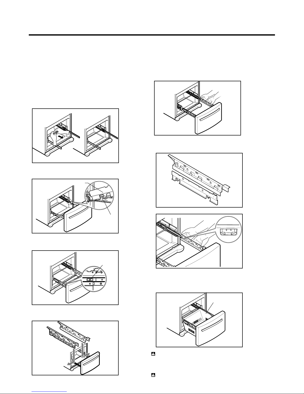
3-19 PULL OUT DRAWER
1. HOW TO INSTALL PULL OUT DRAWER
IMPORTANT: To avoid possible injury, product or
property damage, you will need two people to perform
the following instructions.
• With both hands, hold the center of the bar and pull it
out to let both rails out to full extension simultaneously.
Fig. 38
• Hook door supports into rail tabs.
Fig. 39
Door Supports
• Align the top holes of the rail cover with the top holes of
the door supports to assemble the rail cover.
Fig. 42
•
Verify the hole’s assembly
Fig. 43
Rail tabes
• Lower door into final position and tighten the screws.
Fig. 40
Screws
•
Make sure you have a right rail cover for each side.
Right
Rail cover
Left
Rail cover
Fig. 41
Fig. 44
• With the rails pulled out to full extension, insert the
durabase in the rail assembly.
Fig. 45
Durabase
WARNING: To prevent accidental child and pet
entrapment or suffocation risk. DO NOT allow them to
play inside of drawer.
WARNING: DO NOT step or sit down on Freezer Door.
- 17 -
 Loading...