

Kenmore 795.7620, 795.6827, 795.7827 Service Manual

BOTTOM FREEZER REFRIGERATOR
REFRIGERATOR
SERVICE MANUAL
CAUTION
BEFORE SERVICING THE PRODUCT
READ THE SAFETY PRECAUTIONS IN THIS MANUAL.
Sears Brands Management Corporation, Hoffman Estates, IL 60179 U.S.A.
MODELS:
795.7620
795.6827
795.7827
color number
www.sears.com

CONTENTS
SAFETY PRECAUTIONS ........................................................................................................
1. SPECIFICATIONS ...............................................................................................................
2. PARTS IDENTIFICATION ....................................................................................................
2-1 Freezer Drawer Model.....................................................................................................
2-2 Freezer Swing Model.......................................................................................................
3. DISASSEMBLY ...................................................................................................................
3-1 Fan and Fan Motor..........................................................................................................
3-2 Defrost Control Assembly.................................................................................................
3-3 Lamp................................................................................................................................
3-4 Control Box Refrigerator..................................................................................................
3-5 Multiduct..........................................................................................................................
3-6 Cover Valve......................................................................................................................
3-7 Door Disassembly for Drawer Type Models.....................................................................
3-7-1 Remove Drawer Refrigerator Door.........................................................................
3-7-2 Replace Drawer Refrigerator Door.........................................................................
3-7-3 Reverse Drawer Refrigerator Door.........................................................................
3-7-4 Pull out Drawer.......................................................................................................
3-7-5 How to Reverse Drawer Door Handle....................................................................
3-8 Door Disassembly for Swing Type Models......................................................................
3-8-1 Remove Swing Refrigerator and Freezer Doors....................................................
3-8-2 Replace Swing Refrigerator and Freezer Doors.....................................................
3-8-3 Reverse Swing Refrigerator and Freezer Doors....................................................
3-8-4 How to Reverse Swing Door Handle......................................................................
3-9 After completing the job...................................................................................................
3-10 Leveling and door closing..............................................................................................
3-11 Door alignment...............................................................................................................
4. ADJUSTMENT ....................................................................................................................
4-1 Compressor ...................................................................................................................
4-2 PTC-Starter ....................................................................................................................
4-3 OLP (overload protector) ...............................................................................................
5. CIRCUIT DIAGRAM ............................................................................................................
5-1 For Drawer Type Models..................................................................................................
5-2 For Swing Type Models...................................................................................................
6. TROUBLESHOOTING ........................................................................................................
6-1 Compressor and electric components ...........................................................................
6-2 PTC and OLP .................................................................................................................
6-3 Other electrical components ..........................................................................................
6-4 Service diagnosis chart ..................................................................................................
6-5 Refrigeration cycle .........................................................................................................
3
4
6
6
7
8
8
8
8
9
9
10
11
11
11
12
14
16
17
17
18
19
23
24
24
24
25
25
25
26
27
27
28
29
29
30
31
32
33
- 2 -

7. OPERATION PRINCIPLE AND REPAIR METHOD OF ICEMAKER ..................................
7.1 Operation principle .........................................................................................................
7.2 Ice maker functions ........................................................................................................
8. CIRCUIT OF MICOM (DRAWER TYPE MODELS)..............................................................
8.1 Function .........................................................................................................................
8.2 PCB function ..................................................................................................................
8.3 Resistance specification of sensor .................................................................................
9. CIRCUIT OF MICOM (SWING TYPE MODELS)..................................................................
9.1 Function .........................................................................................................................
9.2 PCB function ..................................................................................................................
9.3 Resistance specification of sensor .................................................................................
10. EXPLODED VIEW AND REPLACEMENT PART LIST......................................................
35
36
38
39
39
43
47
48
48
52
56
57
SAFETY PRECAUTIONS
Please read the following instructions before
servicing your refrigerator.
1.Check the refrigerator for current leakage.
2.To prevent electric shock,unplug before
servicing.
3.Always check line voltage and amperage.
4.Use standard electrical components.
5.Don't touch metal products in the freezer
with wet hands.This may cause frost bite.
6.Prevent water from spiling on to electric
elements or the machine parts.
7.Before tilting the refrigerator, remove all
materials from on or in the refrigerator.
8.When servicing the evaporator, wear gloves
to prevent injuries from the sharp evaporator
fins.
9.Service on the refrigerator should be
performed by a qualified technician.Sealed
system repair must be performed by a CFC
certified technician.
- 3 -

1. SPECIFICATIONS
1-1. DISCONNECT POWER CORD BEFORE SERVICING
IMPORTANT: Reconnect all grounding devices.
All parts of this appliance capable of conducting electrical current are grounded. If grounding wires, screws, straps, clips, nuts
or washers used to complete a path to ground are removed for service, they must be returned to their original position and
properly fastened.
1-2. IMPORTANT NOTICE
This information is intended for use by individuals possessing adequate background of electrical, electronic and mechanical
experience.
Any attempt to repair a major appliance may result in personal injury and property damage. The manufacturer or seller cannot
be responsible for the interpretation of this information, nor can it assume any liability in connection with its use.
ELECTRICAL SPECIFICATIONS
1-3.
Freezer temperature control (Middle setting)
Defrost Control ..............................................................................................................
Defrost Thermostat .......................................................................................................
Electrical Rating : 115VAC, 60Hz...................................................................................
Maximum Current Leakage ...........................................................................................
Maximum Ground Path Resistance ..............................................................................
Energy Consumption......................................................................................................
.................................................................
1-4. NO LOAD PERFORMANCE
Control Position: MID/MID
And Ambient of:
Fresh Food, °F........................................................
Frozen Foor, °F........................................................
Percent Running Time ..............................................
1-5. REFRIGERATION SYSTEM
Minimum Compressor Capacity Vaccum.............................
Minimun Equalized Pressure
@70°F..............................................................
@90°F..............................................................
Refrigerant R134a............................................................
Compressor...............................................................
70°F
33°F to 41°F
-4°F to +4°F
25% - 35%
21 in
49 PSIG
56 PSIG
4.2 oz
740 BTU/hr
Fresh Food, °F......................................................
Frozen Foor, °F.....................................................
Percent Running Time ...........................................
1-6. INSTALLATION
Clearance must be provided at top, sides and rear of the
refrigerator for air circulation.
At Top.................................................................................
At Sides..............................................................................
At Rear...............................................................................
-6°F to +8°F
Automatic
46.4°F
1-5 A
0.5mA
0.14 Ohms
465kWh/yr (Energy Star)
90°F
33°F to 41°F
-4°F to +4°F
45% - 60%
2 in
2 in
2 in
- 4 -
1-7. REPLACEMENT PARTS
Relay...........................................................
Overload.....................................................
Defrost Thermostat.....................................
Defrost Heater............................................
Evaporator Fan Motor.................................
Capacitor....................................................
Compressor (Hi-Side).................................
Evaporator (Lo-Side)..................................
Condenser..................................................
Dryer............................................................
Condenser Fan Motor.................................
Temperature Control...................................
Main Control (For Drawer Type Models).....
Main Control (For Swing Type Models).......
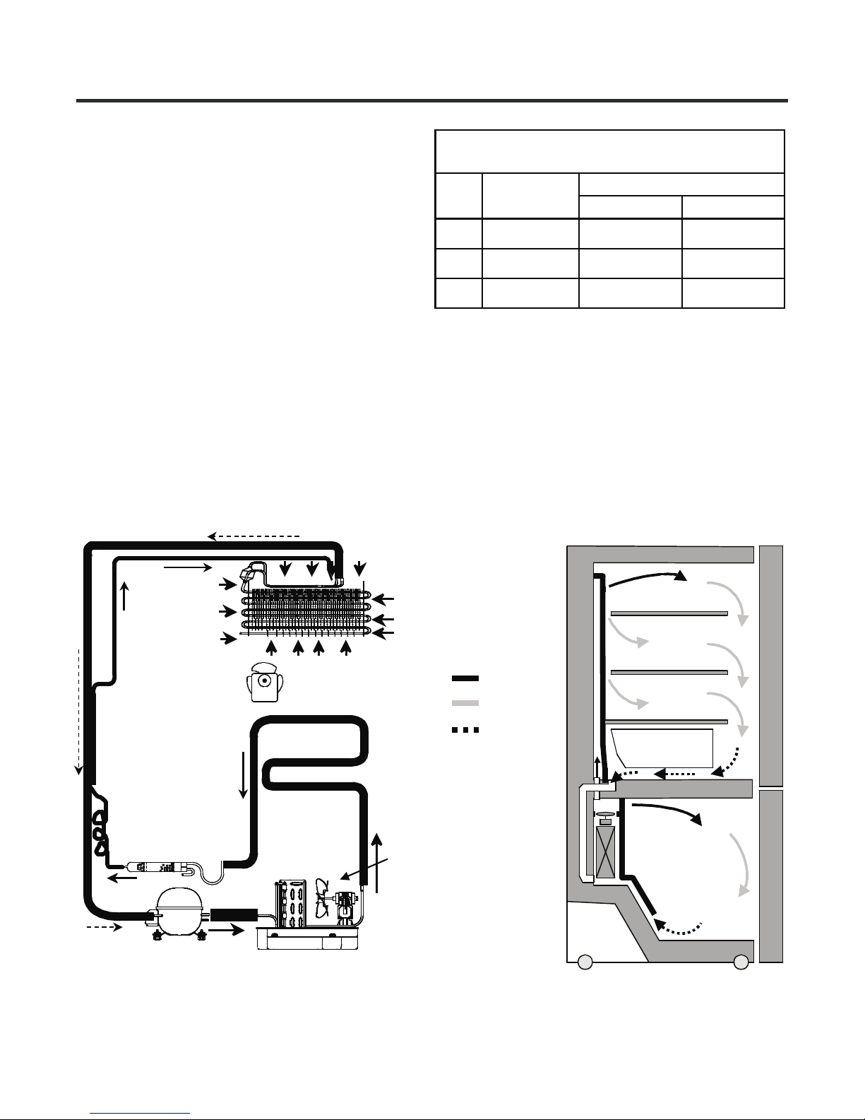
1-8. AIR FLOW
EBG32606502
6750C-0005P
6930JK2001B
5300JB1100J
4681JB1027N
0CZZJB2012J
TCA32196201
5421JJ1001B
5403JJ1007A
5851JA2007E
4681JB1027P
6500JB1001M
EBR64110501
EBR64110502
PERFORMANCE DATA
(NORMAL OPERATING CONDITIONS)
SYSTEM PRESSURE (PSIG)
AMB WATTS
HIGH SIDE LOW SIDE
70°F 98 (+10 / -10) 98 (+5 / -3) (-5) to (-2)
90°F 98 (+10 / -10) 130 (+3 / -3) (-4) to 1
110°F 103 (+5 / -5) 174 (+5 / -5) (-2) to 3
EVAPORATOR FAN
DRYER
COMPRESSOR
EVAPORATOR
HOT LOOP
CONDENSER
CONDENSER
FAN
COLD AIR
MIXED AIR
AIR RETURN TO
EVAPORATOR
EVAPORATOR
FRESH FOOD
Vegetable box
FREEZER
- 5 -
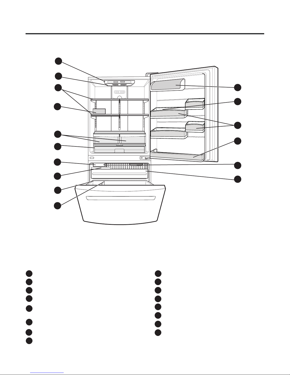
2. PARTS IDENTIFICATION
2-1 FREEZER DRAWER MODEL
A
B
D
G
H
J
C
E
F
K
L
M
N
O
P
I
Use this section to become more familiar with the parts and features.
NOTE: This guide covers several different models. The refrigerator you have purchased may have some
or all of the items listed below. The locations of the features shown below may not match your model.
A
Digital Sensor Control
B
Refrigerator Light
C
Shelves
D
Egg Box
Optibin Crispers
E
Keeps fruits and vegetable fresh and crisp
Pantry
F
G
Icemaker*
H
Ice Bin
I
Durabase
J
- 6 -
Divider
K
Dairy Bin
L
Bottle Guide
M
Door Bins
N
Refrigerator Door Rack
Freezer Light
O
Pull out Drawer
P
*on some models
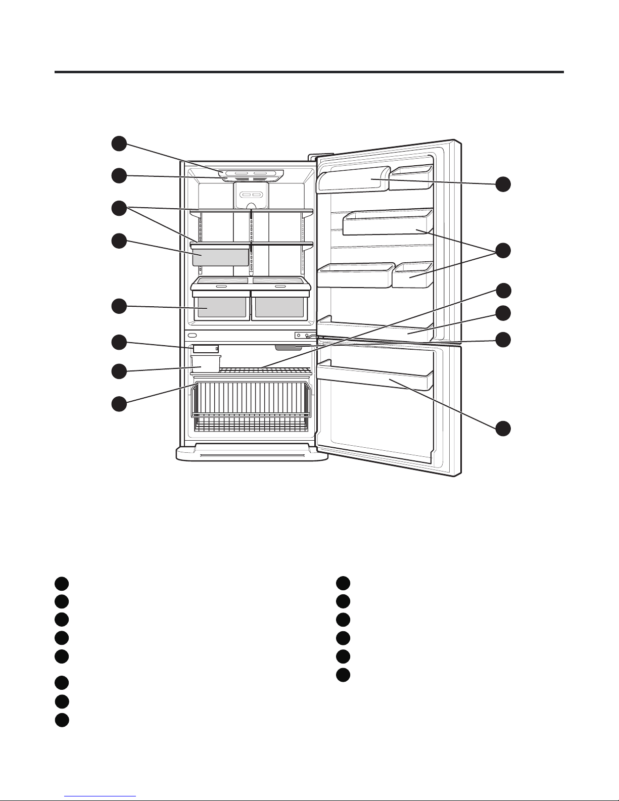
2-2 FREEZER SWING MODEL
A
B
C
D
E
F
G
H
I
J
K
L
M
N
Use this section to become more familiar with the parts and features.
NOTE: This guide covers several different models. The refrigerator you have purchased may have some
or all of the items listed below. The locations of the features shown below may not match your model.
Digital Sensor Control
A
B
Refrigerator Light
C
Shelves
D
Snack Pan
E
Optibin Crisper
Keeps fruits and vegetable fresh and crisp
F
Icemaker
G
Ice Bin
H
Wire Durabase
- 7 -
I
Dairy Bin
J
Door Bins
K
Wire Freezer Shelf
L
Refrigerator Door Rack
Freezer Light
M
Freezer Door Rack
N
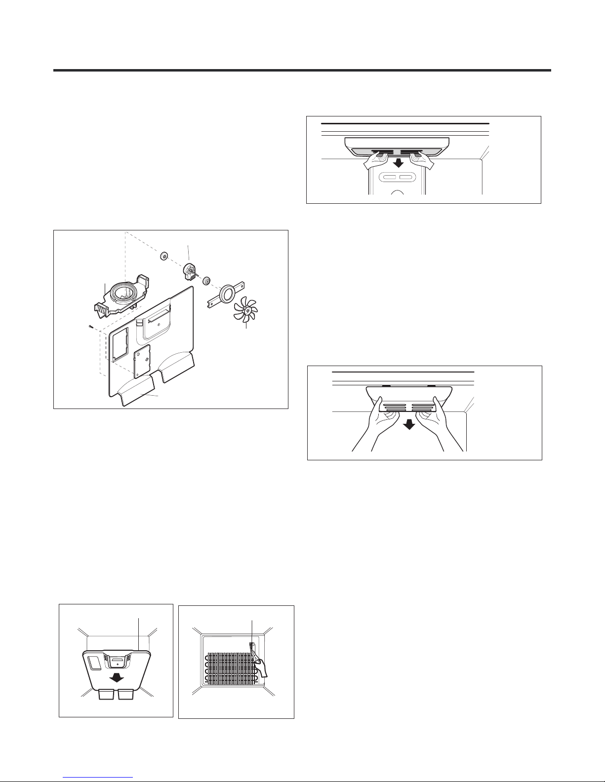
3. DISASSEMBLY
3-1 FAN AND FAN MOTOR
1. Remove the freezer shelf. (If your refrigerator has an
icemaker, remove the icemaker first).
2. Remove the plastic guide for slides on left side by
unscrewing phillips head screws.
3. Remove the grille by removing one screw and pulling the
grille forward.
4. Remove the Fan Motor assembly by loosening 2 screw and
disassemble the shroud.
5. Pull out the fan and separate the Fan Motor and Bracket.
FAN MOTOR
BRACKET
MOTOR
FAN
3-3 LAMP
Fig. 4
3-3-1 REFRIGERATOR COMPARTMENT LAMP
1. Unplug the power cord from the outlet.
2. Remove Refrigerator shelves.
3. Release the hooks on both ends of the lamp shield and pull
the shield downward to remove it.
4. Turn the lamp counterclockwise.
5. Assemble in reverse order of disassembly.
6. Replacement bulb must be the same specification as the
original (Max. 60 W-2EA).
GRILLE
Fig. 1
3-2 DEFROST CONTROL ASSEMBLY
Defrost Control assembly consist of Drefrost Sensor and
FUSE-M.
The Defrost Sensor works to defrost automatically. It is
attached to the metal side of the Evaporator and senses its
temperature.
Fuse-M is safety device for preventing over-heating of the
Heater when defrosting.
At 72°C, it turns the Defrost Heater off.
1. Pull out the grille assembly. (Figure 2)
2. Separate the connector with the Defrost Control assembly
and replace the Defrost Control assembly after cutting the Tie
Wrap. (Figure 3)
GRILLE ASSEMBLY
DEFROST-CONTROL
ASSEMBLY
Fig. 5
3-3-2 FREEZER COMPARTMENT LAMP
1. Unplug refrigerator or disconnect power.
2. Reach behind light to remove bulb.
3. Replace bulb with a 60W appliance bulb.
4. Plug in refrigerator or reconnect power.
Fig. 2
Fig. 3
- 8 -
3-4 CONTROL BOX-REFRIGERATOR
1. First, remove all shelves in the refrigerator, than remove the Refrigerator control Box by loosening 2 screws.
CONTROL BOX
COVER LAMP
2. Remove the Refrigerator Control Box by pulling it downward.
3. Disconnect the lead wire on the right position and separate the lamp sockets.
Fig. 6
3-5 MULTI DUCT
1. Remove an upper and lower Cap by using a flat screwdriver, and loosen 2 screws. (Figure 7,8)
2. Disconnect the lead wire on the botton position.
For Drawer Type Models
For Swing Type Models
Fig. 7
Fig. 8
- 9 -
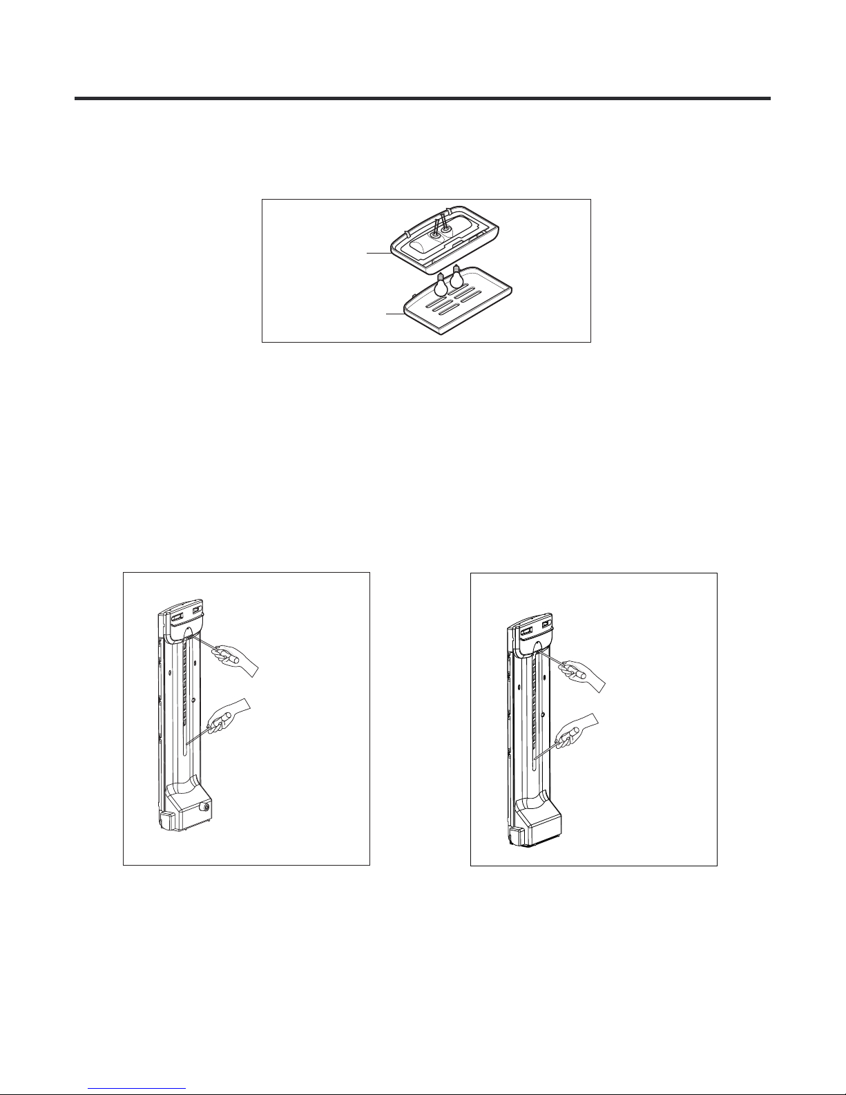
3-6 COVER VALVE
3-6-1 DISASSEMBLE
1. Push to inside the cover valve.
2. Push to the right and release.
Fig. 9
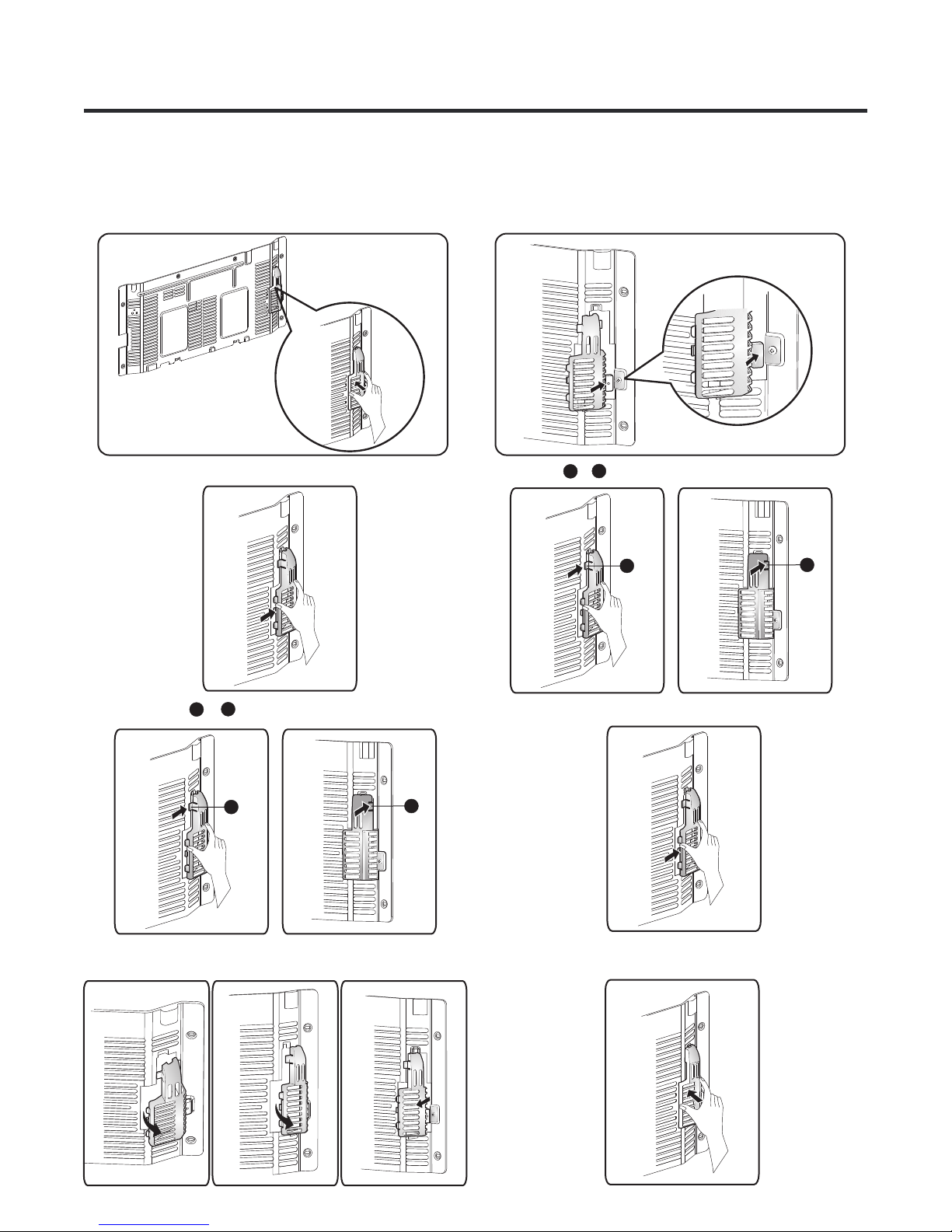
3-6-2 ASSEMBLE
1. Insert the cover valve as shown in the picture, push to insert
(may need force).
Fig. 16
a
2. Insert hook &
b
a
b
Fig. 10
a
3. Release hook &
4. Turn the cover valve 120° as shown in the picture,
then release it.
b
a
Fig. 11 Fig. 12
Fig. 17
3. Push to the right to insert the cover valve.
b
Fig. 19
4. Then push to inside to assembly.
Fig. 18
Fig. 14Fig. 13 Fig. 15
Fig. 20
- 10 -
3-7 DOOR DISASSEMBLY
FOR DRAWER TYPE MODELS
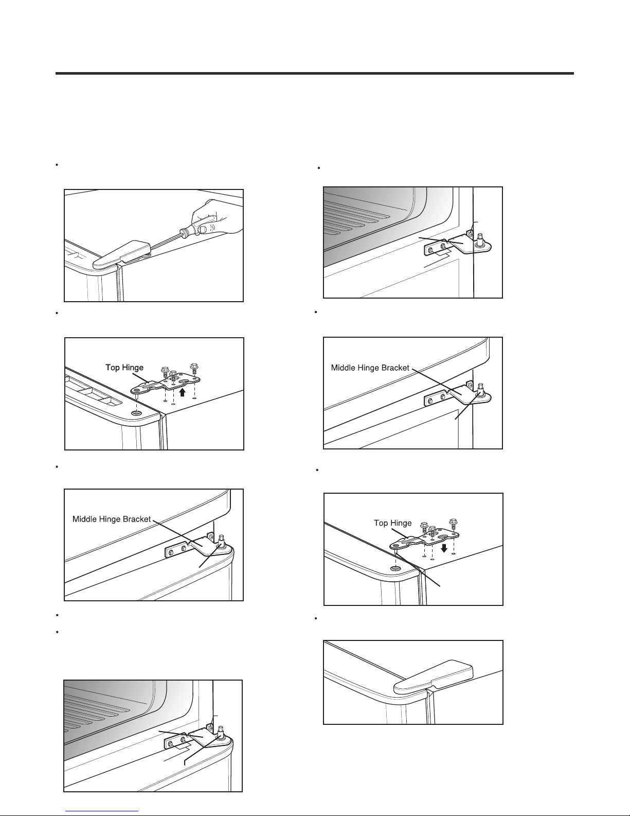
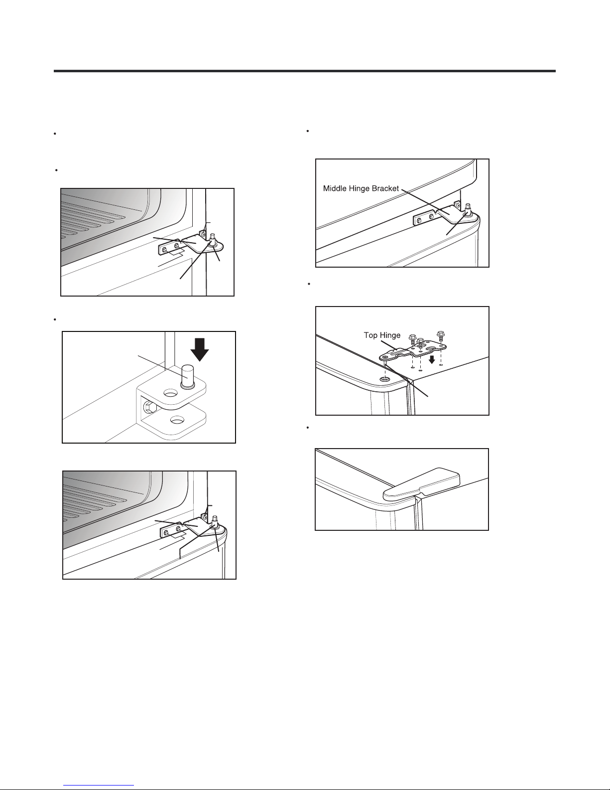
3-7-1 REMOVE DRAWER
REFRIGERATOR DOOR
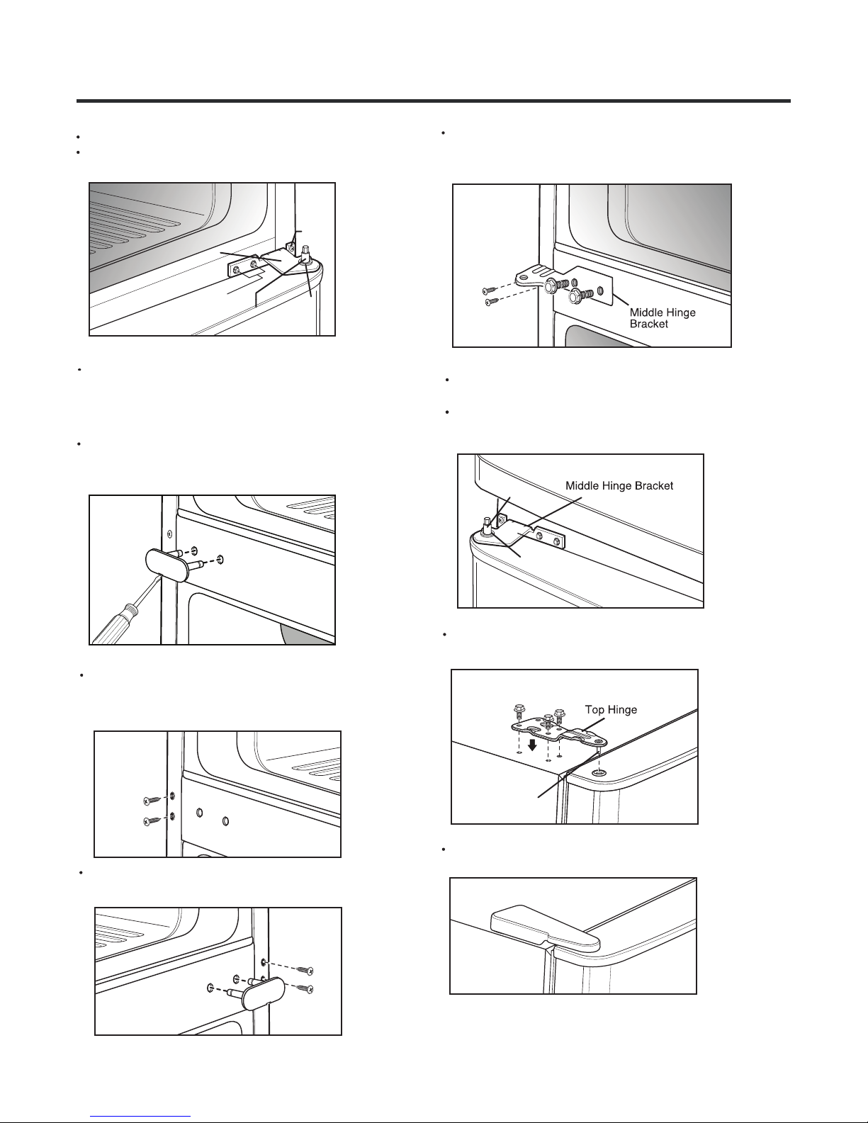
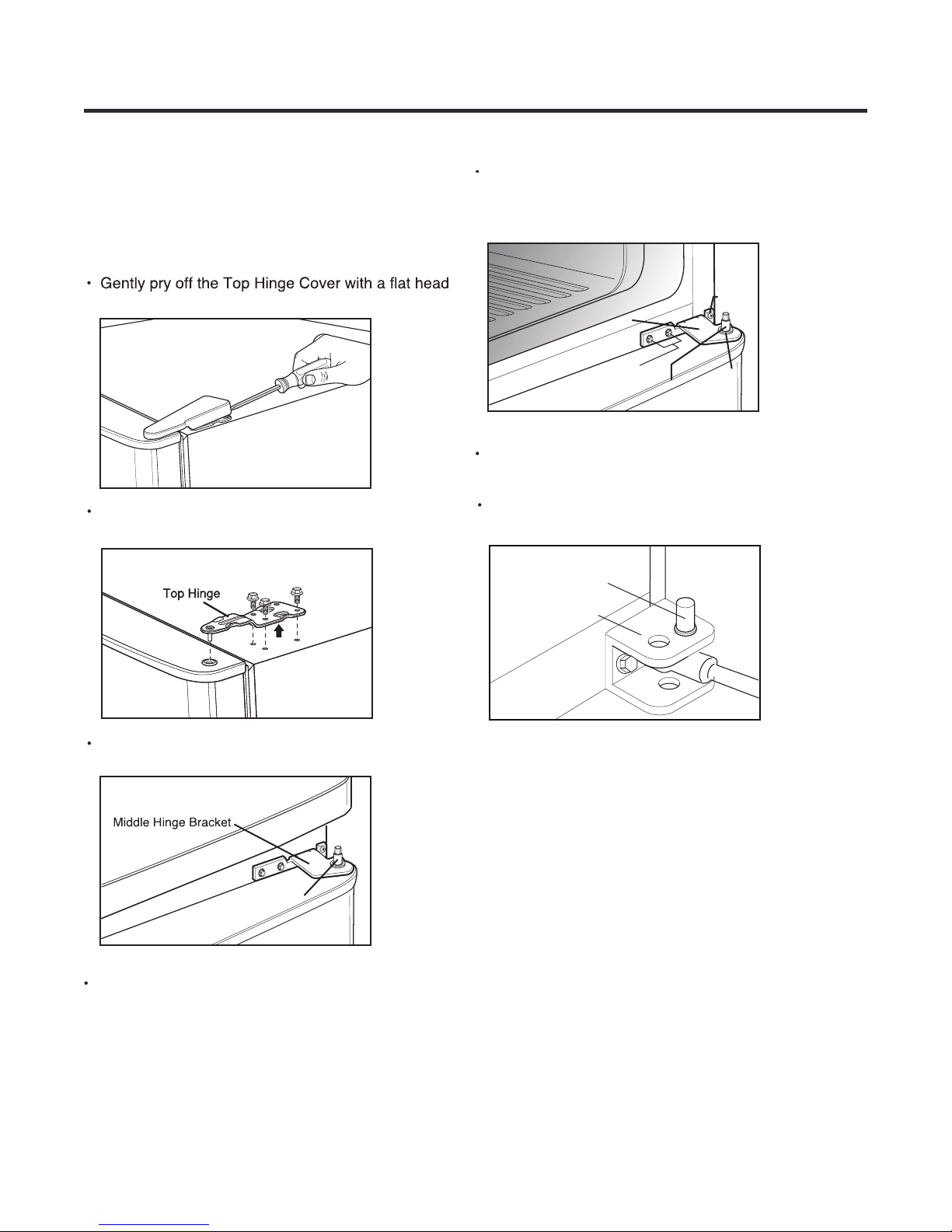
Gently pry off Top Hinge Cover with a flat head
screwdriver and remove.
Fig. 21
Using 10mm or 13/32-inch socket wrench, remove
the 3 bolts and lift off the Top Hinge. Set parts aside.
Fig. 22
3-7-2 REPLACE DRAWER
REFRIGERATOR DOOR
Reattach Middle Hinge Bracket with the previously
removed 2 bolts and 2 screws.
Fig. 21
Screws Screws
Middle Hinge
Bracket
Bolts
Fig. 25
Put refrigerator door down over the Hinge
Pin on the Middle Hinge Pin Bracket.
Fig. 26
Hinge Pin
(2) (2)
Lift up door slightly and remove it. Place door on
a non scratching surface.
Fig. 23
Hinge Pin
Remove washer and set aside.
Use a 10mm or 13/32 inch socket wrench to remove
the 2 bolts in Middle Hinge Bracket. Remove
screws. Set Middle Hinge Bracket and other parts
aside.
Fig. 21
Middle Hinge
Bracket
Bolts
Fig. 24
Middle Hinge
Line up Top Hinge with holes in top of
refrigerator. Use the 3 bolts to replace the Hinge.
Fig. 27
Top Hinge Pin
Tighten Bolts. Force-fit Top Hinge Cover over top
Hinge.
Fig. 28
Screw
- 11 -
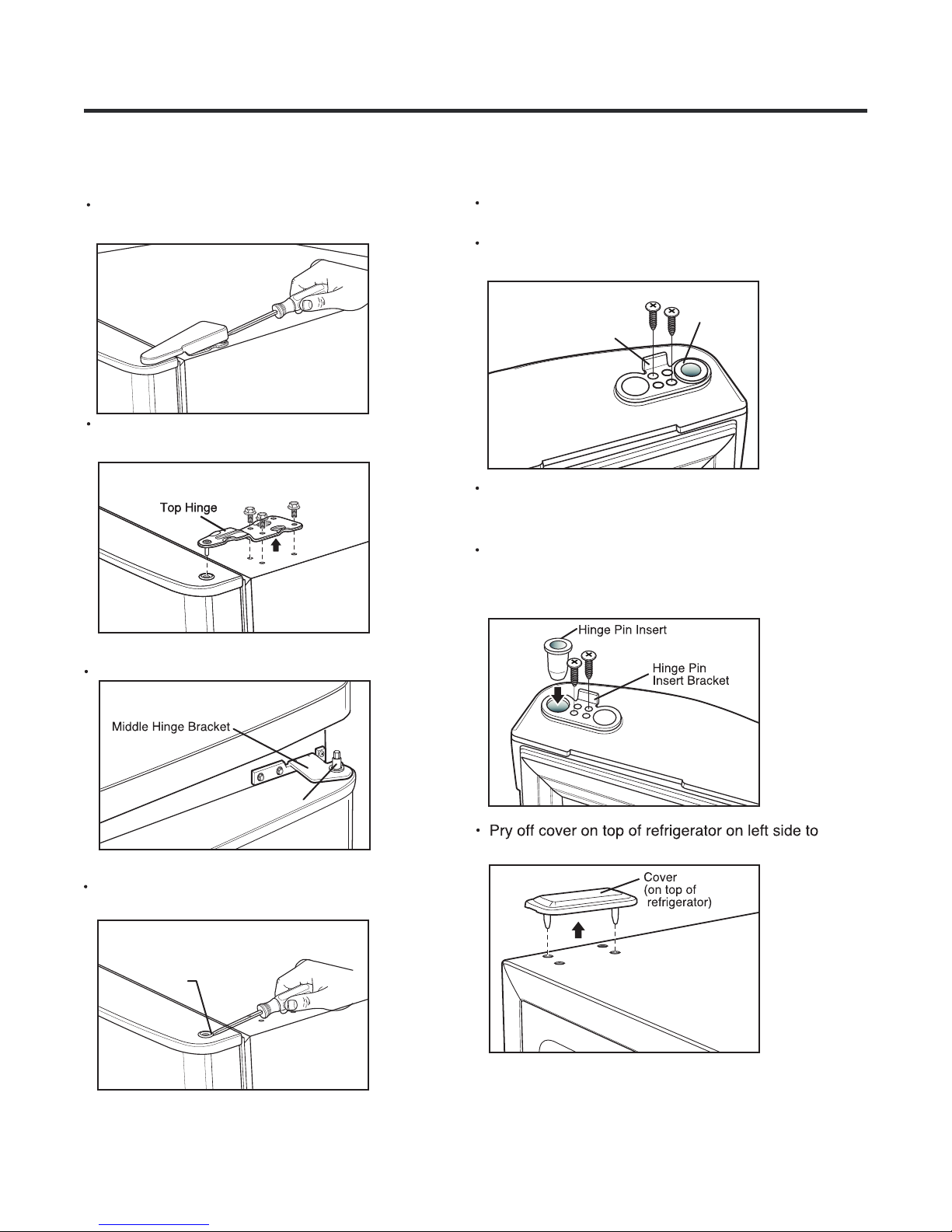
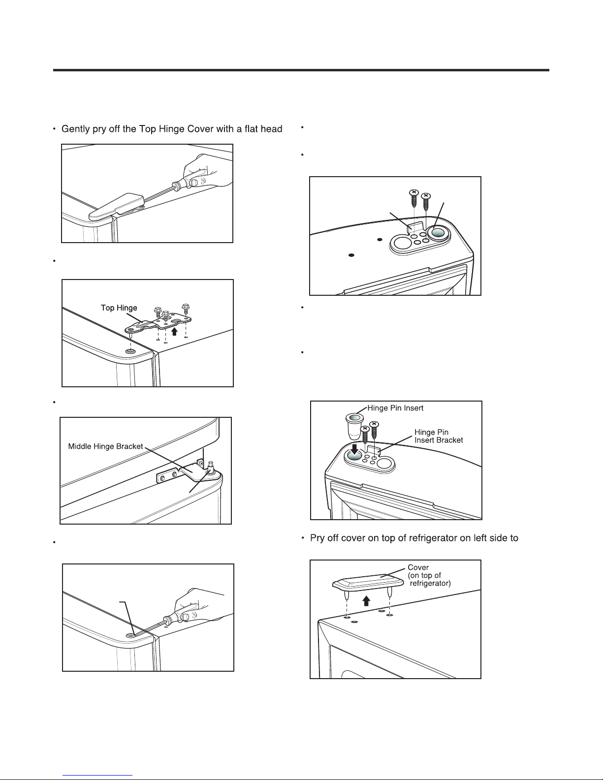
3-7-3 REVERSE DRAWER
REFRIGERATOR DOOR
Gently pry off Top Hinge Cover with a flat head.
screwdriver and remove.
Fig. 29
Turn refrigerator door upside down on a non-scratch
surface.
Loosen the 2 screws to remove the Bottom Hinge
Pin Insert Bracket with Hinge Pin Insert.
Using 10mm or 13/32-inch socket wrench, remove
the 3 bolts and lift off the Top Hinge. Set parts aside.
Fig. 30
Lift up refrigerator door slightly and remove it.
Fig. 31
Fig. 33
Hinge Pin
Insert Bracket
Hinge Pin
Insert
Remove screw on the opposite side of the door.
This screw is no longer necessary and can be
discarted.
Move the Hinge Pin Insert Bracket to the other side
of the door, keeping the same orientation, and push
the Hinge Pin Insert into the hole on the left side of
the bracket. Insert the 2 screws as shown below.
Fig. 34
Hinge Pin
Remove Hinge Pin Insert on the right side of the
door and reinstall on left side.
Fig. 32
Hinge Pin
Insert
uncover screw holes and place it on the right side.
Fig. 35
- 12 -
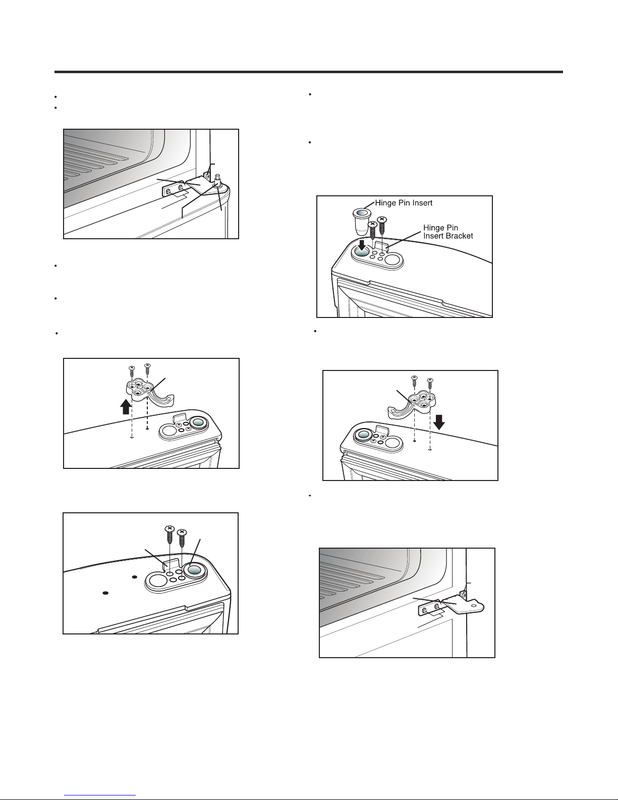
Remove Washer and set aside.
Using a 1/4 socket wrench, loosen and remove
Hinge Pin from the Middle Hinge Bracket.
Flip the middle hinge bracket and position on
left side of refrigerator and re-attach with
two bolts and a 2 phillips screws.
Fig. 21
Screws
Middle Hinge
Bracket
Bolts
Middle
Fig. 36
Hinge Pin
Use a 10mm or 13/32 inch socket wrench to remove
the 2 bolts in Middle Hinge Bracket. Remove 2
screws. Set Middle Hinge Bracket and other parts
aside.
With a flat-head screwdriver, carefully pry off and
remove the cover over the screw holes on the left side
of refrigerator housing.
Fig.37
(2)
Washer
Fig. 40
Attach Middle Hinge Pin and r .eplace washer
Put refrigerator door down over the Hinge
Pin on the Middle Hinge Pin Bracket.
Fig. 41
Washer
Middle
Hinge Pin
Remove the 2 outer screws from cabinet frame as
shown.
You will need these holes for the Middle Hinge Bracket.
Fig. 38
Place screws into outer holes on right side of cabinet.
Attach cover on the right side. Cover is force-fitted.
Fig. 39
Line up Top Hinge with holes in top of
refrigerator. Use the 3 bolts to replace the Hinge.
Fig. 42
Top Hinge Pin
Fig. 18
Tighten Bolts. Force-fit Top Hinge Cover over top
Hinge.
Fig. 43
- 13 -
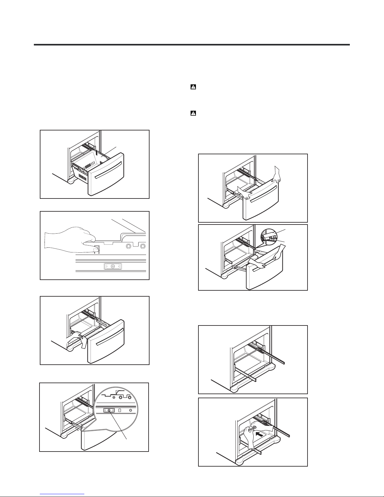
3-7-4 PULL OUT DRAWER
(a) HOW TO REMOVE PULL OUT DRAWER
IMPORTANT: To avoid possible injury, product or
property damage, you will need two people to perform
the following instructions.
• Pull the drawer open to full lower extension. Remove
durabase by lifting it from rail system.
Fig. 44
Durabase
•
Press both hangers with yours thumbs to lift it up.
Fig. 45
When removing drawer door, do not hold it
CAUTION:
by the handle. Door could fall down and you may be
injured grasp door with both hands as pictured below
When removing.
CAUTION:When laying down the drawer, be careful
not to damage the floor or hurt your feet with the sharp
edges on hinge side.
• With both hands, hold both sides of the door and pull it
up to separate it from the rails.
Fig. 48
Fig. 49
Door
supports
Rail tabes
• Separate the left and right rail cover
Fig. 46
• Remove the screws of the rail on both sides.
Fig. 47
screw
•
Push rails back into drawe cavity. With both hands,
hold the center of the bar and push it in so that both
rails go back simultaneously.
Fig. 50
Fig. 51
- 14 -
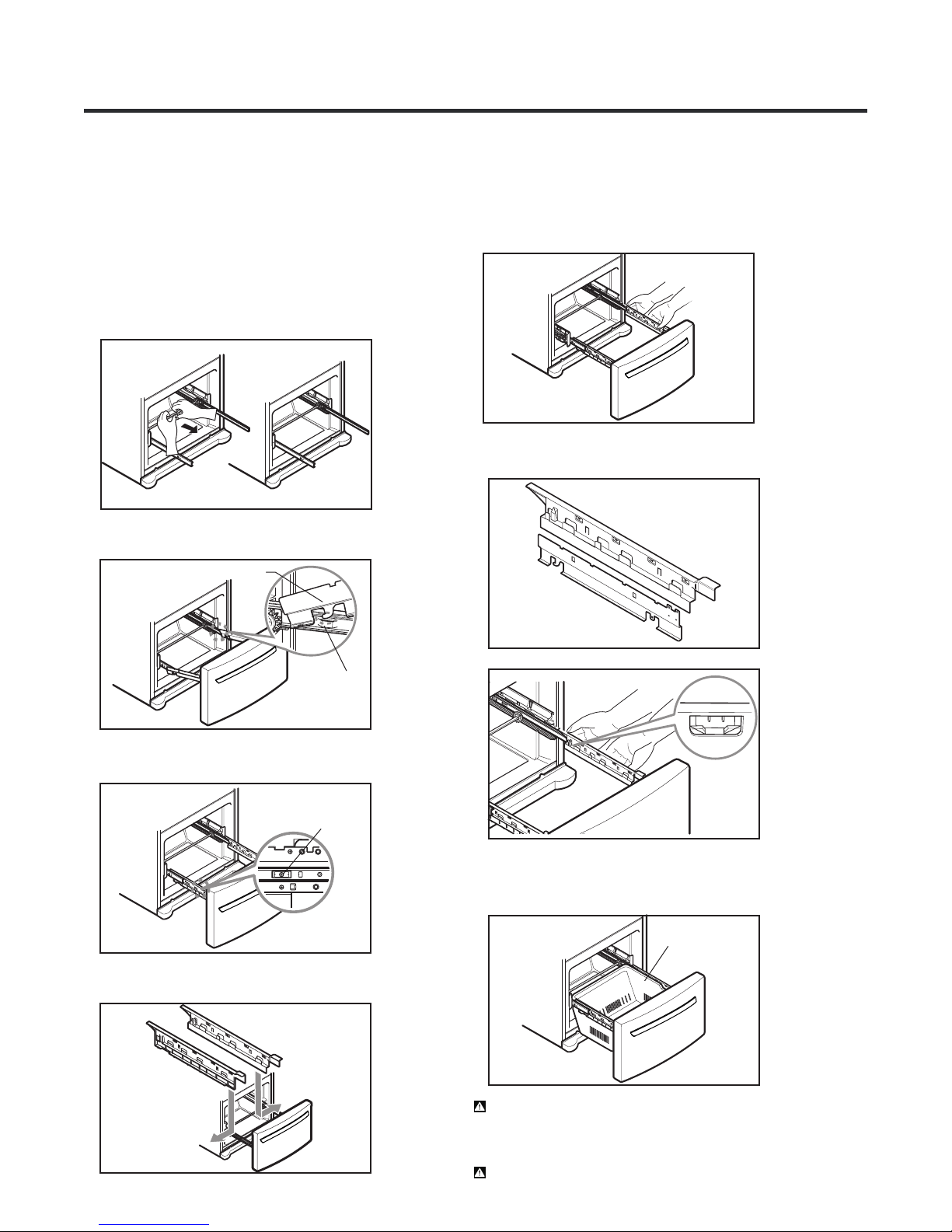
(b) HOW TO INSTALL PULL OUT DRAWER
IMPORTANT: To avoid possible injury, product or
property damage, you will need two people to perform
the following instructions.
• With both hands, hold the center of the bar and pull it
out to let both rails out to full extension simultaneously.
Fig. 52
• Hook door supports into rail tabs.
Fig. 53
Door Supports
• Align the top holes of the rail cover with the top holes of
the door supports to assemble the rail cover.
Fig. 56
•
Verify the hole’s assembly
Fig. 57
Rail tabes
• Lower door into final position and tighten the screws.
Fig. 54
Screws
•
Make sure you have a right rail cover for each side.
Right
Rail cover
Left
Rail cover
Fig.55
Fig. 58
• With the rails pulled out to full extension, insert the
durabase in the rail assembly.
Fig. 59
Durabase
WARNING:To prevent accidental child and pet
entrapment or suffocation risk. DO NOT allow them to
play inside of drawer.
WARNING:DO NOT step or sit down on Freezer Door.
- 15 -

3-7-5 HOW TO REVERSE DRAWER
DOOR HANDLE
NOTE: Handle appearance may vary from illustrations
on this page.
• Loosen the 2 set screws with the 3/32” Allen
wrench and remove the handle.
Fig. 60
Install the handle mounting fasteners
•
on the right side. Turn handle upside down.
Screw
Handle
••Loosen the handle mounting fasteners
with the 1/4” Allen wrench.
Fig. 61
fastener
Unscrew the buttons with your fingers by rotating
counterclockwise; they will loosen and fall free.
Fig. 62
Fig. 64
Install the handle by adjusting handle
•
Handle Mounting
Fastener
footprints to fit mounting fasteners. Using a
3/32” allen wrench tighten the set screws.
Fig. 65
Plug button
Install the plug buttons on the left side.
•
Plug buttons
Fig. 63
- 16 -
3-8 DOOR DISASSEMBLY
FOR SWING TYPE MODELS
3-8-1 REMOVE SWING REFRIGERATOR
AND FREEZER DOORS
Before removing the doors, remove the Base Grille.
screwdriver and remove.
Fig. 66
Use a 10mm or 13/32 inch socket wrench to remove
the 2 bolts in Middle Hinge Bracket. Remove
screws. Set Middle Hinge Bracket and other parts
aside.
Fig. 21
Screws
Middle Hinge
Bracket
(2)
Using 10mm or 13/32-inch socket wrench, remove
the 3 bolts and lift off the Top Hinge. Set parts aside.
Fig. 67
Lift up door slightly and remove it. Place door on
a non scratching surface.
Fig. 68
Fig. 69
Bolts
Middle
Hinge Pin
Washer
Carefully lift up the freezer door. Remove and place
it on a non-scratching surface.
Using a 13/32” 10mm socket wrench with a
2” extension, loosen the 2 bolts and remove
Bottom Hinge Bracket from right side.
Fig. 70
Bottom Hinge Pin
Bottom Hinge
Bracket
Hinge Pin
Remove washer and set aside.
Using a 1/4 socket wrench, loosen and remove
Hinge Pin from the Middle Hinge Bracket.
- 17 -
3-8-2 REPLACE SWING REFRIGERATOR
AND FREEZER DOORS
Reattach Bottom Hinge Bracket using the 2
previously removed bolts.
Reattach Middle Hinge Bracket with the previously
removed 2 bolts and 2 screws.
Fig. 21
Screws
Screws
(2)
Middle Hinge
Bracket
Bolts
Fig. 71
Middle Hinge Pin
Place freezer door down on Bottom Hinge Pin.
Bottom Hinge Pin
(2)
Washer
Put refrigerator door down over the Hinge
Pin on the Middle Hinge Pin Bracket.
Fig. 74
Hinge Pin
Line up Top Hinge with holes in top of
refrigerator. Use the 3 bolts to replace the Hinge.
Fig. 75
Top Hinge Pin
Fig. 72
Reattach Middle Hinge Pin. Replace washer.
Fig. 21
Screws
(2)
Washer
Fig. 73
Middle Hinge
Bracket
Bolts
Middle
Hinge Pin
Tighten Bolts. Force-fit Top Hinge Cover over top
Hinge.
Fig. 76
- 18 -
3-8-3 REVERSE SWING REFRIGERATOR
AND FREEZER DOORS
screwdriver and remove.
Fig. 77
Turn refrigerator door upside down on a non-scratch
surface.
Loosen the 2 screws to remove the Bottom Hinge
Pin Insert Bracket with Hinge Pin Insert.
Using 10mm or 13/32-inch socket wrench, remove
the 3 bolts and lift off the Top Hinge. Set parts aside.
Fig.78
Lift up refrigerator door slightly and remove it.
Fig.79
Fig.81
Hinge Pin
Insert Bracket
Hinge Pin
Insert
Remove the screw on the opposite side of the door.
This screw is no longer necessary and can be
discarted.
Move the Hinge Pin Insert Bracket to the other side
of the door, keeping the same orientation, and push
the Hinge Pin Insert into the hole on the left side of
the bracket. Insert the 2 screws as shown below.
Fig. 82
Hinge Pin
Remove Hinge Pin Insert on the right side of the
door and reinstall on left side of door.
Fig. 80
Hinge Pin
Insert
uncover screw holes and place ir on the right side.
Fig. 83
- 19 -
Remove Washer and set aside.
Using a 1/4 socket wrench, loosen and remove
Hinge Pin from the Middle Hinge Bracket.
Remove the screw on the opposite side of the door.
This screw is no longer necessary and can be
discarted.
Fig. 21
Screws
Middle Hinge
Bracket
Bolts
Middle
Fig. 84
Hinge Pin
Carefully lift up the freezer door. Remove and place
it on a non scratching surface.
Turn freezer door upside down.
With door upside down, loosen the 2 screws and
remove the Door Closer/Stop.
Fig. 85
Door Closer/Stop
(2)
Washer
Move the Hinge Pin Insert Bracket to the other side
of the door, keeping the same orientation, and push
the Hinge Pin Insert into the hole on the left side of
the bracket. Insert the 2 screws as shown below.
Fig. 87
Take Door Closer/Stop and flip. Line up screw
holes and mount on left side of door bottom with
the 2 screws. Turn door upright and set aside.
Door Closer/Stop
Fig. 88
Loosen the 2 screws to remove the Bottom Hinge
Pin Insert Bracket with Hinge Pin Insert.
Fig. 86
Hinge Pin
Insert Bracket
Hinge Pin
Insert
Use a 10mm or 13/32 inch socket wrench to remove
the 2 bolts in Middle Hinge Bracket. Remove 2
screws. Set Middle Hinge Bracket and other parts
aside.
Fig. 21
Screws
Screws
(2)
Middle Hinge
Bracket
Bolts
Fig.89
(2)
- 20 -
 Loading...