

CAUTION
BEFORE SERVICING THE UNIT,
READ THE SAFETY PRECAUTIONS IN THIS MANUAL.
REFRIGERATOR
SERVICE MANUAL
R
795.77192600
795.77199600
795.77194600
795.77193600
795.77196600
795.77542600
795.77549600
795.77544600
795.77543600
795.77546600
795.77552600
795.77559600
795.77554600
795.77553600
795.77556600
795.77712700
795.77713700
795.77719700
795.77729700
P/No. 3828JL8796A (Last Revision: MARCH. 2. 2006)
Model #s:

- 2 -
SAFETY PRECAUTIONS....................................................................................................................................................... 2
1. SPECIFICATIONS............................................................................................................................................................... 3
2. PARTS IDENTIFICATION................................................................................................................................................... 4
3. DISASSEMBLY.............................................................................................................................................................. 5-12
DOOR.............................................................................................................................................................................. 5-7
TO REMOVE THE DISPENSER .........................................................................................................................................7
FAN AND FAN MOTOR...................................................................................................................................................... 8
DEFROST CONTROL ASSEMBLY.................................................................................................................................... 8
LAMP.................................................................................................................................................................................. 8
CONTROL BOX-REFRIGERATOR.................................................................................................................................... 8
MULTI DUCT ...................................................................................................................................................................... 8
HOW TO REMOVE AND REINSTALL THE PULLOUT DRAWER................................................................................ 9-12
TRIM KIT ASSEMBLY AND AISASSEMBLY METHOD(795.77719, 77729 models only.............................................13-15
4. ADJUSTMENT............................................................................................................................................................. 16-17
COMPRESSOR................................................................................................................................................................ 16
PTC-STARTER................................................................................................................................................................. 16
OLP (OVERLOAD PROTECTOR).................................................................................................................................... 17
TO REMOVE THE COVER PTC.......................................................................................................................................17
5. CIRCUIT DIAGRAM.......................................................................................................................................................... 18
6. TROUBLESHOOTING................................................................................................................................................. 19-24
COMPRESSOR AND ELECTRIC COMPONENTS.......................................................................................................... 19
PTC AND OLP.................................................................................................................................................................. 20
OTHER ELECTRICAL COMPONENTS ........................................................................................................................... 21
SERVICE DIAGNOSIS CHART........................................................................................................................................ 22
REFRIGERATION CYCLE .......................................................................................................................................... 23-24
7. OPERATION PRINCIPLE & REPAIR METHOD OF ICEMAKER .............................................................................. 25-28
8. DESCRIPTION OF FUNCTION & CIRCUIT OF MICOM ........................................................................................... 29-40
CONTENTS
Please read the following instructions before servicing your refrigerator.
1. Unplug the power before handling any elctrical componets.
2. Check the rated current, voltage, and capacity.
3. Take caution not to get water near any electrical components.
4. Use exact replacement parts.
5. Remove any objects from the top prior to tilting the product.
SAFETY PRECAUTIONS
1-1 DISCONNECT POWER CORD BEFORE
SERVICING
IMPORTANT – RECONNECT ALL
GROUNDING DEVICES
All parts of this appliance capable of conducting electrical
current are grounded. If grounding wires, screws, straps,
clips, nuts or washers used to complete a path to ground
are removed for service, they must be returned to their
original position and properly fastened.
1-2 IMPORTANT NOTICE
This information is intended for use by individuals
possessing adequate backgrounds of electrical, electronic
and mechanical experience. Any attempt to repair a major
appliance may result in personal injury and property
damage. The manufacturer or seller cannot be responsible
for the interpretation of this information, nor can it assume
any liability in connection with its use.
1-3 ELECTRICAL SPECIFICATIONS
Temperature Control (Freezer Compartment)...-6°F to +8°F
Defrost Control.................Total Comp Running Time : 7 hrs
Defrost Thermostat.......................................................46°F
Electrical Rating : 115VAC, 60Hz.................................1-5 A
Maximum Current Leakage.......................................0.5 mA
Maximum Ground Path Resistance....................0.14 Ohms
Energy Consumption .....21 cu.ft. 484 kWh/yr (Energy Star)
.......................................25 cu.ft. 499 kWh/yr (Energy Star)
1-4 NO LOAD PERFORMANCE
CONTROL POSITION: MID/MID
And Ambient of: ..................70°F..................................90°F
Fresh Food, °F....................33°F to 41°F.........33°F to 41°F
Frozen Food, °F..................-4°F to +4°F..........-4°F to +4°F
Percent Running Time........35%-45%.................50°F-70°F
1-5 REFRIGERA TION SYSTEM
Minimum Compressor Capacity Vacuum ............... 20 MIN.
Minimum Equalized Pressure
@ 70°F ....................................................... 49 PSIG
@ 90°F ....................................................... 56 PSIG
Refrigerant R134a ................................................. 4.06 oz.
Compressor ..................................................... 830 BTU/hr
1-6 INSTALLATION
Clearance must be provided at top, sides and rear of the
refrigerator for air circulation.
AT TOP ......................................................................... 1 in
AT SIDES ...................................................................... 1 in
AT REAR ...................................................................... 2 in
1-7 REPLACEMENT PARTS
Relay............................................................. 6748C-0004D
Overload ....................................................... 6750C-0005P
Defrost Thermostat ...................................... 6615JB2005H
Defrost Heater ............................................. 5300JK1005D
Evaporator Fan Motor .................................. 4681JK1004A
Capacitor .................................................... 0CZZJB2012G
Compressor (Hi-Side) .................................. 2521C-A5719
Evaporator (Lo-Side) .................................... 5421JJ0006A
*5421JJ0007A
Condenser .................................................... 5403JJ1004B
Dryer ............................................................ 5851JA2008A
Condenser Fan Motor .................................. 4681JB1029D
Temperature Control .................................... 6871JB1439A
Main Control.................................................. 6871JB1423B
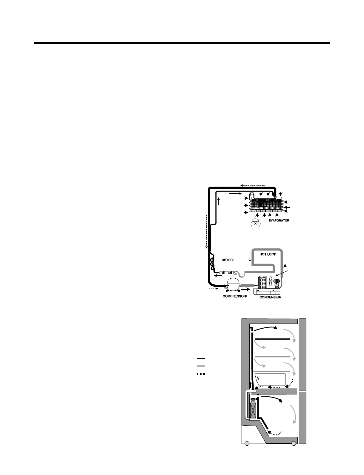
1-8 AIR FLOW / CIRCULATION D’AIR
1. SPECIFICATIONS
- 3 -
EVAPORATOR
COLD AIR
MIXED AIR
AIR RETURN TO
EVAPORATOR
FRESH FOOD
FREEZER
Ò
Vegetable box
EVAPORTOR FAN MOTOR
CONDENSER FAN MOTOR
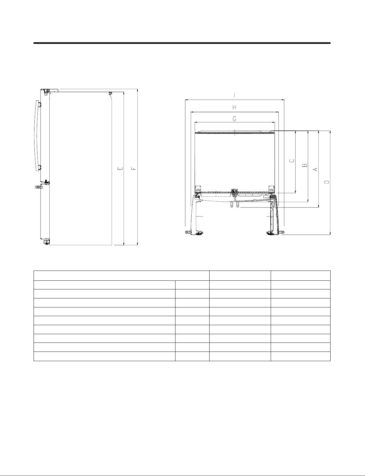
1-9 DIMENSIONS
- 4 -
Description 795.777** 795.775**
Depth w/ Handles A 30 in. 34 1/4 in.
Depth w/o Handles B 27 1/2 in. 31 3/4 in.
Depth w/o Door C 23 5/8 in. 27 7/8 in.
Depth (Total with Door Open) D 42 1/4 in. 46 1 /2 in.
Height to Top of Case E 68 3/8 in. 68 3/8 in.
Height to Top of Door Hinge F 69 3/4 in. 69 3/4 in.
Width G 35 3/4 in. 35 3/4 in.
Width (door open 90 deg. w/o handle) H 39 1/4 in. 39/1/4 in.
Width (door open 90 deg. w/ handle) I 44 1/4 in. 44 1/4 in.
- 5 -
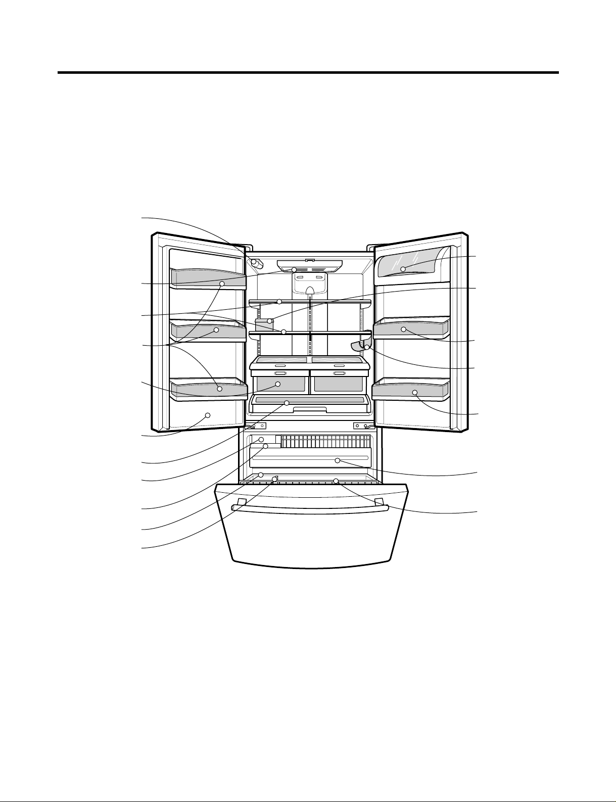
2. PARTS IDENTIFICATION
Refrigerator Light
Refrigerator
Shelves
Super Fresh
Crisper with
Tilt-Out
Compartment
Adjust Cube
Ice Maker
Glide'N'Serve
Ice Bin
Durabase
Divider
Pull out Drawer
Tilt-Out
Door Basket
(795.7754*, 7755*
Model Only)
Modular
Door Bins
Modular
Door Bins
Bottle Holder
(795.7755*,77729
Models Only)
Dairy Bin
Egg Box
Modular
Door Bins
Filter
Cover Front
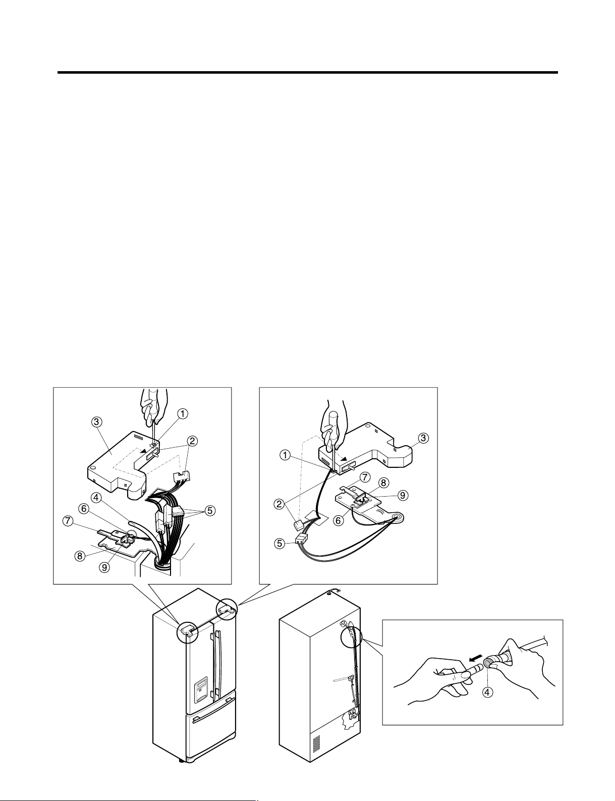
3-1 REMOVING AND REPLACING REFRIGERATOR DOORS
● Removing Refrigerator Door
ww
CAUTION: Before you begin, unplug the refrigerator. Remove food and bins from doors.
uu
Left Door
1. Disconnect water supply tube by pushing back on the disconnect ring (4).
2. Open door. Loosen top hinge cover screw (1).
Use flat tip screwdriver to pry back hooks on front underside of cover (3). Lift up cover.
3. Disconnect door switch wire harness (2). Remove cover.
4. Attach the tube on the door with door.
5. Pull out the tube.
6. Disconnect the three wire harnesses (5). Remove the grounding screw (6).
7. Rotate hinge lever (7) counterclockwise and remove. Lift top hinge (8) free of hinge lever latch (9).
ww
CAUTION: When lifting hinge free of latch, be careful that door does not fall forward.
8. Lift door up from middle hinge pin (10) and remove door.
9. Place door, inside facing up, down onto a non-scratching surface.
uu
Right Door
1. Open door. Loosen top hinge cover screw (1). Lift up cover (3).
2. Disconnect door switch wire harness (2). Remove cover.
3. Disconnect wire harness (5). Remove the grounding screw (6).
4. Rotate hinge lever (7) clockwise and remove. Lift top hinge (8) free of hinge lever latch (9).
ww
CAUTION: When lifting hinge free of latch, be careful that door does not fall forward.
5. Lift door up from middle hinge pin (10) and remove door.
6. Place door, inside facing up, down onto a non-scratching surface.
- 6 -
3. DISASSEMBLY
4
3
1
4
6
2
7
8
9
5
1
7
8
3
2
6
5
9
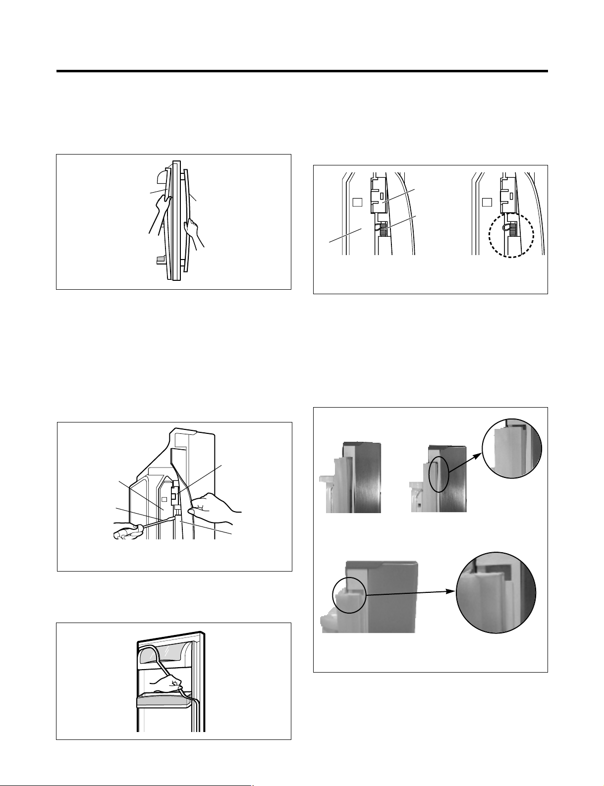
3-2 DOOR
● Door Gasket Removal
1. Remove door frame cover
Starting at top of cover and working down, snap cover
out and away from door.
2. Remove gasket bracket clips
There are two clips on each door. Start bracket removal
near one of the middle clips.
1) Pull gasket back to expose gasket bracket clip and
door frame.
2) Insert a flat tip screwdriver into seam between gasket
bracket and door frame and pry back until clips snaps
out.
3) Continue prying back along seam until all clips snap
out.
3. Remove gasket
Pull gasket free from gasket channel on the three
remaining sides of door.
● Door Gasket Replacement
1. Insert gasket bracket clips
1) Insert gasket bracket edge beneath door frame edge.
2) Turn upper gasket bracket spring so that the spring
ends are in the door channel.
3) Push in clip until you hear it snap securely into place.
4) Push in remaining two clips until you hear each snap
securely into place.
Note: Make sure that no part of gasket bracket edge
protrudes from beneath door frame edge.
2. Insert gasket into channel
1) Snap gasket assembly into the door bracket.
<Inserting the Gasket Assembly into the Bracket Door>
- 7 -
Frame Cover
Handle
Figure 1
Figure 2
Figure 3
Door
Frame
Gasket
Bracket Clip
Spring
IncorrectCorrect
Figure 4
Figure 5
Correct
Incorrect
Gasket
Door
Bracket Clip
Frame
Flat Tip
Screwdriver
Gasket
Bracket
2) Press gasket into channels on the three remaining
sides of door.
3. Replace door frame cover
Starting at top of cover and working down, snap cover
back into door.
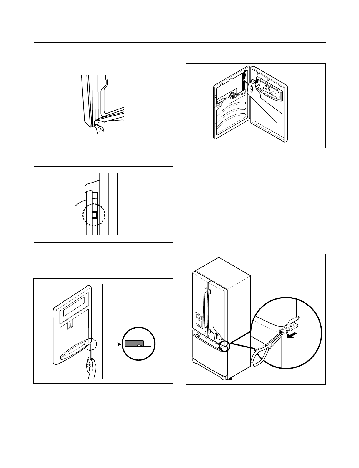
3-3 TO REMOVE THE DISPENSER
1. Use fiat tip screwdriver to pry back hooks on botton
underside of cover dispenser.
2. Pry off cover dispenser.
Disconnect wire harness.
3. Replace cover dispenser in opposite manner and order
of removal.
3-4 DOOR ALIGNMENT
If the space between your doors is uneven, follow the
instructions below to align the doors:
1. With one hand, lift up the door you want to raise at
middle hinge.
2. With other hand, use pliers to insert snap ring as shown.
3. Insert additional snap rings until the doors are aligned.
(Three snap rings are provided with unit.)
- 8 -
Figure 6
Figure 8
Figure 9
Figure 7
Figure 10
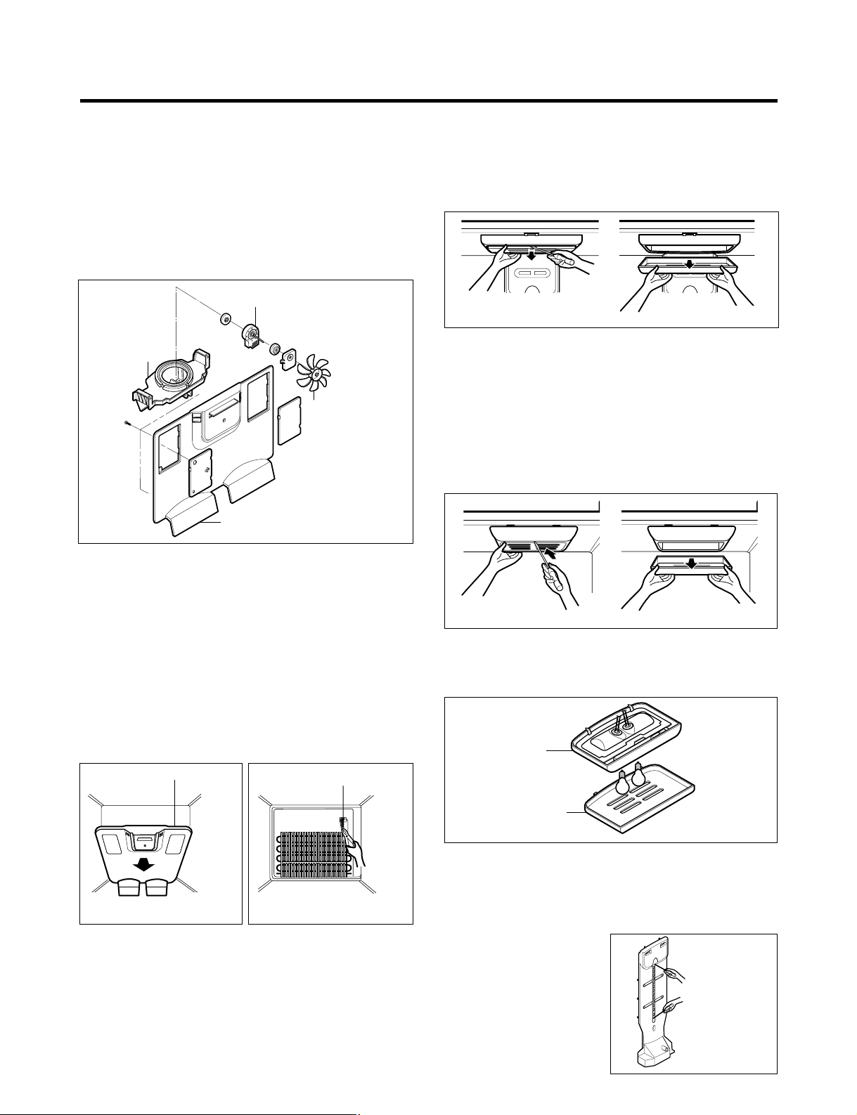
3-5 FAN AND FAN MOTOR
1. Remove the freezer shelf. (If your refrigerator has an
icemaker, remove the icemaker first)
2. Remove the plastic guide for slides on left side by
unscrewing phillips head screws.
3. Remove the grille by pulling it out and by loosening a screw.
4. Remove the Fan Motor assembly by loosening 2 screws
and disassemble the shroud.
5. Pull out the fan and separate the Fan Motor and Bracket.
3-6 DEFROST CONTROL ASSEMBLY
Defrost Control assembly consists of Defrost Sensor and
FUSE–M.
The Defrost Sensor works to defrost automatically . It is
attached to the metal side of the Evaporator and senses its
temperature. At 161.6°F(72°C), it turns the Defrost Heater off.
Fuse-M is a safety device for preventing over-heating of
the Heater when defrosting.
1. Pull out the grille assembly. (Figure 12)
2. Separate the connector with the Defrost Control
assembly and replace the Defrost Control assembly
after cutting the Tie Wrap. (Figure 13)
3-7 LAMP
3-7-1 Refrigerator Compartment Lamp
1. Unplug Refrigerator, or disconnect power at the circuit
breaker.
2. If necessary, remove top shelf or shelves.
3. Using a flat instrument, gently pry the cover loose in the
front as shown. Rotate downward to remove rear tabs.
4. Make sure the bulbs are cool to the touch.
Turn bulbs counterclockwise to remove.
5. Assemble in reverse order by snapping the Lamp Cover
in, engaging the rear tabs followed by the front tabs.
(Max. 60 W-2EA)
3-7-2 Freezer Compartment Lamp
1. Unplug refrigerator power cord form outlet.
2. Using a flat instrument, gently pry the lamp cover loose
in the front as shown. Rotate downward to remove the
rear tabs.
3. Make sure the bulb is cool to the touch. Turn the bulb
counterclockwise to remove.
4. Replace with a new 60-watt appliance bulb.
5. Insert tabs on back of cover into slots in freezer ceiling.
Push cover up to snap front into place.
3-8 CONTROL BOX-REFRIGERATOR
1. First, remove all shelves in the refrigerator, than remove
the Refrigerator control Box by loosening 2 screws.
2. Remove the Refrigerator Control Box by pulling it
downward.
3. Disconnect the lead wire on the right position and
separate the lamp sockets.
3-9 MULTI DUCT
1. Remove an upper and
lower Cap by using a flat
screwdriver, and loosen 2
screws. (Figure 17)
2. Disconnect the lead wire
on the bottom position.
- 9 -
BRACKET
MOTOR
GRILLE
FAN MOTOR
FAN
Figure 11
GRILLE ASSEMBLY
Figure 12
DEFROST-CONTROL
ASSEMBLY
Figure 13
Figure 14
Figure 15
CONTROL BOX
COVER LAMP
Figure 16
Figure 17
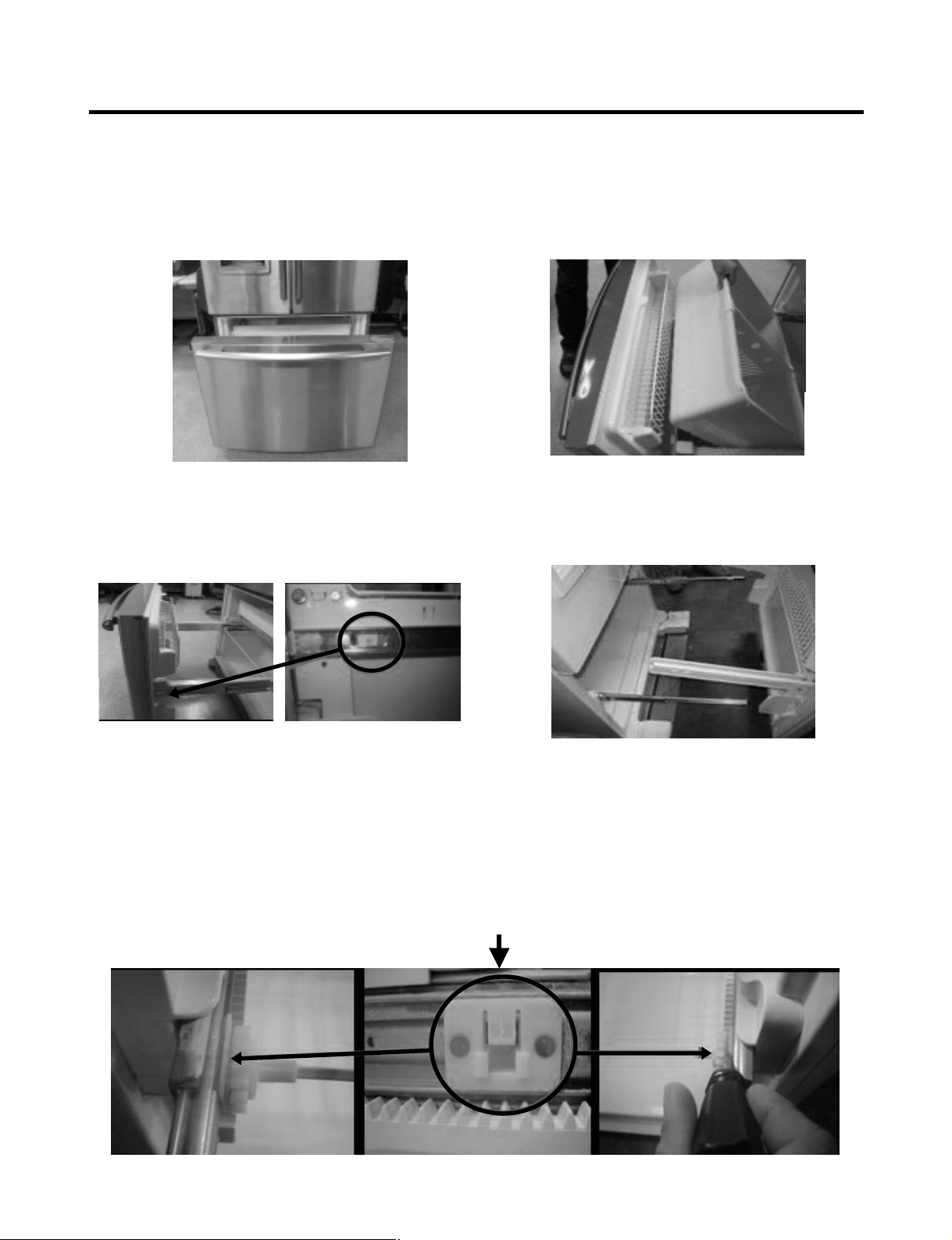
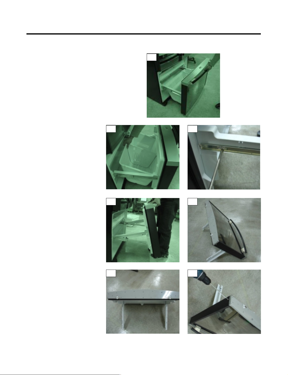
3-10 HOW TO REMOVE AND REINSTALL THE PULLOUT DRAWER
3-10-1 FOLLOW STEPS TO REMOVE
- 10 -
Step 1) Open the freezer door.
Step 3) Remove the two screws from the guide rails (one
from each side).
Step 2) Remove the lower basket.
Step 4) Lift the freezer door up to unhook it from the rail
support and remove.
Pull both rails to full extension.
Step 5) First: Remove the gear from the left side first by releasing the tab behind the gear, place a screwdriver between the
gear and the tab and pull up on the gear.
Second: Remove the center rail.
Third: Remove the gear from the right side by following the same steps for the left side.
NOTE: THIS TAB MUST BE PUSHED IN TO RELEASE THE GEAR.
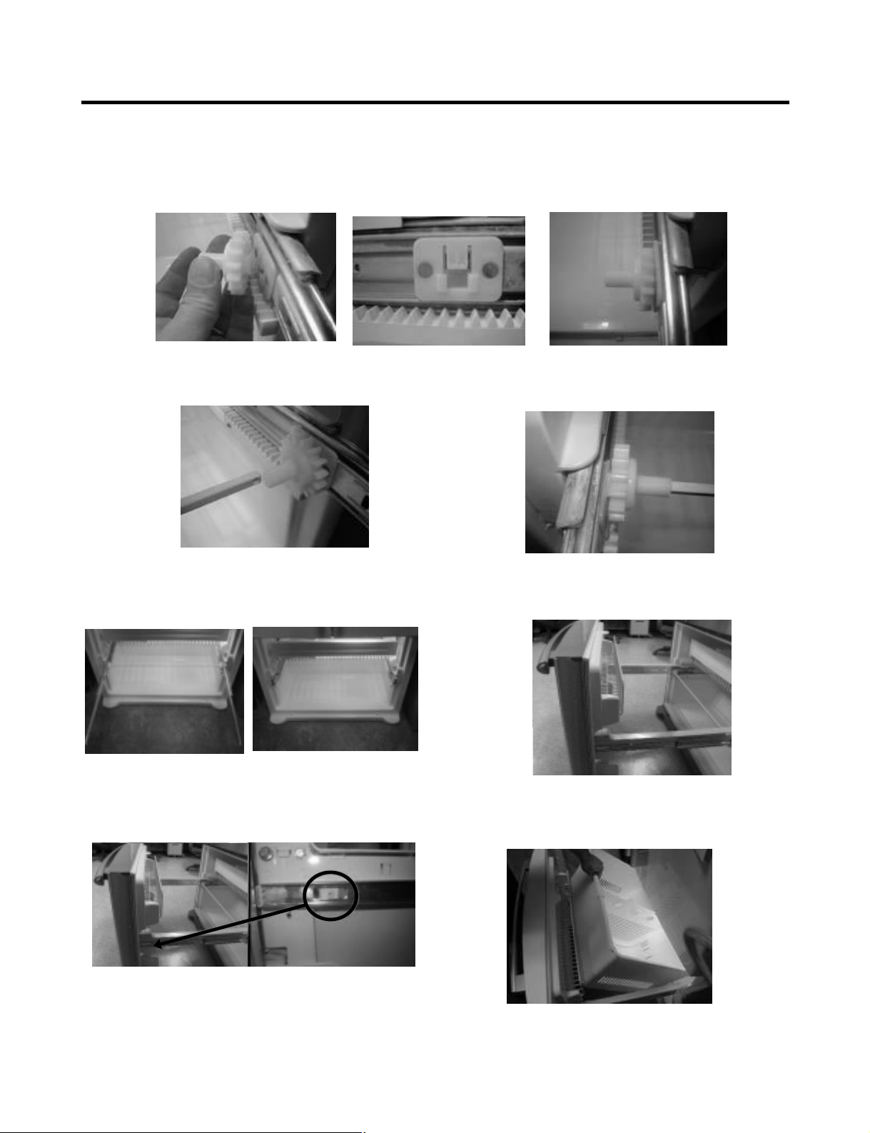
3-10-2 FOLLOW STEPS TO REINSTALL
Step 1) Reinstall the right side gear into the clip.
Step 2) Insert the rail into the right side gear. Gears do not
need to be perpendicular to each other.
Step 4) The rail system will align itself by pushing the rails
all the way into the freezer section.
Pull the rails back out to full extension.
Step 6) Reinstall the two screws into the guide rails
(one from each side).
Step 3) Insert the rail into the left side gear, and insert the
gear into the clip.
Step 5) Reinstall the freezer door by inserting the rail tabs
into the guide rail.
Step 7) Reinstall the lower basket, and close the freezer
door.
- 11 -
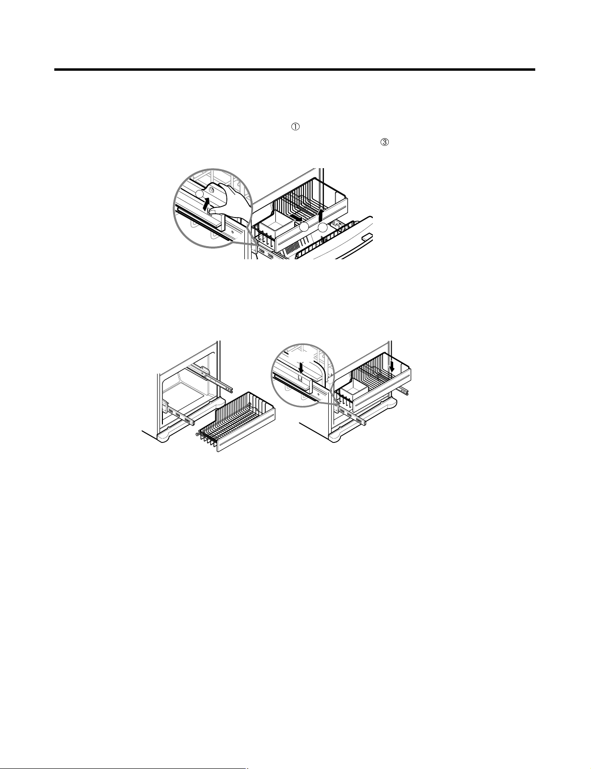
3-10-3 PULL OUT DRAWER
To separate the drawer, push the front left and right hooks in
direction to pull up and remove.
Then gently lift the gear part of rear left and right side of the drawer and pull it out in
direction.
To install, reposition the gear part of rear left and right side of the drawer after pulling out both rails as much as possible,
and gently push down both left and right side while checking the hook on the front part.
- 12 -
1
3
2
Hook
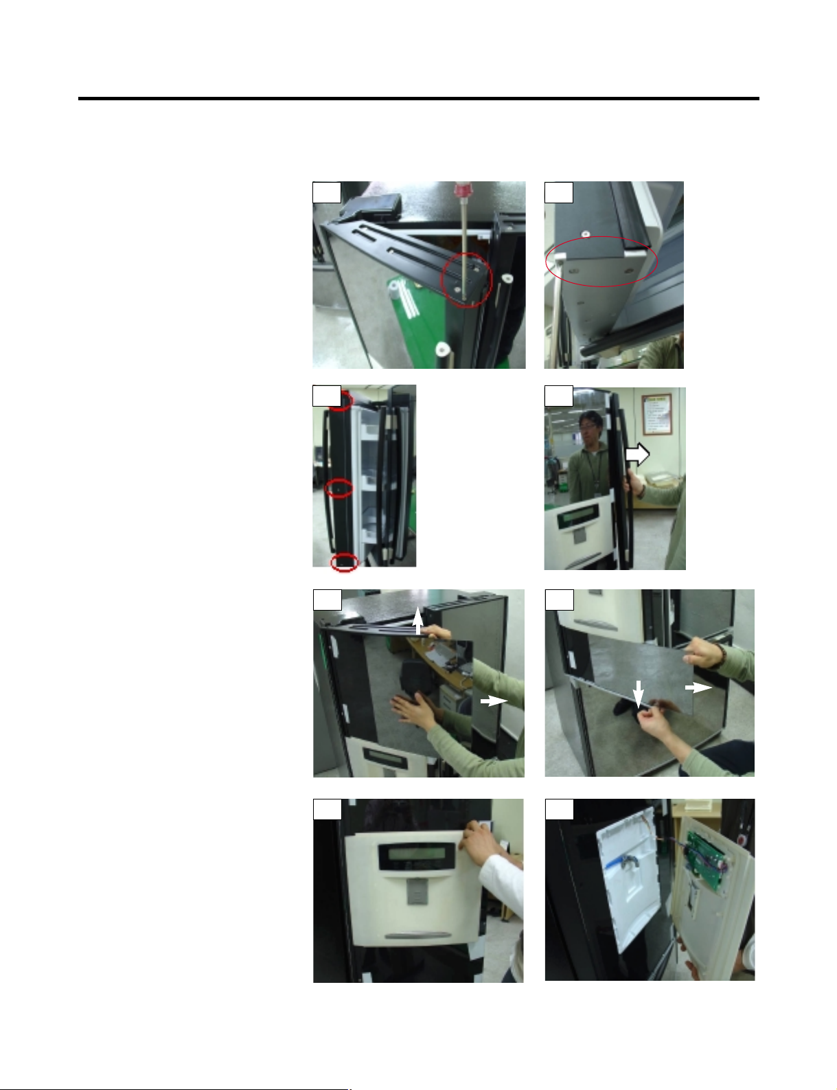
3-11 TRIM KIT ASSEMBLY AND AISASSEMBLY METHOD (795.77719,77729 MODELS ONLY)
3-11-1 ASSEMBLY AND DISASSEMBLY METHOD OF LEFT DOOR GLASS AND DISPLAY OF THE REFRIGERATOR
1. Remove the 2 screws on the top
refrigerator door trim, circled in Photo
# 1.
2. Remove the 2 screws on the bottom
refrigerator door trim, circled in photo
# 2.
3. While holding the door handle (to
prevent it from falling) remove the 3
screws on the side trim that holds the
handle on.(see photo # 3)
4. Remove the door handle. (see photo
# 4)
5. While lifting up on the top door trim,
slide the glass front (above the
dispenser) to the right to remove it.
(see photo # 5)
6. While pulling down on the bottom door
trim, slide the glass front (below the
dispenser) to the right to remove it.
(see photo # 6)
7. Once the glass is removed, the
dispenser cover can be removed by
pulling it out by the right side and gently
pulling out of the left door trim slot. (see
photos 7 & 8)
8. The right side door glass is removed
in the same manner as the left.
However because it will not have the
dispenser the glass will be one
piece.
9. Reassemble in reverse order.
- 13 -
1
3
5
7 8
6
4
2
3-11-2 ASSEMBLY AND DISASSEMBLY METHOD OF FREEZER DOOR AND GLASS
1. Fully open the freezer drawer
as shown in photo # 1.
2. Lift out the freezer basket as
shown in photo # 2.
3. Remove the 2 screws
(one on each side shown in photo # 3.
4. Hold the freezer handle and pull
up to remove the door assembly,
as shown in photo # 4.
5. Put the freezer door facing down
(on a clean soft surface to prevent
scratching the top trim) as shown in
photo # 5.
6. Remove all the screws hold the bottom
door trim in place. (be careful not to
remove the 2 screws circled in
photo # 6).
7. Remove the screw at the bottom of
each side trim shown in photo # 7.
(continued on the next page)
- 14 -
1
2 3
4 5
6 7
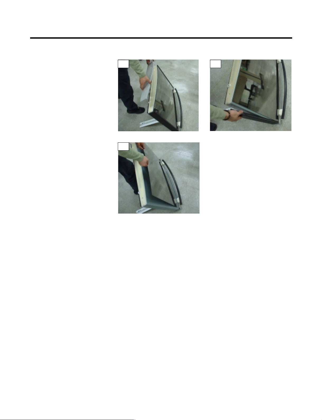
3-11-2 ASSEMBLY AND DISASSEMBLY METHOD OF FREEZER DOOR AND GLASS
8. Pull off the bottom cover as shown in
photo # 8.
9. Remove one of the side trim pieces by
pulling it out slightly the up to remove
it from the top door trim. As shown in
photo # 9.
10. Carefully pull out the freezer door
glass as shown in photo # 10.
11. Reassemble in reverse order.
- 15 -
8
10
9
4-1 COMPRESSOR
4-1-1 Role
The compressor intakes low temperature and low pressure
gas from the evaporator of the refrigerator and compresses
this gas to high-temperature and high-pressure gas. It then
delivers the gas to the condenser.
4-1-2 Composition
The compressor includes overload protection. The PTC
starter and OLP (overload protector) are attached to the
outside of the compressor. Since the compressor is
manufactured to tolerances of 1 micron and is hermetically
sealed in a dust and moisture-free environment, use
extreme caution when performing repairs.
4-1-3 Note for Usage
(1) Be careful not to allow over-voltage and over-current.
(2) If compressor is dropped or handled carelessly, poor
operation and noise may result.
(3) Use proper electric components appropriate to the
Particular Compressor in your product.
(4) Keep Compressor dry.
If the Compressor gets wet (in the rain or a damp
environment) and rust forms in the pin of the Hermetic
Terminal, poor operation and contact may result.
(5) When replacing the Compressor, be careful that dust,
humidity, and soldering flux don’t contaminate the inside
of the compressor. Dust, humidity, and solder flux
contaminate the cylinder and may cause noise,
improper operation or even cause it to lock up.
4-2 PTC-STARTER
4-2-1 Composition of PTC-Starter
(1) PTC (Positive Temperature Coefficient) is a no-contact
semiconductor starting device which uses ceramic
material consisting of BaTiO
3.
(2) The higher the temperature is, the higher the resistance
value. These features are used as a starting device for
the Motor.
4-2-2 Role of PTC-Starter
(1) The PTC is attached to the Sealed Compressor and is
used for starting the Compressor Motor.
(2) The compressor is a single-phase induction motor.
The starting operation, the PTC allows current flow to
both the start winding and main winding.
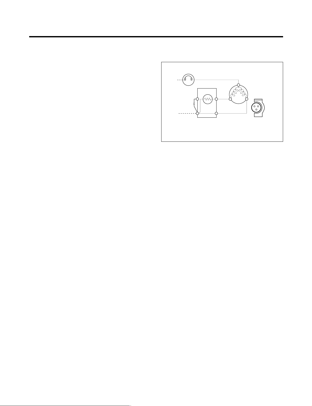
4-2-3 PTC-Applied Circuit Diagram
● Starting Method for the Motor
4-2-4 Motor Restarting and PTC Cooling
(1) It requires approximately 5 minutes for the pressure to
equalize before the compressor can restart.
(2) The PTC device generates heat during operation.
Therefore, it must be allowed to cool before the
compressor can restart.
4-2-5 Relation of PTC-Starter and OLP
(1) If the compressor attempts to restart before the PTC
device is cooled, the PTC device will allow current to
flow only to the main winding.
(2) The OLP will open because of the over current
condition. This same process will continue (3 to 5
times) when the compressor attempts to restart until
the PTC device has cooled. The correct OLP must be
properly attached to prevent damage to the
compressor.
Parts may appear physically identical but could have
different electrical ratings. Replace parts by part
number and model number. Use only approved
substitute parts.
4-2-6 Note for Using the PTC-Starter
(1) Be careful not to allow over-voltage and over-current.
(2) Do not drop or handle carelessly.
(3) Keep away from any liquid.
If liquid such as oil or water enters the PTC,
PTC materials may fail due to breakdown of their
insulating capabilities.
(4) If the exterior of the PTC is damaged, the resistance
value may be altered. This can cause damage to the
compressor and result in a no-start or hard-to-start
condition.
(5) Always use the PTC designed for the compressor and
make sure it is properly attached to the compressor.
Parts may appear physically identical but could have
different electrical ratings. Replace parts by part
number and model number. Use only approved
substitute parts.
4. ADJUSTMENT
- 16 -
PTC STARTER
SEALED
TERMINAL
COMPRESSOR
MOTOR
C
M
S
M
3
6
5
2
S
N
L1
OVERLOAD PROTECTOR
Resistance Starter Capacitor Running
PTC
Figure 18

4-3 OLP (OVERLOAD PROTECTOR)
4-3-1 Definition of OLP
(1) OLP (OVERLOAD PROTECTOR) is attached to the
Compressor and protects the Motor by opening the
circuit to the Motor if the temperature rises and
activating the bimetal spring in the OLP.
(2) When high current flows to the Compressor motor, the
Bimetal works by heating the heater inside the OLP,
and the OLP protects the Motor by cutting off the
current flowing to the Compressor Motor.
4-3-2 Role of the OLP
(1) The OLP is attached to the Sealed Compressor used
for the Refrigerator. It prevents the Motor Coil from
being started in the Compressor.
(2) For normal operation of the OLP, do not turn the Adjust
Screw of the OLP in any way.
4-4 TO REMOVE THE COVER PTC
(1) Remove the Cover Back M/C.
(2) Disconnect two housing upper side of comp connected
in.
(3) Loosen two screws on comp base.
(4) Use a L-shaped flap tool to pry off the cover.
(5) Assembly in reverse order of disassembly.
- 17 -
Part
Customer part
number
Lot code/
date code
330 FBYY -S1 BOX98
12345678
Physical
termination
part number
Electrical
characteristics
part number
No. Name
Base, phenolic
(UL 94 V-0 rated)
Movable arm support, plated steel
Stationary contact support,
plated steel
Heater support, plated steel
Heater, resistance alloy
Disc, thermostatic alloy
Movable arm, spring temper
copper alloy
Contact, movable, silver on copper
Contact, stationary, silver on copper
Slug, plated steel
Cover, polyester
(UL 94 V -0 rated)
Pin connector, plated copper alloy
(To engage 2.33/2.66 mm dia. pin)
Quick-connect terminal, brass,
conforms to UL 310, MEMA
DC-2, DIN 46344
(OVERLOAD PROTECTOR cross section)
Figure 19
2
3
1

5. CIRCUIT DIAGRAM
- 18 -
CIRCUIT DIAGRAMS

6. TROUBLESHOOTING
- 19 -
6-1 COMPRESSOR AND ELECTRIC COMPONENTS
1
2
3
4
5
2
5
5
3
5
1
43
YES
NO
YES
The range of resistance is between 1~50Ω(ok)
Open or short
YES
YES
NO
NO
Power Source.
No Voltage.
(Rated Voltage
±10%)?
Replace OLP.
Reconnect.
Reference Page12.
Reference Page12.
Did
compressor
start?
Compressor
is OK
Replace the
compressor
Check connection
condition.
OLP disconnected?
Advise customer that
power supply needs to be
checked by an electrician.
Replace
Compressor.
Supply
voltage rating
with ±10%.
Applied voltage isn't
in range of Rating
Voltage ±10%.
Remove PTC-Starter
from Compressor and
measure voltage
between Terminal C of
Compressor and
Terminals 5 or 6 of PTC.
Check resistance
between M-C, S-C and
M-S in Motor
Compressor.
Check resistance of
two terminals in
PTC-Starter.
Check resistance of two
terminals in OLP.
Check the power supply
under load.
(Compressor attempting
to re-start after being off
for 5 minutes).
Check
resistance of
Motor
Compressor.
Check
resistance of
PTC-Starter.
Check OLP.
Check
starting state.

- 20 -
6-2 PTC AND OLP
65
Shows continuity
Open
Normal operation of
Compressor is
impossible or poor.
Separate PTC-Starter
from Compressor and
measure resistance
between No. 5 and 6
of PTC-Starter with a
Tester.
(Figure 20)
Separate OLP from
Compressor and check
resistance value
between two terminals
of OLP with a Tester.
(Figure 21)
Observation value is
115V/60Hz : 6.8Ω±30%
The resistance value
is 0Ω (short) or
∞ (open).
Check another
electric component.
Replace OLP.
Replace PTCStarter.
Figure 20
Figure 21
- 21 -
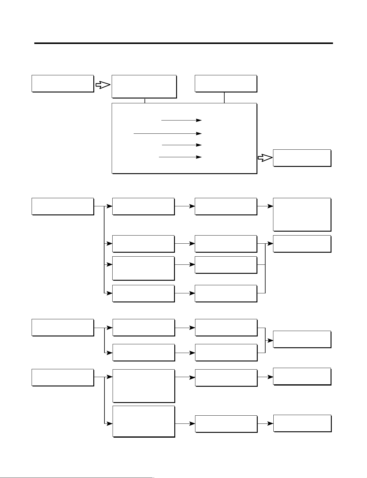
▼ Not cooling at all
▼ Poor cooling performance
Compressor
doesn't run.
Compressor runs
poorly.
Check starting
voltage.
Check for open short or
incorrect resistance readings
in the following components
a. Starting devices
b. OLP
c. Compressor coil
d. Wiring harness
Low voltage.
Short, open, or broken.
Poor contact
or shorted.
Coil open or shorted.
Poor contact
or shorted.
Poor or broken or
open contact.
Shorted.
Lack of capacity.
Replace
indicated component.
Advise customer that
the Power supply
needs to be checked
by an electrician.
Replace
indicated component.
Cause
Check voltage at
starting devices.
Check current flowing
in sub-coil of
Compressor.
Check rating of OLP.
Fan motor
doesn't run.
Heavy frost buildup on
EV APORATOR.
Wire is open or
shorted.
Coil is shorted
or open.
Open.
Open.
Replace
Defrost Heater.
Replace
indicated component.
Replace
indicated component.
Check wiring circuit.
Check Fan Motor.
Check current flow in
the following
components:
Sensor
Fuse-M
Check current flow in
the Defrost Heater.
6-3 OTHER ELECTRICAL COMPONENTS

6-4 SERVICE DIAGNOSIS CHART
- 22 -
COMPLAINT POINTS TO BE CHECKED REMEDY
● Other possible problems:
Check if frost forms in
the freezer.
Check Components
of the defrosting
circuit.
Check the
refrigeration system.
Check the
Thermistor.
Not
defrosting
The system
is faulty.
Perform sealed
system repair.
Replace the
Thermistor.
The operation of
the Thermistor is
incorrect.
No Cooling.
Cools poorly.
Foods in the
Refrigerator
are frozen.
Condensartion or ice
forms inside
the unit.
Condensartion forms
in the Exterior Case.
There is abnormal
noise.
Door does not
close well.
Ice and foods
smell unpleasant.
• Is the power cord unplugged from the outlet?
• Check if the power switch is set to OFF.
• Check if the fuse of the power switch is shorted.
• Measure the voltage of the power outlet.
• Check if the unit is placed too close to the wall.
• Check if the unit is placed too close to the stove,
gas cooker, or in direct sunlight.
• Is the ambient temperature too high or
the room door closed?
• Check if food put in the refrigerator is hot.
• Did you open the door of the unit too often
or check if the door is sealed properly?
• Check if the Control is set to Warm position.
• Is food placed in the cooling air outlet?
• Check if the control is set to colder position.
• Is the ambient temperature below 41°F(5°C)?
• Is liquid food sealed?
• Check if food put in the refrigerator is hot.
• Did you open the door of the unit too
often or check if the door is sealed properly?
• Check if the ambient temperature and humidity
of the surrounding air are high.
• Is there a gap in the door gasket?
• Is the unit positioned in a firm and even place?
• Are any unnecessary objects placed
in the back side of the unit?
• Check if the Drip Tray is not firmly fixed.
• Check if the cover of the compressor enclosure
in the lower front side is taken out.
• Check if the door gasket is dirty with
an item like juice.
• Is the refrigerator level?
• Is there too much food in the refrigerator?
• Check if the inside of the unit is dirty.
• Are foods with a strong odor unwrapped?
• The unit smells of plastic.
• Plug into the outlet.
• Set the switch to ON.
• Replace the fuse.
• If the voltage is low, correct the wiring.
• Place the unit about 4 inches (10 cm) from the wall.
• Place the unit away from these heat sources.
• Lower the ambient temperature.
• Put in foods after they have cooled down.
• Don't open the door too often and close
it firmly.
• Set the control to Recommended position.
• Place foods in the high-temperature section.
(front part)
• Set the control to Recommended position.
• Set the control to Warm position.
• Seal liquid foods with wrap.
• Put in foods after they have cooled down.
• Don't open the door too often and close
it firmly.
• Wipe moisture with a dry cloth. It will disappear
in low temperature and humidity.
• Fill up the gap.
• Adjust the Leveling Screw, and position the
refrigerator in a firm place.
• Remove the objects.
• Fix the Drip Tray firmly in the original position.
• Place the cover in its original position.
• Clean the door gasket.
• Position in the firm place and level the
Leveling Screw.
• Make sure food stored in shelves does not prevent
the door from closing.
• Clean the inside of the unit.
• Wrap foods that have a strong odor.
• New products smell of plastic, but this
will go away after 1-2 weeks.

6-5 REFRIGERATION CYCLE
- 23 -
▼ Troubleshooting Chart
PARTIAL Freezer Low flowing sound of A little higher • Refrigerant level is low due
LEAKAGE compartment and Refrigerant is heard and than ambient • to a leak.
Refrigerator don't frost forms in inlet only. temperature. • Normal cooling is possible by
cool normally. • restoring the normal amount of
• refrigerant and repairing the leak.
COMPLETE Freezer Flowing sound of refrigerant Equal to ambient • No discharging of Refrigerant.
LEAKAGE compartment and is not heard and frost isn't temperature. • Normal cooling is possible by
Refrigerator don't formed. • restoring the normal amount of
cool normally. • refrigerant and repairing the leak.
PARTIAL Freezer Flowing sound of refrigerant A little higher • Normal discharging of the
CLOG compartment and is heard and frost forms than ambient • refrigerant.
Refrigerator don't in inlet only. temperature. • The capillary tube is faulty.
cool normally.
WHOLE
Freezer
Flowing sound of refrigerant Equal to ambient • Normal discharging of the
CLOG
compartment and
is not heard and frost isn't temperature. • Refrigerant.
Refrigerator don't cool.
formed.
MOISTURE Cooling operation Flowing sound of refrigerant Lower than • Cooling operation restarts
CLOG stops periodically. is not heard and frost melts. ambient • when heating the inlet of the
temperature. • capillary tube.
COMP- Freezer and Low flowing sound of A little higher • Low pressure at high side
RESSION Refrigerator refrigerant is heard and ambient • of compressor due to low
don't cool. frost forms in inlet only. temperature. • refrigerant level.
NO COMP- No compressing Flowing sound of refrigerant Equal to ambient • No pressure in the high
RESSION operation. is not heard and there is temperature. • pressure part of the
no frost. • compressor.
CAUSE
TEMPERATURE
OF THE
COMPRESSOR
REMARKS
STATE OF
THE UNIT
STATE OF THE
EVAPORATOR
LEAKAGE
CLOGGED BY DUST
DEFECTIVE
COMPRESSION

6-5-1 SEALED SYSTEM DIAGNOSIS
- 24 -
“Not Cooling” Complaint
All components operating, No airflow problems, Not frosted up as a defrost problem
problem has been isolated to sealed system area
Frost
Pattern?
Equalization
Test
Partial
Very Fast
Inefficient
Compressor
Partial
Restriction
Complete
Restriction
Equalization
Test
Condenser
Temperature
None
Very Fast
Very SlowVery Slow
Hotter than Normal
Air/Low Side
Leak
Loss of Change
Compressor Not
Pumping
Cap Tube
Sound
Room Temperature
Trace of Oil
Undercharge
Leak
Yes
No
Faint
Fast
None to Weak
(The equalization test is trying to restart a compressor using a start kit after it has been operating.)

7-1 OPERATION PRINCIPLE
7-1-1 Operation Principle of IceMaker
7. OPERATION PRINCIPLE AND REPAIR METHOD OF ICEMAKER
- 25 -
1. Turning the Icemaker stop switch off (O) stops the icemaking function.
2. Setting the Icemaker switch to OFF and then turning it back on will reset the icemaker control.
¥ Adjusts EJECTOR to
Start Position
with power on.
Power On
Start Position
Icemaking
Mode
Harvest
Mode
Park Position
Fill
Test Mode
¥ Waits until water becomes cold after starting the
icemaking operation.
¥ Runs MOTOR to drop ice from the tray into the ICE BIN.
¥ Performs
Icemaking Mode
after supplying water by operating
the SOLENOID in ICE VALVE.
¥ To operate LINE and SERVICE, press and hold the
Fill Key
for 3 seconds. The icemaker will run through 3 stages:
Harvest Fill Icemaking
.
¥ With the detect lever, checks if the ICE BIN is full.
Automatic
Shut off Arm
Icemaker
Cube Size
Indicator Light
Cube Size
Select Button
Power Switch

7-2 ICE MAKER FUNCTIONS
7-2-1 Start Position
1. After POWER OFF or power outage, check the EJECTOR's position with MICOM initialization to restart.
2. How to check if it is in place:
- Check HIGH/LOW signals from HALL SENSOR in MICOM PIN.
3. Control method to check if it is in place:
(1) EJECTOR is in place,
- It is an initialized control, so the mode can be changed to ice making control.
(2) EJECTOR isn't in place:
A. If EJECTOR is back in place within 2 minutes with the motor on, it is being initialized. If not, go to step B.
B. If EJECTOR is back in place within 18 minutes after the heater turns from ON to OFF, it is being initialized. If not, it is
not functioning. Repeat step B with heater and motor off.
7-2-2 Ice Making Mode
1. Icemaking refers to the freezing of supplied water in the ice trays. Complete freezing is assured by measuring the
temperature of the Tray with icemaking SENSOR.
2. Icemaking starts after completion of the water fill operation.
3. The icemaking function is completed when the sensor reaches -7°C, 60 to 240 minutes after starting.
4. If the temperature sensor is defective, the icemaking function will be completed in 4 hours.
NOTE : After icemaker power is ON, the icemaker heater will be on for test for 9 sec.
7-2-3 Harvest Mode
1. Harvest (Ice removing) refers to the operation of dropping ices into the ice bin from the tray when icemaking has
completed.
2. Harvest mode:
(1) The Heater is ON for 30 seconds, then the motor starts.
(2) Harvest mode is completed if it reaches start position again while Heater & Motor are on at the same time.
A. ice bin is full : The EJECTOR stops (heater off).
B. ice bin is not full : The EJECTOR rotates twice to open for ice.
NOTE : If the EJECTOR does not rotate once within 5 minutes in status (2), separate heater control mode starts
operating to prevent the EJECTOR from being constrained. (It is recommended that the user open for ice to
return to normal mode.)
- 26 -

7-2-4 Fill/Park Position
1. Once a normal harvest mode has been completed, the water solenoid will be activated.
2. The amount of water is adjusted by pressing the fill key repeatedly. This changes the time allowed for fill as illustrated in
the table below.
Water supply amount table
NOTE : Below is an example used by another vendor as an explanation of what is taking place.
- 27 -
ST AGE TIME TO SUPPLY INDICA TIONS REMARKS
1
2
3
6 sec.
7 sec.
8 sec.
The water amount will vary depending
on the water control switch setting, as
well as the water pressure of the
connected water line.
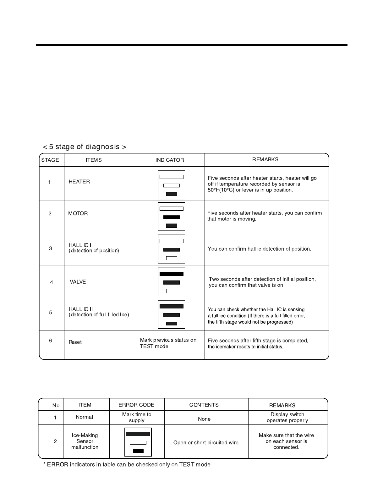
7-2-5 Function TEST
1. This is a compulsory operation for test, service, cleaning, etc. It is operated by pressing and holding the fill key for 3 seconds.
2. The test works only in the icemaking mode. It cannot be entered from the harvest or fill mode. (If there is an ERROR, it
can only be checked in the test mode.)
3. Caution! If the test is performed before water in the icemaker is frozen, the ejector will pass through the water. When the
fill mode begins (stage 4), unless the water supply has been shut off, added water will overflow into the ice bin. If the
control doesn’t operate normally in the test mode, check and repair as needed.
4. After water is supplied, the normal cycle is followed: icemaking → harvest → fill → park position.
5. Five seconds after stage 5 is completed, the icemaker returns to MICOM control. The time needed to supply water resets
to the pre-test setting.
7-3 DEFECT DIAGNOSIS FUNCTION
7-3-1 ERROR CODE on water supply control panel at Ice Maker
- 28 -

8-1 FUNCTION
8-1-1 Function
1. When the appliance is plugged in, it is set to “37” for Refrigerator and “0” for freezer.
You can adjust the Refrigerator and the Freezer control temperature by pressing the ADJUST button.
2. When the power is initially applied or restored after a power failure, it is automatically set to “37” & “0”.
8-1-2 How to Change the Temperature Mode to °F / °C
1. The setting temperature mode can be changed to °F / °C by pressing and holding Freezer Temp. key of Freezer and
Refrigerator Temp. key of Refrigerator over 5 seconds. at the same time.
2. The initial setting is °F. Whenever the mode is changed, the LCD lights are changed.
8-1-3 Lock function (dispenser and display button lock)
1. In power application of refrigerator, the “LOCK” icon is turned off at the
upper side of lock graphic of display with the lock release status.
2. If desiring to lock the display the dispenser and control panel push on
the LOCK button more than 3 seconds. LOCK text is turned on at the
upper side of lock graphic of display with lock status.
3. The buzzer sound and control panel and dispenser function is not
performed even if pressing display button other than lock key in the
lock status.
4. If desiring to release the lock status and pressing the lock button more
than 3 seconds. “LOCK” icon is turned off at the upper side of lock graphic of display with the lock release status.
8-1-4 Filter condition display function
1. There is a replacement indicator icon for the water
filter cartridge on the dispenser.
2. Water filter needs replacement once six months.
3. Water filter icon turns on to tell you need to replace
the filter soon.
4. After replace the filter, press and hold the lock button
more than 3 seconds.
Then water filter light turns off with reset status.
8-1-5 Ultra Ice selection
Please select this function for prompt freezer.
• Function is repeated following below whenever pressing Ultra Ice button.
• Ultra Ice function automatically turns off if a fixed time passes.
- 29 -
8. DESCRIPTION OF FUNCTION & CIRCUIT OF MICOM
Ex) In selecting
"LOCK"
Ex) In selecting
"LOCK" again
In initial Power On
/ Filter RESET
Replace indicator
light on
Classification
Filter Status
Display

8-1-6 CONTROL OF FREEZER FAN MOTOR
1. Freezer fan motor has high and standard speeds.
2. High speed is used at power-up, for Ultra Ice, and when refrigerator is overloaded.
Standard speeds is used for general purposes.
3. To improve cooling speed, the RPM of the freezer fan motor change from normal speed to high.
4. High speed (2700RPM) : Initial power on or load corresponding operation, Ultra Ice.
Normal speed (2400RPM) : General working conditions.
5. Fan motor stops when refrigerator or freezer door opens.
8-1-7 Ultra Ice
1. The purpose of this function is to intensify the cooling speed of freezer and to increase the amount of ice.
2. When Ultra Ice is selected, LCD will remain ON for Ultra Ice Cycle.
3. If power is lost to the refrigerator, Ultra Ice function will be canceled.
4. To activate this function, to press the Ultra Ice key and the LCD will turn ON. This function will remain activated for 24 hrs.
The first three hours the compressor and Freezer Fan will be ON. The next 21 hours the freezer will be controlled at the
lowest temperature. After 24 hours or if the Ultra Ice key is pressed again, the freezer will return to its previous
temperature.
5. For the first three hours notice the following cases:
(1) Compressor and freezer fan (HIGH RPM) continuously operate for three hours.
(2) If defrost starts during Ultra Ice, Ultra Ice operates for the rest of time after defrost is completed, when Ultra Ice
operation time is less than 90 minutes.
If Ultra Ice operates for more than 90 minutes, the Ultra Ice will operate for two hours after defrost is completed.
(3) If Ultra Ice is pressed during defrost, Ultra Ice LCD is on but this function will start seven minutes after defrost is
completed and it shall operate for three hours.
(4) If Ultra Ice is selected within seven minutes after compressor has stopped, the compressor (compressor delays seven
minutes) shall start after the balance of the delay time.
(5) The fan motor in the freezer compartment runs at high speed during Ultra Ice .
6. For the rest of the 21 hours, the freezer will be controlled at the lowest temperature.
8-1-8 REFRIGERATOR LAMP AUTO OFF
1. To avoid heat damage caused by the lamp, it is turned off automatically when the refrigerator door is open for more than 7
minutes.
8-1-9 Alarm for Open Door
1. This feature sounds a buzzer when the freezer or refrigerator door is not closed within 1 minute after it is opened.
2. One minute after the door is opened, the buzzer sounds three times each for 1/2 seconds. These tones repeat every 30
seconds.
3. The alarm is cancellcd when the freezer or the refrigerator is closed while the buzzer sounds.
- 30 -
Closed Open Closed Open
3 Times 3 Times 3 Times 3 Times
Closed
Within 1 min. 1 min.
30 sec 30 sec 30 sec
Freezer Door
or Refrigerator
Door
Buzzer

8-1-10 Buzzer Sound
When the button on the front Display is pushed, a Ding~ Dong~ sound is produced.
8-1-11 Defrost cycle
1. A defrost cycle will be initiated after 4 hours of accumulated compressor run time after the initial power up or a power
failure.
2. After the initial defrost, the defrost cycle is initiated after 7 hours of accumulated compressor run time.
3. The defrost cycle will be terminated once the defrost sensor reaches 50°F(10°C).
8-1-12 Filter Replacement Indication
1. After 6 months since the UNIT (refrigerator) has been power on, the water filter icon is ON.
2. When the water filter indicator LCD is illuminated, you should change the water filter. After this, you must press the water
filter button for three seconds and you will hear a ding-dong sound.
The icon will be OFF. This operation will indicate that the UNIT is reset to its initial conditions, so this process is restarted.
8-1-13 DISPENSER LIGHT
Please select this function for DISPENSER LIGHT MODE.
1. Normal status (LIGHT icon is OFF) : When dispenser is operated, DISPENSER LIGHT is ON.
2. ON status (LIGHT icon is ON) : DISPENSER LIGHT is on continuously.
- 31 -

- 32 -
8-1-13 Automatic Diagnosis Function
1. Automatic diagnosis makes servicing the refrigerator easy.
2. When an error occurs, the buttons will not operate; but the tones. such as ding. will sound.
3. When the error CODE removes the sign, it returns to normal operation (RESET).
4. The error CODE shows on the Refrigerator and Freezer Display.
ERROR CODE on display panel
✽ LCD check function: If simultaneously pressing Ultra Ice button and freezing temperature adjustment button
for a second, display LCD graphics on. If releasing the button, the LCD graphic displays
the previous status.

8-1-14 TEST Mode
1. The Test mode allows checking the PCB and the function of the components as well as finding out the defective part in
case of an error.
2. While in the test mode, the function control button is not recognized, but the recognition tone (beep~) sounds.
3. After exiting the test mode, be sure to reset by unplugging and then plugging in the appliance.
4. If an error, such as a sensor problem, is detected while in the test mode, the test mode is cleared and the error code is
displayed.
5. While an error code is displayed, the test mode will not be activated.
* Freezer Fan RPM Variable Check:
In case the freezer fan is in operation when the Ultra Ice button and freezing temp. button. Control are pressed for more
than one second at the same time freezer fan RPM changes. (for example if high speed, to normal speed or if normal
speed, to high speed for 30 seconds)
After 30 seconds, it turns to its original RPM.
* Demonstration MODE:
1. After open the door, when the Ultra Ice button and the Refrigerator Temperature Control button are pushed at the same
time and hold for 5 seconds or longer, it converts to Demonstration Mode.
2. The Display shows OFF in F/R temperature display.
3. In this status, all Loads are off (Compressor / Fan / Damper / Heater)
(The refrigerator Lamp automatic off function warks normally and can be demonstrated)
4. To release demonstration mode, reset display by pressing the Ultra Ice button and the Refrigerator Temperature Control
button at the same time and holding for 5 seconds or longer in status of open the door.
- 33 -
8-2 PCB FUNCTION
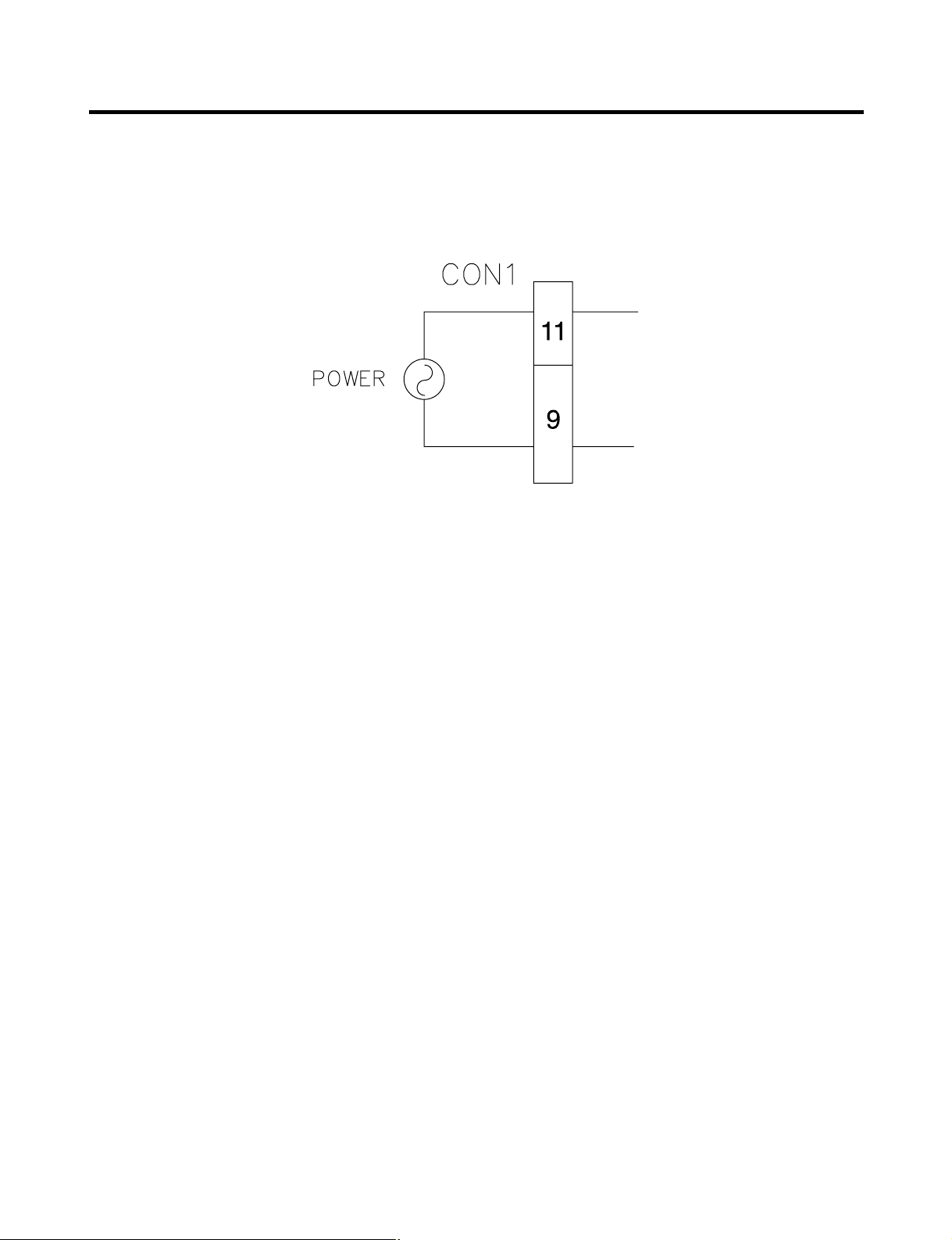
8-2-1 Power Circuit
1. Power is supplied to the control board at pin7 and 9 of connector #1.
- 34 -

8-2-2 Load / Buzzer Drive & Open Door Detection Circuit
1. Load Drive Condition Check
To measure outputs of the control board, check voltages between the pins for the following components:
NOTE: When the door of the freezer/refrigerator is left open for 7 minutes or longer, the lamp of the
freezer’refrigerator turns.
2. Fan motor driving circuit (freezing compartment fan, mechanical room)
- 35 -
F-FAN C-FAN
Pin Number Pin1 & 2 of con4 Pin4 & 5 of con4
MOTOR OFF 2V or less 2V or less
MOTOR ON 2V or less 2V or less
Circuit Pin Number Pin Number Output Voltage
Compressor Con1 pin1 Con1 pin1 115 VAC
Defrost heater Con2 pin1 Con1 pin1 115 VAC
F,R-lamp Con2 pin,3.5 Con1 pin1 115 VAC
Water valve Con2 pin7 Con1 pin1 115 VAC
Dew heater Con3 pin3 Con1 pin1 115 VAC
Water valve Con3 pin1 Con1 pin1 115 VAC

3. Open Door Detection Circuit Check
8-2-3 Temperature Sensor Circuit
• The resistance of the SENSOR has a ±5% common difference.
• Measure the resistance of the SENSOR after leaving it for over 3 minutes in the measuring temperature.
This delay is necessary due to sensor response speed.
- 36 -
Closed 0 V
Open 5 V
Freezer/
Refrigerator Door
Measurement
Location
Pin 4 & 5 of con4 Ref.Door
Pin 5 & 6 of con5 Fre.Door
TEMPERATURE
RESISTANCE OF FREEZER
RESISTANCE OF REFRIGERATOR &
SENSOR
DEFROST SENSOR & ROOM SENSOR
- 20 ˚C (-4 °F) 22.3 KΩ 77 KΩ
- 15 ˚C (5 °F) 16.9 KΩ 60 KΩ
- 10 ˚C (14 °F) 13.0 KΩ 47.3 KΩ
- 5 ˚C (23 °F) 10.1 KΩ 38.4 KΩ
0 ˚C (32 °F) 7.8 KΩ 30 KΩ
+ 5 ˚C (41 °F) 6.2 KΩ 24.1 KΩ
+ 10 ˚C (50 °F) 4.9 KΩ 19.5 KΩ
+ 15 ˚C (59 °F) 3.9 KΩ 15.9 KΩ
+ 20 ˚C (68 °F) 3.1 KΩ 13 KΩ
+ 25 ˚C (77 °F) 2.5 KΩ 11 KΩ
+ 30 ˚C (86 °F) 2.0 KΩ 8.9 KΩ
+ 40 ˚C (104 °F) 1.4 KΩ 6.2 KΩ
+ 50 ˚C (122 °F) 0.8 KΩ 4.3 KΩ
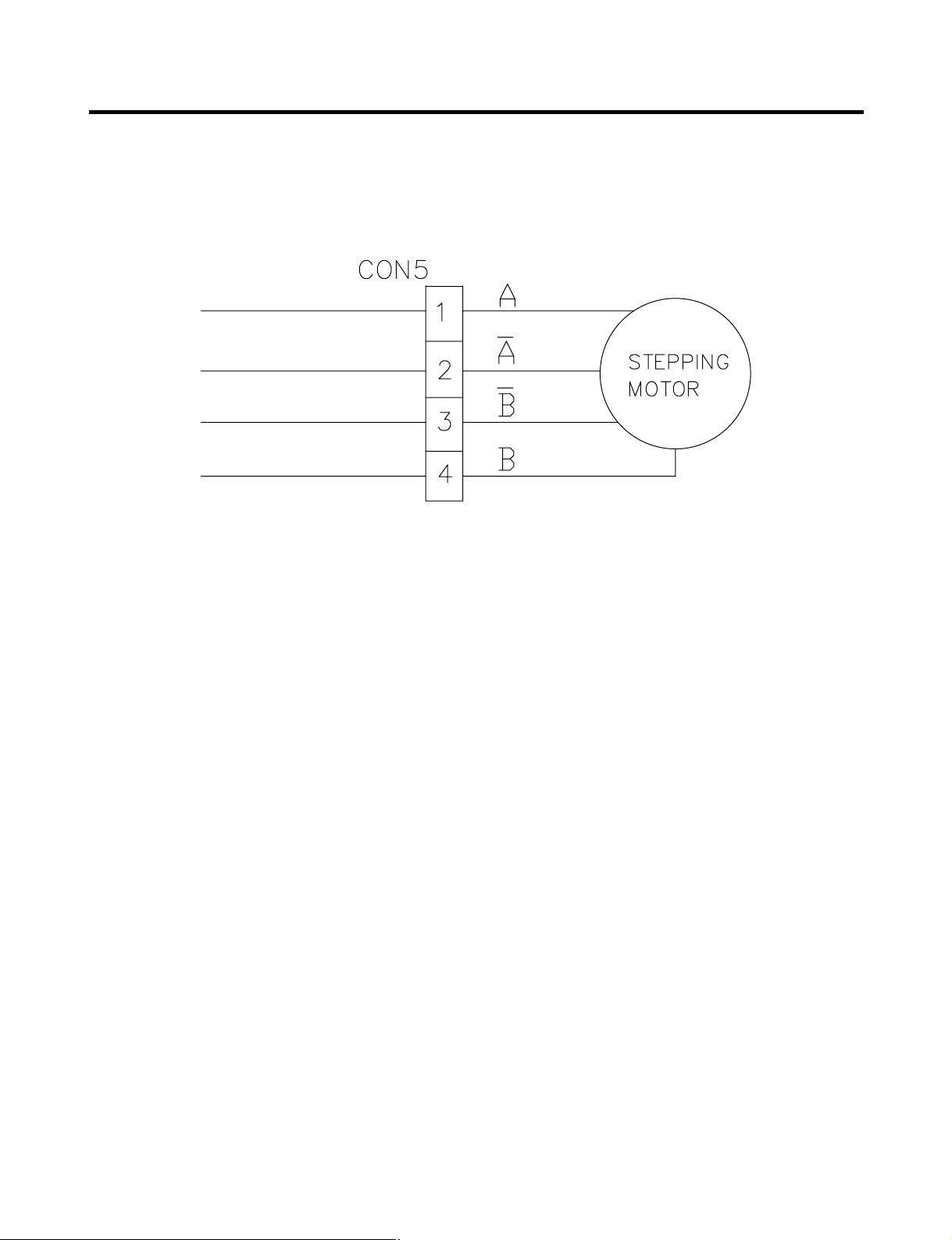
8-2-4 Refrigeration Compartment Stepping Motor Damper Circuit
A reversible DC motor is used to open and close the damper.
To open the damper, push test button once.
To close the damper, push test button twice.
- 37 -

8-3 TROUBLESHOOTING
- 38 -
PROBLEM INDICATED BY CHECK CHECKING METHOD CAUSE SOLUTION
POWER
SOURCE is
poor.
COOLING is
poor.
1. The whole
DISPLAY LCD is
off.
2. DISPLAY LCD
DISPLAY
operates
abnormally
NO COOLING.
FREEZER
TEMPERATURE
is incorrect
1. FREEZER/
REFRIGERAT OR.
2. If LAMP is dim.
3. The connection of the
MAIN PWB
CONNECTOR.
1. If the COMPRESSOR
operate.
2. If refrigerant is leaking.
1. If FAN MOTOR
operates.
2. If DEFROSTING is
normal.
3. If SENSOR is normal.
4. Door Line contact.
Check if
FREEZER/REFRIGERA
TOR DOOR IS OPEN
and check display .
Check visually.
Check connection of
CONNECTOR.
USE TEST MODE1
(forced COOLING).
If less than 7 minutes
pass after compressor
shuts off, don’t press the
KEY and wait.
Measure the amount of
frost sticking on
EV APORA TOR and the
surface temperature of
the condenser pipe.
USE TEST MODE1
(forced COOLING).
Check the amount of frost
sticking on the
EV APORA TOR .
of the Refrigerator
SENSOR.
Check the seal when the
door is closed.
POWER SOURCE is
poor.
Applied voltage error.
CONNECTOR
connection is poor.
TRANS FUSE is open.
COMPRESSOR locked
or blocked.
OLP , PTC is poor .
COMPRESSOR RELA Y
is poor.
THE CONNECTING
WIRE is poor.
Refrigerant leakage.
FAN MOTOR is poor .
CONNECTING WIRE is
poor.
DEFROSTING is poor.
SENSOR RESIST ANCE
is poor.
Door liner damaged.
Use boosting TRANS.
Reconnect
CONNECTOR.
Replace TRANS.
Replace
COMPRESSOR.
Replace OLP , PTC.
Replace MAIN PWB.
Check the connection of
the black wire of the
MAIN PWB
CONNECTOR (CON2).
Replace the leaking part
and replace any lost
refrigerant.
Replace the FAN
MOTOR.
Certify the MOTOR and
the connection of the
black wire of the MAIN
PWB CONNECTOR
(CON2).
See DEFROSTING is
poor.
Replace SENSOR.
Replace door liner.

- 39 -
PROBLEM INDICATED BY CHECK CHECKING METHOD CAUSE SOLUTION
COOLING is
poor.
DEFROSTIN
G is poor.
If
REFRIGERA TOR
TEMPERATURE
is too low.
NO
DEFROSTING.
1. If FREEZER
TEMPERATURE is
normal.
2. If amount of cool air
from FAN MOTOR is
sufficient.
3. Door Line contact.
1. If HEATER emits heat.
2. If DRAIN PIPE is
blocked.
3. If ice remains after
DEFROSTING.
Check is FREEZER
TEMPERATURE is too
low.
Make sure that the
amount and speed of cool
air are sufficient by
touching the check
supplied on the
REFRIGERA TOR.
Check door seal when
door is closed.
USE TEST MODE3
(forced DEFROSTING).
Check DRAIN PIPE.
Make sure that
DEFROST SENSOR is
connected.
Make sure that
FREEZER
/REFRIGERA TOR
DOOR is closed.
FAN MOTOR is poor .
Passage of cool air is
blocked.
EV A frozen.
Door liner damaged.
HEATER disconnection.
TEMPERATURE FUSE
disconnection.
Connection is poor.
DEFROST-SENSOR is
poor.
HEATER RELAY is poor.
DRAIN PIPE is blocked.
Connection is poor.
DOOR does not close
properly .
Make sure the DOOR
isattached.
Replace FAN MOTOR.
Remove impurities.
See DEFROSTING is
poor.
Replace Door liner.
Replace HEATER.
Replace
TEMPERATURE FUSE.
Check EVAPORATOR
connection and wire of
MAIN PWB
CONNECTOR.
Replace DEFROSTSENSOR.
Replace RY3 of MAIN
PWB.
Remove ice and
impurities.
Check HEATER PLATE
resistance.
Reassemble the
DEFROST-SENSOR.
Reassemble DOOR.
Replace GASKET .

8-4 MAIN PWB ASSEMBLY AND PARTS LIST
8-4-1 Main PWB Assembly
- 40 -
Connector4
Connector1
Connector3 Connector2
Connector6
T est Switch
Connector5

® Registered Trademark / TM Trademark /
SM
Service Mark of Sears, Roebuck and Co.
® Marca Registrada /
TM
Marca de Fábrica / SM Marca de Servicio de Sears, Roebuck and Co.
MC
Marque de commerce / MD Marque déposée de Sears, Roebuck and Co. © Sears, Roebuck and Co.
Get it fixed, at your home or ours!
Your Home
For repair – in your home – of all major brand appliances,
lawn and garden equipment, or heating and cooling systems,
no matter who made it, no matter who sold it!
For the replacement parts, accessories and
owner’s manuals that you need to do-it-yourself.
For Sears professional installation of home appliances
and items like garage door openers and water heaters.
1-800-4-MY-HOME
®
(1-800-469-4663)
Call anytime, day or night
(U.S.A. and Canada)
www.sears.com www.sears.ca
Our Home
For repair of carry-in items like vacuums, lawn equipment,
and electronics, call or go on-line for the location of your nearest
Sears Parts & Repair Center.
1-800-488-1222
Call anytime, day or night (U.S.A. only)
www.sears.com
To purchase a protection agreement (U.S.A.)
or maintenance agreement (Canada) on a product serviced by Sears:
1-800-827-6655 (U.S.A.) 1-800-361-6665 (Canada)
Para pedir servicio de reparación
a domicilio, y para ordenar piezas:
1-888-SU-HOGAR
SM
(1-888-784-6427)
Au Canada pour service en français:
1-800-LE-FOYER
SM
(1-888-533-6937)
www.sears.ca
The model number of your
refrigerator is found on the serial
plate inside.
All repair parts listed are available
for immediate purchase or special
order when you visit your nearest
Sears Service Center, or the
Service Department at most Sears
stores. To order parts by phone,
call the toll free parts number
listed to the left.
When requesting service or
ordering parts, always provide the
following information:
•Product Type •Part Number
•Model Number •Part Description
To call
Toll Free
For Parts:
1-800-366-PART
(1-800-366-7278)
For Service:
1-800-4-MY-HOME
(1-800-469-4663)
MODELS No.
795.77729700
795.77719700
795.77713700
795.77712700
REPAIR
PAR TS
LIST
Sears, Roebuck and Co., Hoffman Estates, IL 60179 U.S.A.
602A
S13
600A
616F
623B
616H
S31
625A
S31
S31
627A
616E
623A
627B
619D
616C
616D
S31
S31
S30
S31
617A
623B
616H
603A
616F
619A
619B
S32
603B
MAY. 14. 2007
616K
600B
- 1 -
Part No. MBM39026801
CAUTION: Use the part number to order part, not the location number.
ICE MAKER PARTS
LOC No. 777* Description
600A 5989JA0002Q ICEMAKERASSEMBLY,KIT
600B 4510JA2014A LEVER,ICE MAKER
602A 4930JA3090A HOLDER,BRACKET
603A 4930JA3093B HOLDER,BRACKET
603B 4930JA3091A HOLDER,BRACKET
616C 5210jJA3004U TUBE,PE
616D 5210JA3005Q TUBE,PE
616E 5211JA3003E TUBEASSEMBLY,INJECT
616F 5210JA3004R TUBE,PE
616H 4932JA3002C CONNECTOR(MECH),TUBE
616K 5210JJ3007B TUBE, INJECT
617A 4970JA3004N SPRING,W
619A 5221JB1004N VALVE ASSEMBLY,WATER
619B 5221JB2006K VALVE ASSEMBLY,WATER
619D 6877JK2014B DRAWING,ASSEMBLY
623A 4770JA3001A BAND(MECH)
623B 5006JJ2009A CAP,COVER
625A 3550JA2184A COVER,TUBE
627A 4930JJ3018A HOLDER,PIPE
627B 4930JA3054A HOLDER,PIPE
S13 1SZZJJ3005E SCREW,DRAWING
S30 1SZZJJ3009A SCREW,DRAWING
S31 4J00415D SCREW,DRAWING
S32 4000W4A003A SCREW,DRAWING

- 2 -
316A
316B
607A
624A
624C
624D
626A
106A
315A
400A
501A
411A
501F
303C
318A
303B
314A
300A
312A
317A
304A
103A
S02
S01
S01
105A
283B
283B
328A
207B
103B
207A
315B
315B
315C
315C
323B
329C
420A
309B
319A
319C
408A
503D
410A
409D
409B
158A
405F
404A
405C
332A
135D
405A
S16
B03
B04
S17
S15
158B
145B
B03
409B
106A
406D
610A
610A
406A
405B
329A
103C
135C
402A
402A
410G
406B
S10
S11
S13
S11
S19
S20
S18
S02
B01
S03
S03
B01
S11
S14
262B
B02
B02
S14
262H
610D
610B
301A
S18
313A
249D
249C
610C
CASE PARTS
CAUTION: Use the part number to order part, not the position number.
120B
145A
282G
282F
120A
271A
271B
271C
271D

- 3 -
CASE PARTS
L/No. 77729 77719 77712 77713 Descrption
103A 3650JA2113P 3650JA2113P 3650JA2061B 3650JA2061X Handle,Rear
103B 3650JA2113N 3650JA2113N 3650JA2061A 3650JA2061W Handle,Rear
103C 3550JJ0008C 3550JJ0008C 3550JJ0008A 3550JJ0008L Cover,Lower
105A 5251JA3003B 5251JA3003B 5251JA3003B 5251JA3003B Tube Assembly,Drain
106A 4779JJ2001B 4779JJ2001B 4779JJ2001B 4779JJ2001B Leg Assembly,Adjust
120A 5209JJ1009A 5209JJ1009A 5209JJ1009A 5209JJ1009A Duct Assembly,Multi
135C 3550JA2263A 3550JA2263A 3550JA2263A 3550JA2263A Cover,Grille Fan
135D 3551JJ2028A 3551JJ2028A 3551JJ2028A 3551JJ2028A Cover Assembly,Grille Fan
145A 4930JA2080C 4930JA2080C 4930JA2080C 4930JA2080C Holder,Shelf
145B 4930JA2081C 4930JA2081C 4930JA2081C 4930JA2081C Holder,Shelf
158A 3550JJ1070B 3550JJ1070B 3550JJ1070B 3550JJ1070B Cover,Lamp
158B 3550JA1386B 3550JA1386B 3550JA1386B 3550JA1386B Cover,Lamp
207A 3550JJ1097E 3550JJ1097E 3550JJ1097A 3550JJ1097Q Cover,Hinge
207B 3550JJ1097F 3550JJ1097F 3550JJ1097B 3550JJ1097R Cover,Hinge
249C 4930JA1068B 4930JA1068B 4930JA1068B 4930JA1068B Holder,Rail
249D 4930JA1068A 4930JA1068A 4930JA1068A 4930JA1068A Holder,Rail
262B 4775JJ2017F 4775JJ2017F 4775JJ2017B 4775JJ2017P Hinge Assembly,Center
262H 4775JJ2017H 4775JJ2017H 4775JJ2017D 4775JJ2017R Hinge Assembly,Center
271A 4775JJ2014B 4775JJ2014B 4775JJ2014B 4775JJ2014B Hinge Assembly,Upper
271B 4510JA3004A 4510JA3004A 4510JA3004A 4510JA3004A Lever,Hinge
271C 4775JJ2014A 4775JJ2014A 4775JJ2014A 4775JJ2014A Hinge Assembly,Upper
282F 3806JL1037A 3806JL1037A 3806JL1037A 3806JL1037A Decor,Duct
283B 4774JJ3002A 4774JJ3002A 4774JJ 3002A 4774JJ3002A Hinge,Lower
300A 2521JA1020C 2521JA1020C 2521JA1020C 2521JA1020C Compressor,Assembly
301A 5421JJ1003B 5421JJ1003B 5421JJ1003B 5421JJ1003B Evaporator Assembly
303B 6748JA3001C 6748JA3001C 6748JA3001C 6748JA3001C Thermistor,PTC
303C 6750JA3001C 6750JA3001C 6750JA3001C 6750JA3001C Overload Protect
304A 3550JA2158A 3550JA2158A 3550JA2158A 3550JA2158A Cover,PTC
308A 3551JA2081D 3551JA2081D 3551JA2081D 3551JA2081D Cover Assembly,PTC
309B 5040JJ2001A 5040JJ2001A 5040JJ2001A 5040JJ2001A Damper,Motor Support
312A 5040JA3071A 5040JA3071A 5040JA3071A 5040JA3071A Damper,Compressor
313A 3551JJ2018A 3551JJ2018A 3551JJ2018A 3551JJ2018A Cover Assembly,Machinery(Rear)
314A 4620JA3015A 4620JA3015A 4620JA3015A 4620JA3015A Stopper,Compressor
315A 3103JJ1001H 3103JJ1001H 3103JJ1001H 3103JJ1001H Base Assembly,Compressor
315B 4580JJ3001A 4580JJ3001A 4580JJ3001A 4580JJ3001A Roller
315C 1PZZJA3013B 1PZZJA3013B 1PZZJA3013B 1PZZJA3013B Pin,Common
316A 5072JA3003F 5072JA3003F 5072JA3003F 5072JA3003F Damper,Noise
316B 5072JA3003B 5072JA3003B 5072JA3003B 5072JA3003B Damper,Noise
317A 5851JA2008U 5851JA2008U 5851JA2008U 5851JA2008U Drier Assembly
318A 4930JA3034A 4930JA3034A 4930JA3034A 4930JA3034A Holder,Drier
319A 3390JA0040A 3390JA0040A 3390JA0040A 3390JA0040A Tray,Drip
319C 4974JJ1036A 4974JJ1036A 4974JJ1036A 4974JJ1036A Guide,Fan
323B 5403JJ1004B 5403JJ1004B 5403JJ1004B 5403JJ1004B Condenser Assembly,Wire
327A 4J03020A 4J03020A 4J03020A 4J03020A Damper,Pipe
329A 5901JA1021A 5901JA1021A 5901JA1021A 5901JA1021A Fan Assembly
329C 5901JA1013A 5901JA1013A 5901JA1013A 5901JA1013A Fan Assembly
332A 3530JJ0007A 3530JJ0007A 3530JJ0007A 3530JJ0007A Grille,Fan
400A 6615JB2005H 6615JB2005H 6615JB2005H 6615JB2005H Controller Assembly
402A 6600JB3007E 6600JB3007E 6600JB3007A 6600JB3007B Switch,Push Button
402A 6600JB3007E 6600JB3007E 6600JB3007A 6600JB3007B Switch,Push Button
404A 4681JK1004D 4681JK1004D 4681JK1004D 4681JK1004D DC Motor
405A 4810JJ0003A 4810JJ0003A 4810JJ0003A 4810JJ0003A Bracket,Motor
405B 4810JJ2005A 4810JJ2005A 4810JJ2005A 4810JJ2005A Bracket,Motor
405C 5040JA2009B 5040JA2009B 5040JA2009B 5040JA2009B Damper,Motor Support
405F 5040JA2004B 5040JA2004B 5040JA2004B 5040JA2004B Damper,Motor Support
406A AEJ33488901 AEJ33488901 AEJ33488901 AEJ33488901 Holder Assembly,Bracket
406B 6600JB1010A 6600JB1010A 6600JB1010A 6600JB1010A Switch,Push Button
406D 4931JA3006A 4931JA3006A 4931JA3006A 4931JA3006A Holder Assembly,Gasket
408A 5300JK1005D 5300JK1005D 5300JK1005D 5300JK1005D Heater,Sheath
409B 6912JB2004K 6912JB2004K 6912JB2004K 6912JB2004K Lamp,Incandescent
409D 3034JA1009A 3034JA1009A 3034JA1009A 3034JA1009A Reflector,Lamp
410A 6621JK2003B 6621JK2003B 6621JK2003B 6621JK2003B Drawing,Assembly
410G 0CZZJB2012J 0CZZJB2012J 0CZZJB2012J 0CZZJB2012J Capacitor,Electric Appliance Film,Box
411A 6411JK1006A 6411JK1006A 6411JK1006A 6411JK1006A Power Cord Assembly
420A 4681JB1029D 4681JB1029D 4681JB1029D 4681JB1029D Motor,DC
501A 6871JB1423G 6871JB1423G 6871JB1423G 6871JB1423G PCB Assembly,Main
501F 3551JA2144A 3551JA2144A 3551JA2144A 3551JA2144A Cover Assembly,PCB
503D 3110JJ1014A 3110JJ1014A 3110JJ1014A 3110JJ1014A Case,Lamp
607A 4931JA3005B 4931JA3005B 4931JA3005B 4931JA3005B Holder Assembly,Bracket
610A 3550JA2247A 3550JA2247A 3550JA2247A 3550JA2247A Cover,Sensor
610B 6500JB1001K 6500JB1001K 6500JB1001K 6500JB1001K Sensor,Temperature
610C 6500JB2002B 6500JB2002B 6500JB2002B 6500JB2002B Sensor
610D 6500JB2001B 6500JB2001B 6500JB2001B 6500JB2001B Sensor
624A 5231JA2006A 5231JA2006A 5231JA2006A 5231JA2006A Filter Assembly,Water
624C 3550JD1128B 3550JD1128B 3550JD1128B 3550JD1128B Cover,Filter
624D 5230JA2003A 5230JA2003A 5230JA2003A 5230JA2003A Filter,Head
626A 3550JA2279A 3550JA2279A 3550JA2279A 3550JA2279A Cover,Filter
B01 4000W4A003A 4000W4A003A 4000W4A003A 4000W4A003A Screw,Customized
B02 1STZJA3004Q 1STZJA3004Q Screw,Customized
B03 1STZJA3004F 1STZJA3004F Screw,Customized
B04 1BZZJA2002A 1BZZJA2002A Bolt,Common
CAUTION: Use the part number to order part, not the position number.

- 4 -
145C
250C
250D
136B
145F
250D
136A
237C
131A
250E
250C
CAUTION: Use the part number to order part, not the position number.
L/No. 777* Descrption
131A 5074JA2008A Bucket,Ice
136A 3390JJ1073A Tray,Drawer
136B 3391JA1114B Tray Assembly,Drawer
145C 4975JA1040D Guide Assembly,Rail
145F 4975JA1040C Guide Assembly,Rail
237C 4974JJ1032A Guide,Drawer
250C 4470JA2008A Gear,Ice
250D 5006JA2069A Cap,Cover
250E MAK36519001 Bar
FREEZER PARTS
CAUTION: Use the part number to order part, not the position number.
CASE PARTS
S01 4J00415D 4J00415D 4J00415D 4J00415D Screw,Customized
S02 4J00415D 4J00415D 4J00415D 4J00415D Screw,Customized
S03 4J00415D 4J00415D 4J00415D 4J00415D Screw,Customized
S08 1SZZJJ3005Z 1SZZJJ3005Z 1SZZJJ3005Z 1SZZJJ3005Z Screw,Customized
S10 1SBZJA3004L 1SBZJA3004L 1SBZJA3004L 1SBZJA3004L Screw,Customized
S11 3J05696W 3J05696W 3J05696W 3J05696W Screw,Customized
S12 3J05696W 3J05696W 3J05696W 3J05696W Screw,Customized
S13 1SZZJJ3005E 1SZZJJ3005E 1SZZJJ3005E 1SZZJJ3005E Screw,Customized
S14 1SZZJJ3010D 1SZZJJ3010D 1SZZJJ3010D 1SZZJJ3010D Screw,Customized
S15 4000W4A003A 4000W4A003A 4000W4A003A 4000W4A003A Screw,Customized
S16 3J05696W 3J05696W 3J05696W 3J05696W Screw,Customized
S17 1SZZJA3005H 1SZZJA3005H 1SZZJA3005H 1SZZJA3005H Screw,Customized
S18 4J00415D 4J00415D 4J00415D 4J00415D Screw,Customized
S19 4J00415D 4J00415D 4J00415D 4J00415D Screw,Customized
S20 1SZZJA3016A 1SZZJA3016A 1SZZJA3016A 1SZZJA3016A Screw,Customized
L/No. 77729 77719 77712 77713 escrption
145G
145J
145M
145J
145H
145K

- 5 -
141B
141C
141A
141B
141C
141A
141B
141C
141A
141B
141C
141A
147C
147B
147A
145E
248H
162B
145D
162A
160C
155J
146B
154A
151A
151C
167B
S13
S13
161A
161C
161F
161E
161A
161D
141D
REFRIGERATOR PARTS
CAUTION: Use the part number to order part, not the position number.
*
: on some models

- 6 -
REFRIGERATOR PARTS
L/No. 77729 77719 77712 77713 Descrption
141A 5027JJ2014C 5027JJ2014C 5027JJ2014C 5027JJ2014C Shelf Assembly,Refrigerator
141B 5026JJ1051B 5026JJ1051B 5026JJ1051B 5026JJ1051B Shelf,Refrigerator
141C 5027JJ2012E 5027JJ2012E 5027JJ2012E 5027JJ2012E Shelf Assembly,Net
141D 4890JL1012B 4890JL1012B 4890JL1012B 4890JL1012B Cover,Glass
145D 3391JJ1030B 3391JJ1030B 3391JJ1030B 3391JJ1030B Tray Assembly,Fresh Room
145E 3550JL1011B 3550JL1011B 3550JL1011B 3550JL1011B Cover,Tray
146A J469-00030A Rack
146B 4520JJ1004A 4520JJ1004A 4520JJ1004A 4520JJ1004A Link
147A 5074JJ1016A 5074JJ1016A 5074JJ1016A 5074JJ1016A Bucket,Dairy
147B 3390JJ1082A 3390JJ1082A 3390JJ1082A 3390JJ1082A Tray,Egg
147C 3550JJ1084A 3550JJ1084A 3550JJ1084A 3550JJ1084A Cover,Bucket
151A 3391JJ2014A 3391JJ2014A 3391JJ2014A 3391JJ2014A Tray Assembly,Vegetable
151C 4940JA2026C 4940JA2026C 4940JA2026C 4940JA2026C Knob,Shutter
154A 3550JL1017A 3550JL1017A 3550JL1017A 3550JL1017A Cover,TV
154B 3551JJ2031B 3551JJ2031B 3551JJ2031B 3551JJ2031B Cover Assembly,TV
155J 4940JJ2009B 4940JJ2009B 4940JJ2009B 4940JJ2009B Knob,Shutter
160C 3551JJ2021A 3551JJ2021A 3551JJ2021A 3551JJ2021A Cover Assembly,Tray
161A 4930JJ1018A 4930JJ1018A 4930JJ1018A 4930JJ1018A Holder,Rail
161C 5218JA2004B 5218JA2004B 5218JA2004B 5218JA2004B Rail,Slide
161D 5218JA2004A 5218JA2004A 5218JA2004A 5218JA2004A Rail,Slide
161E 4975JJ2019D 4975JJ2019D 4975JJ2019D 4975JJ2019D Guide Assembly,Rail
161F 4975JJ2019C 4975JJ2019C 4975JJ2019C 4975JJ2019C Guide Assembly,Rail
162A 4975JJ2016A 4975JJ2016A 4975JJ2016A 4975JJ2016A Guide Assembly,Rail
162B 4975JJ2016B 4975JJ2016B 4975JJ2016B 4975JJ2016B Guide Assembly,Rail
167B 3550JJ1073A 3550JJ1073A 3550JJ1073A 3550JJ1073A Cover,Magic Room
248A 4980JJ2012B 4980JJ2012B 4980JJ2012B 4980JJ2012B Supporter,Holder
248H 4980JJ2014A 4980JJ2014A 4980JJ2014A 4980JJ2014A Supporter,Holder
S13 1SZZJJ3005E 1SZZJJ3005E 1SZZJJ3005E 1SZZJJ3005E Screw,Customized
S13 1SZZJJ3005E 1SZZJJ3005E 1SZZJJ3005E 1SZZJJ3005E Screw,Customized
DOOR PARTS
CAUTION: Use the part number to order part, not the position number.
L/No. 77729 77719 Descrption
204A MBL38083902 MBL38083902 Cap,Decor Refrigerator
204B 5079JA2193F 5079JA2193F Cap Assembly,Decor Refrigerator
206A 3806JA1196C 3806JA1196C Decor,Door
206B 3806JA1196D 3806JA1196D Decor,Door
206C MBL38083901 MBL38083901 Cap,Decor Refrigerator
206D 5079JA2193E 5079JA2193E Cap Assembly,Decor Refrigerator
206E 4890JA1142M 4890JA1142M Decor,Glass Door
206F 4890JA1143K 4890JA1143K Decor,Glass Door
206J 4890JA1100W 4890JA1100W Decor,Glass Door
220D 1TRL0302818 1TRL0302818 Screw,Tapping
220E 1SZZJA3009L 1SZZJA3009L Screw,Customized
230A ADC33795901 ADC33795901 Door Assembly,Refrigerator(Right)
230B 3581JA8808X 3581JA8808X Door Assembly,Refrigerator(Left)
231A ADD37795201 ADD37795201 Door Foam Assembly,Refrigerator
231B ADD33795601 ADD33795601 Door Foam Assembly,Refrigerator
233A 4987JJ2002C 4987JJ2002C Gasket Assembly,Door
233B 4987JJ2002D 4987JJ2002D Gasket Assembly,Door
233C 3551JJ2030B 3551JJ2030B Cover Assembly,Front
233D 3551JJ2030A 3551JJ2030A Cover Assembly,Front
234A 4430JJ2004A 4430JJ2004A Cam,Shaft
234B 4430JJ2004B 4430JJ2004B Cam,Shaft
234C 4931JJ2002C 4931JJ2002C Holder Assembly,Gasket
234D 4931JJ2002D 4931JJ2002D Holder Assembly,Gasket
237A 4974JA2055A 4974JA2055A Guide,Pitcher
241A 5004JL1006B 5004JL1006B Basket,Window
241B 5004JJ1057A 5004JJ1057A Basket,Door
241C 5005JJ2014A 5005JJ2014A Basket Assembly,Door
243A 4620JA3027C 4620JA3027C Stopper,Door
243B 4620JJ2009A 4620JJ2009A Stopper,Door
243C J326-00012A J326-00012A Bush
244C AED33696802 AED33696802 Handle Assembly
244B AED33711801 AED33711801 Handle Assembly,Decor
262C 4350JA3005B 4350JA3005B Ring
312B 3550JL1014A 3550JL1014A Cover,Front
312C 5006JA3016C 5006JA3016C Cap,Duct
615A 4838JA2002A 4838JA2002A Tank,Water
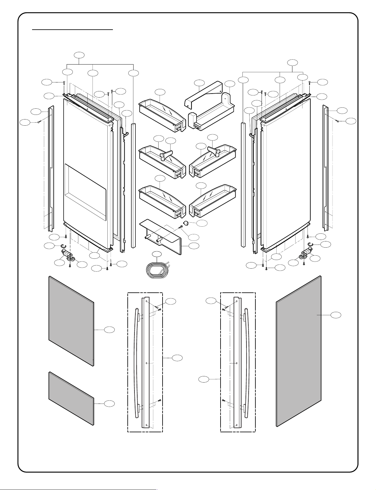
- 7 -
241C
237A
241C
241C
241A
241B
241C
237A
241C
312B
S26
615A
312C
233B 233C
234B
234D
230B
206A
220E
220D
220D
204A
206E
206F
243A
243B
262C
220D
204B
231B
206J
243A
243B
206D
262C
220D
233A233D
231A
230A
220D
206C
206B
220E
234C
234A
220D
220D
220E
220E
220D
220E
220E
220E
244C
244B
220E
DOOR PARTS (77719, 77729)
CAUTION: Use the part number to order part, not the position number.
276A=206A+206B+244B+244C+236A+236B
▲ Only for the service
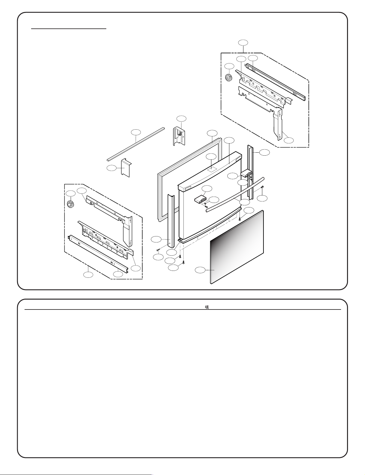
- 8 -
250A
205B
205C
203A
220D
220E
220E
220D
220E
201A
206H
236B
204C
236A
250B
249G
249E
249A
249J
249H
249F
249B
250B
249K
212G
212D
B06
B06
212F
212E
DOOR PARTS (77719, 77729)
CAUTION: Use the part number to order part, not the position number.
CAUTION: Use the part number to order part, not the position number.
L/No. 77729 77719 Descrption
200A 3581JA8817T 3581JA8817T Door Assembly, Freezer
201A ADD33795101 ADD33795101 Door Foam Assembly,Freezer
203A MDS38201402 MDS38201402 Gasket,Door
204C 5079JA2194C 5079JA2194C Cap Assembly,Decor Freezer
205B 5006JJ2013A 5006JJ2013A Cap,Cover
205C 5006JJ2013B 5006JJ2013B Cap,Cover
206H 4890JA1145L 4890JA1145L Decor,Glass Door
212D AED33696801 AED33696801 Handle Assembly
212E AEJ33686201 AEJ33686201 Holder Assembly,Handle
212F AEJ33686202 AEJ33686202 Holder Assembly,Handle
212G 3846JD1019A 3846JD1019A Name Plate
220D 1SZZJA3009L 1SZZJA3009L Screw,Customized
220E 1TCL0302818 1TCL0302818 Screw,Tapping
236A 3806JA1197C 3806JA1197C Decor,Door
236B 3806JA1197D 3806JA1197D Decor,Door
249A ACJ33058104 ACJ33058104 Connector Assembly
249B ACJ33058103 ACJ33058103 Connector Assembly
249E 5218JA1009E 5218JA1009E Rail,Slide
249F 5218JA1009F 5218JA1009F Rail,Slide
249G 3550JA1456A 3550JA1456A Cover,Connector
249H 3550JA1456B 3550JA1456B Cover,Connector
249J MCD38084202 MCD38084202 Connector,Rail
249K MCD38084201 MCD38084201 Connector,Rail
250A MAK39123901 MAK39123901 Bar
250B 4403JA3005A 4403JA3005A Connector Assembly
276A ACW35090301 ACW35090301 Decor Assembly,Door
B06 FAB30025702 FAB30025702 Screw,Customized
▲ Only for the service
276A=206A+206B+244B+244C+236A+236B

- 9 -
279A
293A
290A
291A
295A
403A
292A
294A
279C
616A
S27
279B
DISPENSER PARTS (77719, 77729)
CAUTION: Use the part number to order part, not the position number.
L/No. 77729 77719 Descrption
279A EBR36499201 EBR36499201 PCB Assembly,Display
279B MCK38084101 MCK38084101 Cover,Dispenser
279C MCR38202401 MCR38202401 Decor,Drain
290A 3550JA2280A 3550JA2280A Cover,PCB
291A 4890JD1112B 4890JD1112B Decor,Glass Door
292A 6871JB2074B 6871JB2074B PCB Assembly,Sub
293A 5021JA3020C 5021JA3020C Button Assembly
294A 4510JA2028A 4510JA2028A Lever,Dispenser
295A 6877JB2181A 6877JB2181A Drawing,Assembly
403A 6600JB3001B 6600JB3001B Switch,Micro
616A 5210JA2012E 5210JA2012E Tube,Inject
S27 4J00415D 4J00415D Screw,Customized
CAUTION: Use the part number to order part, not the position number.

- 10 -
233A233D
231A
233B 233C
231B
241C
237A
241C
241C
230B
241A
241B
241C
237A
241C
243A
243B
243C
203A
201A
212G
230A
312B
S25
S26
S25
243B
615A
262C
262C
243C
312C
244A
212D
244A
B06
B06
B05
B05
B05
B05
234B 234A
250A
205B
205C
250B
249G
249E
249A
249J
249H
249F
249B
250B
249K
DOOR PARTS (77712, 77713)
CAUTION: Use the part number to order part, not the position number.
▲ Only for the service

- 11 -
DOOR PARTS
CAUTION: Use the part number to order part, not the position number.
L/No. 77712 77713 Descrption
200A 3581JA8817W 3581JA8817V Door Assembly,Freezer
201A ADD34126202 ADD34126201 Door Foam Assembly,Freezer
203A MDS38201401 MDS38201401 Gasket,Door
205B 5006JJ2013A 5006JJ2013A Cap,Cover
205C 5006JJ2013B 5006JJ2013B Cap,Cover
212D 3651JA2279K 3651JA2279J Handle Assembly,Freezer
212G 3846JD1019A 3846JD1019A Name Plate
230A 3581JA8807H 3581JA8807M Door Assembly,Refrigerator(Right)
230B 3581JJ8051Q 3581JA8808Z Door Assembly,Refrigerator(Left)
231A 5433JJ0064F 5433JJ0064Q Door Foam Assembly,Refrigerator
231B 5433JA8559D 5433JA8559R Door Foam Assembly,Refrigerator
233A 4987JJ2002A 4987JJ2002A Gasket Assembly,Door
233B 4987JJ2002B 4987JJ2002B Gasket Assembly,Door
233C 3551JJ2030B 3551JJ2030B Cover Assembly,Front
233D 3551JJ2030A 3551JJ2030A Cover Assembly,Front
234A 4430JJ2004A 4430JJ2004A Cam,Shaft
234B 4430JJ2004B 4430JJ2004B Cam,Shaft
234C 4931JJ2002A 4931JJ2002A Holder Assembly,Gasket
234D 4931JJ2002B 4931JJ2002B Holder Assembly,Gasket
237A 4974JA2055A 4974JA2055A Guide,Pitcher
241A 5004JL1006B 5004JL1006B Basket,Window
241B 5004JJ1057A 5004JJ1057A Basket,Door
241C 5005JJ2014A 5005JJ2014A Basket Assembly,Door
243A 4620JJ3006A 4620JJ3006D Stopper,Door
243A 4620JJ3006A 4620JJ3006D Stopper,Door
243B 4620JJ2009A 4620JJ2009A Stopper,Door
243B 4620JJ2009A 4620JJ2009A Stopper,Door
243C J326-00012A J326-00012A Bush
243C J326-00012A J326-00012A Bush
244A 3651JA2278K 3651JA2278J Handle Assembly,Refrigerator
249A ACJ33058104 ACJ33058104 Connector Assembly
249B ACJ33058103 ACJ33058103 Connector Assembly
249E 5218JA1009E 5218JA1009E Rail,Slide
249F 5218JA1009F 5218JA1009F Rail,Slide
249G 3550JA1456A 3550JA1456A Cover,Connector
249H 3550JA1456B 3550JA1456B Cover,Connector
249J MCD38084202 MCD38084202 Connector,Rail
249K MCD38084201 MCD38084201 Connector,Rail
250A MAK39123901 MAK39123901 Bar
250B 4403JA3005A 4403JA3005A Connector Assembly
250B 4403JA3005A 4403JA3005A Connector Assembly
262C 4350JA3005B 4350JA3005B Ring
312B 3550JL1014A 3550JL1014A Cover,Front
312C 5006JA3016C 5006JA3016C Cap,Duct
615A 4838JA2002A 4838JA2002A Tank,Water

- 12 -
293A
290A
291A
279A
295A
403A
292A
294A
279C
279B
616A
S27
DISPENSER PARTS (77712, 77713)
CAUTION: Use the part number to order part, not the position number.
L/No. 77712 77713 Descrption
279A EBR36499201 EBR36499201 PCB Assembly,Display
279B 3550JA1492A 3550JA1492B Cover,Dispenser
279C 3806JJ2053A 3806JJ2053E Decor,Drain
290A 3550JA2280A 3550JA2280A Cover,PCB
291A 4890JD1112B 4890JD1112B Decor,Glass Door
292A 6871JB2074B 6871JB2074B PCB Assembly,Sub
293A 5021JA3020A 5021JA3020B Button Assembly
294A 4510JA2028A 4510JA2028A Lever,Dispenser
295A 6877JB2181A 6877JB2181A Drawing,Assembly
403A 6600JB3001C 6600JB3001C Switch,Micro
616A 5210JA2012A 5210JA2012F Tube,Inject
S27 4J00415D 4J00415D Screw,Customized
CAUTION: Use the part number to order part, not the position number.

 Loading...