

Page 1
KenmorG
Coin- Operated
Commercial Dryer
iJ
Models: 64182, 74182
P/N 134313400D (0712) Sears, Roebuck and Co., Hoffman Estates, IL 60179 U.S.A. www.sears.com
Page 2

Contents Product Record
SUBJECT PAGE
Pre-Installation Requirements
Electrical Requirements
Exhaust System Requirements.................................3-4 ¡f „eed SERVICE or PARTS for your Kenmore
Gas Supply Requirements
Unpacking 5 number, serial number and date of purchase. Record
Reversing Door Swing...................................................5 below.
Location of Your Dryer.
Electrical Installation.....................................................7 Model number
Grounding Requirements
Electrical Connections—3-wire
Electrical Connections—4-wire
Installation....................................................................9 Purchase date___________________________________________
Lint Blade Retaining Pin Location
Meter case instructions...........................................9-12 Record Coin Box
......................................
................................................
.............................................
.............................................
..........................................
...................................
.................................
..............................
9
2 For Sears warranty information or to contact a Sears Service
3 Center, call 1-800-4-my-HOME (1-800-469-4663)
4 coin-operated washer: be ready to give the model
6
-------------------------------------
7
8 Serial number__________________________________________________
8
Key Number__________________________________
Warranty.
Back Cover.
....................................................................
.............................................................
15 Key number is on key and/or coin box.
16
DRYER SAFETY
Before beginning installation, carefully read these instructions. This will simplify the installation and ensure the dryer
is installed correctly and safely. Leave these instructions near the Dryer after installation for future reference.
NOTE: The electrical service to the Dryer must conform with local codes and ordinances and the latest edition of the
National Electrical Code, ANSI/NFPA 70.
NOTE: The gas service to the Dryer must conform with local codes and ordinances and the latest edition of the
National Fuel Gas Code ANSI Z223.1.
Your safety and the safety of others is very important. We have provided many important safety messages in the Installation
Instructions / Use & Care Guide and on your appliance. Always read and obey all safety messages.
IThis is the safety alert symbol. This symbol alerts you to hazards that can kill or hurt you or others. All safety messages will
be preceded by the safety alert symbol and the word "DANGER" or "WARNING". These words mean:
Adanger
A WARNING
All safety messages will identify the hazard, tell you how to reduce the chance of injury, and tell you what can happen if the
instructions are not followed.
A WARNING
property damage, personal injury or loss of life.
- Do not store or use gasoline or other flammable vapors and liquid in the vicinity of this or any other appliance.
You can be killed or seriously injured if you don't immediately follow instructions.
You can, be killed or seriously injured if you don't follow instructions.
I For your safety the information in this manual must be followed to minimize the risk of fire or explosion or to prevent
- WHAT TO DO IF YOU SMELL GAS
■ Do not try to light any appliance.
■ Do not touch any electrical switch; do not use any phone in your building.
■ Clear the room, building or area of all occupants.
■ Immediately call your gas supplier from a neighbor's phone. Follow the gas supplier's instructions.
■ If you cannot reach your gas supplier, call the fire department.
Installations must be performed by a qualified or licensed contractor, plumber, or gasfitter qualified or licensed by the state,
province, or region where this appliance is being installed.
PRE-INSTALLATION REQUIREMENTS
Tools and Materials Required for Installation:
1. Phillips head screwdriver.
2. Channel-lock adjustable pliers.
3. Carpenter's level.
4. Flat or straight blade screwdriver.
5. Duct tape.
6. Rigid or flexible metal 4 inch (10.2 cm) duct.
7. Vent hood.
8. Pipe thread sealer (Gas).
9. Plastic knife.
2
Page 3
ELECTRICAL REQUIREMENTS
ELECTRICDrver
CIRCUIT - Individual 30 annp. branch circuit fused with 30 annp.
tinne delay fuses or circuit breakers.
Use separately fused circuits for washers and dryers, and DO
NOT operate a washer and a dryer on the sanne circuit.
POWER SUPPLY - 3 wire, 240 volt, single phase, 60 Hz,
Alternating Current.
POWER SUPPLY CORD KIT - The dryer MUST employ a 3-
conductor power supply cord NEMA 10-30 type SRDT rated at
240 volt AC minimum, 30 amp., with 3 open end spade lug
connectors with upturned ends or closed loop connectors and
marked for use with clothes dryers. If being installed in a new
branch circuit installation, manufactured (mobile) home,
recreational vehicle or area which prohibits grounding through
the neutral conductor, the dryer MUST employ a 4-conductor
power supply cord NEMA 14-30 type SRDT or ST (as required)
rated at 240 volt AC minimum, 30 amp., with 4 open end spade
lug connectors with upturned ends or closed loop connectors
and marked for use with clothes dryers. See ELECTRICAL
CONNECTIONS LOR A 4-WIRE SYSTEM.
OUTLET RECEPTACLE - NEMA 10-30R or 14-30R receptacle to
be located so the power supply cord is accessible when the dryer
is in the installed position.
EXHAUST SYSTEM REQUIREMENTS
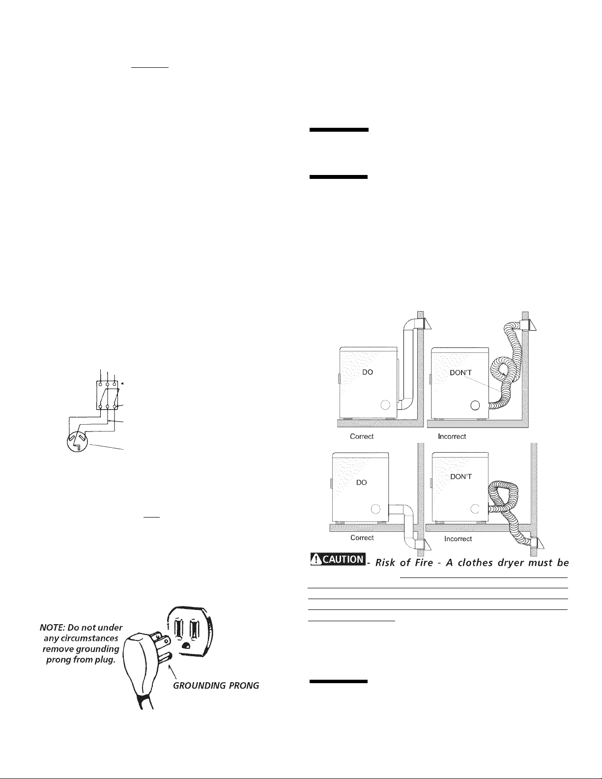
Use only 4 inch (10.2 cm) diameter (minimum) rigid or flexible
metal duct and approved vent hood which has a swing-out
damper(s) that open when the dryer is in operation. When the
dryer stops, the clampers automatically close to prevent drafts
and the entrance of insects and rodents. To avoid restricting the
outlet, maintain a minimum of 12 inches (30.5 cm) clearance
between the vent hood and the ground or any other obstruction.
WARNING
proper and safe operation of your dryer. Failure to follow
these instructions can create excessive drying times and
fire hazards.
ik WARNING
plastic venting materials. If your present system is made up
of plastic duct or metal foil duct, replace it with a rigid or flexible
metal duct. In Canada and the United States if metal (foil type)
duct is installed, it must be of a specific type identified by the
appliance manufacturer as suitable for use with clothes dryers
and in the United States must also comply with the Outline for
Clothes Dryer Transition Duct, UL standard 2158A. Elexible
venting materials are known to collapse, be easily crushed and
trap lint. These conditions will obstruct clothes dryer airflow and
increase the risk of fire. Ensure the present duct is free of
any lint prior to installing dryer duct.
The following are specific requirements for
Do not install a clothes dryer with flexible
Typical 3-wire installation
POWER SUPPLY
3 WIRE GROUNDED NEUTRAL
. 120-240 VOLT 60 CYCLE
MAIN FUSE BOX
30 AMP DELAYED ACTION
FUSES
. OR CIRCUIT BREAKER
NEUTRAL WIRE
OUTLET
RECEPTACLE
(COPPER)
SUBJECT TO LOCAL REGULATIONS MEMA 10-30R (COPPER)
GAS Dryer
CIRCUIT - Individual 15 amp. branch circuit fused with a 15 amp.
maximum time delay fuse or circuit breaker.
POWER SUPPLY - 3 wire, 120 volt single phase, 60 Hz,
Alternating Current.
POWER SUPPLY CORD - The dryer is equipped with a 120 volt
3-wire power cord.
exhausted outdoors Do not exhaust dryer into a chimney, a
wall, a ceiling, an attic, a crawl space or any concealed space
of a building. A clothes dryer produces combustible lint. If the
dryer is not exhausted outdoors, some fine lint will be expelled
into the laundry area. An accumulation of lint in any area of the
home can create a health and fire hazard.
The dryer must be
connected to an exhaust outdoors. Regularly inspect the
outdoor exhaust opening and remove any accumulation of lint
around the outdoor exhaust opening and in the surrounding
area.
A WARNING
Do not allow combustible materials (for
example: clothing, draperies/curtains, paper) to come in
contact with exhaust system. The dryer MUST NOT be
exhausted into a chimney, a wall, a ceiling, or any concealed
space of a building which can accumulate lint, resulting in a fire
hazard.
Page 4
ià WARN ING
I Exceeding the length of duct pipe or number
of elbows allowed in the “MAXIMUM LENGTH" charts can
cause an accunnulation of lint in the exhaust systenn. Plugging
the systenn could create a fire hazard, as well as increase drying
tinnes.
ià WARNING
Do not screen the exhaust ends of the vent
system, nor use any screws, rivets or other fastening means
that extend into the duct and catch lint to assemble the
exhaust system. Lint can beconne caught in the screen, on the
screws or rivets, clogging the duct work and creating a fire hazard
as well as increasing drying tinnes. Use an approved vent hood
to terminate the duct outdoors, and seal all joints with duct tape.
All male duct pipe fittings MUST be installed downstream with
the flow of air.
ik WARNING
Explosion hazard. Do not install the dryer
where gasoline or other flammables are kept or stored. If
the dryer is installed in a garage, it must be a minimum of 18
inches (45.7 cm) above the floor. Failure to do so can result in
death, explosion, fire or burns.
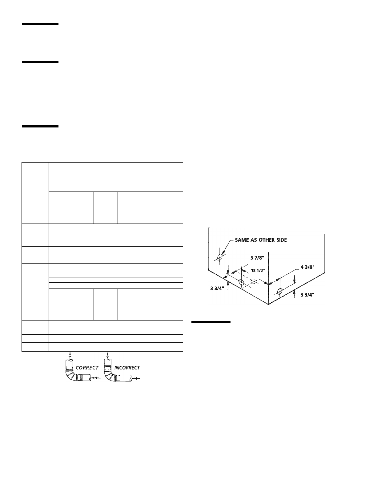
MAXIMUM LENGTH
of 4" (10.2 cm) Dia. Rigid Metai Duct
VENT HOOD TYPE
Number
of
90°
Turns
0 60 ft.(18.28 m) 48 ft. (14.63 m)
1 52 ft.(15.84 mi 40 ft. (12.19 mi
2 44 ft.(13.41 m) 32 ft. (9.75 m)
3 32 ft.(9.75 m) 24 ft. (7.31 mi
4 28 ft. (8. S3 m) 16 ft. (4.87 mi
Number
of
90°
Turns
(Preferred)
Louv ired
i
(10.2 cm)
MAXIMUM LENGTH
of 4" (10.2 cm) Dia. Fiexibie Metai Duct
VENT HOOD TYPE
(Preferred)
Louvt^red
5^k-
(6.35 cm)
than 0.75 inches of water column, the system is acceptable.
If the manometer reading is higher than 0.75 inches of water
column, the system is too restrictive and the installation is
unacceptable.
Although vertical orientation of the exhaust system is acceptable,
certain extenuating circumstances could affect the performance
of the dryer:
• Only the rigid metal duct work should be used.
• Venting vertical through a roof may expose the exhaust system
to down drafts causing an increase in vent restriction.
• Running the exhaust system through an uninsulated area may
cause condensation and faster accumulation of lint.
• Compression or crimping of the exhaust system will cause an
increase in vent restriction.
The exhaust system should be inspected and cleaned a minimum
of every 18 months with normal usage. The more the dryer is
used, the more often you should check the exhaust system and
vent hood for proper operation.
EXHAUST DIRECTION
All dryers shipped from the factory are set up for rear exhausting.
However, on electric dryers, exhausting can be to the right or left
side of the cabinet or the bottom of the dryer. On gas dryers,
exhausting can be to the right side of the cabinet or the bottom of
the dryer. Directional exhausting can be accomplished by installing
Exhaust Kit, P/N 131456800, available through your parts
distributor. Follow the instructions supplied with the kit.
EXHAUST DUCT LOCATING DIMENSIONS
i
(10.2 cm)
0 30 ft. (9.14 m) 18 ft. (5.49 m)
1 22 ft. (6.71 mi 14 ft. (4.27 mi
2 14 ft. (4.27 mi 10 ft. (3.05 mi
3 NOT RECOMMENDED
INSTALL MALE FITTINGS IN CORRECT DIRECTION
5^k-
(6.35 cm)
In installations where the exhaust system is not described in the
charts, the following method must be used to determine if the
exhaust system is acceptable:
1. Connect an inclined or digital manometer between the
dryer and the point the exhaust connects to the dryer.
Set the dryer timer and temperature to air fluff (cool down)
and start the dryer.
Read the measurement on the manometer.
The system back pressure MUST NOT be higher than 0.75
inches of water column. If the system back pressure is less
GAS SUPPLY REQUIREMENTS
A WARNING
plastic-coated. Stainless steel or plastic-coated brass MUST
be used.
1 Installation MUST conform with local codes, or in the absence
of local codes, with the National Fuel Gas Code, ANSI Z223.1
(latest edition).
The gas supply line should be of 1/2 inch (1.27 cm) pipe.
If codes allow, flexible metal tubing may be used to connect
your dryer to the gas supply line. The tubing MUST be
constructed of stainless steel or plastic-coated brass.
The gas supply line MUST have an individual shutoff valve.
A 1/8 inch (0.32 cm) N.RT plugged tapping, accessible for
test gauge connection, MUST be installed immediately
upstream of the gas supply connection to the dryer.
The dryer MUST be disconnected from the gas supply piping
system during any pressure testing of the gas supply piping
system at test pressures in excess of 1/2 psig (3.45 kPa).
The dryer MUST be isolated from the gas supply piping system
during any pressure testing of the gas supply piping system at
test pressures equal to or less than 1/2 psig (3.45 kPa).
Replace copper connecting pipe that is not
Page 5
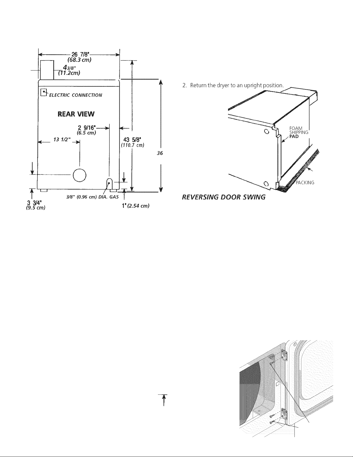
ROUGH-IN DIMENSIONS
UNPACKING
1. Using the four shipping carton corner posts (two on each
side), carefully lay the dryer on its left side and rennove foann
shipping base.
 CAUTION
I
To prevent dannage, do not use the control panel
or coin nneter housing as a nneans to pick up or nnove the dryer.
Your dryer is designed so the door swing nnay be reversed at any
tinne without additional parts. Conversion is accomplished by
transferring hinges to the opposite side of the cabinet.
To change the direction of the door opening:
DOOR OPEN 90'
47 1/2"
(120.7 cm)
SIDE VIEW
4 3/8"
Cl 1.1 cm)
OPTIONAL
VENT KNOCKOUT
27‘
(68.6 cm)
1. Open the dryer door. Remove the four hinge hole plugs from
the left side of the door opening. Place nearby for future
installation.
NOTE. You may need a plastic knife to help pull out the plugs.
Be careful not to scratch the paint.
2. Remove the four screws that secure the door hinges to the
dryer front panel (see below). NOTE: Remove one screw from
each of the two hinges first. Hold the door firmly before
removing the last two screws.
3. Rotate the door 180° and reinstall the door hinges to the dryer
front panel with the four screws.
4. Install the four
hinge hole plugs
in the open
screw holes on
the right side of
the door
opening.
y 3/4"
(9.5 cm)
(Figure 1)
REMOVE 4 SCREWS
(ONE EROM EACH
HINGE FIRST)
Page 6
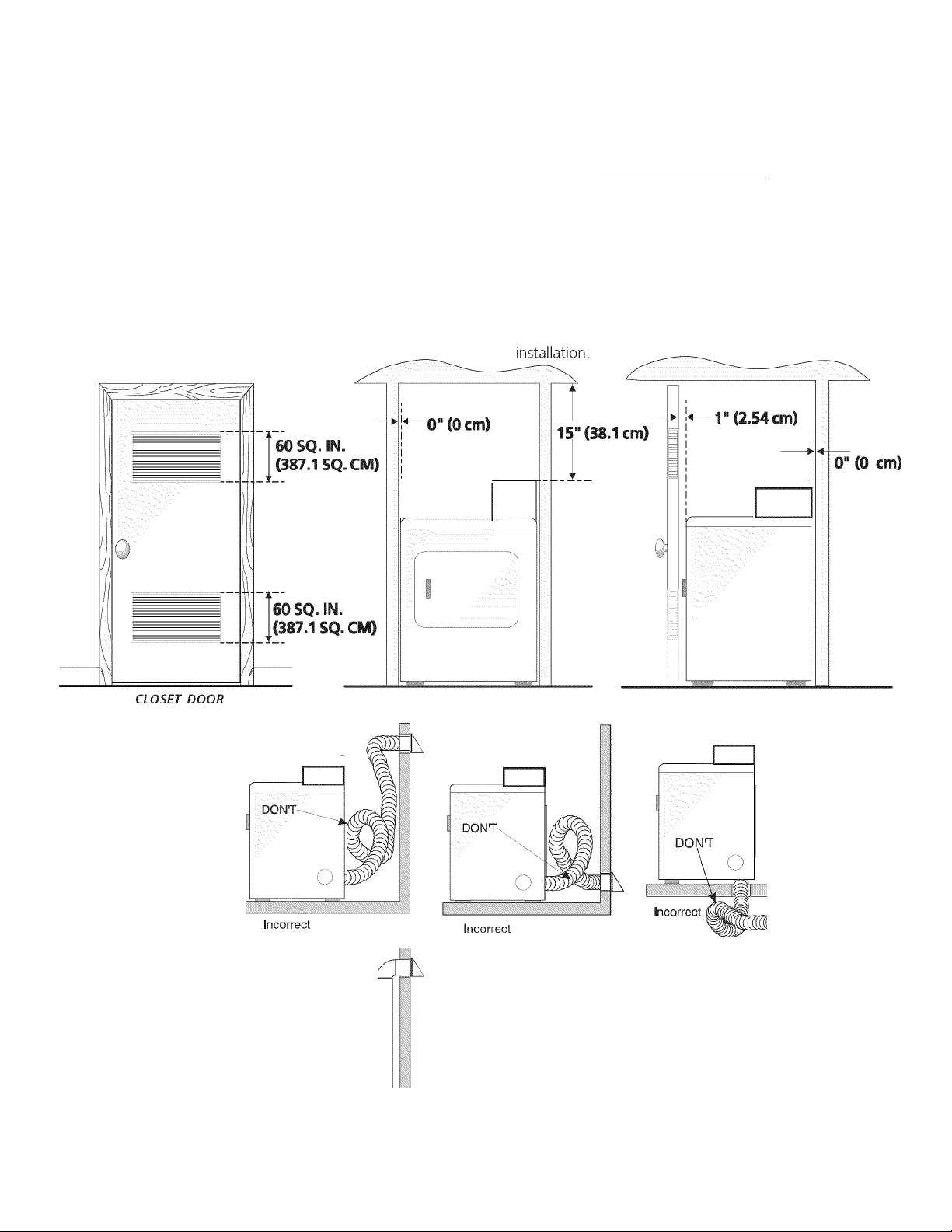
DO NOT INSTALL YOUR DRYER:
1. In an area exposed to dripping water or outside weather
conditions.
2.
In an area where it will conne in contact with curtains, drapes,
or anything that will obstruct the flow of combustion and
ventilation air.
3
On carpet. Floor MUST be solid with a maximum slope of 1
inch (2.54 cm).
INSTALLATION IN RECESS OR CLOSET
1. A dryer installed in a bedroom, bathroom, recess or closet,
MUST be exhausted outdoors.
2. No other fuel burning appliance shall be installed in the
same closet as the Gas dryer.
Your dryer needs the space around it for proper ventilation.
3.
DO NOT INSTALL YOUR DRYER IN A CLOSET WITH A
SOLID DOOR.
4. A minimum of 120 square inches (JlA.l square cm) of
opening, equally divided at the top and bottom of the door,
is required. Air openings are required to be unobstructed
when a door is installed. A louvered door with equivalent
air openings for the full length of the door is acceptable.
MINIMUM INSTALLATION CLEARANCES (Inches)
FRONT SIDES REAR TOP
Alcove 0 (0 cm) 0 (0 cm) 0 (0 cm) 15 (38.1 cm)
Closet 1 (2.54 cm) 0 (0 cm) 0 (0 cm) 15(38.1 cm)
Closet door ventilation required: 2 louvered openings each 60
square inches (387 square centimeters) — 3 inches (7.6 cm)
from bottom and top of door.
THIS DRYER MUST BE EXHAUSTED OUTDOORS.
5. The following illustrations show minimum clearance
dimensions for proper operation in a recess or closet
Rigid
Metal
Only
Correct Correct
6
Rigid
Metal
Only
Rigid
Metal
Only
Correct
Page 7

ELECTRICAL INSTALLATION
GROUNDING REQUIREMENTS
Before proceeding with electrical installation, install the
dryer's coin-nnetering systenn (when used) in accordance
with the separate instructions provided with the nneter.
ALL ELECTRIC Dryers
ik WARNING
proper and safe electrical installation of your dryer. Failure
to follow these instructions can create electrical shock and/
or a fire hazard.
WARNING
Electrical shock can result if the dryer is not properly grounded.
Follow the instructions in this nnanual for proper grounding.
WARNING
Sonne extension cords are not designed to withstand the announts
of electrical current this dryer utilizes and can nnelt, creating
electrical shock and/or fire hazard. Locate the dryer within reach
of the receptacle for the length power cord to be purchased,
allowing some slack in the cord. Refer to the pre-installation
requirements in this manual for the proper power cord to be
purchased.
WARNING
power cord. If the strain relief is not attached, the cord can be
pulled out of the dryer and can be cut by any movement of the
cord, resulting in electrical shock.
WARNING
a copper wired power cord and plug (or vice versa). A chemical
reaction occurs between copper and aluminum and can cause
electrical shorts. The proper wiring and receptacle is a copper
wired power cord with a copper wired receptacle.
The following are specific requirements for
This appliance MUST be properly grounded.
Do not use an extension cord with this drver.
A U.L. listed strain relief must be Installed onto
Do not use an aluminum wired receptacle with
ELECTRIC Drver
iàDANGER
grounding conductor can result in a risk of electrical shock. Check
with a licensed electrician if you are in doubt as to whether the
appliance is properly grounded.
For a grounded, cord-connected drver:
1. The dryer ML/ST'be grounded. In the event of a malfunction
or breakdown, grounding will reduce the risk of electrical
shock by a path of least resistance for electrical current.
2. If your dryer is equipped with a power supply cord having an
equipment-grounding conductor and a grounding plug, the
plug MUST be plugged into an appropriate, copper wired
receptacle that is properly installed and grounded in
accordance with all local codes and ordinances. If in doubt,
call a licensed electrician. Do not modify plug provided
with the appliance.
For a permanently connected drver:
1. The dryer MUST be connected to a grounded metal,
permanent wiring system; or an equipment grounding con
ductor must be run with the circuit conductors and connected
to the equipment-grounding terminal or lead on the appliance.
This dryer is equipped with a three-prong (grounding) plug for
your protection against shock hazard and should be plugged
directly into a properly grounded three-prong receptacle. Do not
cut or remove the grounding prong from this plug.
Improper connection of the equipment
ALL GAS Dryers
NOTE: Dryers operating on 208 volt power supply will have
longer drying times than operating on 240 volt power supply.
Page 8
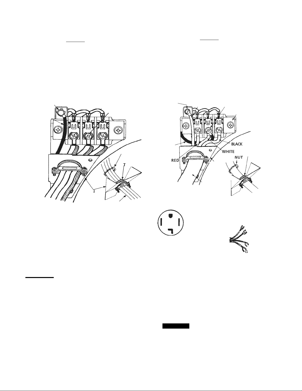
ELECTRICAL CONNECTIONS
FOR 3-WIRE SYSTEM
ELECTRICAL CONNECTIONS
FOR 4-WIRE SYSTEM
ELECTRIC Drver
Remove the screws securing the terminal block access cover
and the strain relief mounting bracket located on the back of
the dryer upper corner.
Install a U.L. listed strain relief into the power cord entry hole
of the mounting bracket. Finger tighten the nut only at this
time.
GREEN GROUND
SCREW
NEUTRAL
GROUND
WIRE
SILVER TERMINAL
NUT
TIGHTEN NUT
TO THESE
HREADS
ELECTRIC Drver
1. Remove the screws securing the terminal block access cover
and the strain relief mounting bracket located on the back of
the dryer upper corner.
2. Install a U.L. listed strain relief in the entry hole of the mounting
bracket. Finger tighten the nut only at this time.
3. Remove the ground wire from the green ground screw located
above the terminal block.
GREEN POWER CORD
GREEN
GROUND
SCREW
NEUTRAL
GROUND
WIRE
GROUND WIRE
'STRAIN
MOUNTING
BRACKET^
RELIEF
SILVER TERMINAL
TERMINAL
BLOCK
TIGHTEN NUT
TO THESE
THREADS
STRAir
RELIEF
MOUNTING
BRACKET POWER CORD
Thread a U.L. listed 30 amp. power cord, NEMA 10-30 Type
SRDT, through the strain relief.
Attach the power cord neutral (center wire) conductor to the
silver colored center terminal on the terminal block. Tighten
the screw securely.
Attach the remaining two power cord outer conductors to
the outer brass colored terminals on the terminal block. Tighten
both screws securely.
A WARNING
Do not make a sharp bend or crimp wiring/
conductor at connections.
Reattach the strain relief mounting bracket to the back of
the dryer with two screws. Tighten screws securely.
Tighten the screws securing the cord restraint firmly against
the power cord.
Tighten the strain relief nut securely so that the strain relief
does not turn.
Reinstall the terminal block cover.
POWER
CORD
4. Thread a U.L. listed 30 amp power cord, NEMA 14-30 type
ST or SRDT through the strain relief.
TYPICAL 4
CONDUCTOR
RECEPTACLE
TYPICAL 4
CONDUCTOR CORD
30 AMP NEMA 14-30 TYPE SRDT OR ST
BLACK 240V
WHITE NEUTRAL
RED 240V
REEN GROUND
5. Attach the green power cord ground wire to the cabinet with
the green ground screw.
6. Attach the white (neutral) power cord conductor from the
power cord and the neutral ground wire from the dryer harness
(removed from the ground screw In step 3) to the silver-colored
center terminal on the terminal block. Tighten the screw
securely.
Attach the red and black power cord conductors to the outer
7
brass colored terminals on the terminal block.
WARNING
Do not make a sharp bend or crimp wiring/
conductor at the connections.
8. Tighten the screws securing the cord restraint firmly against
the power cord.
9. Tighten the strain relief nut securely so the strain relief does
not turn.
10. Reinstall the terminal block access cover.
8
Page 9
INSTALLATION
1. GAS CONNECTION (Gas dryers only)
a. Remove the shipping cap from gas pipe at the rear of the
dryer.
NOTE: DO NOT connect the dryer to L.R gas service without
converting the gas valve. An L.R conversion kit must
be installed by a qualified gas technician.
b. Connect a 1/2 inch (1.27 cm) I.D. semi-rigid or approved
pipe from gas supply line to the 3/8 inch (0.96 cm) pipe
located on the back of the dryer. Use a 1/2 inch to 3/8
inch (1.27 cm to 0.96 cm) reducer for a connection. Apply
an approved thread sealer that is resistant to the corrosive
action of liquefied gases on all pipe connections.
Lint Blade Retaining Pin Location and Orientation
c. Open the shutoff valve in the gas supply line.
d. Test all connections by brushing on a soapy water solution.
NEVER TESTFOR GAS LEAKS WITH AN OPEN FLAME.
2. Connect the exhaust duct to outside exhaust system. Use
duct tape to seal all joints.
3. With the dryer in its final position, adjust one or more of the
legs until the dryer is resting solid on all four legs. RIace a
level on top of the dryer. THE DRYER MUST BE LEVEL AND
RESTING SOLID ON ALL FOUR LEGS.
4. Rlug the power cord into a grounded outlet. NOTE: Check
to ensure the power is off at circuit breaker/fuse box before
plugging the power cord into the outlet.
5. Turn on the power at the circuit breaker/fuse box.
 CAUTION Before operating the dryer, make sure the
dryer area is clear and free from combustible materials,
gasoline, and other flammable vapors. Also see that nothing
(such as boxes, clothing, etc.) obstructs the flow of combustion
and ventilation air.
6. Run the dryer through a cycle check for proper operation.
NOTE: On gas dryers, before the burner will light, it is
necessary for the gas line to be bled of air. If the burner does
not light within 45 seconds the first time the dryer is turned
on, the safety switch will shut the burner off. If this happens,
turn the timer to "OEE" and wait 5 minutes before making
another attempt to light.
Install the pins after the lint blade is installed.
METER CASE INSRUCTIONS
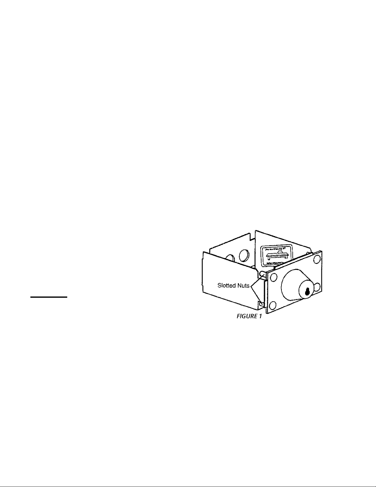
COIN BOXADJUSTMENT
The tight fit of the money box is set at the factory. Customer
may loosen fit as desired by loosening the slotted nuts. See
EIG.1.
Keep A record of all coin-box key numbers. A lost key can
only be replaced by ordering the key numbers from the place
were the unit was purchased. The key number is located both
on the key and behind the end panel of the coin box. If the key
number is not available, the lock must be drilled out to remove
the coin box.
7. RIace these instructions in a location near the dryer for future
reference.
NOTE: A wiring diagram is located inside the dryer.
Page 10
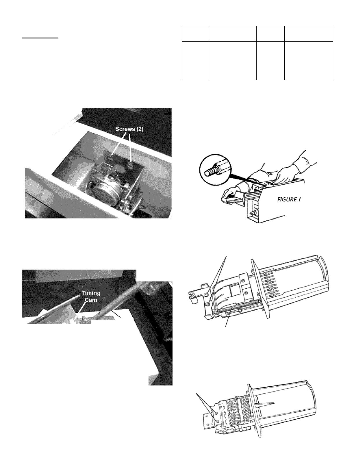
REPLACING NYLON TIMING CAMS ON ACCUMULATOR
MECHANISM
WARNING
I
Electrical Shock Hazard
• Disconnect both power supply cords from the electric
power supply before making these changes.
• Change timing cams before completing electrical
connection. Failure to do so could result in electrical
shock or personal injury.
A. Remove meter-case service door:
1. Loosen two screws securing timer bracket to meter case
and lift timer assembly out. See FIG. 2
FIGURE 2
Timing Cam Pin Chart
NUMBER
OF PINS
1
2
3
4
5
6
TIME PER
COIN INSERTED OF PINS
180 m in ut es
90
60
45
36
30
NUMBER TIME PER
COIN INSERTED
1 25. 7
8 22. 5
9 20
10 18
11 16 .3
12 15
INSTRUCTIONS FOR CHANGING VEND PRICE
TOOLS NEEDED
• Medium sized slotted screwdriver
• Small slotted Phillips screwdriver
Place all screws and other items removed from coin slide assembly
on a cloth so they will not get lost.
STEP1
Remove slide mechanism from meter case
(see FUGURE 1).
Remove nylon timing cam:
1. Rotate cam by hand until "V" notch lines up underneath
the ratchet tooth. See FIG. 3.
2. Insert narrow screwdriver under nylon cam close to the
timer shaft. Lift cam gently off shaft. Make sure that
pressure is directed upward and the "V" notch clears
the ratchet tooth.
Lift
iently
with
" ....
Lug
FIGURES
C.
Replace new timing cam:
1. Be sure drive lug is in place. Place cam (hub down) over
timer shaft, lining up flat on shaft with flat of drive lug
hole.
2. Rotate cam until "V" notch lines up with ratchet tooth.
3. Press down to seat cam on timer shaft, make sure that
"V" notch freely clears ratchet tooth.
STEP 2
Remove the coin slide extension from coin slide by removing
two mounting screws and spacers
(see FIGURE 2).
(2) Mounting Screws
and Spacers
FIGURE 2
Slide Return Spring
STEPS
Remove coin slide from coin chute:
• Unhook and remove the coin slide return spring
(see EIGURE 2).
• Turn coin slide mechanism upside down.
• Remove coin slide stop by taking out two screws to the chute
bottom (see EIGURE 3).
(2) Slide Stop Screws
FIGURES
10
Page 11
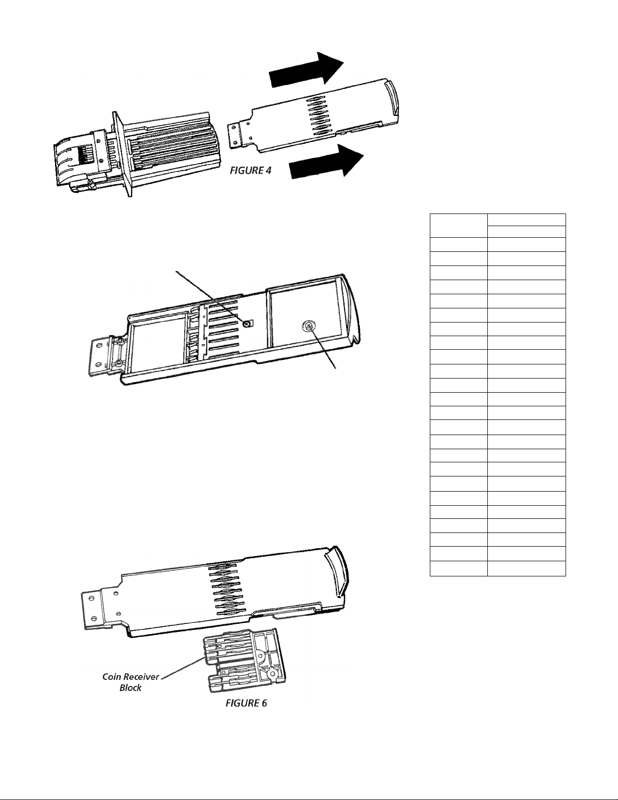
Pull coin slide out of coin chute (see FIGURE 4).
STEP 4
Turn coin slide upside down and rennove screw that holds coin receiver block
(see FIGURE 5).
(1) Receiver
Block Screw
FIGURES
STEPS
Remove coin receiver block from coin slide
(see FIGURE 6):
• Turn coin slide right side up. Keep coin receiver block in place with your fingers.
• Carefully lift coin slide from coin receiver block. If necessary, shake coin slide gently
to loosen block.
Spare Parts
Compartment
and Screw
STEPS
Set new vend price by adding or
removing the appropriate block-out
keys and/or dime inserts according
to th Table of Vend Prices
(see FIGURE 7).
NOTE: Black colored slots are
closed off by block-out key.
FIGURE?
TABLE OF VEND PRICE
VEND COIN SLOTS
12345678
0
$.10
$.20
$.25
$.35
$.45
$.50
$.60
$.70
$.75
$.85
$.95
$1.00
$1.10
$1.20
$1.25
$1.35
$1.45
$1.50
$1.60
$1.70
$1.75
$1.85
$2.00
III mil
□ 1111111
□
D
1 1 1 1 1 1
IID 1II II
□ 1 D 1 1 1 11
□
□DIMM
II D D II 11
□ 1 D D11 1 1
□ □ D D 11 1 1
1 1 D D D 1 1 1
□ 1 D D D 1 1 1
□□DDDIII
11 D D D D 1 1
□IDDDDII
□□DDDDIi
1 D D D D D 1 1
□ ■ D D D D D ■
□□DDDDDI
■ D D D D D D ■
□DDDDDDI
□□DDDDDD
IDDDDDDD
□DDDDDDD
D D D D D D D D
11
Page 12
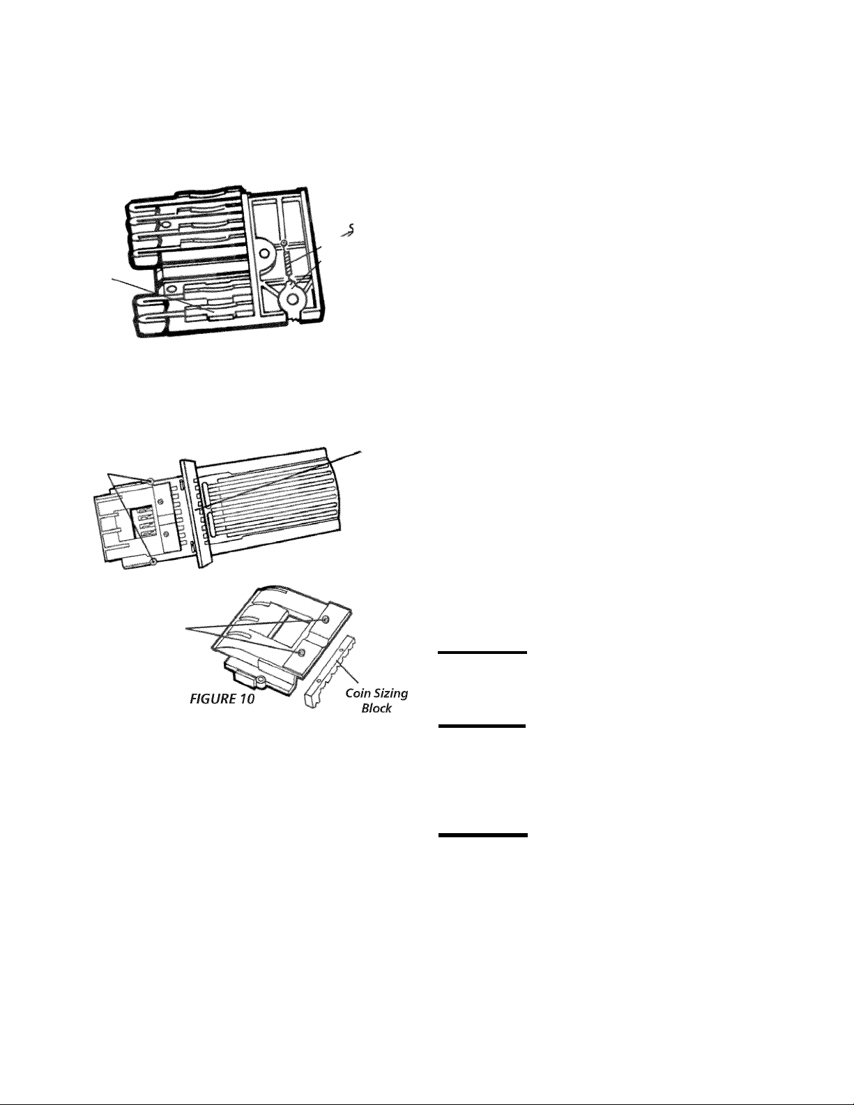
To remove block-out keys, pull straight up.
NOTE: Be sure block-out keys and /or dime inserts are seated
properly and ratchet dog is in place with irs spring connected
(see FIGURE 8).
Be sure the proper coin sizing block is in place.
STEP?
Replace coin receiver block into slide:
• Flold coin receiver right side up in the palm of one hand.
• Lower coin slide until coin receiver block fits into the coin
slide cavity. CAUTION: Do not dislodge ratchet dog and
spring.
Ratchet
Dog and
Block-Out
Keys
FIGURES
Change coin sizing block:
• Remove two screws that hold upper coin chute cover.
Remove cover (see FIGURE 9).
(2) Upper Coin
Chute Cover
Screws
(2) Coin Sizing
Block Screws
FIGURED
pring
Anti-Cheat
Gate
• Flold coin receiver block in place with your fingers and turn
slide upside down.
• Insert and tighten screw.
STEPS
Install slide into coin chute. Slide can only be pushed in if the
anti-cheat gate in flange is pushed to the left, (see FIGURE 9).
STEP 9
Replace coin slide stop with two screws. Replace coin slide
return spring. Replace coin slide extension with two screws (be
sure spacers are in place).
STEP 10
Replace coin slide mechanism in meter case. Replace and tighten
coin slide mounting bolt.
NOTE: It may be easier to insert coin slide mounting bolt if you
remove the timer from the mounting screws temporarily.
REPLACEMENT PARTS
If replacement parts are needed for your dryer, contact the source
where you purchased your dryer, or call Sears Parts and Service
Toll Eree Number 1-800-4-MY-HOME (1 -800-469-4663). Eor coin
box parts, call 1 -800-221-0982, Greenwald Industries.
Remove two screws that hold coin sizing block to upper coin
chute cover cover (see EIGURE 10).
Put new coin sizing block in place. Reinsert and tighten
mounting screws.
Replace coin chute cover. Reinsert and tighten screws.
À CAUTION
Label all wires prior to disconnection when
servicing controls. Wiring errors can cause improper and
dangerous operation. Verify proper operation after servicing.
WARNING
Destroy the carton and plastic bags after the
dryer is unpacked. Children might use them for play. Cartons
covered with rugs, bedspreads, or plastic sheets can become
airtight chambers causing suffocation. Place all materials in a
garbage container or make materials inaccessible to children.
WARNING
The instructions in this manual and all other
literature included with this dryer are not meant to cover every
possible condition and situation that may occur. Good safe
practice and caution MUST be applied when installing, operating
and maintaining any appliance.
12
Page 13
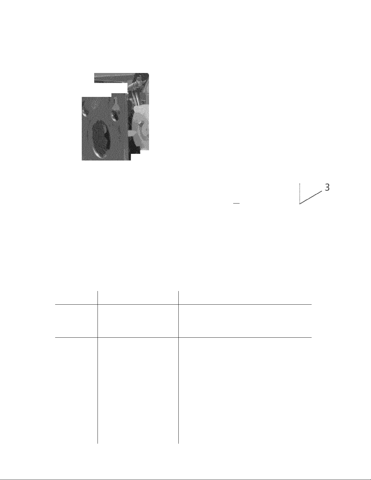
Meter Case Parts List
à _ I ■
Timer Assembly
Mode! 50-1232-9
Hfl^H
0^B
■
M
, >/3s«tÂ
■
■
■ra
iM
Timer Assembly
Model 50-1223-10
ITEM PART NUMBER DESCRIPTION
1
2
3
Additional
cams that
are available.
Cams pull
off and push
on for
replacement.
50-61-13-2 Timing motor, 115VAC, 1/180RPM
51-161-4 Timing cam, 4-PIN (45 Minutes)*
00-6164 Switch
51-161-1 Timing cam,1-PIN (180 Minutes)
51-161-2 Timing cam,2-PIN (90 Minutes)
51-161-3 Timing cam,3-PIN (60 Minutes)
51-161-5 Timing cam,5-PIN (36 Minutes)
51-161-6 Timing cam,6-PIN (30 Minutes)
51-161-7 Timing cam,7-PIN (25.7 Minutes)
51-161-8 Timing cam,8-PIN (22.5 Minutes)
51-161-9 Timing cam,9-PIN (20 Minutes)
51-161-10 Timing cam,10-PIN (18 Minutes)
51-161-11 Timing cam,11-PIN (16.3 Minutes)
51-161-12 Timing cam,12-PIN (15 Minutes)
13
Page 14
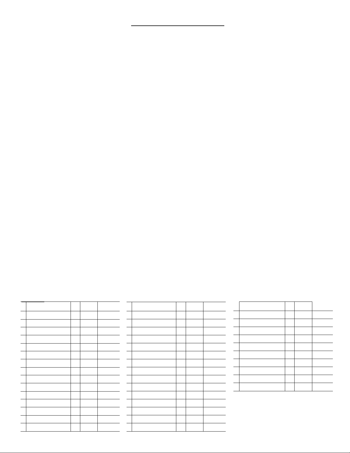
V8 Coin Chute Parts List
• S’r’rrsfY yi.NO
. ^ au-’-N i;"'- »l^VN ‘-■’.'iS'' L --M.L'Cîr:
’X .
■•aü:
ftv:
( '
0{j\
‘W '>
.'IPS'!
:17;
;i’4’;
;'?3.
'.ri:
''¡£
'-si
iij'»
i!- \
:'2i':
V8 Parts List
DESCRIPTION REQ. 20-3020 20-3000
1 SCREW (METRIC ) 2 00-9724 00-7924
2 S CREW (METRIC) 2 00-7938 00-7938
3 TOP H OUSING 1 20-3019 20-3002
4 SH IM 2 20-2042
5 COIN SIZING BLOCK 1 20-3006 20-3006
6 G ATE COVER 1 20-2043 20-2006
7 G ATE 1 20-2035 20-2000
8 SLIDE STOP DOG 8 20-2011 20-2011
9 DOG SHAFT 1 20-4004 20-4000
10 DECAL,CASTING 1 00-9905 00-9905
11 BOD Y C ASTING 1 20-3020 20-3000
12 COIN SLIDE 1 20-3021
13 DECAL, SLIDE 1 00-9104 00-9104
14 CHU TE LOCATING SCREW 4 00-7483 61-55
15 SLIDE RETURN SPRING 1 00-8148 00-8148
CHU rt'
MODtl
iü-EN'afiCATlON
NUWiBbü ON
BOlTOftI OF
cH u n
DESCRIPTION REQ. 20-3020 20-3000
16 SPRING 1 20-2040 20-2001
17 SPRING PROTECTOR 1 20-2038 20-2007
18 RAOK 1 20-2023 20-2005
19 SCREW (M ETRIC) 2 00-7931 00-7931
20 100 INSER T varies 20-3023 20-5001
21 S CREW (METRIC) 2 00-7923 00-7929
22 S LIDE STOP 20-2039 20-2004
23 R ATOHE TDOG SPR ING 00-8123 00-8123
24 B LOCKO UT KEY varies 20-5002 20-2010
25 SLIDE RATOHETDOG 20-2041 20-2008
26 STORAGE COMP . OOVER 20-2037 20-2003
27 SCREW (M ETRIO) 2 00-7935
28 BUFFE R 1 20-2034
29 RATCHET DO G POST 20-4005
30 C OIN RE TAINER optional Opt. 00-8168
14
F1Ü. 1 FU:i_ 2
DESCRIPTION REQ. 20-3020 20-3000
31 COIN SIZING BLOCK varies 20-3007 20-3007
32 PRES SURE SPRING ASMY Opt. 20-1012 20-1012
33 MA GNET Opt. 00-9256 00-9256
34 SHIELD Opt. 20-2045 20-2045
35 COIN RECEIVER BLOOK 1 20-2003
37 LOCK WASHER 1 00-7934
38 SCREW (M ETRIC) 00-7933
39 SCREW (M ETRIC) 00-7932
40 SCREW 00-7541 00-7541
41 T OP HOUSING ASM Y 20-1103-1 20-1104-1
Page 15

NEW VEND PRICE
To change vend price, detach and mail the lower portion to:
Customer Service Department
Greenwald Industries Inc.
212 Middlesex Ave.
Chester, CT 06412
The coin chute has been pre-set at the factory.
When increasing in $.25 pricing
Follow product information instructions; no extra parts required.
When decreasing in $.25 pricing - or - changing to
$.10 pricing.
(Coin sizing block required; see "Changing Vend Price"
section.)
SEARS COMMERCIAL DRYER WARRANTY
Order required parts using this tear-off. Block-out keys will be
shipped to you at no charge. Follow product information
instructions.
Quantity__________________________________________________________________
Existing Vend Price
Name
Company_
Address
___
City
_______
State/Zip_
Daytime phone_
Purchase date
_______________________________________________________
LIMITED 2-YEAR WARRANTY ON MECHANICAL AND ELECTRICAL PARTS
For two years from the date of purchase, when the dryer is installed and operated in accordance with the
instructions in the Installation Instructions/Use & Care Guide, Sears will furnish replacement parts for all
defective mechanical or electrical parts including coin box and chute assemblies. You will be charged
for labor.
WARRANTY SERVICE IS AVAILABLE BY CONTACTING THE NEAREST SEARS SERVICE
CENTER INTHE UNITED STATES.
This warranty applies only while this product is in use in the United States. This warranty gives you
specific legal rights, and you may also have other rights which vary from state to state.
Sears, Roebuck and Co., Dept. 817WA, Hoffman Estates, IL 60179
NOTE: IF the dryer is vented with a plastic or metal foil flexible duct and not a rigid or flexible metal duct,
this warranty is void. Pages 3-5 of this Installation Instruction/Use & Care Guide describe the complete
exhaust requirements for this washer
Notes
15
Page 16

Get it fixed, at your home or ours!
Your Home
For expert troubleshooting and home solutions advice:
www.managemyhome.com
For repair - in your home - of all major brand appliances,
lawn and garden equipment, or heating and cooling systems,
no matter who made it, no matter who sold it!
For the replacement parts, accessories and
owner’s manuals that you need to do-it-yourself.
For Sears professional installation of home appliances
and items like garage door openers and water heaters.
1-800-4
Call anytime, day or night(U.S.A. and Canada)
-MY-HOME® (i-
www.sears.com www.sears.ca
8
oo-
469-4663
)
Our Home
For repair of carry-in items like vacuums, lawn equipment,
and electronics, call anytime for the location of your nearest
Sears Parts & Repair Service Center
1-800-488-1222 (U S A ) 1-800-469-4663 (Canada)
www.sears.com www.sears.ca
To purchase a protection agreement on a product serviced by Sears:
1 -800-827-6655 (USA) 1 -800-361 -6665 (Canada)
Para pedir servicio de reparación
a domicilio, y para ordenar piezas:
1-888-SU-HOGAR®
(1-888-784-6427)
Au Canada pour service en français:
1-800-LE-FOYER“''
(1-800-533-6937)
www.sears.ca
® Registered Trademark / ™ Trademark / ™ Service Mark of Sears Brands, LLC
® Marca Registrada / ™ Marca de Fábrica / ™ Marca de Servicio de Sears Brands, LLC
Marque de commerce / Marque déposée de Sears Brands, LLC
© Sears Brands, LLC
 Loading...