

Page 1
OWNER’S
MANUAL
MODEL NO.
UltraFilter 150
625.385700
UltraFilter 350
625.385720
Caution:
Read and Follow
All Safety Rules and
Operating Instructions
Before First Use of
This Product.
If you have questions when
installing, operating or
maintaining your reverse
osmosis system, call this
toll-free number...
1-800-426-9345
(M - F, 7 am - 8 pm, CST)
For repair or replacement
parts, call this toll-free num
ber. ..
1-800-366-7278
See back cover for other
Sears service numbers.
WWW. Ken more Wate r.com
SAVE THIS MANUAL
Reverse Osmosis Drinking Water System
♦ Warranty
♦ Flow To Install
♦ How It Works
♦ Care Of
♦ Repair Parts
System tested and certified by NSF International
to NSF/ANSI Standard 58 for the reduction of the
claims specified on the performance data sheet.
Sears, Roebuck and Co., Hoffman Estates, IL 60179 U. S. A.
PRINTED IN U.S.A.
Part No. 7266568 (Rev. H 8/4/05)
Page 2

WARRANTY -
FULL WARRANTY ON REVERSE OSMOSIS DRINKING WATER SYSTEM
(except filter cartridges and R. O. membrane)
For one year from the date of purchase, when the Reverse Osmosis Drinking Water System is installed
and maintained in accordance with our instructions, Sears will repair, free of charge, defects in material
and workmanship, except filter cartridges and the R. O. membrane.
TO OBTAIN WARRANTY SERVICE, SIMPLY CONTACT THE NEAREST SEARS SERVICE CENTER
THROUGHOUT THE UNITED STATES. This warranty applies only while this product is in use in the
United States.
This warranty gives you specific legal rights, and you may have other rights which vary from state to state.
Sears, Roebuck and Co., D/817 WA, Hoffman Estates, IL 60179
I__________________________________________________________ I
SEARS INSTALLATION POLICY
All installation labor arranged by Sears shall be per
formed in a neat, workmanlike manner in accor
dance with generally accepted trade practices. Fur
ther, all installations shall comply with all local laws,
codes, regulations, and ordinances. Customer shall
also be protected during installation by insurance re
lating to Property Damage, Workman's Compensa
tion and Public Liability.
In addition to any warranty extended to you on the
Sears merchandise involved, which warranty be
comes effective the date the merchandise is installed,
should the workmanship of any Sears arranged
installation prove faulty within one year. Sears will,
upon notice from you, cause such faults to be cor
rected at no additional cost to you.
SEARS INSTALLATION WARRANTY
- SAFETY GUIDES -
Read all steps and guides carefully before instal
ling and using your reverse osmosis system. Follow
all steps exactly to correctly install. Reading this
manual will also help you to get all the benefits from
the reverse osmosis system.
^ Do not attempt to use this product to make safe
drinking water from non-po table water sources. Do
not use the system on microbiologically unsafe wa
ter, or water of unknown quality without adequate
disinfection before or after the system. This system
is certified for cyst reduction and may be used on
disinfected water that may contain filterable cysts.
^ Check with your local public works department
for plumbing and sanitation codes. You must fol
low their guides as you install the system. Follow
your local codes if they differ with guides in this
manual. Massachusetts plumbing code 248 CMR
shall be adhered to. Please consult your licensed
plumber.
This system shall only be used for arsenic reduc
tion on chlorinated water supplies containing de
tectable residual free chlorine at the system inlet.
Water systems using an inline chlorinator should
provide a one minute chlorine contact time before
the RO system.
Problems, Questions? Call 1
800-426-9345 Ken more Water Line
^ This system is acceptable for treatment of influ
ent concentrations of no more than 27 mg/L nitrate
and 3 mg/L nitrite in combination measured as N
and is certified for nitrate/nitrite reduction only for
water supplies with a pressure of 280 kPa (40 psig)
or greater. This system is supplied with a nitrate/nitrite test kit. Product water should be monitoredperiodically according to the instructions provided
with the test kit.
The reverse osmosis system works on water pres
sures of 40 psi (minimum) to 100 psi (maximum). If
your house water pressure is over the maximum,
install a pressure reducing valve in the water supply
pipe to the reverse osmosis system.
"Y Do not install the reverse osmosis system out
side, or in extreme hot or cold temperatures. Temper
ature of the water supply to the reverse osmosis sys
tem must be between 40 °F and 100°F. Do not install
on hot water.
Read the other limits (pH, hardness, etc.) in the
specifications and be sure your water supply con
forms. Also see "Water Supply" on page 4.
^ The reverse osmosis membrane contains a pre
servative for storage and shipment. Be sure to purge
as instructed on page 11 before using product water.
2
Page 3
- TABLE OF CONTENTS —
Where To install the RO System
Tools and Materials Needed
6 Steps to Install ..................................................... 4
Install Cold Water Supply Fitting
Install Drain Adapter
Install Faucet
Install RO Assembly
..........................................................
.............................................
.............................................
............................
..................................
.........................
4
4
5
6
6
9
WHAT YOUR REVERSE OSMOSIS SYSTEM WILL DO -
Your Reverse Osmosis (RO) Drinking Water System
is a water treatment unit. It uses household water
pressure to reverse a natural physical process called
osmosis. Water, under pressure, is forced through a
semi-permeable membrane where minerals and im
purities are filtered out. Clean drinking water goes to
the faucet or storage, while minerals and impurities
are sent to the drain with RO waste water. The miner
als and impurities are measured in water as total dis
solved solids (TDS).
The system includes replaceable pre and postfilter
sediment-carbon cartridges. The prefilter removes
sand, silt, dirt, rust particles, other sediments, and
chlorine from the water supply before it can enter the
Install Storage Tank, Make Tubing
Connections .......................................................... 10
Sanitizing, Pressure Test, Purging
Flow the RO System Works
Care of Your RO System
Dimensions, Specifications ..................................... 18
Remote Installation Locations
Repair Parts ............................................................. 20
RO membrane. The postfilter removes any tastes
and/or odors that may remain in the water, after
passing through the RO membrane, and just before
going to the RO faucet. To prevent water waste, an
automatic shutoff valve closes when the RO faucet is
closed and the storage tank is full.
Your reverse osmosis system gives you a continuous
supply of sparkling clear, delicious water for drink
ing, cooking and other uses. Foods will look and
taste better too. Fiaving high quality RO product wa
ter at your fingertips eliminates the need to buy
bottled water. The storage tank holds over 2 gallons
of RO product water for your needs.
...................................
........................................
.......................
................................
11
12
13
19
BEFORE YOU BEGIN TO INSTALL THE RO SYSTEM
FOR OPTIMUM PERFORMANCE YOUR KENMORE REVERSE OSMOSIS SYSTEM SHOULD BE
INSTALLED ON
CAUTION: A refrigerator icemaker may not operate
properly when connected to a reverse osmosis sys
tem that has been installed on a water system that op
erates outside of the specified pressures listed on
page 18.
Check Your Water Supply: The cold water supply to
the RO system must be within certain quality limits.
See the specification table on page 18. If supply water
is not within limits, the RO system can not make
product water as it should and reduced RO mem
brane life will result.
Trained sales people at Sears can perform a free water
analysis. This basic test can help determine if any
additional water treatment is required before the RO
system.
CAUTION: Chlorine in the water will destroy the
RO membrane. Most cities add chlorine to the water
supply to kill bacteria. The prefilter removes chlorine
up to the limits shown in the specifications before it
enters the RO membrane. It is important to replace
SOFTENED WATER.
the prefilter cartridge at least every 6 months. See
the RO care guide on page 15.
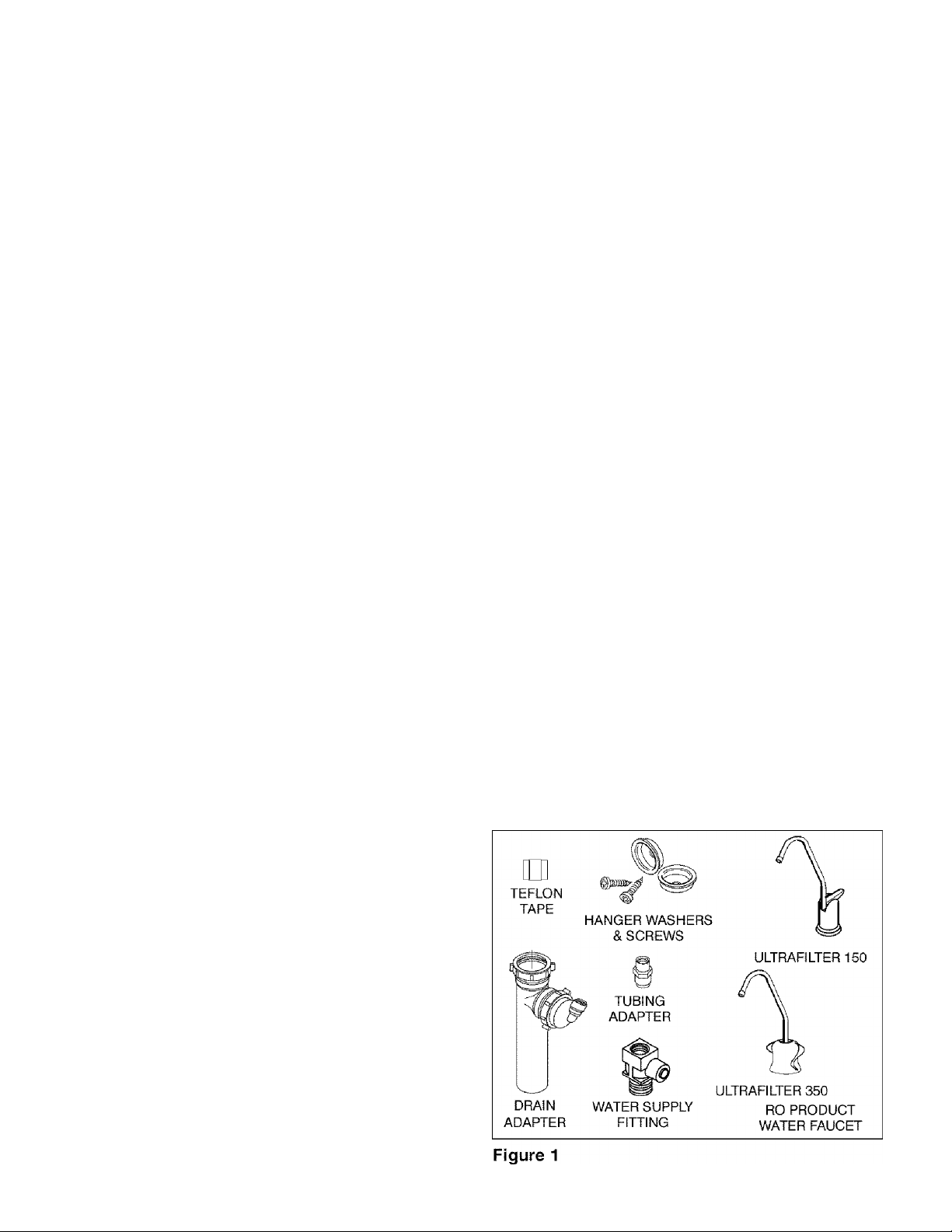
Check Parts Included: Unpack the carton and re
move the RO system. In addition to the assembled
RO and the storage tank, the system includes the
parts illustrated below, a separate length of tubing,
and this manual.
Problems, Questions? Call 1-800-426-9345 Kenmore Water Line
Page 4
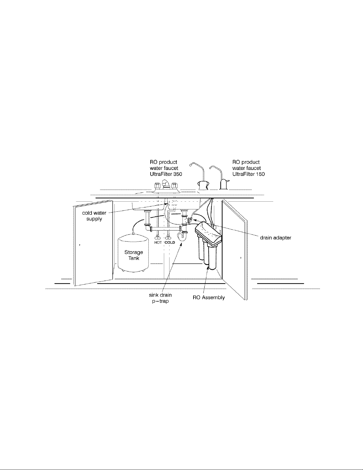
_ i"Q install the ro system “
The RO assembly and storage tank is designed for
installation under the sink, usually in the kitchen or
bathroom. The RO assembly mounts on a wall sur
face, or can lay on the cabinet floor next to the storage
tank. Hanger washers and wood screws are included
for cabinet wall mounting. The RO product water
faucet installs on the sink, or on the countertop next
to the sink (page 6).
Note: Tubing lengths allow for the removal of the as
sembly from the hanger washers for servicing. If tub
ing lengths are shortened for neater appearance, it
may be necessary to keep the assembly on the hanger
washers for service.
You can also locate the RO assembly and storage tank
in any remote location from the faucet, observing
safety guides on page 2. You do need a nearby water
source and drain point (see page 19).
Water Supply: To provide supply water to the RO
system inlet use the included feed supply fitting or
install pipe fittings for tubing connection, as typical
ly shown on page 5.
Drain Point: A suitable drain point is needed for re
ject water from the RO membrane. A floor drain,
laundry tub, standpipe, sump, etc., is preferred, as
shown in the remote locations drawing, page 19. A
sink p-trap drain adaptor is included to install where
codes permit, as an optional drain point (page 6).
Figure 2
- TOOLS AND MATERIALS NEEDED
^ adjustable wrench, standard pliers, and larger ^ electric drill and bits, if hole is needed for the RO
adjustable jaw pliers or pipe wrench to fit sink drain faucet, page 6.
^ slotted and Phillips head screwdrivers
► plumbers putty
- 6 STEPS TO INSTALL -
STEP 1: - Install Cold Water Supply fittings
STEP 2: - Install Drain Adapter
STEP 3: - Install Faucet
Problems, Questions? Call 1-800-426-9345 Kenmore Water Line
STEP 4: - Install RO Assembly
STEP 5: - Install Storage Tank, Make Remaining Tub
ing Connections
STEP 6: - Sanitizing, Pressure Testing, Purging
Page 5
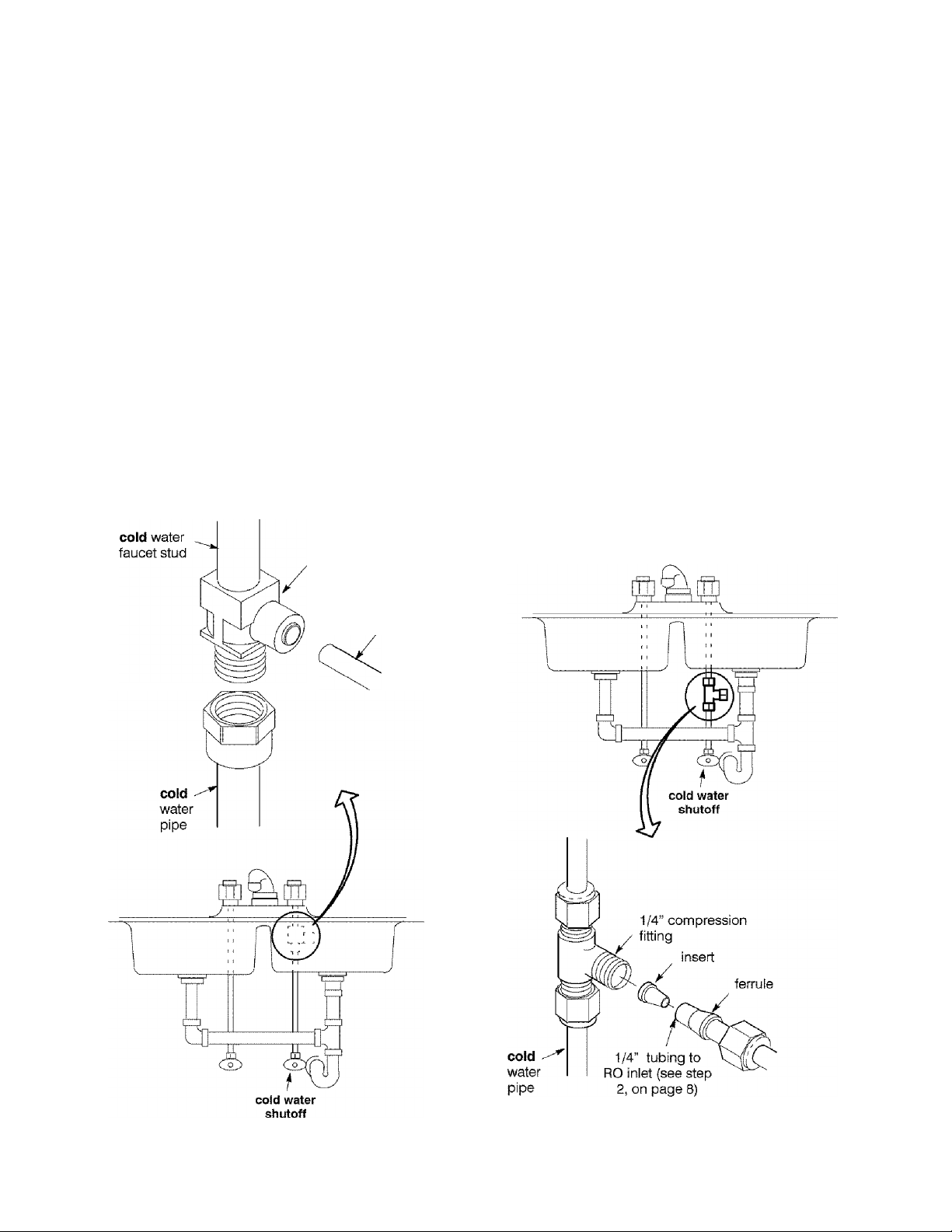
- STEP 1: INSTALL COLD WATER SUPPLY FITTING -
Check and comply with local plumbing codes as you plan, then install a cold feed (supply) water fitting. The
fitting must provide a leak-tight connection to the RO 1/4" tubing (see Figure 10, page 10). A typical connec
tion using the included water supply fitting is shown in Figure 3A below. An optional connection, using stan
dard plumbing fittings (not included), is shown in Figure 3B.
Note: Codes in the state of Massachusetts require installation by a licensed plumber, and do not permit the use of a saddle
valve. For installation, use plumbing code 248-CMR of the Commonwealth of Massachusetts.
A. WATER SUPPLY FITTING B. OPTIONAL PIPE FITTINGS (compression type
1. Close the house main water shutoff valve and open shown)
faucets to drain water from the sink cold water pipe. Note: Be sure to turn off the water supply and open
„ r> , ,1 , , ,1 u , r ,, a low faucet to drain the pipe.
2. Remove nut that connects the cold water faucet to ^ ^
cold water plumbing Complying with plumbing codes, install a fitting on
_ , „ , , the kitchen cold water pipe to adapt 1 /4" OD tubing.
3. Use pipe lomt compound or Teflon tape on cold water a . ■ i i ■ r- -»n Vr
. ^ , 1 ^ , r , A. typical connection is shown in Figure 3d. it
faucet stud threads and on the male threads of the water , i j j r-,, • j i , ■ ■ ■ ,
, , , , , - threaded fittings are used, be sure to use pipe loint
supply fittme that connect to the cold water pipe. i Id ^ - j ,i j
rf ^ f f compound or Teflon tape on outside threads.
4. Thread water supply fitting onto pipe and reconnect
nut to bottom of fitting.
A. WATER SUPPLY CONNECTION
(using Included water supply fitting)
water supply fitting
1/4” green tubing to
RO inlet (see step 2, on
page 8)
B. WATER SUPPLY TYPICAL CONNECTION
(using compression fitting)
- parts not included -
Figure 3
Problems, Questions? Call 1-800-426-9345 Kenmore Water Line
Page 6
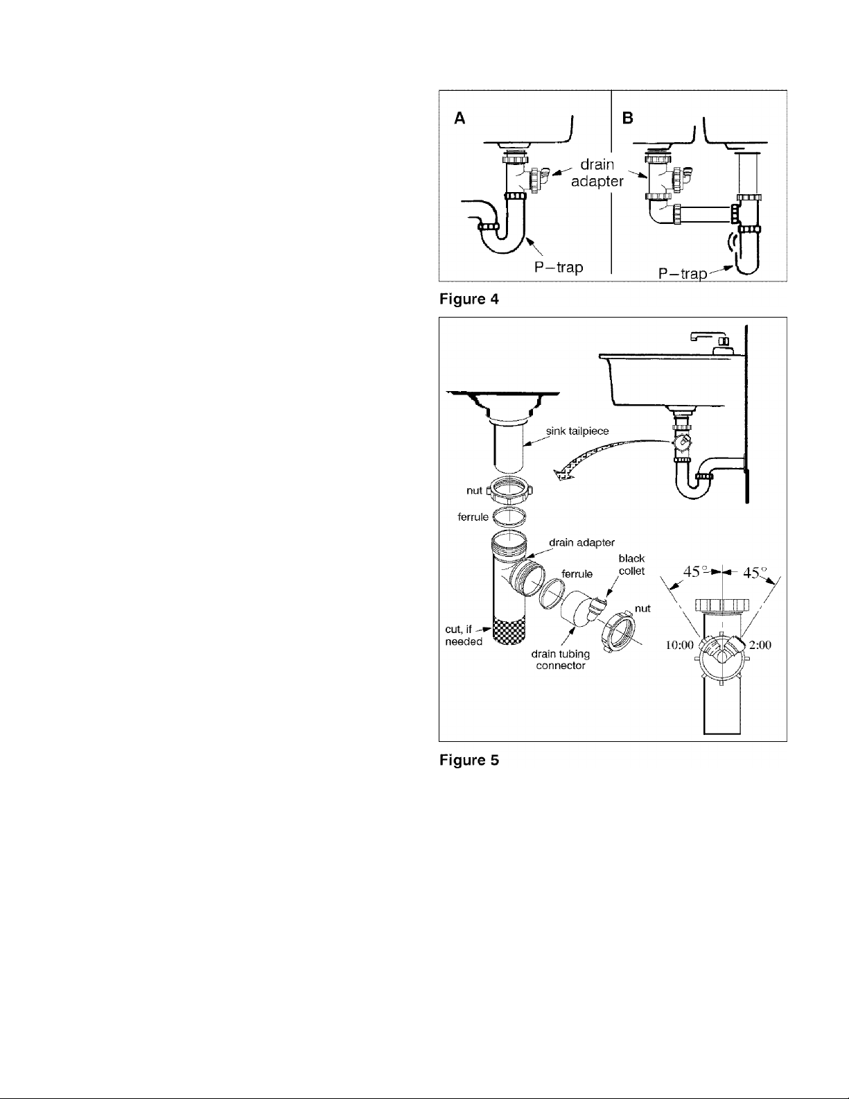
- STEP 2: INSTALL DRAIN ADAPTER -
■ Note: Running the drain tubing directly to a floor
drain, sump, standpipe, laundry tub, etc., as shown
on page 19, is preferred. However, if that is not pos
sible or practical, the included drain adapter installs
in the sink drain pipe, always above or ahead of the
p-trap, Figure 4. Be sure to comply with your local
plumbing codes. Other drain pipe fittings, in addi
tion to the adapter, may be needed.
■ The drain adapter fits 1-1/2" sink drain pipe.
■ The adapter installs directly onto the sink tailpiece
as typically shown in Figure 4 and Figure 5.
■ Locate so drain tubing from the faucet makes a
straight run to the adapter, without dips, loops, low
spots or kinks.
Note: Consult a plumber if you are not familiar with
plumbing procedures.
1. Use a ferrule and nut to assemble the drain tubing
connector to the drain adapter (Figure 5). Turn the
connector to about 45° from the 12:00 position, as
shown (to 10:00 or 2:00 position as needed). Tighten
the nut securely.
2. Carefully disassemble the sink drain pipe and
clean the tailpiece to assure a leak-tight fit.
3. Install the drain adapter onto the sink tailpiece,
using a ferrule and nut. Snug the nut, but do not
tighten.
Note: If needed, to make fit, you can cut to shorten the
unthreaded end of the adapter. Do not cut too short
so the adapter will make a leak-tight seal with the
connecting fitting.
4. Assemble the p-trap to the drain adapter, and oth
er drain pipe fittings as required (check codes) to
complete the drain run.
5. Tighten all connections, but do not overtighten and
break plastic fittings.
STEP 3: INSTALL FAUCET -
A. PREPARE MOUNTING HOLE
1. Select one of the following places for the faucet. Be
sure it will fit flat against the surface, and there is
space underneath for tubing (see Figure 10, page 10).
^ Use an existing sink top hole for a spray hose or
other faucet. A 1-1/4" diameter hole is needed.
^ Drill a new hole in the countertop next to the sink.
^ Drill a new hole in the sink top.
CAUTION: Drilling holes into countertops made of
stone or solid surface materials such as granite.
Problems, Questions? Call 1
800-426-9345 Ken more Water Line
marble, Corian™ or other plastic resin products
should only be performed by a fabricator installer
who is certified for fabricating such materials. Dril
ling of these type surfaces by any other means may
cause permanent, irreparable damage to the counter
top surface.
2. If drilling is needed, make the 1-1/4" diameter
hole.
3. Place plumbers putty around the drilled hole
(Figure 6 and Figure 7) to prevent water leakage
around the base of the faucet.
6
Page 7
- STEP 3: INSTALL FAUCET (cont.)-
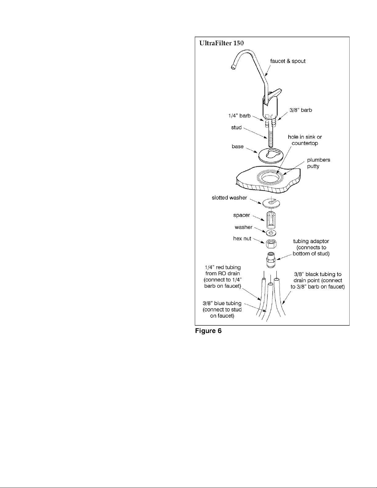
B. ASSEMBLE FAUCET
ULTRAFILTER 150
1. Loosely assemble the base, spacer, washer and
plastic nut onto the faucet stud.
2. Route the 1 / 4" red tubing through the sink or
countertop hole and connect to 1/4" barb on faucet.
3. Route the 3/8" black tubing through sink or the
countertop hole and connect to 3/8" barb on faucet.
4. Attach the 3/8" blue tubing to the faucet stud us
ing the tubing adaptor.
5. Lower faucet into place on the countertop, on the
underside of the countertop or sink slide the slotted
washer into place and tighten plastic nut. Tighten
the nut so the faucet cannot move, but do not over
tighten.
Problems, Questions? Call 1-800-426-9345 Kenmore Water Line
Page 8
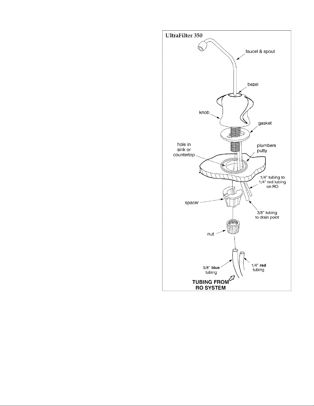
- STEP 3: INSTALL FAUCET (cont.)-
B. ASSEMBLE FAUCET
ULTRAFILTER 350
1. Remove the nut from the faucet threads.
2. Remove the spacer from the threads. To do this,
place a finger on either side of the threads and gently
press thumb against the bottom of the faucet threads
(where the quick connect is). The spacer should slide
past the stop.
3. Slide the two attached tubes through the sink or
countertop hole, aligning gasket under faucet base.
4. On the underside of the sink or countertop, slide
the spacer back onto the faucet threads. The spacer
should align with the tubing in the back. Tighten the
nut so the faucet cannot move, but do not overtigh
ten,
5. Connect tubing.
a. Connect the 3/8" blue tubing from the RO system
to the quick connect at the bottom of the faucet
threads.
Note: See page 16 for tubing connection instructions.
b. Connect the 3/8" tubing from the faucet to the
drain point (drain adaptor).
c. Connect the 1/4" red tubing (supplied with RO)
to the 1 / 4" tubing attached to the faucet using the
1 / 4" X 1 / 4" quick connector.
6. Remove the spout from the top of the faucet by
pulling it straight upward.
7. Remove the faucet knob by pinching the two lock
ing tabs inward and then pulling upward on the
knob while the tabs are pinched inward. See Figure 8.
8. Push the coin cell battery into the battery holder be
hind the circuit board. NOTE: the + side of the bat
tery goes against the gold metal bracket.
9. Replace the knob by centering it over the faucet
and aligning the channel on the inside of the knob
with the valve lever.
10. Lower the knob making sure the valve lever
slides into the channel, then make sure the top hole
in the knob is centered over the locking tabs.
11. Push the spout back into the top of the faucet so
that it is fully seated and push the bezel down until
fully seated. You may have to rotate the bezel until it
is in position to be fully seated.
Figure 7
8
Problems, Questions? Call 1-800-426-9345 Kenmore Water Line
Page 9

- STEP 3: INSTALL FAUCET (cont.)-
FAUCET ELECTRONICS
The faucet will measure the length of time the filters
have been installed (6 months). The faucet has an in
dicator LED that flashes to inform you of the status
of the filter.
Green - Filter is good. Red - Filters need replacing.
In order to reset the monitor time feature, the battery
should be removed for a minimum of five seconds
and then reinserted.
The battery needs to be replaced when indicater
LEDs no longer light. Use only 3 volt sealed lithium
batteries. Improper placement of battery could dam
age electronics. Use care when inserting battery to
align it correctly.
To change the battery, pull the spout and bezel from
the faucet base. The bezel will stay on the spout.
Pinch the two tabs (under bezel on faucet) with one
hand and with the other, pull up on the knob.
Change battery. Assemble the the knob, and spout
and bezel back onto the faucet base.
STEP 4: INSTALL RO ASSEMBLY
Fiang the assembly on the included hanger washers,
or lay on the cabinet floor, as desired.
1. Refer to Figure 9 for wall mounting. ITold the as
sembly up to the wall surface and mark locations for
the hanger washers. Distance needed is 7.2"
(approx. 7-7/32") apart.
2. Install hanger washers at least 15-1/2" up from the
cabinet floor, allowing room to remove sumps from
filter heads. Wood screws are provided, or obtain
other fasteners as needed.
Problems, Questions? Call 1-800-426-9345 Kenmore Water Line
Page 10

- STEP 5: INSTALL STORAGE TANK,
MAKE REMAINING TUBING CONNECTIONS
1. CONNECT DRAIN TUBING, FAUCET TO
DRAIN ADAPTER: Referring to Figure 10, run the
loose section of black 3/8" tubing from the faucet to
the drain adapter, with a black collet, installed on
page 6. Cut this tubing as needed to route in as
straight of a run as possible, without loops, dips,
low spots or kinks. Cut the end of the tubing square.
Then push all the way into the fitting. Pull on the tub
ing to be sure it's held firmly in the adapter fitting.
See page 16 for tubing connection instructions.
2. CONNECT TUBING TO WATER SUPPLY: Con
nect the feed (green) tube to the water supply fitting
installed on page 5. Connection to the fitting is as
described in Figure 14, page 16.
3. Move the storage tank into place next to the RO as
sembly. You can stand the tank upright, or lay it on
side. Apply no more than two wraps of Teflon tape
to the threads on the nipple at the top of the tank.
Eland tighten the other included tubing adapter fit
ting with the yellow collet onto the tank nipple, then
wrench 1/4 turn only. BE CAREFUE NOT TO
CROSS THREAD.
4. Run the 3 / 8" yellow tubing to the fitting installed
in step 3. Be sure the end of the tubing is cut square,
and insert all the way into the fitting. Again, pull on
the tubing to be sure it's held firmly in the fitting.
Figure 10
10
Problems, Questions? Call 1-800-426-9345 Kenmore Water Line
Page 11

- STEP 6: SANITIZING, PRESSURE TESTING & PURGING
SANITIZING
Sanitizing is recommended upon installation of the
RO system, and after servicing inner parts. It is im
portant for the service person to have clean hands
while handling inner parts of the system.
CA UTION: Be sure to remove the RO membrane and
both filter cartridges as follows, before sanitizing.
Chlorine ivill destroy the RO membrane cartridge.
1. Be sure the water supply to the RO is turned off,
and the RO faucet is open to relieve pressure.
2. Referring to Figure 12, page 14, remove the RO
membrane sump by twisting 1/4 turn left (^J). Re
move the RO cartridge from sump. Place the car
tridge in a
3. Be sure the o-ring seal is on the sump. Replace the
RO sump by turning to the right (C,) to lock.
4. Remove the postfilter sump, turning to the left.
Take the cartridge from the sump and place in the
plastic bag. Replace the sump by turning to the right
(t^) to lock.
5. Remove the prefilter sump and cartridge. Also
place this cartridge in the clean bag.
clean plastic bag.
6. If needed to clean, flush the prefilter sump with
fresh water. Then fill with water to about 1" from the
top. Add 1.0 ounce of chlorine (ordinary 5.25%
household bleach...Hilex, Clorox, etc.) and mix in the
water. Do not add chlorine first. Concentrated it will
attack plastics.
7. Carefully replace the sump on the prefilter head
and turn to the right (C,) to lock.
8. Slowly open the water supply to the RO.
9. Open the RO faucet by turning knob to the left.
10. Allow water to circulate through the RO system
until you smell the bleach odor at the faucet. Then
close the faucet and allow the RO to stand idle for 20
minutes.
11. After the 20 minutes open the RO faucet and run
water until the bleach odor is gone.
12. Turn off the water supply to the RO.
13. Be sure your hands are clean. Then, repeat steps
1-5 and 7, only replace all cartridges.
Important: Refer to Figure 12, page 14, and to page 15
when replacing cartridges. The prefilter (left side)
cartridge and the postfilter (right side) have puple
end caps.
PRESSURE TESTING
1. Do the preceding sanitizing procedures before
pressure testing.
2. Open the water supply shutoff valve to the RO.
3. Open the main water supply valve and several
house faucets to purge air from the system. Close
faucets when water runs smooth.
PURGING RO MEMBRANE
Important purging instructions: The RO cartridge
contains a food grade preservative that should be rinsed
before using water from the system. The preserva
tive will give product water an unpleasant taste and
odor.
4. hi about 2 hours, pressure will start to build in the
RO system. Then, carefully check all fittings and con
nections for water leaks. Correct leaks if any are
found.
Note: When the system is first pressurized, water
may "spurt" from the faucet airgap hole until air is
expelled from the RO system.
1. Allow the storage tank to fill for about 4 hours.
Then open the RO faucet until the tank is empty and
flow stops. Close the RO faucet.
2. Repeat step 1 five more times (for a total of 6) to
purge the RO system. Then the RO system is ready
to make product water for use.
11
Problems, Questions? Call 1-800-426-9345 Kenmore Water Line
Page 12

- HOW YOUR REVERSE OSMOSIS SYSTEM WORKS
PREFILTER
Water from the cold supply pipe enters the RO as
sembly prefilter first (Figure 10, page 10, and sche
matic, page 13).
The prefilter has a replaceable sediment cartridge
with activated carbon in its composition. The car
tridge (10 micron) removes sand, silt, dirt, other sedi
ments, and up to the ppm of chlorine shown in the
specifications from the feed water (page 18). Chlo
rine will destroy the RO membrane. Filtered, clean,
chlorine- free water flows from the prefilter, to the RO
membrane cartridge.
IMPORTANT: See prefilter maintenance, page 14.
REVERSE OSMOSIS (RO) CARTRIDGE
The RO cartridge is a tightly wound special mem
brane. The membrane removes the dissolved solids
and organic matter when water is forced through the
cartridge. Fligh quality product water (about one
ounce per minute) exits the RO cartridge and goes to
the storage tank, or to the postfilter and RO faucet.
Reject water, with the dissolved solids and organic
matter, is routed through the flow control and to the
drain.
STORAGE TANK
The storage tank holds up to 2.3 gallons of product
water. A diaphragm inside the tank keeps water
pressurized to about 30 psi, when the tank is full, to
provide fast flow to the RO faucet. The tank, when
empty, is pressurized to 5 - 7 psi.
POST FILTER
After leaving the storage tank, but before going to the
RO faucet, product water goes through the post filter.
The post filter is an activated carbon type filter. Any
remaining tastes and odors are removed from the
product water. Taste-free, odor-free, clean, high
quality drinking water is available for use.
FAUCET
The sink or countertop faucet has a hand operated
knob to access drinking water. An air-gap is built
into the faucet drain water connection to comply
with plumbing codes.
FAUCET ELECTRONICS (UltraFilter 350)
The RO system will monitor the length of time the fil
ters have been installed. The faucet has an indicator
light that flashes to inform you of the status of the fil
ters.
Green - Filters are good. Red - Filters need to be re
placed after 6 months of time has passed.
SHUTOFF ASSEMBLY
To conserve water, the drinking water system has an
automatic shutoff system. When the storage tank has
filled to capacity,
closed, pressure closes the shutoff to stop flow to
drain. Pressure in the storage tank is about half of the
water supply pressure. After drinking water is used,
and pressure in the system drops, the shutoff opens
to allow water flow again.
A check valve (Figure 16) is located in the RO man
ifold, above the center sump. The check valve pre
vents a backward flow of product water from the
storage tank. A backward flow could rupture the RO
membrane.
Water flow through the RO membrane is regulated
by the flow control. It maintains the desired flow rate
to obtain the highest quality drinking water. The
flow control is located in the end of the 1 / 4" red drain
tubing, at the RO manifold drain port.
and the drinking water faucet is
CHECK VALVE
FLOW CONTROL
12
Problems, Questions? Call 1-800-426-9345 Kenmore Water Line
Page 13

- HOW YOUR REVERSE OSMOSIS SYSTEM WORKS
REVERSE OSMOSIS WATER FLOW SCHEMATIC
Figure 11
PRODUCT
WATER
^FAUCET
gravity
drain
PRODUCT WATER
BLACK
■CZH
AUTOMATIC
WATER GREEN
IN
---------------
SHUTOFF
^
____
red
drain flow
control
YELLOW
o-»>
PRODUCT
WATER
STORAGE
PREFILTER MEMBRANE POSTFILTER
RO
- CARE OF YOUR REVERSE OSMOSIS SYSTEM
To keep your reverse osmosis system operating and
producing high quality water, you must make sure
supply water is always within the limits shown in the
specifications. Good supply water (soft water is rec
ommended) helps to assure longer life from the RO
membrane cartridge, prefilter and postfilter car
tridges. However, each of these will wear out in time
and need replacement.
This reverse osmosis system contains a replace
able treatment component critical for effective
removal of total dissolved solids. The monitor
faucet feature provides continuous analysis of the
systems performance. For systems not equipped
with the monitor faucet function, it is highly
recommended that you have your water tested at
least every 6 months to verify your system is
performing properly. Test kits are available by
calling 1-800-826-8553 ext. 47, or check the water
testing section of your local phone directory.
If the RO assembly is wall mounted, you may be able
to replace parts with the assembly left on the wall. If
not, simply lift the RO assembly from the mounting
washers and lay on the cabinet floor when replacing
the prefilter and post filter cartridges and RO mem
brane.
Note: To prevent spillage, place a container under the
RO assembly, or put the RO assembly in a container
to catch the water.
CAUTION; Before disconnecting parts, be sure to
close the ivater supply valve to the RO.
Problems, Questions? Call 1
13
■800—426-
■9345 Ken more Water Line
Page 14

- CARE OF YOUR REVERSE OSMOSIS SYSTEM
PREFILTER AND POST FILTER CARTRIDGES
You must replace the prefilter cartridge often to pro
tect the RO membrane from being destroyed by chlorine,
and/or from plugging with sediments in your water
supply. If the water supply contains both chlorine
and sediments, replace the prefilter cartridge at least
every 6 months of product water use. Replace more
often than 6 months if it begins to plug with sedi
ments.
If the water has sediments only, with no chlorine, you
may notice a slower making of product water as the
prefilter collects the sediments. When this occurs, re
place the prefilter cartridge. Also replace the post filter
cartridge.
To replace the filter cartridges (see Figure 12):
1. Turn off the water supply and open the RO faucet
to relieve pressure.
2. Remove (turn to the left) both sumps from the filter
heads. Be careful.. .the sumps are full of water.
3. Remove and discard the inner cartridges in a prop
er manner. Flush the insides of the sumps with fresh
water.
Do not lose the large o-ring seals.
4. Insert new cartridges with o-ring*^ seals towards
the top, and with lubricated* o- rings in place, turn to
the right to reattach the sumps.
5. Remove and replace batteries to reset counter and
timer, (monitor models).
*Note: Use a lubricant approved for use on a potable
water supply.
14
Problems, Questions? Call 1-800-426-9345 Kenmore Water Line
Page 15

- CARE OF YOUR REVERSE OSMOSIS SYSTEM
RO MEMBRANE CARTRIDGE
The life of the RO membrane cartridge depends
mostly on the pH of the supply water to the RO sys
tem (see specifications). Cartridge life is shorter with
higher pH. For example, if supply water pH is from 6.8
to 7.7, the cartridge may last for well over one year: Hoioever, cartridge life may be as short as 6 months if the pH
is as high as 8.5 to 10. Higher pH weakens the cartridge
membrane and causes pin-hole leaks.
It's time to replace the RO cartridge when the pro
duction rate and/or quality of product water drops.
Product water may begin to taste different or bad, in
dicating solids and organics are passing through the
RO membrane. To be sure it is the RO cartridge, re
place the prefilter and postfilter cartridges first.
To replace the RO cartridge (see Figure 12):
1. Turn off the water supply and open the RO faucet
to relieve pressure.
2. Remove (turn to the left) the sump from the filter
head. Be careful. . .the sump is full of water.
3. Remove and discard the RO cartridge in a proper
manner. Flush the insides of the sump with fresh wa
ter. Do not lose the large o-ring seals.
FLOW CONTROL
The flow control is vital for proper operation of the
RO membrane cartridge. The control keeps water
flow through the membrane at the needed rate to ob
tain the best quality product water.
Periodically check the flow control to be sure the
small hole through it is clean and unrestricted.
Note: Sanitizing is recommended after servicing in
ner parts of the system (see page 11).
4. Insert new RO cartridges with o-ring seals to
wards the top, and with lubricated o-ring in place,
turn to the right to reattach the sump.
5. Remove and replace batteries to reset counter and
timer, (monitor models).
6. Purge the RO membrane cartridge follaiuing instruc
tions on page 11.
15
Problems, Questions? Call 1-800-426-9345 Kenmore Water Line
Page 16

- CARE OF YOUR REVERSE OSMOSIS SYSTEM
TUBING CONNECTION
(all push- in fitting locations)
This RO system includes push- in fittings for quick
tubing connection at most locations. If working with
the fittings, do the following.
Connection (Figure 14):
1. Use a sharp cutter or knife to cut the end of tubing
square.
2. Inspect the end (about 1") of the tubing to be sure
there are no nicks, scratches or other rough spots. If
needed, cut the tubing again.
3. Push tubing through the collet and all the way into
fitting. Full engagement is 11/16" for 1/4" tubing,
and 3 / 4" for 3 / 8" tubing.
If using tubing other than tubing supplied with the
system, be sure it is of high quality, exact size and
roundness with a smooth surface.
Tubing correctiy cut and connected
cut tubing square
collet.
CAUTION
DO NOT USE VINEGAR OR OTHER ACID BASED
CLEANERS ON THIS RO SYSTEM. THEY WILL
DEGRADE SOME RO SYSTEM PARTS. ALWAYS
USE SOAP AND WATER.
I-.
r'
This reverse osmosis system contains a replaceable
. J
■n
treatment component critical to the efficiency of the
system. Replacement of the reverse osmosis compo
nent should be with one of identical specifications,
as defined by the manufacturer; to assure the same
efficiency and contaminant reduction performance.
AUTOMATIC SHUTOFF SERVICE
If the shutoff assembly requires service, be sure to
reassemble parts exactly as shown in Figure 16.
end of tubing round and
smooth, with no cuts,
nicks or flat spots
11/16" (1/4" tubing)
engagement
3/4^' (3/8" tubing)
Figure 14
To Disconnect Tubing (Figure 15): Push the collet in
ward and hold with a finger while pulling the tubing
out.
Changing Collet and O-ring (Figure 15):
1. With a small screwdriver remove the collet and o
ring from the fitting. Be careful not to scratch the in
ternal walls of the collet port.
2. Be sure the port is clean, then lubricate and insert
the o-ring seal to the bottom of the port.
3. Push the collet inward until it locks in place.
Figure 16
16
Problems, Questions? Call 1-800-426-9345 Kenmore Water Line
Page 17

- CARE OF YOUR REVERSE OSMOSIS SYSTEM
REVERSE OSMOSIS SYSTEM CARE GUIDE
MODEL NOs. 625.385700 & 625.385720
1. AT LEAST every 6 months, replace the prefilter and postfilter cartridges or when red LED flashes,
2. Replace the RO membrane cartridge when the percent rejection of total dissolved solids (TDS) is less than shown
in the specifications (see B, below).
3. Replace the battery once per year.
If any of the following occur before the 6 months, replace as directed.
A. Slow Making of Product Water: Replace the prefilter cartridge.
If the production rate does not improve, replace the post filter car
tridge and RO membrane cartridge.
B. High Total Dissolved Solids (TDS) in Product Water: You can
get a free TDS test through some Sears retail stores or service
departments. If the store or service department does not have a
TDS meter, you can send treated and untreated water samples to
a water analysis lab for testing. It Is important to test both the
treated and untreated water to determine system performance. If
the TDS is not within the system’s performance guidelines,
replace the prefilter, post filter and RO membrane cartridges.
OTHER TROUBLESHOOTING
PROBLEM CAUSE CORRECTION
Chlorine taste and/or
odor in the RO product
water
The ppm of chlorine In your water supply
exceeds maximum limits, and has de
stroyed the RO membrane.
C. Chlorine Taste and lor Odor: Replace the prefilter, post filter and
RO membrane cartridges.
If the water supply contains more than 2.0 ppm of chlorine, addi
tional filtering of the water supply to the RO is needed. Correct
this condition before doing maintenance on the RO system.
The prefilter is no longer removing chlo
rine from the water supply.
Other taste and/or odor Post filter expended. Replace the post filter cartridge. If taste and odor persists, re
RO membrane cartridge expended.
Replace the prefilter, post filter and RO membrane cartridges.
place the prefilter cartridge and RO membrane cartridge.
Contamination in product water storage. Use sanitizing procedures. Replace the post filter cartridge.
System makes product
water too slowly
System makes lower
amount of product water
than usual
High total dissolved sol
ids (TDS) in product wa
ter
Water supply to the RO system not within
specifications.
Prefilter or RO membrane cartridges
plugged with sediments.
Storage tank air-charge less than 5-7
psi.
Water supply to the RO system not within
specifications.
RO membrane cartridge expended. Replace the prefilter, postfilter and RO membrane cartridges,
Increase water pressure, precondition the water, etc., as needed
to conform before doing maintenance on the RO system.
Replace the prefilter cartridge. If rate does not increase, replace
the postfilter cartridge and RO membrane cartridge.
Open RO faucet and drain tank until flow slows to a drip. Keep
faucet open and check tank pressure. If low, pressurize to 6 psi.
Close faucet to refill the tank.
Increase water pressure, precondition the water, etc., as needed
to conform before doing maintenance on the RO system.
flow control, and screen.
Water leaking from fau
cet airgap hole
Drain side of faucet airgap (3/8” tubing)
plugged, restricted, or incorrectly con
Inspect and eliminate restriction or plug. Refer to installation
instructions for proper drain connection.
nected to drain point.
Continual water flow to
drain
Faucet LED indicator
light does not function af
ter battery change
Continual water flow to
drain and no product wa ter
Faucet LED indicator
light flashing red
Check valve or automatic shutoff assem
bly plugged, restricted or parts worn
Batteries dead. Replace with new batteries.
Batteries installed Incorrectly.
Missing flow restrictor in red drain tube or
its corresponding port.
Filters need replacing. Change filters.
Clean, repair or replace as needed.
Install batteries correctly.
Replace flow restrictor.
Note: Sanitizing is recommended after servicing inner parts of the system(see page 11).
Problems, Questions? Call 1-800-426-9345 Kenmore Water Line
Page 18

- DIMENSIONS and SPECIFICATIONS -
15”
Supply water pressure limits
Supply water temperature limits............................................ 40 - 100 °F
Maximum total dissolved solids (TDS) ................................. 2000 ppm
Maximum water hardness @ 6.9 pH..................................... 10 gpg
Maximum iron, manganese, hydrogen sulfide
Chlorine in water supply (max. ppm)
Supply water pH limits (pH) .................................................. 4-10
Product (quality) water, 24 hours
Waste water per gallon of product water
Percent rejection of TDS, minimum (new membrane)
Storage tank capacity (max.)
Automatic shutoff control....................................................... yes
Efficiency (2) ......................................................................... 8%
Recovery cs).......................................................................... 16 %
STORAGE
TANK
9” dia.
.................................................
......................
...................................
CD
...................................... 14 gal.
CD
..........................
CD
90 - 95
...............................................
11”
40 -- 100 psi
0
2.0
5 gal.
2.3 gal.
13”
Metric
280 - 690 kPa
5 - 40°C
53 liters
18.9 liters
8.7 liters
This system conforms to NSF/ANSI 58 for the specific performance claims as verified and sub
stantiated by test data.
(D
Feed water supply at 50 psi, 77°^ and 750 TDS - Quality water production, amount of waste
water and percent rejection all vary with changes in pressure, temperature and total dissolved
solids.
(2) Efficiency rating means the percentage of the influent water to the system that is available to
the user as reverse osmosis treated water under operating conditions that approximate typical
daily usage.
(3) Recovery rating means the percentage of the influent water to the membrane portion of the
system that is available to the user as reverse osmosis treated water when the system is operated
without a storage tank or when the storage tank is bypassed.
18
Problems, Questions? Call 1
■800—426-
9345 Kenmore Water Line
Page 19

- REMOTE INSTALLATION LOCATIONS -
Possible remote locations for the RO nearby the
kitchen or bathroom sink include; (1) a basement area
underneath the sink, and (2) an adjacent room or
closet. Longer lengths of tubing (see parts list on
page 20) may be needed.
You can run the drain tubing directly to one of several
suitable open drain points, as shown below, bypas
sing the faucet airgap and p-trap drain. This type of
drain is the preferred over the p-trap drain adapter.
Check your local codes. Always be sure to provide an
air gap between the end of the hose and the drain
point.
19
Problems, Questions? Call 1-800-426-9345 Kenmore Water Line
Page 20

- REPAIR PARTS -
Kenmore Reverse Osmosis Drinking Water System,
Page 21

- REPAIR PARTS -
Kenmore Reverse Osmosis Drinking Water System, Model Nos. 625.385700 & 625.385720
Key
No.
1 7221128 Sump {3 req.)
2 7223633 O-Ring, 2-1/4” X 2-1/2” (3 req.)
3
4
5 7234317
6 7229451 Screw {4 req.)
7 7229532 Automatic Shut-off Cover
8
9
■
10
11 42-38476 Filter, Carbon Block (2 pack)
12 7267962
13 7208544 Connector, 1/4” X 1/4”
14
15 7205326
16 7251034
17
Part
Number
9006062 Screw (2 req.)
9041700
7250876 Diaphragm Kit
7234325 Plunger & Spacer Ring Kit
7095030
7265766
7208560
7208489
Hanger Washer (2 req.)
Check Ball Assembly
Cone Screen
Flow (Control) Insert
RO Membrane Cartridge
Connector, 1/4” X 3/8”
Storage Tank
Connector, 1/4 NPT x 3/8 Tube
Drain Adaptor
Description of Part
Key
No.
18 7227310 Tee, Feed Adaptor
19 Faucet, Model 625.385700
20 7234333
21 7209566 Push-in Fitting Kit, 1/4”
22 7255101 Manifold, incl. key nos. 5 thru 9
■
■
■
■
■
■
■
■
■
Part
Number
7266584
7209574 Push-in Fitting Kit, 3/8” •>
7266568
Optional Accessories and Tubing
7161823
7161784
7157280 Tubing, 3/8” X 20’ - white [D-f
7161750 Tubing, 3/8” X 100’ - white Hj-f
7122798
42-34707 Suppl. Storage Tank, 3.2 gallon >
7123613
Faucet, Model 625.385720
Cover
Owner’s Manual
Faucet Battery, Model 625.385720
only, purchase locally, Duracell
DL2032 or Eveready ECR2032
Tubing, 1/4” X 20’ - white [D-f
Tubing, 1/4” X 100’ - white [T]>
Optional Drain Adaptor -f
Grease for 0-Rings >
Description of Part
ffl Tubing for remote installations (not included) see page 19, also direct replacement for colored lengths of tub
ing.
A0 See page 20 for use locations - Note: This o-ring and collet are for replacement in the manifold housing only.
They do not fit the other push-in fittings, key nos. 13, 14, 15, 17, 18 and 19.
> not included
■ not illustrated
Problems, Questions? Call 1
21
■800—426- 9345 Kenmore Water Line
Page 22

NOTES -
Problems, Questions? Call 1
22
■800—426- 9345 Kenmore Water Line
Page 23

NOTES -
Problems, Questions? Call 1
23
■800—426-
9345 Kenmore Water Line
Page 24

OWNER’S
MANUAL
MODEL NO.
UltraFilter 150
625.385700
UltraFilter 350
625.385720
The model number of
your reverse osmosis
system is found on the
rating decal. This decal is
on the back of the R. O.
sump.
When requesting service
or ordering parts, always
provide the following in
formation:
Reverse Osmosis Drinking Water System
Get it fixed, at your home or ours!
Yoyr Home
For repair-- in your hótiné-óf all major brand appliances,
lawn and garden equipment, or heating and cooling systems,
no matter who made it, no niiatter who sold Itl
For the replacement parts, accessories and
owner’s manuals that you need to do-it-yourself.
For Sears professional inslaliation of home appílánces
and items like garage door openers and water heaters
1 -SOO-4-MY-HÓIVtE ■ {1 ..,^00-469.4653)
Cáii snytime, day Of nighi (U.S A arid Canacia)
www.seafs.com. wwwv.sears.ca
Our Home
For .repair of carry-in items ike vacuums, lawn equipment,
and etectronics, catl or go on-line fo.r the location of your nearest
S'ears Parte & Repair Center,
t it :2.
Cali anytime, day or night. (U S.A, only)
www.8ears.com
To purchase a protection agreement {U.S.A.)
or maintenance agree.ment (Canada) on a pro.duct serviced by Sears:
1 -800-827-6655 -u u a . 1 -800-361 -6665 (Canada)
♦ Product Type
♦ Model Number
♦ Part Number
♦ Part Description
www.KenmoreWater.com
Sears, Roebuck and Co., Hoffman Estates, IL 60179 U.S.A.
Para pedir servido de reparación
9 dornicilio. y para ordenar pie'zas:
íD R&UKfered 1
fí^arí|.{ít! m (
1-8S8-SU-HOGAR '
(1-8B8-784-6427)
Mask Pi-SCfSTS., RíSSílJUC.f
ivvi-.'c.it i'to Sefdiaiod.i>Sé7í!S., F
íiuHñ: nmb&Gk atuí Do.
Au Canadá póur service en frángáii
1-800-LE-FOYER
(1-80P-533-69-37)
 Loading...