

Kenmore 625.385560 User Manual
Part No.7287946 (Rev. E 10/27/06)
• Warranty
• Installation
• How It Works
• Care Of
• Specifications
• Repair Parts
Reverse Osmosis
System
Sears, Roebuck and Co., 3333 Beverly Road, Hoffman Estates, IL 60179 USA
www.KenmoreWater.com
Repair or Parts ? Call toll free 1-800-366-7278
See back cover for other Sears service numbers.
Caution:
Read and follow all safety rules and operating
instructions before first use of this product.
MODEL NO. 625.385560
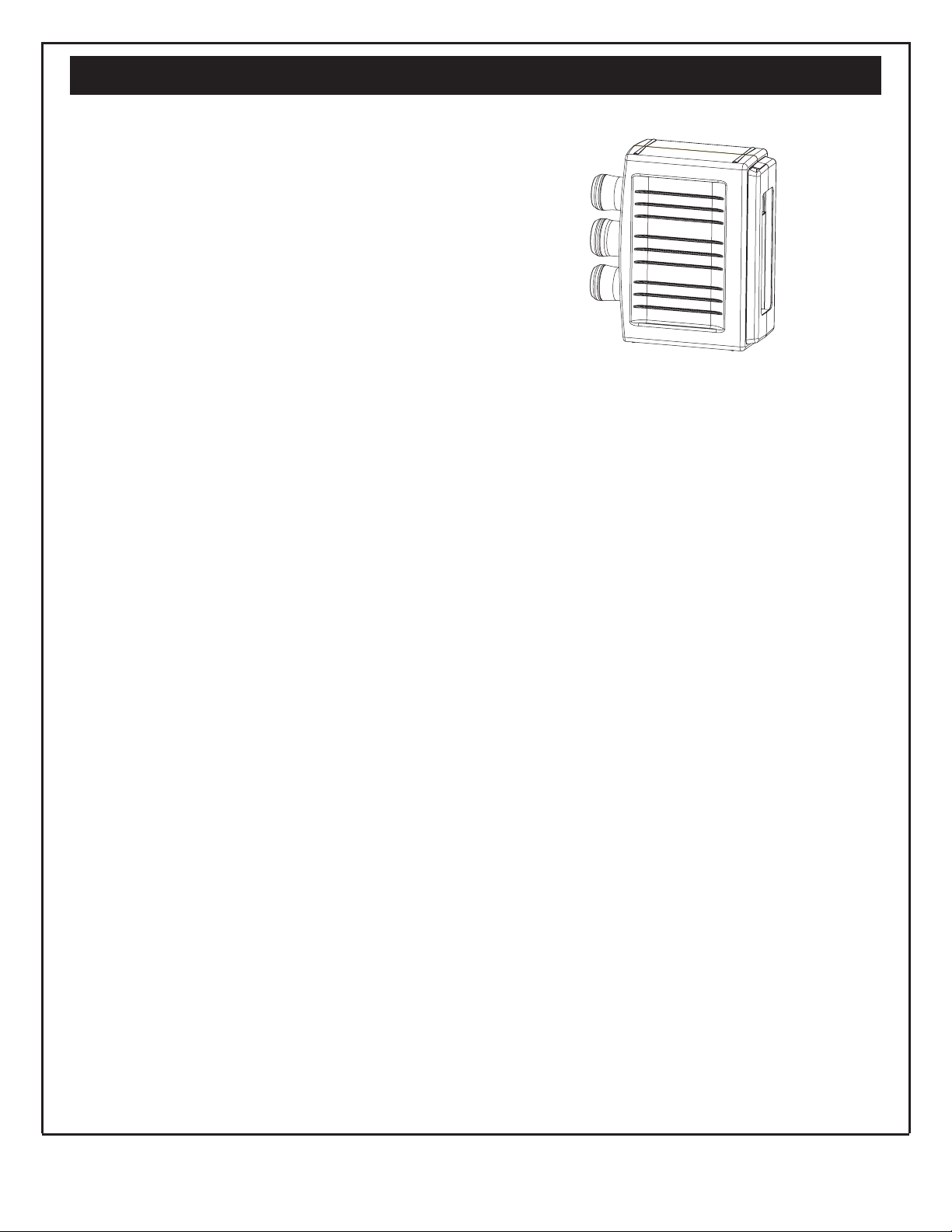
UltraFilter 650
OWNER'S MANUAL
PRINTED IN U.S.A.
E L I T E
SAVE THIS MANUAL
Questions ?
Visit www.KenmoreWater.com
or call toll free 1-800-426-9345 (M - F, 7AM - 8 PM CST)
System Tested and Certified by NSF International against NSF/ANSI
Standard 42 and 58. See perfomance data sheet for details.
2
Questions? Call The Kenmore Water Line 1-800-426-9345 or visit KenmoreWater.com
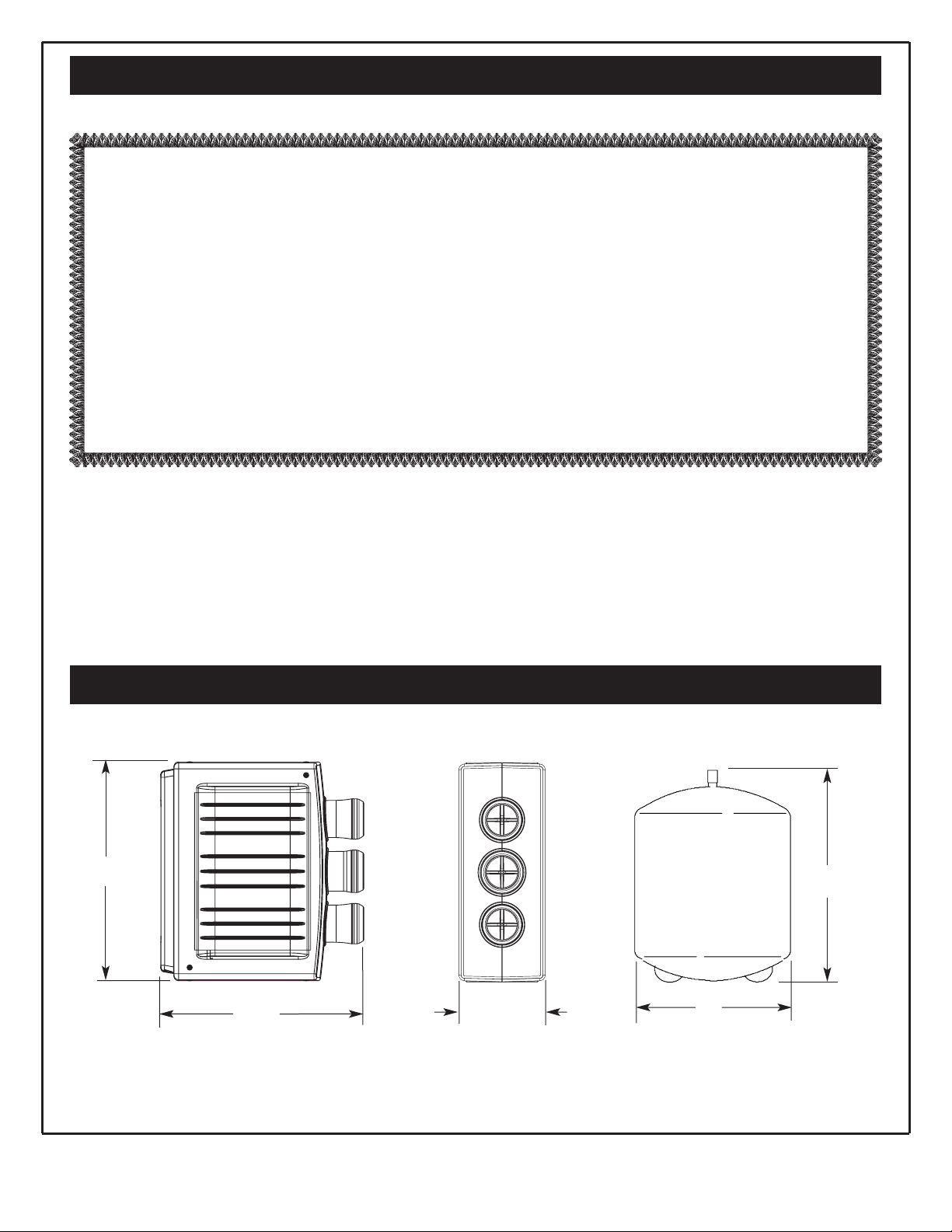
14”
13”
11”
5-1/2”
14”
Dimensions
Warranty
ONE YEAR FULL WARRANTY ON REVERSE OSMOSIS SYSTEM
When installed, operated and maintained according to all instructions supplied with the product, if this
Reverse Osmosis System fails due to a defect in material or workmanship within one year from the date of
purchase, call 1-800-4-MY-HOME to arrange for free repair (or replacement if repair proves impossible).
This warranty does not include filter cartridges or the Reverse Osmosis membrane, which are expendable
items.
This warranty applies only while this product is in use in the United States.
This warranty gives you specific legal rights, and you may have other rights which vary from state to state
.
Sears, Roebuck and Co., Hoffman Estates, IL 60179

3
Questions? Call The Kenmore Water Line 1-800-426-9345 or visit KenmoreWater.com
Table of Contents
Safety Guides
Unpack and Check Shipment . . . . . . . . . . . . . . . . . . . . . . . . . . . . . . . . . . . . . . . . . . . . . . . . . . . . . . . . . . . . . . . . . . . . . . . . . . . . .4
What Your Reverse Osmosis System Will do . . . . . . . . . . . . . . . . . . . . . . . . . . . . . . . . . . . . . . . . . . . . . . . . . . . . . . . . . . . . . . .5
Plan Your Installation . . . . . . . . . . . . . . . . . . . . . . . . . . . . . . . . . . . . . . . . . . . . . . . . . . . . . . . . . . . . . . . . . . . . . . . . . . . . . . . . . .5-6
Overview and Site Preparation . . . . . . . . . . . . . . . . . . . . . . . . . . . . . . . . . . . . . . . . . . . . . . . . . . . . . . . . . . . . . . . . . . . . . . . . . . .7
Step 1-Install Supply Water Fitting . . . . . . . . . . . . . . . . . . . . . . . . . . . . . . . . . . . . . . . . . . . . . . . . . . . . . . . . . . . . . . . . . . . . . . . .8
Step 2-Install Reverse Osmosis Drain . . . . . . . . . . . . . . . . . . . . . . . . . . . . . . . . . . . . . . . . . . . . . . . . . . . . . . . . . . . . . . . . . . .9-10
Step 3-Install Reverse Osmosis Filter Assembly . . . . . . . . . . . . . . . . . . . . . . . . . . . . . . . . . . . . . . . . . . . . . . . . . . . . . . . . . . . .11
Step 4-Install Storage Tank . . . . . . . . . . . . . . . . . . . . . . . . . . . . . . . . . . . . . . . . . . . . . . . . . . . . . . . . . . . . . . . . . . . . . . . . . . . . . .11
Step 5-Install Reverse Osmosis Faucet . . . . . . . . . . . . . . . . . . . . . . . . . . . . . . . . . . . . . . . . . . . . . . . . . . . . . . . . . . . . . . . . . .12-13
Step 6-Connect Tubes . . . . . . . . . . . . . . . . . . . . . . . . . . . . . . . . . . . . . . . . . . . . . . . . . . . . . . . . . . . . . . . . . . . . . . . . . . . . . . . .14-15
Step 7-Sanitize, Pressure Test, Purge System . . . . . . . . . . . . . . . . . . . . . . . . . . . . . . . . . . . . . . . . . . . . . . . . . . . . . . . . . . . .16-17
How Your Reverse Osmosis Water System Works . . . . . . . . . . . . . . . . . . . . . . . . . . . . . . . . . . . . . . . . . . . . . . . . . . . . . . .18-19
Maintenance . . . . . . . . . . . . . . . . . . . . . . . . . . . . . . . . . . . . . . . . . . . . . . . . . . . . . . . . . . . . . . . . . . . . . . . . . . . . . . . . . . . . . . . .20-21
Specifications . . . . . . . . . . . . . . . . . . . . . . . . . . . . . . . . . . . . . . . . . . . . . . . . . . . . . . . . . . . . . . . . . . . . . . . . . . . . . . . . . . . . . . . . . .22
Troubleshooting . . . . . . . . . . . . . . . . . . . . . . . . . . . . . . . . . . . . . . . . . . . . . . . . . . . . . . . . . . . . . . . . . . . . . . . . . . . . . . . . . . . . .24-25
Exploded View & Parts List . . . . . . . . . . . . . . . . . . . . . . . . . . . . . . . . . . . . . . . . . . . . . . . . . . . . . . . . . . . . . . . . . . . . . . . . . .26-27
B Read all steps and guides carefully before installing
and using your reverse osmosis system. Follow all
steps exactly to correctly install. Reading this manual
will also help you to get all the benefits from the
reverse osmosis system.
B Do not attempt to use this product to make safe
drinking water from non-potable water sources. Do
not use the system on microbiologically unsafe water,
or water of unknown quality without adequate disinfection before or after the system. This system is certified for cyst reduction and may be used on disinfected water that may contain filterable cysts.
B Check with your local public works department for
plumbing and sanitation codes. You must follow their
guides as you install the system. Follow your local
codes if they differ with guides in this manual.
B This system shall only be used for arsenic reduction
on chlorinated water supplies containing detectable
residual free chlorine at the system inlet. Water systems using an inline chlorinator should provide a one
minute chlorine contact time before the RO system.
B This system is acceptable for treatment of influent
concentrations of no more than 27 mg/L nitrate and 3
mg/L nitrite in combination measured as N and is certified for nitrate/nitrite reduction only for water supplies with a pressure of 280 kPa (40 psig) or greater.
B The reverse osmosis system works on water pressures
of 40 psi (minimum) to 100 psi (maximum). If your
house water pressure is over the maximum, install a
pressure reducing valve in the water supply pipe to
the reverse osmosis system.
B Do not install the reverse osmosis system outside, or
in extreme hot or cold temperatures. Temperature of
the water supply to the reverse osmosis system must
be between 40_F and 100_F. Do not install on hot
water.
B Read the other limits (pH, hardness, etc.) in the speci-
fications and be sure your water supply conforms.
B The reverse osmosis membrane contains a preserva-
tive for storage and shipment. Be sure to purge as
instructed on page 17 before using product water.
4
Questions? Call The Kenmore Water Line 1-800-426-9345 or visit KenmoreWater.com
Unpack and Check Your Carton
INSPECT SHIPMENT
Your Reverse Osmosis Drinking Water System is shipped
complete in one carton. Remove all items from your
shipping carton.
Check all items against the packing list below. Note any
items lost or damaged in shipment. Note any damage to
the shipping carton. Refer to the exploded view and
parts list in the back of the manual for the part names
and numbers of missing or damaged items. If problems
exist, refer to the website or the toll free number listed
throughout this manual.
Keep the small parts in the parts bag until you are ready
to install them.
NOTE: Codes in the state of Massachusetts require
installation by a licensed plumber and do not permit the
use of saddle valves.
If you live in the state of Massachusetts, review plumbing code 248-CMR of the Commonwealth of
Massachusetts before proceeding with the installation.
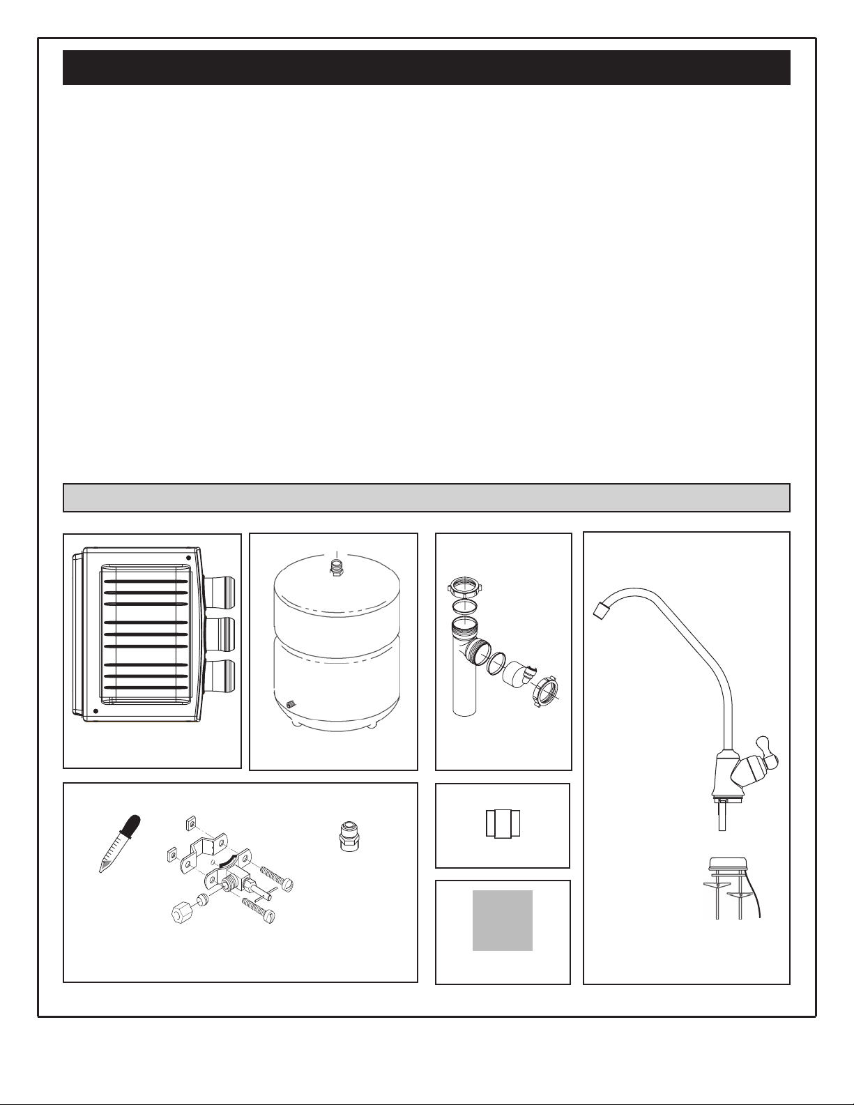
Packing List
Water Storage Tank
Reverse Osmosis Assembly
Bag Assembly
Bag Assembly
Bag Assembly
Drain Adaptor Kit
Reverse Osmosis Faucet Assembly
Dropper
Tank
Connector
Thread Sealing Tape
Nitrate/Nitrate Test kit
Saddle
Valve
5
Questions? Call The Kenmore Water Line 1-800-426-9345 or visit KenmoreWater.com
What Your Reverse Osmosis System Will Do
Plan Your Installation
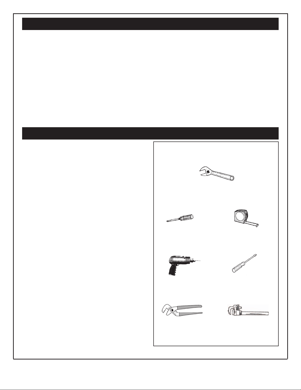
Tools Needed
Adjustable Wrench
Phillips Screwdriver
Drill & Drill bits, if required
Large Adjustable Jaw Pliers or Pipe Wrench
Flathead Screwdriver
Tape Measure
Your Reverse Osmosis (RO) Drinking Water System is a
water treatment unit. It uses household water pressure to
reverse a natural physical process called osmosis. Water,
under pressure, is forced through a semi-permeable
membrane where minerals and impurities are filtered
out. Clean drinking water goes to the faucet or storage,
while minerals and impurities are sent to the drain with
RO waste water. The minerals and impurities are measured in water as total dissolved solids (TDS).
The system includes replaceable pre and postfilter sediment-carbon cartridges. The prefilter reduces sand, silt,
dirt, rust particles, other sediments, and chlorine from
the water supply before it can enter the RO membrane.
The postfilter reduces any tastes and/or odors that may
remain in the water, after passing through the RO membrane, and just before going to the RO faucet. To prevent
water waste, an automatic shutoff valve closes when the
RO faucet is closed and the storage tank is full.
Your reverse osmosis system gives you a continuous
supply of sparkling clear, delicious water for drinking,
cooking and other uses. Foods will look and taste better
too. Having high quality RO product water at your fingertips eliminates the need to buy bottled water. The
storage tank holds over 2 gallons of RO product water
for your needs.
PLAN YOUR INSTALLATION
It is recommended to read through the entire manual
before beginning your installation. Follow all steps exactly. Reading this manual will also help you get all the
benefits from your system.
Your Reverse Osmosis Drinking Water System can be
installed under a sink or in a remote location. Typical
remote sites are a laundry room or utility room. Review
the location options below and determine where you are
going to install your system.
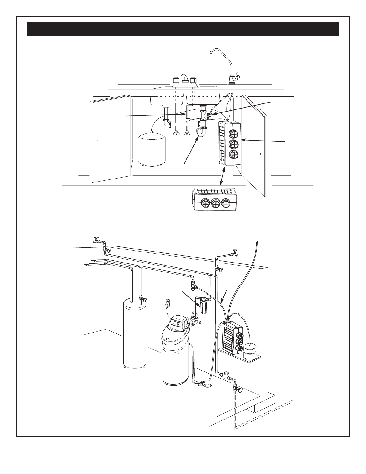
UNDER THE SINK LOCATION
The Reverse Osmosis Filter Assembly and storage tank
are normally installed in a kitchen or bathroom sink cabinet. See Figure 2.
A suitable drain point is needed for reject water from the
Reverse Osmosis filter.
REMOTE LOCATION
You can also locate the Reverse Osmosis Filter Assembly
and storage tank in a remote location away from the
Reverse Osmosis Faucet. You will need a nearby water
source and drain point.
See Figure 3.
CHECK SPACE REQUIREMENTS
Check size and position of items for proper installation
into location chosen.
TOOLS NEEDED
Review the tools needed list. See Figure 1. Gather needed tools before proceeding with the installation. Read
and follow the instructions provided with any tools listed here.
Figure 1
6
Questions? Call The Kenmore Water Line 1-800-426-9345 or visit KenmoreWater.com
Plan Your Installation
Figure 2
Figure 3
Cold Water
Supply
Sink Drain P-Trap
HOT COLD
Storage
Tank
Typical Under Sink Installation
Typical Remote Installation
All install parts included in package.
Drain Adapter
for Reverse
Osmosis Waste
Water
Reverse
Osmosis
Assembly
OR
Outside Faucet
(Hard Water)
Outside Faucet
(Hard Water)
Soft, Cold Water
Soft, Hot
Water
Water
Heater
Water
Softener
Main
Shutoff
Valve
Storage
Tank
Reverse
Osmosis
System
Hard
Water to
House
Water
Meter
Additional Parts required.
To
Reverse Osmosis
Air Gap Faucet
Air Gap
Soft, Cold
Water to
RO Sys.
Hard Water House Line
Sediment
Filter
7
Questions? Call The Kenmore Water Line 1-800-426-9345 or visit KenmoreWater.com
Overview and Site Preparation
Figure 4
OVERVIEW
There are seven easy steps to installing your Drinking
Water system. They are as follows:
STEP 1 - Install Cold Water Supply fitting
STEP 2 - Install Drain Adapter
STEP 3 - Install Reverse Osmosis Assembly
STEP 4 - Install Storage Tank
STEP 5 - Install Reverse Osmosis Faucet
STEP 6 - Connect Tubing
STEP 7 - Sanitize, Pressure Test, Purge System
These steps are explained in detail over the next few
pages.
It is recommended to read through the entire manual
before beginning your installation. Follow all steps exactly. Reading this manual will also help you receive and
use all the benefits your Reverse Osmosis System can
give you.
PREPARE SITE FOR INSTALLATION
1. Before starting, close the hot and cold water shutoff
valves (See Figure 5).
2. Temporarily place tank and filter assembly into cabinet. Double check position of items and space required
for proper installation.
3. Remove tank and filter from cabinet and set aside.
NOTE: You must check and comply with all local
plumbing codes.
8
Questions? Call The Kenmore Water Line 1-800-426-9345 or visit KenmoreWater.com
Step 1 - Install Supply Water Fitting
CHOOSE TYPE OF WATER FITTING TO
INSTALL
Locate the cold water line in the sink cabinet. It is recommended, but not required, that the cold water line be soft
water. You can use the saddle valve provided with your
unit to tap into the cold water line. See Fig. 5. Or you can
purchase standard pipe fittings locally such as a compression fitting. The fitting must provide a leak-tight
connection to the Reverse Osmosis 1/4" tube.
NOTE: Local code may dictate which type of water fitting is used. Consult a plumber if you are not familiar
with local codes or plumbing procedures.
NOTE: Codes in the state of Massachusetts require
installation by a licensed plumber and do not permit the
use of saddle valves.
If you live in the state of Massachusetts, review plumbing code 248-CMR of the Commonwealth of
Massachusetts before proceeding with the installation.
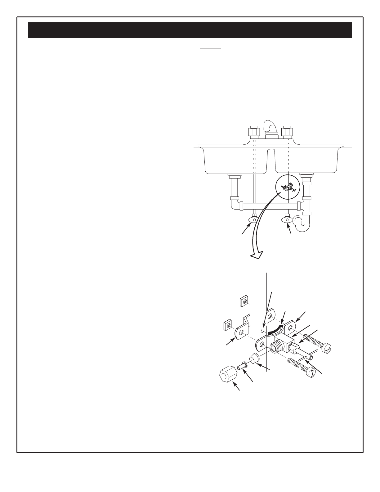
INSTALL SADDLE VALVE
(Included with your package)
This fitting will be installed on the cold water pipe. The
fitting must provide a leak-tight connection to the
Reverse Osmosis 1/4" tubing.
Complete the following steps to install the saddle valve
assembly.
1. Review Fig. 5 and familiarize yourself with all parts of
the saddle valve. This valve will self-tap a hole in copper tubing or plastic pipe.
IMPORTANT: Before starting, close the hot and cold
water shutoff valves (See Figure 5).
2. If installing on iron pipe, drill a 1/8” hole for the piercing pin.
IMPORTANT: If a battery-powered hand drill is not
available and an electric drill is used, ensure that the
drill is properly grounded.
3. Place the seal on the inside of Clamp X. See Fig. 5.
Turn the valve handle all the way out.(counter-clockwise) Be sure the piercing pin does not stick out
beyond the seal.
4. Place Clamp X and Z around the pipe. Secure in place
with two screws. Tighten both screws evenly. Do not
over tighten screws. See Fig. 5.
5. Turn the valve handle all the way in. (clockwise) This
will pierce the wall of the pipe. See Fig. 5.
Figure 5
6. Do not connect the tubing to the fitting at this time.
This will occur later in the installation.
NOTE: Once the saddle valve is installed, the nut near
the handle may need to be tightened to prevent possible leaks.
Saddle Valve Connection
(Included in package)
Clamp Z
Nut
Nut - tighten
if necessary
Insert
Ferrule
(Plastic)
Use to Connect
Tubing
Handle
Valve
Clamp X
Seal
Pre-Drill
1/8'' Hole
(Iron Pipe)
Cold Water
Shutoff Valve
Hot Water
Shutoff Valve
9
Questions? Call The Kenmore Water Line 1-800-426-9345 or visit KenmoreWater.com
Step 2 - Install RO Drain Under Sink
Figure 6
Figure 7
Figure 8
INTRODUCTION
A suitable drain point is needed for the reject water from
the Reverse Osmosis Filter. You have two options to
choose from:
• Install the Drain Adapter included with your unit
See Figures 6, 7 & 8. This is used in under the sink
installations. The drain adapter kit is installed onto
your sink drain pipe above the P-trap. See Figure 6.
• Use another existing drain in your home
This is usually used in remote location type installations. The drain tube from the Reverse Osmosis Filter
runs directly to an open drain. See Figures 9 & 10.
NOTE: Local code may dictate which type of drain
installation is used. Other than local code, either drain
installation types may be used. Consult a plumber if you
are not familiar with plumbing procedures.
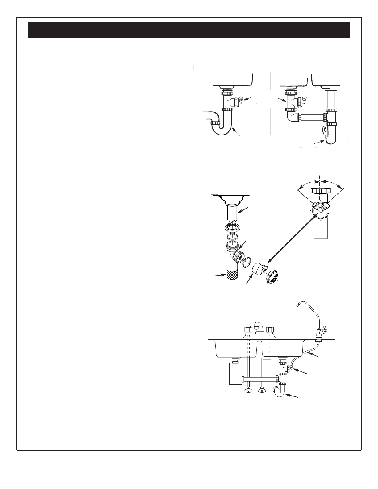
INSTALL DRAIN ADAPTER KIT
(Under sink Installation)
In an under the sink installation, you normally use the
P-trap drain adapter. A drain adapter kit is included in
your package. Review the drain adapter kit parts in
Figure 8. The drain adapter is always installed in the
sink drain pipe, above or ahead of the P- trap. See
Figures 6 & 8. Be sure to comply with your local plumbing codes. The drain adapter fits 1-1/2" sink drain pipes.
Other drain pipe fittings, purchased locally, may be
needed in addition to the adapter.
1. Slowly disassemble the sink drain pipe between the
sink P-trap and the sink tailpiece. See Figures 6 & 8.
2. Clean the sink tailpiece to assure a leak-tight fit.
3. Install drain adapter directly onto the sink tailpiece
using the ferrule and nut. Snug the nut, but do not
tighten. See Figure 7.
4. Assemble the drain tubing connector to the drain
adapter using the ferrule and nut. Snug the nut, but
do not tighten. See Figure 7.
NOTE: Locate so drain tubing from the Reverse
Osmosis faucet will make a straight run to the adapter,
without dips, loops, low spots or kinks. See Figure 8.
5. Turn the connector to about 45° (10:00 or 2:00 position). See Figure 7. Tighten the nut securely.
6. Assemble the P-trap to the drain adapter, and other
drain pipe fittings as required to complete the drain
run. See Figure 6.
NOTE: If needed, you can cut the unthreaded end of
the adapter to make it fit. Do not cut too short or the
adapter will not make a leak-tight seal with the connecting fitting.
7. Tighten all connections, but do not over tighten plastic
connections.
Drain
Adapter
P–Trap
P–Trap
Single trap
Double Trap
Under The Sink Installation
45°
45°
2:00
10:00
Sink Tailpiece
Drain Adapter
Drain Tubing
Connector
Cut, if
needed
Ferrule
Nut
Nut
Ferrule
IMPORTANT: Locate drain adapter so when the black drain tube
from the Reverse Osmosis Faucet is installed later on,
it will make a straight run to the adapter, without
dips, loops, low spots or kinks.
P-Trap
HOT
COLD
Drain Adapter
Black Drain
Tube
 Loading...