

Kenmore 625.384720 User Manual

OWNER’S
MANUAL
• ,.»■ ,
MODEL NO.
UltraFilter 300
625.384720
UltraFilter 500
625.384750
Caution:
Read and Follow
All Safety Rules and
Operating Instructions
Before First Use of
This Product.
mmm ,i
■■
I
KenmorG
Reverse Osmosis Drinking Water System
♦ Warranty
If you have questions when
installing, operating or
maintaining your reverse
osmosis system, call this
toll-free number...
1-800-426-9345
www.KenmoreWater.com
SAVE THIS MANUAL
PRINTED IN U.SA.
♦ How To Install
♦ How It Works
♦ Care Of
♦ Repair Parts
System tested and certified by NSF Internationai
to ANSI/NSF Standard 58 for the reduction of the
claims specified on the performance data sheet.
Sears, Roebuck and Co., Hoffman Estates, IL 60179 U. S. A.
Part No. 7227352 (Rev. L10/21/03)
X..

- WARRANTY -
FULL WARRANTY ON REVERSE OSMOSIS DRINKING WATER SYSTEM
(except filter cartridges and R. O. membrane)
For one year from the date of purchase, when the Reverse Osmosis Drinking Water System is installed
and maintained in accordance with our instructions, Sears will repair, free of charge, defects in materia!
and workmanship, except filter cartridges and the R. O. membrane.
TO OBTAIN WARRANTY SERVICE, SIMPLY CONTACT THE NEAREST SEARS SERVICE CENTER
THROUGHOUT THE UNITED STATES. This warranty applies only while this product is in use in the
United States.
This warranty gives you specific legal rights, and you may have other rights which vary from state to state.
Sears, Roebuck and Co., D/817 WA, Hoffman Estates, IL 60179
SEARS INSTALLATION POLICY
AH installation labor arranged by Sears shall be per
formed in a neat, workmanlike manner in accor
dance with generally accepted trade practices. Fur
ther, all installations shall comply with all local laws,
codes, regulations, and ordinances. Customer shall
also be protected during installation by insurance re
lating to Property Damage, Workman's Compensa
tion and Public Liability
- SAFETY GUIDES -
Y Read aU steps and guides carefully before instal
ling and using your reverse osmosis system. Follow
all steps exactly to correctly install. Reading this
manual will also help you to get all the benefits from
the reverse osmosis system.
Y Do not attempt to use this product to make safe
drinking water from non-polable water sources. Do
not use the system on microbiologically unsafe wa
ter, or water of unknown quality without adequate
disinfection before or after the system. This system
is certified for cyst reduction and may be used on
disinfected water that may contain filterable cysts.
Y Check with your local public works department
for plumbing and sanitation codes. You must fol
low their guides as you install the system. Follow
your local codes if they differ with guides in this
manual.
Y This system shall only be used for arsenic reduc
tion on chlorinated water supplies containing de
tectable residual free chlorine at the system inlet.
Water systems using an inline chlorinator should
provide a one minute chlorine contact time before
the RO system.
Problems, Questions? Call 1
800
SEARS INSTALLATION WARRANTY
In addition to any warranty extended to you on the
Sears merchandise involved, which warranty be
comes effective the date the merchandise is installed,
should the workmanship of any Sears arranged
installation prove faulty within one year. Sears will,
upon notice from you, cause such faults to be cor
rected at no additional cost to you.
▼ This system is acceptable for treatment of influ
ent concentrations of no more than 27 mg/L nitrate
and 3 mg/L nitrite in combination measured as N
and is certified for nitrate/nitrite reduction only for
water supplies with a pressure of 280 kPa (40 psig)
or greater.
▼ The re verse osmosis system works on water p res sures of 40 psi (minimum) to 100 psi (maximum). If
your house water pressure is over the maximum,
install a pressure reducing valve in the water supply
pipe to the reverse osmosis system.
Y Do not install the reverse osmosis system out
side, or in extreme hot or cold temperatures. Temper
ature of the water supply to the reverse osmosis sys
tem must be between 40°F and 100°F. Do not install
on hot water.
▼ Read the other limits (pH, hardness, etc.) in the
specifications and be sure your water supply con
forms. Also see "Water Supply" on page 3.
If The reverse osmosis membrane contains a pre
servative for storage and shipment. Be sure to purge
as instructed on page 9 before using product water.
2
-426-9345 Kenmore Water Line
- TABLE OF CONTENTS -
Where To Install the RO System
...............
Tools and Materials Needed ......................
Installation Steps ........................................
Cold Water Supply................................... . 5 Care of RO System
Drain Adapter
Faucet
.......................................................
RO Assembly
.........................................
...........................................
Storage Tank, Tubing Connections ...
. 4
4
. 5-9
Installation Steps - continued
Sanitizing, Pressure Test, Purging ..
How the RO System Works
..................................
. 6 Dimensions, Specifications
. 6-7 Remote Installation Locations
. 7
Repair Parts
.............................................
. 8
- WHAT YOUR REVERSE OSMOSIS SYSTEM WILL DO -
Your Reverse Osmosis (RO) Drinking Water System
is a water treatment unit. It uses household water
pressure to reverse a natural physical process called
osmosis. Water, under pressure, is forced through a
semi-permeable membrane where minerals and im
purities are filtered out. Clean drinking water goes to
the faucet or storage, while minerals and impurities
are sent to the drain with RO waste water. The miner
als and impurities are measured in water as
total dis
solved solids (IDS).
The system includes replaceable pre and postfilter
sediment-carbon cartridges. The prefilter removes
sand, silt, dirt, rust particles, other sediments, and
chlorine from the water supply before it can enter the
RO membrane. The postfilter removes any tastes
and/or odors that may remain in the water, after
passing through the RO membrane, and just before
going to the RO faucet. To prevent water waste, an
automatic shutoff valve closes when the RO faucet is
closed and the storage tank is full.
Your reverse osmosis system gives you a continuous
supply of sparkling clear, delicious water for drink
ing, cooking and other uses. Foods will look and
taste better too. Having high quality RO product wa
ter at your fingertips eliminates the need to buy
bottled water. The storage tank holds over 2 gallons
of RO product water for your needs.
....................
......................
................
.. 9
.. 10-11
.. 12-15
.. 16
.. 17
.. 18-19
- BEFORE YOU BEGIN TO INSTALL THE RO SYSTEM -
FOR OPTIMUM PERFORMANCE YOUR KENMORE REVERSE OSMOSIS SYSTEM SHOULD BE
INSTALLED ON SOFTENED WATER.
CAUTION: A refrigerator icemaker may not operate
properly when connected to a reverse osmosis sys
tem that has been installed on a water system that op
erates outside of the specified pressures listed on
page 16.
Check Your Water Supply: The cold water supply to
the RO system must be within certain quality limits.
See the specification table on page 16. If supply water
is not within limits, the RO system can not make
product water as it should and reduced RO mem
brane life will result.
Trained sales people at Sears can arrange for a free
water analysis. The analysis will tell you if other wa
ter supply treatment is needed before going to the
RO system.
CAUTION: Chlorine in the water will destroy the
RO membrane- Most cities add chlorine to the wa
ter supply to kill bacteria. The prefilter removes
chlorine up to the limits shown in the specifications
before it enters the RO membrane. It is important
to replace the prefilter cartridge at least every 6
months. See the RO care guide on page 16.
Check Parts Included: Unpack the carton and re
move the RO system. In addition to the assembled
RO and the storage tank, the system includes the
parts illustrated below, a separate length of tubing,
and this manual.
FIG. 1
TEFLON
TAPE
HANQER WASHERS
& SCREWS
TUBING
ADAPTER
WATER SUPPLY
AA BATTERIES
(MONITOR
MODEL)
RO PRODUCT
WATER FAUCET
FITTING
Problems, Questions? Call 1 -800-426-9345 Kenmore Water Une
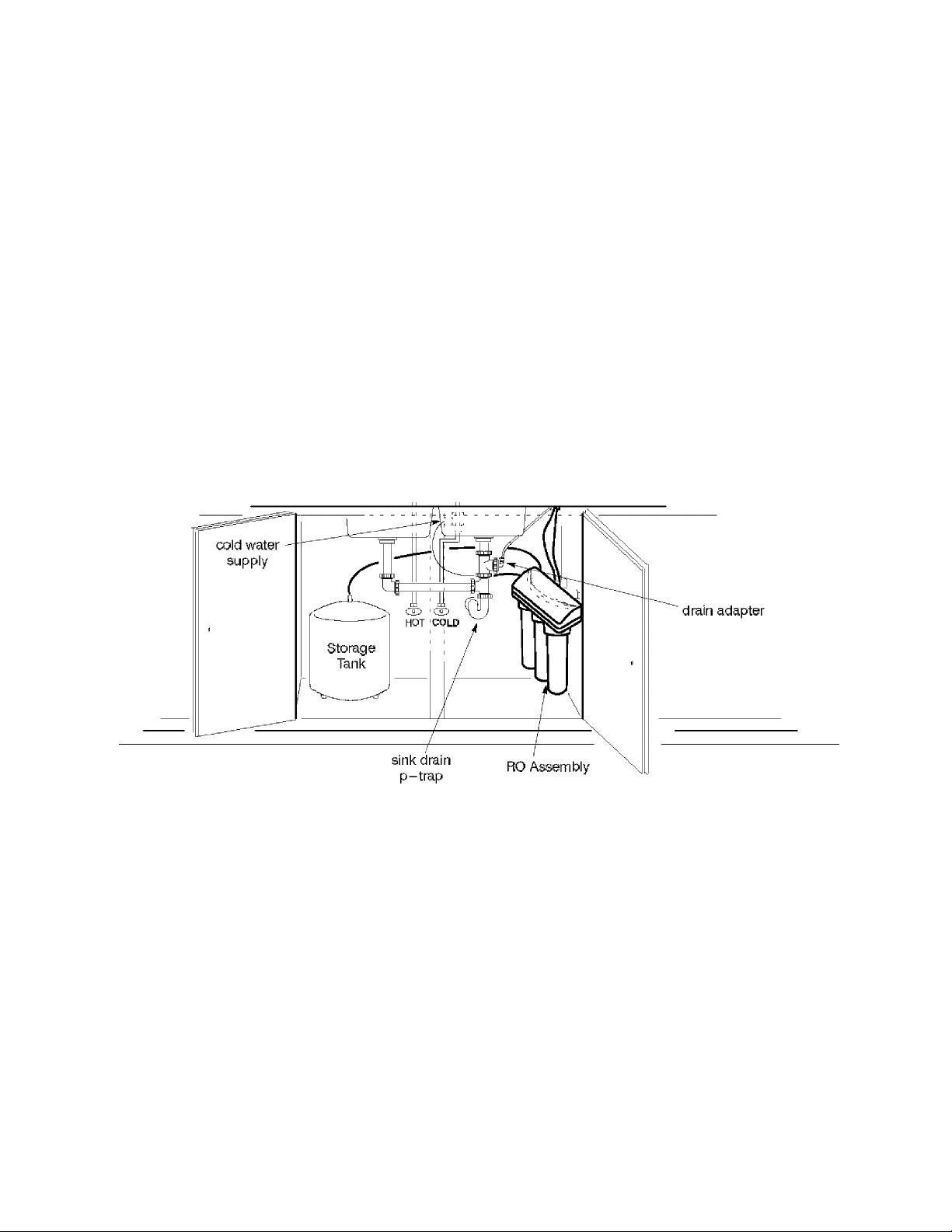
- WHERE TO INSTALL THE RO SYSTEM -
The RO assembly and storage tank is designed for
installation under the sink, usually in the kitchen or
bathroom. The RO assembly mounts on a wall sur
face, or can lay on the cabinet floor next to the storage
tank. Hanger washers and wood screws are included
for cabinet wall mounting. The RO product water
faucet installs on the sink, or on the countertop next
to the sink (pages 6 and 7).
Note: Tubing lengths allow for the removal of the
assembly from the hanger washers for servicing. If
tubing lengths are shortened for neater appear
ance, it may be necessary to keep the assembly on
the hanger washers for service.
You can also locate the RO assembly and storage tank
FiG-2
in any remote location from the faucet, observing
safety guides on page 2. You do need a nearby water
source and drain point (see page 17).
Water Supply: To provide supply water to the RO
system inlet use the included feed supply fitting or
install pipe fittings for tubing connection, as typical
ly shown on page 5.
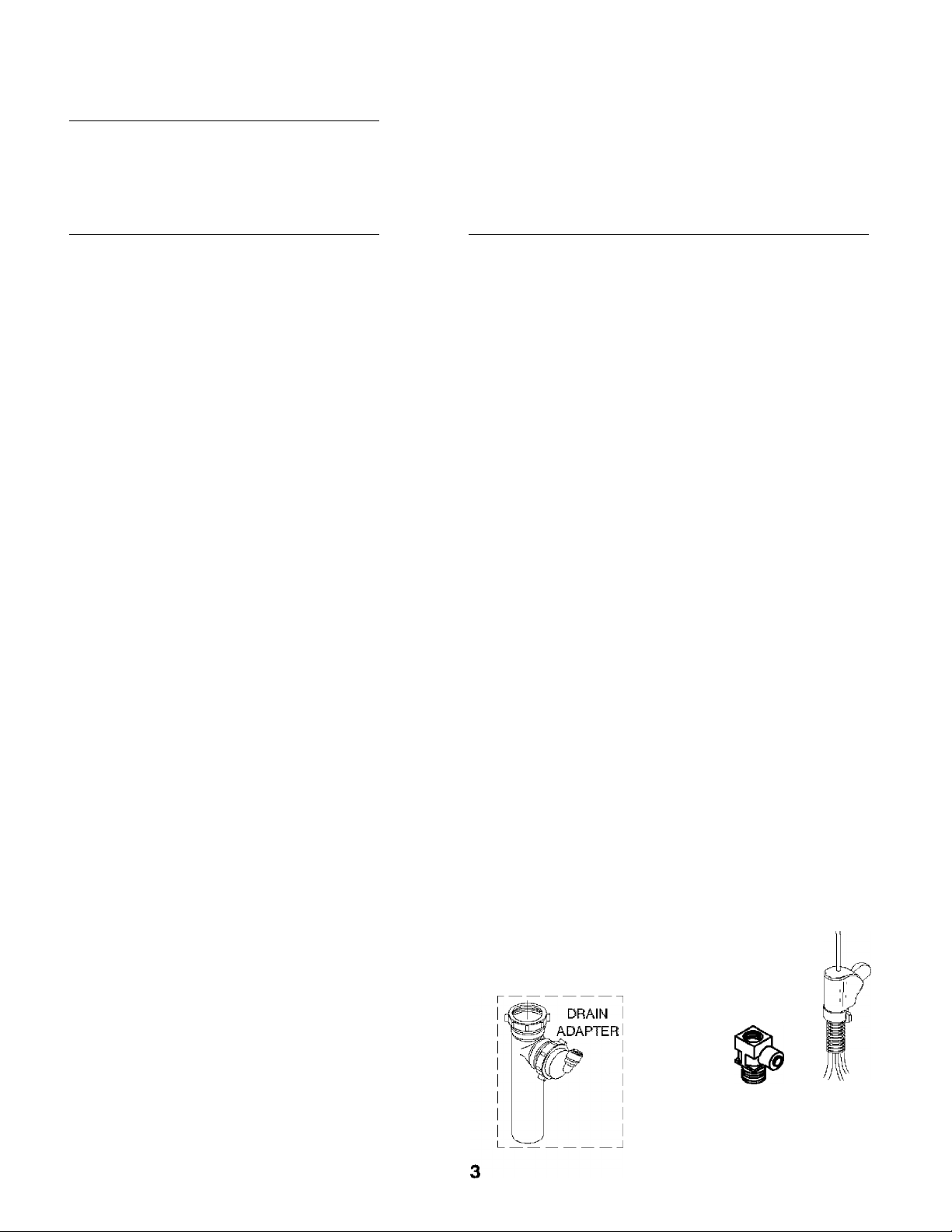
Drain Point: A suitable drain point is needed for re
ject water from the RO membrane. A floor drain,
laundry tub, standpipe, sump, etc., is preferred, as
shown in the remote locations drawing, page 17. A
sink p-trap drain adaptor is included to install where
codes permit, as an optional drain point (page 6).
RO product
water faucet
V-
— TOOLS AND MATERIALS NEEDED —
► adjustable wrench, standard pliers, and larger
adjustable jaw pliers or pipe wrench to fit sink drain
► slotted and Phillips head screwdrivers
^ plumbers putty
- 6 STEPS TO INSTALL -
STEP 1: - Install Cold Water Supply fittings - page
5
STEP 2: - Install Drain Adapter - page 6
STEP 3: - Install Faucet - pages 6 and 7
Problems, Questions? Call 1 -800-426-9345 Kenmore Water Une
^ electric drill and bits, if hole is needed for the RO
faucet, page 6 and 7
STEP 4: - Install RO Assembly - page 7
STEPS: - Install Storage Tank, Make Remaining Tub
ing Connections - page 8
STEP 6: - Sanitizing, Pressure Testing, Purging page 9
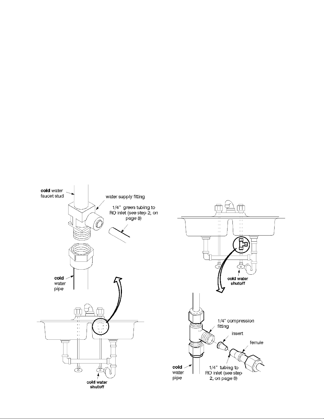
- STEP 1: INSTALL COLD WATER SUPPLY FITTING -
Check and comply with local plumbing codes as you plan, then install a cold feed (supply) water fitting. The
fitting must provide a leak-tight connection to the RO 1/4" tubing (see FIG. 8, page 8). A typical connection
using the included water supply fitting is shown in F1G.3 - A below. An optional connection, using standard
plumbing fittings (not included), is shown in B.
Note: Codes in the state of Massachusetts require installation by a licensed plumber, and do not permit the use of a saddle
valve. For installation, use plumbing code 248- CMR of the Commonwealth of Massachusetts.
A. WATER SUPPLY FITTING B. OPTIONAL PIPE FITTINGS (compression type
l.Closethe house main water shutoff valve and open shown)
faucets to drain water from the sink cold water pipe.
2, Remove nut that connects the cold water faucet to
cold water plumbing.
3, Use pipe joint compound or Teflon tape on cold water
faucet stud threads and on the male threads of the water
supply fitting that connect to the cold water pipe,
4, Thread water supply fitting onto pipe and recoimect
nut to bottom of fitting.
Note: Be sure to turn off the water supply and open
a low faucet to drain the pipe.
Complying with plumbing codes, install a fitting on
the kitchen cold water pipe to adapt 1 /4" OD tubing.
A typical connection is shown in figure 3B. If
threaded fittings are used, be sure to use pipe Joint
compound or Teflon tape on outside threads.
FIG.3
A. WATER SUPPLY CONNECTION
(using included water supply fitting)
B. WATER SUPPLY TYPICAL CONNECTION
(using compression fitting)
- parts not included -
Problems, Questions? Call 1 -800-426-9345 Kenmore Water Une
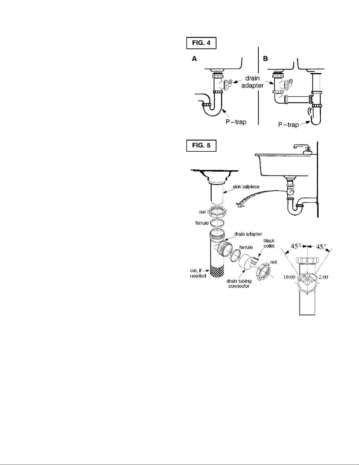
- STEP 2: INSTALL DRAIN ADAPTER -
■ Note: Running the drain tubing directly to a floor
drain, sump, standpipe, laundry tub, etc., as shown
on page 17, is preferred. However, if that is not pos
sible or practical, the included drain adapter installs
in the sink drain pipe, always above or ahead of the
p-trap (FIG. 4). Be sure to comply with your local
plumbing codes. Other drain pipe fittings, in addi
tion to the adapter, may be needed.
■ The drain adapter fits 1-1/2" sink drain pipe.
■ The adapter installs directly onto the sink tailpiece
as typically shown in FIG. 4 and 5.
■ Locate so drain tubing from the faucet (installed in
step 1, page 8) makes a straight run to the adapter,
without dips, loops, low spots or kinks.
Note: Consult a plumber if you are not familiar with
plumbing procedures.
1. Use a ferrule and nut to assemble the drain tubing
connector to the drain adapter (FIG. 5). Turn the con
nector to about 45“ from the 12:00 position, as shown
(to 10:00 or 2:00 position as needed), lighten the nut
securely.
2. Carefully disassemble the sink drain pipe and
clean the tailpiece to assure a leak-tight fit.
3. Install the drain adapter onto the sink tailpiece,
using a ferrule and nut. Snug the nut, but do not
tighten.
Note: If needed, to make fit, you can cut to shorten
the unthreaded end of the adapter. Do not cut too
short so the adapter will make a leak-tight seal with
the connecting fitting.
4. Assemble the p-trap to the drain adapter, and oth
er drain pipe fittings as required (check codes) to
complete the drain run.
5. Tighten all connections, but do not overtighten and
break plastic fittings.
- STEP 3: INSTALL FAUCET -
A. PREPARE MOUNTING HOLE
1. Select one of the following places for the faucet. Be
sure it win fit flat against the surface, and there is
space underneath for tubing (see FIG. 8, page 8).
^ Use an existing sink top hole for a spray hose or
other faucet. A 1-1/8" to 1-1/4" diameter hole is
needed.
^ Drill a new hole in the countertop next to the
sink.
^ Drill a new hole in the sink top.
CAUTION: To avoid damaging a sink beyond re
pair, consult a qualified plumber or installer for
guides to drill holes in porcelain or stainless steel.
2. If drilling is needed, make the 1-1/ 8" to 1 -1/4" di
ameter hole.
3. Place plumbers putty around the drilled hole (FIG.
6) to prevent water leakage around the base of the
faucet.
Problems, Questions? Call 1 -800-426-9345 Kenmore Water Une
 Loading...