

Page 1
OWNER’S
MANUAL
MODEL NO.
625.384600
Caution:
Read and Follow
All Safety Rules,
Installation and
Operating
Instructions
Before First Use
of This Product.
If you have questions
when installing and us
ing your drinking water
filter system, call this
toll-free number,..
1 - 800 - 426 - 9345
SAVE THIS MANUAL
KenmorG
UNDERSINK DRINKING
WATER FILTER
SYSTEM
♦ Safety Guides
♦ Installation
♦ Operation
♦ Cartridge Replacement
♦ Repair Parts
System tested and certified by NSF International to
ANSl/NSF Standard 42 and 53 for the reduction of
the claims specified on the performance data sheet.
Sears, Roebuck and Co., Hoffman Estates, IL 60179 USA
Page 2

SAFETY GUIDES / SPECIFICATIONS
Y Read all steps and guides carefully before instal
ling and using your undersink drinking water filter
system. Follow all steps exactly to correctly install.
Reading this manual will also help you to get aU the
benefits from the under sink drinking water filter
system.
Y t)o not use with water that is microbiologically
unsafe or of unknown quality without adequate
disinfection before or after the system. This system
is certified for cyst reduction and may be used on
disinfected waters that may contain filterable cysts.
Y Check with yo ur lo cal public works dep artment
for plumbing and sanitation codes. You must fol
low their guides as you install the system. Follow
your local codes if they differ with guides in this
manual. In Massachusetts, plumbing codes of
Min. - Max. Supply Water Pressure
Min. - Max. Supply Water Temperature
Inlet - Outlet
Massachusetts shall be adhered to. Consult with
your licensed plumber.
Y The undersink drinking water filter system
works on water pressures of 40 psi (minimum) to 100
psi (maximum). If your house water pressure is over
the maximum, install a pressure reducing valve in
the water supply pipe to the filter system.
Y Do not install the undersink drinking water filter
system outside, or in extreme hot or cold tempera
tures. Temperature of the water supply to the under
sink drinking water filter system must be between
40 °F and 100° F. Do not install on hot water.
Y Read the other limits (pH, hardness, etc.) in the
specifications and be sure your water supply con
forms.
40- 100 psi
40 - 100 °F
3/8” NPT, fittings and
tubing included
WARRANTY
FULL ONE YEAR WARRANTY ON UNDERSINK DRINKING WATER FILTER SYSTEM
For one year from the date of purchase, Sears will replace this Undersink Drinking Water Filter System (except
filter cartridges, which are purchased separately), free of charge, if defective in material or workmanship.
WARRANTY IS AVAILABLE BY SIMPLY RETURNING THE UNDERSINK DRINKING WATER FILTER
SYSTEM TO THE NEAREST SEARS STORE THROUGHOUT THE UNITED STATES.
This warranty gives you specific legal rights, and you may have other rights which vary from state to state.
Sears, Roebuck and Co., DEPT. 817 WA, Hoffman Estates, IL 60179
Page 3

TABLE OF CONTENTS
Parts of the System / Typical Installation Drawing / Tools and
Materials Needed .............................................................................................. 4
Drinking Water Filter System Installation ......................................................5-7
Installing Supply Fitting....................................................................... 5
Installing Faucet.....................................................................................5-6
Installing Filter Cartridge
.......................................................................
7
Using the Filtered Water System ...................................................................... 8
Filter Cartridge Life / Replacement.................................................................8-9
Repair Parts ................................................................................................ 10-11
Locate the water filter housing on the cold water supply pipe, under the kitchen and / or bathroom sink, to filter
the cold drinking water. Refer to the following drawing.
FILTERING WATER TO ONE FAUCET
kitchen sink
C® CD
HOT COLD
n
r
1
filtered water faucet
1
1 -
________________
DRINKING WATER
FILTER SYSTEM
FILTER I FILTER II
Page 4
PARTS OF THE SYSTEM
MATERIALS AND TOOLS NEEDED
• plumbers putty
y* filter system assembly including mounting brack
et and screws
y water supply fitting
y filtered water faucet for sink or countertop mount
ing
y tubing to make all needed connections
TYPICAL UNDERSINK INSTALLATION
FIG. 1
tittered water
DiSn _
faucet
• slotted and Phillips screwdrivers
• pliers and adjustable jaw wrench
• tubing cutter
• sandpaper or emery cloth
• electric drill and 3 / 4" drill bit if mounting hole is
needed for the faucet, see page 6
CAUTION; To avoid damaging the sink, consult a
qualified plumber or installer for drilling procedures
in porcelain or stainless steel.
SINK
T
HOT COLD
shutoff valve
Note: To change the fil
ter cartridge, you must
turn off the water and re
lease pressure by open
ing the faucet. A nearby
shutoff valve is conve
nient. Most sinks al
ready have shutoff
valves on the supply
pipes.
WATER
OUT
supply fitting
\
Filter II
Filter I
Note: Be sure to allow a minimum space of 1-1/2” under
the system for removing the sumps, to change the
cartridges.
Page 5

INSTALLATION STEPS
STEP 1 - COLD WATER SUPPLY FITTING
Check and comply with local plumbing codes as you plan, then install a cold feed (supply) water fitting. The
fitting must provide a leak-tight connection to the water filter 3/8" tubing. A typical connection using the in
cluded water supply fitting is shown in FIG.2 - A. An optional connection using standard plumbing fittings
(not included), is shown in B.
A. WATER SUPPLY FITTING
1. Close the house main water shutoff valve and
open faucets to drain water from the sink cold water
pipe.
2. Remove nut that connects the cold water faucet to
cold water plumbing,
3. Thread water supply fitting onto pipe and reconnect
nut to bottom of fitting.
FIG.2
A. WATER SUPPLY CONNECTION
(using included water supply fitting)
B. OPTIONAL PIPE FITTINGS
(compression type shown)
Note: Be sure to turn off the water supply and open
a low faucet to drain the pipe.
Complying with plumbing codes, install a fitting on
the cold water pipe to adapt 3 /8" OD tubing. A typi
cal connection is shown in figure 2B. If threaded fit
tings are used, be sure to use pipe joint compound or
Teflon tape on outside threads.
B. WATER SUPPLY TYPICAL CONNECTION
(using compression fitting)
- parts not included -
Page 6

INSTALLATION STEPS
STEP 2 - MAKE HOLE FOR FILTERED
WATER FAUCET
Select 1 of the following places to install the faucet. Be
sure there's room underneath so you can make the
needed connections.
- - In an existing sink spray attachment hole.
- - DriU a hole in the sink top.
- - DrUl a hole in the countertop next to the sink.
1. If drilling is needed make a 3/4" dia, (minimum)
hole for the faucet.
CAUTION: To avoid damaging the sink, consult a
qualified plumber or installer for drilling procedures
STEP 3 - ASSEMBLE AND
INSTALL FAUCET
Note: If the faucet is not assembled, slide the lever
over the cylindrical nut. Then push or turn the spout
into the faucet body.
1. Faucet, FIG. 4:
A. If not already assembled, install the rubber wash
er, spacer, flat (or lock) washer and hex nut onto the
threaded faucet stud.
in porcelain or stainless steel Special drill bits are
made for this.
2. Place plumbers putty around the drilled hole to
prevent water leaks around the faucet.
FIG. 3
plumbers
putty
FIG. 4
insert spout
remove tub
ing piece
faucet & spout
B. Apply Teflon tape to the end of the faucet stud.
Turn the tubing adapter onto the stud and hand
tighten, then wrench 1/4 turn only. BE CAREFUL
NOT TO CROSS THREAD,
3. Wet the o-ring seals on the faucet spout. Then, re
move and discard the short piece of tubing from the
faucet body and insert the spout in it's place.
4. Connect tubing to faucet as follows.
5. Lower the faucet into the sink or countertop hole.
6. On the underside of the sink or countertop insert
the large steel washer between the mounting hole
and the spacer on the faucet stud (see assembled
view). Then turn the hex nut up to the spacer and
tighten. Tighten the hex nut so the faucet can not
move, but do not overtighten and break the faucet.
rubber washer
flat (or lock)
washer
hex nut
tubing adapter
hole in sink or
countertop
TUBING PROM
DRINKING WATER
SYSTEM
Page 7

INSTALLATION STEPS
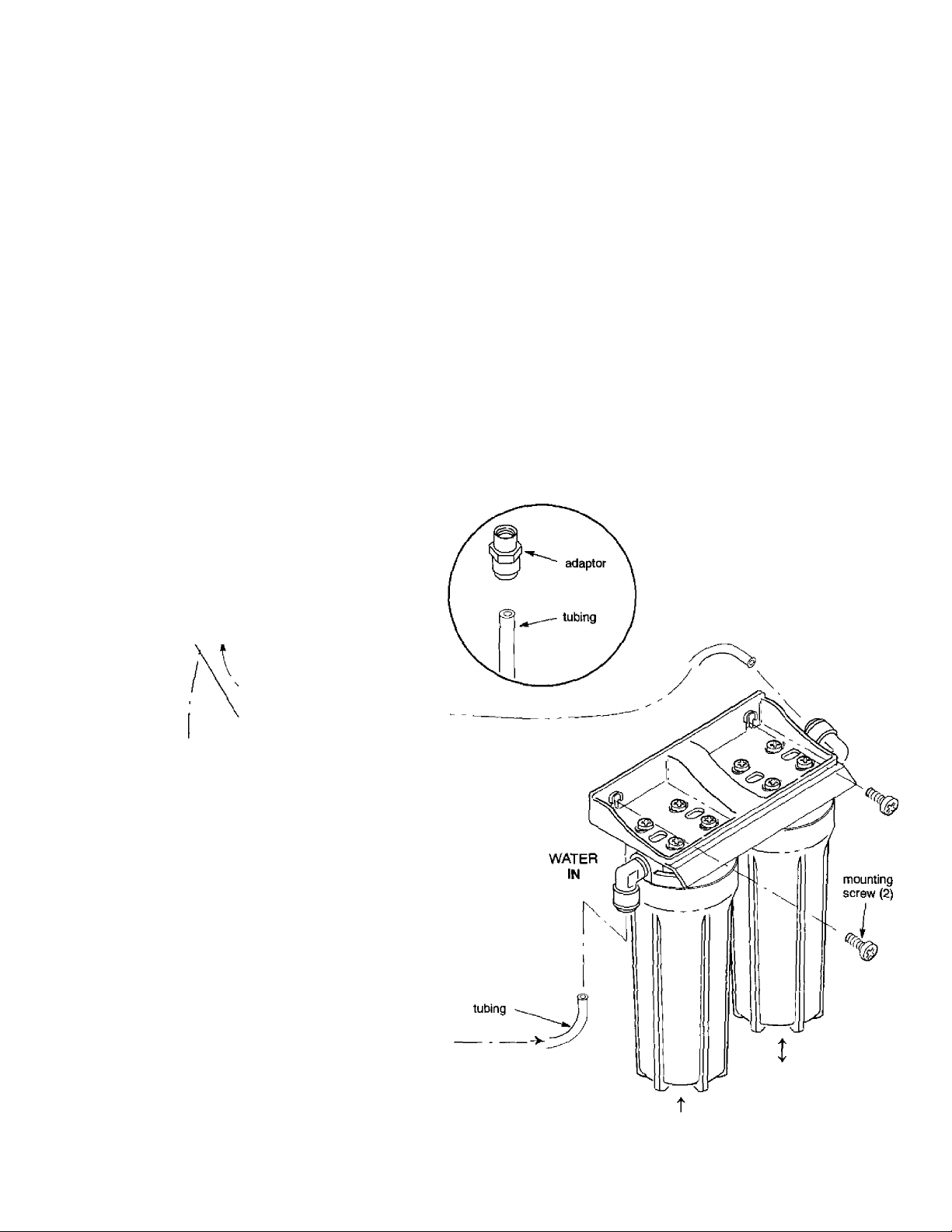
STEP 4 - MAKE TUBING CONNECTIONS
1. Allowing some slack, measure and cut a length of
3/8" tubing to connect between the supply fitting
and the filter system inlet, FIG. 1. Cut the ends of the
tubing square.
2. Insert tubing aU the way into the supply fitting and
inlet elbow fitting. Pull on the tubing to be sure that
it's held firmly in the fitting.
3. Repeat steps 1 and 2 to connect tubing between the
filter system outlet and the adaptor on the bottom of
the faucet stud, FIG. 1.
TUBING CONNECTION
(aU push-in fitting locations)
This system includes push- in fittings for quick tub
ing connection at most locations. If working with the
fittings do the following.
Connection, FIG. 5;
If tubing other than supplied with the system is
used, be sure it is of high quality, exact size and
roundness with a smooth surface.
To Disconnect Tubing: Push the collet inward and
hold with a finger while pulling the tubing out.
FIG *5
^ Tubing correctly cut and connected
cut tubing square
-------------
r—
1
1
L _
_____
1
__________________
end of tubing round and
smooth, with no cuts,
nicks or flat spots
... -1
tubing.
collet
3/4' (3/8" tubing)
collet (depress to
remove tubing)
1. Use a sharp cutter or knife to cut the end of tubing
square.
2. Inspect the end (about 1") of the tubing to be sure
there are no nicks, scratches or other rough spots. If
needed cut the tubing again.
3. Push tubing through the collet and all the way into
fitting. Full engagement is 11/16" for 1/4" tubing,
and 3/4" for 3/8" tubing.
DO NOT USE VINEGAR, OR OTHER ACID
BASED CLEANERS ON THIS SYSTEM. THEY
WILL DEGRADE SOME SYSTEM PARTS. AL
WAYS USE SOAP AND WATER.
STEF 5 - FILTER CARTRIDGE INSTALLATION
Turn to page 9 and follow all steps under "Filter Cartridge Replacement".
CAUTION
Page 8

USING THE SYSTEM
The sink or countertop faucet vends the filtered wa
ter when opened. It has a hand operated, spring
loaded closed lever to prevent waste. You can also
keep the faucet open by pushing upward on the lever
and locking it against the faucet spout.
FILTER CARTRIDGE / USEFUL LIFE / REPLACEMENT
FILTER CARTRIDGE LIFE
Several variables determine how long a cartridge
win last. These include:
1. how much water you use
2. how much sediment, taste and/ or odor, or other
unwanted substance, is in the water
Use the following information as a guide. However,
no matter which type of cartridge you are using, you
will know it is time to replace it when you first no
tice the return of the unwanted substance in your
water.
Kenmore system model 625.384600 with replace
ment elements 42-34370 and 42-34377 has been
tested and certified by NSF International for the re
duction of protozoan cysts, lead and chlorine. The
rated capacity for this system is 1000 gallons.
Other filter cartridges are available from Sears to re
move sediments, tastes and odors, and chemical con
taminants. Following is a list of filter cartridges
available.
Taste and Odor Cartridges: Many bad tastes and/or
odors are removed from water by an activated car
bon cartridge. It is most often used to remove chlo
rine taste and smeU, usually to a single faucet such as
the kitchen cold.
Note: Small amounts of hydrogen sulfide {noticeable
as "rotten egg" odor) may be reduced by taste and
odor filters for a short time, quickly exhausting the
carbon media. Consult your Sears store for proper
continuous treatment.
Sears Item No. 42-34362: for sediment removal,
Sears Item No. 42- 34365: for 99% chlorine reduction,
plus chemical contaminants
Sediment Filter Cartridge, Sears Item No. 42-34360
(25 micron): Sediment cartridges remove sand, sût,
clay, dirt, and other sediments from water. The 25
micron cartridge filters larger sediments from water,
and allows higher flows at less pressure drop.
Page 9

FILTER CARTRIDGE REPLACEMENT
CAUTION: Never remove sumps with water pres
sure in the filter system,
1. Close the water supply shut-off valve (FIG. 1,
page 4) to the filter. Open the filtered water faucet
to relieve pressure in the system.
FIG. 6
o-rtng
seal
cartridge
TURN
SUMP
CLOCKWISE
TO REMOVE
Filter I
2. Turn the sump off of the filter head, to the left or
clockwise. Be careful, the sump is full of water. Do
not lose the large o-ring seal.
Note: A special wrench is available from Sears for re
moving the sump. See the parts list on page 11.
bracket
TURN
SUMP
COUNTER
Filter II
CLOCKWISE
TO TIGHTEN
3. Be sure the inside of the sump is clean. Use hot,
soapy water and rinse thoroughly.
4. Remove the wrapper from the new filter cartridge
and insert the filter cartridge in the sump. Some car
tridges fit either way, while others fit only one way.
Observe markings on the cartridge, or on the wrap
per.
Note: If you are instalUng two different types of filter
cartridges, be sure to install in filters I and II as the
guidehne on page 3 shows.
5. Lightly lubricate the o-ring seal in the sump with
silicone grease or Vaseline. Be sure it is fully seated
in its groove.
6. Hold the sump up to the filter head aligning the
center hole in the cartridge with the protrusion on the
bottom of the head.
Note: If the sump will not tighten up to the head you
may have the cartridge in upside down. Take the car
tridge out and check for correct orientation.
7. Being careful not to cross-thread, turn (counter
clockwise) the sump onto the filter head and tighten
securely.
8. Repeat steps 2 through 7 at the other filter.
9. Open the filtered water faucet. Then, slowly open
the water supply valve and allow the filter housing
tofiU.
10. Close the filtered water faucet. Check for leaks be
tween the sump and the head.
Note: If leaking, turn off the water supply and open
the filtered water faucet to depressurize the filter.
Then disassemble the filter and check the o-ring for
cuts, flat spots, etc., and sealing surfaces for foreign
material. Clean the o-ring and lubricate with silicone
grease or Vaseline. Carefully press into the groove in
the sump.
11. Taste and Odor Cartridges: A taste and odor car
tridge contains activated carbon, a black powder.
When new, open the filtered water faucet and allow
fine, harmless carbon particles to purge from the car
tridge, Close the faucet when you no longer see the
"fines" in the filtered water, or approximately 10
minutes.
Page 10

REPAIR PARTS
Kenmore Undersink Drinking Water Filter System, Model No. 625.384600
Page 11

REPAIR PARTS LIST
KEY
NO.
1
2
3 9006053
4
5
6
7 42-34385 0-ring, 3-3/8” I.D. x 3-5/8" O.D. (2 req.)
8
9
10 7207920
11 7228536 Tee, Feed Adaptor
12
♦
❖
PART
NUMBER
7160453
7182502 Mounting Bracket
7207881
7156535 Head {2 req.)
7161255 Nipple, 3/8” NPT X 1 - 1/2”
7156577 Sump (2 req.)
7168435 Tubing, 3/8” X 72"
7228510 Faucet Assembly
7228528
42-34360 Sediment Cartridge, 25 micron
42-34362
42-34370 Taste & Odor Cartridge, 95% chlorine reduction
42-34372
42-34365
42-34377
42-34334
Screw, #10 - 14 X 3/4” (8 req.)
Screw, #10 - 14 X 1-1/4" (2 req.)
Elbow, 3/8” NPT X 3/8" Tube (2 req.)
Faucet Adaptor
Owners Manual
Sediment Cartridge, 5 micron
Taste & Odor Cartridge, 99% chlorine reduction
Taste & Odor / Chemical Contaminant Cartridge
Taste & Odor / Lead Cartridge / Cyst
Sump Removal Wrench
DESCRIPTION
♦ not illustrated
•f* available options from Sears at time of this printing, not illustrated, and not included
with Water Filter System
11
Page 12

KenmorG
UNDERSINK DRINKING
OWNERS
MANUAL
MODEL NO.
625.384600
The model number of
your drinking water filter
system is found on the
rating decai, on the
mounting bracket.
When requesting service
or ordering parts, always
provide the following in
formation;
♦ Product Type
♦ Model Number
♦ Part Number
♦ Part Description
WATER FILTER
SYSTEM
For the repair or replacement parts you need
Call 7 am - 7 pm, 7 days a week
1 - 800 - 366 - PART
(1 - 800 - 366 - 7278)
For in-home major brand repair service
Call 24 hours a day, 7 days a week
1 - 800 - 4 - REPAIR
(1 - 800 - 473 - 7247)
For the location of a
Sears Repair Service Center in your area
Call 24 hours a day, 7 days a week
1 - 800 - 488 - 1222
For information on purchasing a Sears
Maintenance Agreement, or to inquire
about an existing Agreement
Call 9 am - 5 pm, Monday - Saturday
1 - 800 - 827 - 6655
Sears, Roebuck and Co., Hoffman Estates, IL 60179 U.S.A.
____________
7228528 (09/00)
 Loading...