

Kenmore 625.383760 User Manual
Sears, Roebuck and Co., 3333 Beverly Road, Hoffman Estates, IL 60179 USA
PRINTED IN U.S.A. Part No. 7282603 (Rev. E 12/8/06)
• Warranty
• Installation
• Start Up / Setting Timer
• How It Works
• Care Of
• Specifications
• Repair Parts
Water Softeners
With High Performance Valve
www.KenmoreWater.com
Repair or Parts ? Call toll free 1-800-366-7278
See back cover for other Sears service numbers.
Caution:
Read and follow all safety rules and operating
instructions before first use of this product.
MODEL NOS.
IntelliSoft 370 Series 625.383760
IntelliSoft 370 Series 625.393760
OWNER'S MANUAL
SAVE THIS MANUAL
Use the plastic bag and tie provided, to hang manuals nearby
the softener for future reference.
Questions ?
Visit www.KenmoreWater.com
or call toll free 1-800-426-9345 (M - F, 7AM - 8 PM CST)
Systems Tested and Certified by NSF International against
NSF/ANSI Standard 44 for softener performance.

2
Questions? Call The Kenmore Water Line 1-800-426-9345
WARRANTY ON WATER SOFTENER
ONE YEAR LIMITED WARRANTY ON WATER SOFTENER
When installed, operated and maintained according to all instructions supplied with the product, if this
Kenmore appliance fails due to a defect in material and workmanship within one year from the date of purchase, call 1-800-4-MY-HOME
®
to arrange for free repair.
THREE YEAR LIMITED WARRANTY ON ELECTRONIC PARTS
When installed, operated and maintained according to all instructions supplied with the product, if any of the
following electronic parts fail due to a defect in material or workmanship, call 1-800-4-MY-HOME
®
to arrange
for free part replacement: Brine Tank Light, Electronic Board, Sensor Housing, Wiring Harness, Transformer,
Micro Switch, Drive Motor, Power Cable. After the first year you must pay an initial trip charge.
TEN YEAR LIMITED WARRANTY AGAINST LEAKS
When installed, operated and maintained according to all instructions supplied with the product, if the water
softener tank or salt storage drum develops a leak within ten years from the date of purchase, call 1-800-4MY-HOME
®
to arrange for free tank or drum replacement. After the first year you must pay an initial trip
charge.
All warranty coverage does not include water softener resin, which is an expendable item.
If this water softener is ever used for other than private family purposes, all warranty coverage applies for
only 90 days from the date of purchase.
This warranty covers only defects in material and workmanship. Sears will NOT pay for:
1. A service technician to instruct the user in correct product installation, operation or maintenance.
2. A service technician to clean or maintain this product.
3. Damage to or failure of this product if it is not installed, operated or maintained according to the all instruc-
tions supplied with the product.
4. Damage to or failure of this product resulting from accident, abuse, misuse or use for other than its intend-
ed purpose.
5. Damage to or failure of this product caused by the use of detergents, cleaners, chemicals or utensils other
than those recommended in all instructions supplied with the product.
6. Damage to or failure of parts or systems resulting from unauthorized modifications made to this product.
Disclaimer of implied warranties; limitation of remedies
Customer’s sole and exclusive remedy under this limited warranty shall be product repair as provided herein.
Implied warranties, including warranties of merchantability or fitness for a particular purpose, are limited to
one year or the shortest period allowed by law. Sears shall not be liable for incidental or consequential damages. Some states and provinces do not allow the exclusion or limitation of incidental or consequential damages, or limitation on the duration of implied warranties of merchantability or fitness, so these exclusions or
limitations may not apply to you.
This warranty applies only while this appliance is used in the United States or Canada.
This warranty gives you specific legal rights, and you may also have other rights which vary from state to
state.
Sears, Roebuck and Co., Hoffman Estates, IL 60179
Sears Canada Inc., Toronto, Ontario, Canada M5B 2B8
3
TABLE OF CONTENTS
Safety Guides ................................................................................................................................................. 4
Unpack and Check Shipment ........................................................................................................................ 5
Plan Your Installation: Tools Needed, Materials Needed ........................................................................... 6-10
Install Inlet/Outlet Adapters or Bypass Valves, Three Way Valves ...........................................................11-12
Install Softener and Connect Pipes................................................................................................................13
Connect Valve and Salt Tank Drains..............................................................................................................14
Leak Test ........................................................................................................................................................15
Electrical Requirements .................................................................................................................................16
Install Covers and Restart Water Heater .......................................................................................................17
Program the Timer ....................................................................................................................................17-18
Sanitize the Water Softener ...........................................................................................................................19
Add Salt to Storage Tank................................................................................................................................20
Install Check List ............................................................................................................................................21
Faceplate Timer Features .........................................................................................................................22-25
How Your Water Softener Works ..............................................................................................................26-28
Care of Your Water Softener.....................................................................................................................29-32
Specifications ............................................................................................................................................33-34
Service Tech Information...........................................................................................................................35-41
Exploded Views and Parts Lists................................................................................................................42-47
Sears Tech Support .........................................................................................................................Back Cover
Questions? Call The Kenmore Water Line 1-800-426-9345
FACTS AND FIGURES TO KEEP
Fill in the blanks below and keep this book in a safe place
so you always have these facts.
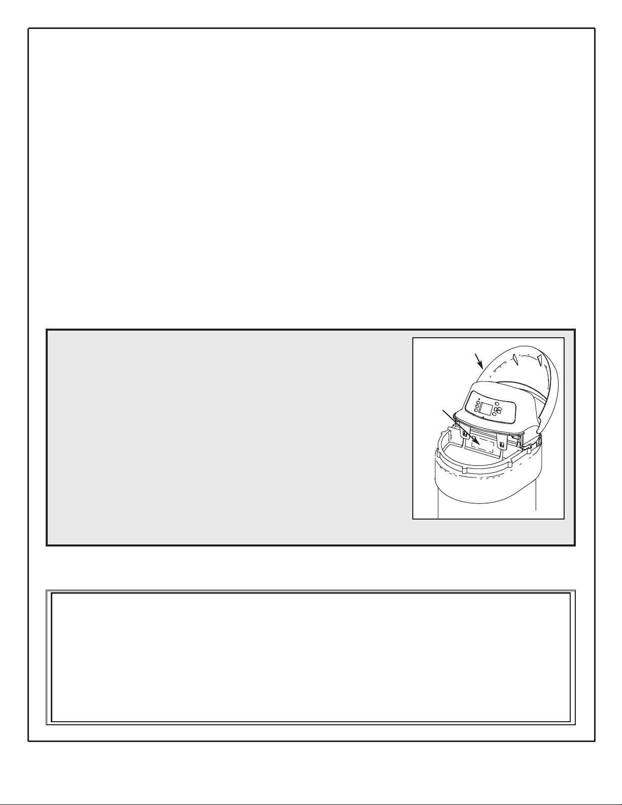
Water Softener Model No.*____________________________________
Serial Number ______________________________________________
Date Installed_______________________________________________
Water Hardness _____________________________ Grains Per Gallon
Iron Content _________________________________ Parts Per Million
pH______________________ Taste and/or Odor ________________
Water Pressure ___________________________ Pounds/Square Inch
Water Flow Rate ___________________________ Gallons Per Minute
* The model number is on the rating decal, located on the rim, under the salt hole cover.
Rating
Decal
Salt Hole Cover
Questions?
Call the Kenmore Water Line at 1-800-426-9345
or visit KenmoreWater.com
For repair or replacement parts, call toll-free 1-800-366-7278
See back cover for other Sears service numbers.

4
Y Read all steps, guides and rules carefully before installing and using your new water softener.
Follow all steps exactly to correctly install. Failure to follow them could cause personal injury
or property damage. Reading this book will also help you to get all of the benefits from your
water softener.
Y Your Kenmore Water Softener will remove hardness minerals from water. This is measured in
grains per gallon (gpg). It will also remove some clear water iron*. This is measured in parts
per million(ppm). See the specifications page for the maximum limits of hardness and iron
removal.
Y A water softener will not improve other water problems such as acidity, tastes and odors, or
iron other than clear water iron. lt will not purify contaminated water, or make unsafe water
safe to drink.
Y Check with your local public works department for plumbing, electric and sanitation codes.
You must follow their guides as you install your softener. Use only LEAD FREE SOLDER
AND FLUX, as required by federal and state codes, when installing soldered copper plumbing.
Y Protect the softener and piping from freezing. Damage from freezing voids the softener war-
ranty. See how to protect from freezing on page 31.
CAUTION: Please read and comply with the following guides to prevent damage to the softener or other property, personal injury, or possible fatal shock.
Y This softener works on 24 volts only. Be sure to use only the transformer included.
Plug it into a nominal 120V, 60 cycle household outlet that is grounded and properly
protected by an overcurrent device such as a circuite breaker or fuse. If transformer is
replaced, use only the authorized service Class II, 24 volt, 10 VA transformer.
Y Unplug the transformer right away if the power cable should become damaged or frayed.
Make repairs, or replace the transformer, before plugging back into the power outlet.
Y Always unplug the softener from electrical power before removing outer valve covers.
Y This system is not intended to be used for treating water that is microbiologically unsafe or of
unknown quality without adequate disinfection before or after the system.
* The capacity to reduce clear water iron is substantiated by WQA test data.
European Directive 2002/96/EC requires all electrical and electronic equipment to
be disposed of according to Waste Electrical and Electronic Equipment (WEEE)
requirements. This directive or similar laws are in place nationally and can vary
from region to region. Please refer to your state and local laws for proper disposal
of this equipment.
Safety Guides
5
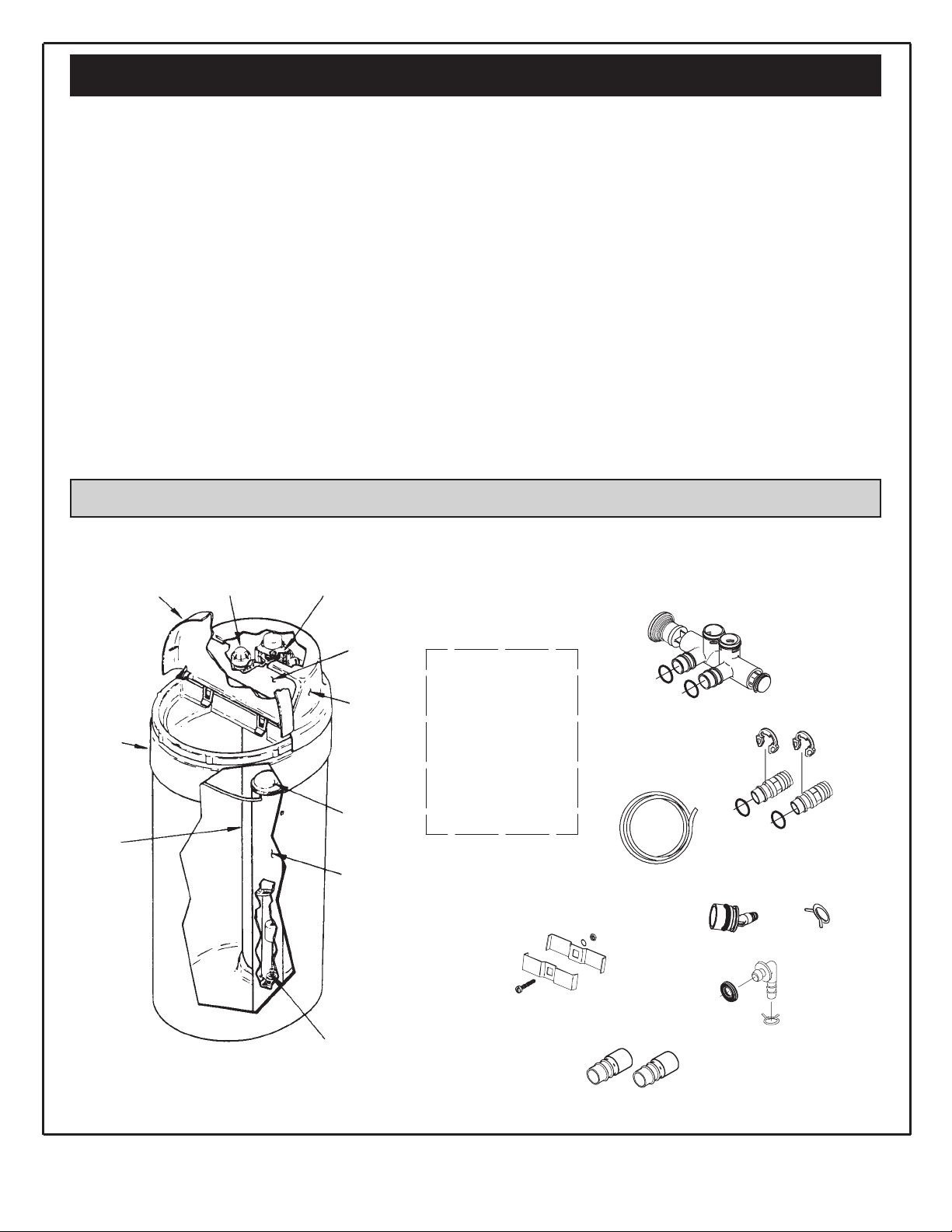
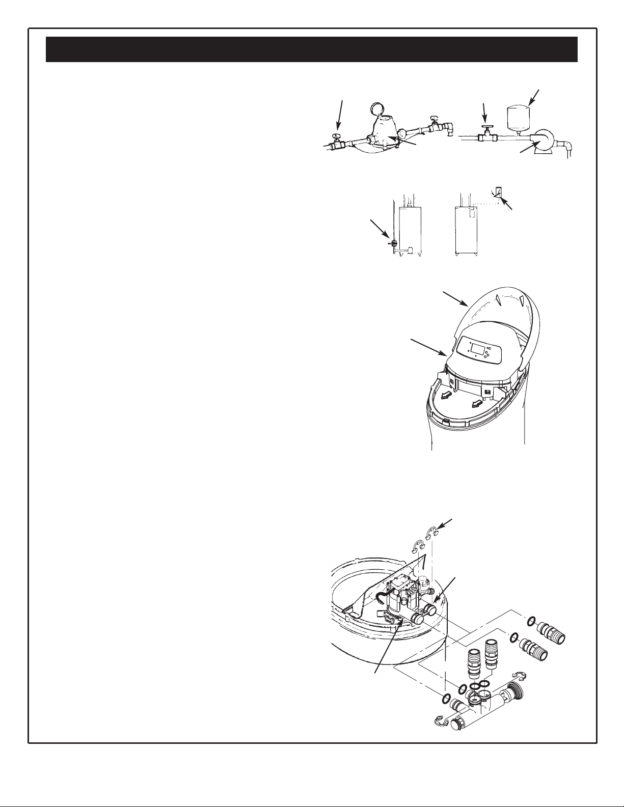
Unpack and Check Your Carton
FIG. 1
Questions? Call The Kenmore Water Line 1-800-426-9345
Packing List
INSPECT SHIPMENT
Your water softener is shipped complete in one carton.
Use care when handling the softener. DO NOT turn
upside down. DO NOT drop, or set on sharp objects that
could make a hole in the bottom. The water softener is
heavy, do not try to lift it or move more than is necessary.
Remove all items from your shipping carton.
Check all items against the packing list below. Note any
items lost or damaged in shipment.
Note any damage to the shipping carton. Refer to the
exploded view and parts list in the back of the manual for
the part names and numbers of missing or damaged
items.
Contact the store where purchased if problems exist.
PARTS DESCRIPTIONS
Nozzle
Assembly
Valve
Assembly
Face
Plate
Cover
(Main)
Brinewell
Cover
Brinewell
Brine Valve
Additional Installation Fittings avaiable from
Sears (see parts listing in back of manual)
Resin
Tank
Salt Hole
Cover
(Open)
Salt
Storage
Tank
Ground Clamp Kit
1-1/4” Copper Tubes
Drain Elbow
(installed on unit)
Tube Clamp
Tube Clamp
Clips (2)
Drain Tubing
Tube Adaptor
Grommet
O-Ring Seals (2)
SMALL PARTS
Bypass Valve
Installation
Adaptors (2)
owner’s manual
6
Plan Your Installation
PLAN YOUR INSTALLATION
It is recomended to read through the entire manual before
beginning your installation. Follow all steps exactly. Reading this
manual will also help you get all the benefits from your system.
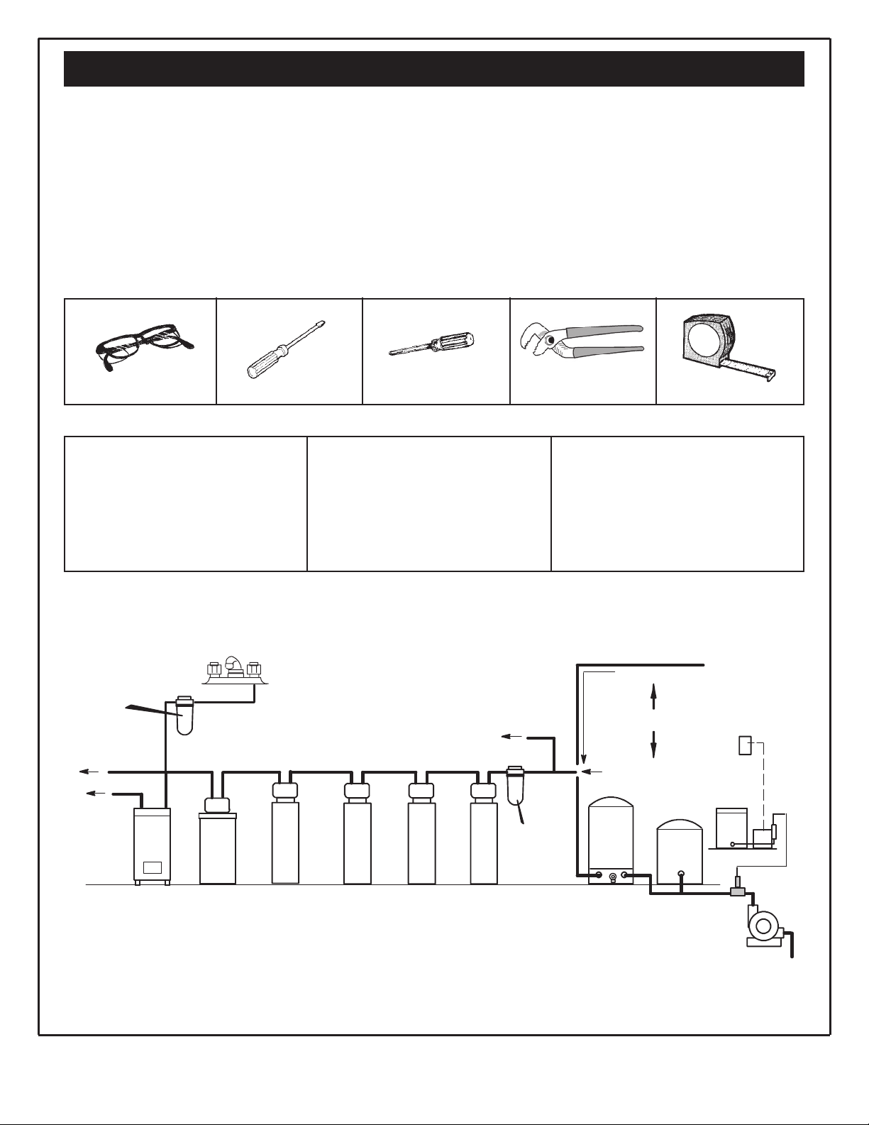
TOOLS NEEDED:
• Safety glasses
• Flathead screw driver
• Phillips screw driver
• Adjustable slip joint pliers
• Tape measure or ruler
Safety Glasses Flathead Screwdriver Phillips Screwdriver Adjustable Slip Joint Pliers Tape Measure or Ruler
SOLDERED COPPER
• Tubing Cutter
• Propane Torch
• Solid Core LEADFREE Solder
• Paste Flux
• Emery Cloth
or Sandpaper
THREADED PIPE
• Hacksaw or Pipe Cutter
• Pipe Wrenches
• Pipe Threading Tool
• Pipe Joint Compound approved
for use on potable water
CPVC OR PVC PLASTIC
• Hacksaw
• Adjustable Wrench
• Primer and Solvent Cement
approved for use on potable water-
ADDITIONAL TOOLS NEEDED FOR THE FOLLOWING INSTALLATIONS:
Questions? Call The Kenmore Water Line 1-800-426-9345
FIG. 2
THE PROPER ORDER TO INSTALL WATER TREATING EQUIPMENT
(Shows sequence of equipment only. Seldom, if ever, would all items be needed.)
Sediment or Taste &
Odor Cartridge Filter
Cold, soft water
Hot, soft water
Water
Heater
*Taste &
Odor Filter
Water
Softener
Iron
Filter
Neutralizer Clarifying
Filter
Sediment
Cartridge Filter
(Optional
Location)
Blending
Tank
Pressure or
Captive Air
Tank
Solution
Dispensing
System
Well Water
Hard Water to
Outside Faucets
City Water Supply
Well Water Supply
OR
Kitchen or Bathroom
Cold Faucet
• Always put an Iron Filter BEFORE the water softener.
• Always put a Neutralizer BEFORE an Iron Filter, etc., as shown.
* A Taste & Odor Filter may be used before or after the water
softener.
7
Plan Your Installation
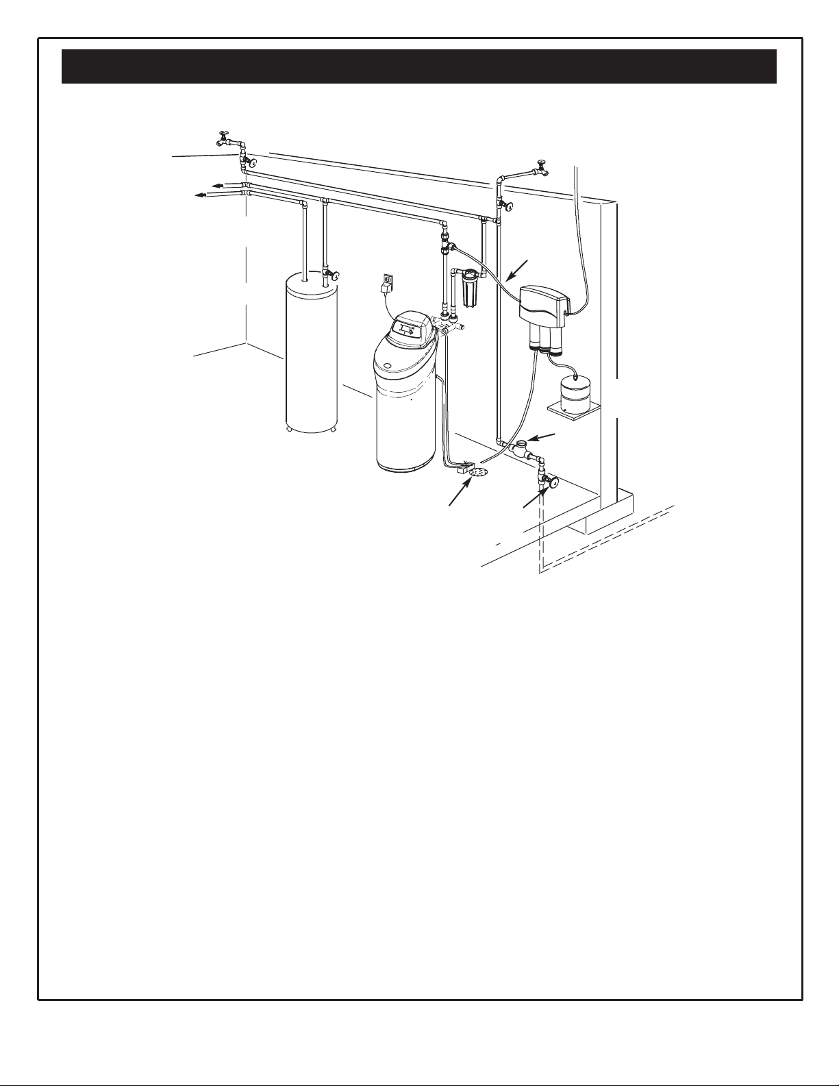
Typical Installation
1. Place as close as possible but always after, the
pressure tank (well water) or water meter (city
water). See Fig. 3.
2. Place as close as possible to a water drain such as
a floor drain, laundry tub, sump or standpipe. See
Fig. 3.
3. Connect to the house main water pipe BEFORE
THE WATER HEATER. See Fig. 3. Temperature of
water going through the softener must not be
more than 120°F (49°C). Hot water will damage
inner softener parts. To reduce the risk of hot water
backup, piping between the softener and water
heater should be as long of a run as possible.
4. Keep outside faucets on hard water to save soft
water and salt. See Fig. 3.
5. Do not install in a place where the softener could
freeze. Damage caused by freezing voids the warranty by Sears, Roebuck and Co.
6. Put the softener in a place where water damage is
least likely to occur if it develops a leak. Sears or
the manufacturer will not repair or pay for water
damage.
7. A grounded, 120V electrical outlet is needed within
10 feet of the softener. See Fig. 3. This is to plug in
the transformer. The softener has a 10 foot power
cable. Be sure the outlet and transformer are in
an inside place, to protect from wet weather. Use
a continuously “live” outlet, which cannot be accidentally switched off.
8. When installing in an outside location, you must take
the steps necessary to assure the softener, installation plumbing, and wiring, are protected from the
elements, contamination, vandalism, etc.
9. Keep the softener out of direct sunlight. The sun’s
heat can melt plastic parts.
WHERE TO INSTALL THE WATER SOFTENER
Review the following points before you choose a place to put your softener.
Questions? Call The Kenmore Water Line 1-800-426-9345
FIG. 3
Outside faucet
(Hard Water)
Outside Faucet
(Hard Water)
To Faucet
Soft, Cold Water
Soft, Hot
Water
Hard
Water to
House
R.O.
Storage
Tank
Reverse
Osmosis
system
Water
Softener
Water
Heater
Soft water
to Reverse
Osmosis
System
Shut-off
Valve
Reverse
Osmosis
Drain
Hard Water Line
Main
Shutoff
Valve
Air
Gap
Water
Meter
Floor
Drain
8
Plan Your Installation
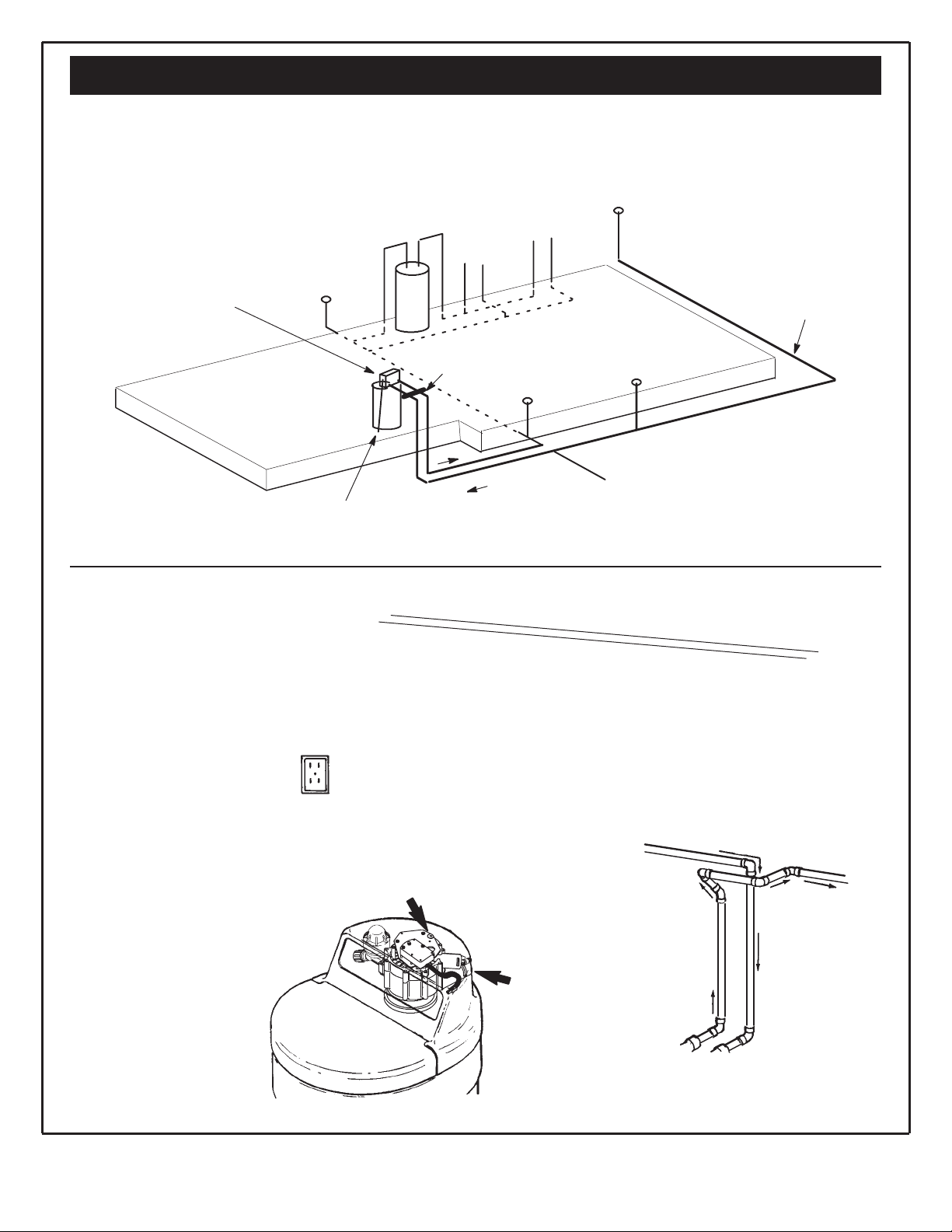
Suggested Slab Foundation Installation
Plug the softener transformer
into an inside, 120 volt 60Hz
electrical outlet. If an outside
outlet is used, be sure it has
approved weather protection.
Run drain tubing to laundry tub or
p-trap inside home, if possible.
Otherwise, run to a dry well.
WATERSOFTENER
(install in garage, car port,
or other sheltered area)
bathroom
kitchen
For outside hard
water, trench underground as needed.
outside
-soft
outside
-soft
outside
- hard
outside
- hard
water heater
water in
bypass
valve
Questions? Call The Kenmore Water Line 1-800-426-9345
Your House Main Water Pipe
Left
Right
120V - 60Hz
Electrical
Outlet
Valve Outlet Side
Valve Inlet
Inlet
Outlet
To Water Softener
Raw Water
Soft Water
Main Water Pipe
CROSS-OVER
* In what direction does the water flow?
Be sure to plan “IN” and “OUT” piping so water
flow is to the softener valve inlet. Plan a
crossover if flow is from left to right.
DRAW IN YOUR PIPES
AND FITTINGS
Draw the plans for your “IN” and “OUT”
piping here. Include all pipe, fittings and
accessories you will use.
Make a list of all materials you will need
and buy them before you begin to install
the water softener.
FIG. 5
FIG. 4
9
PIPE, FITTINGS, OTHER MATERIALS NEEDED
You must first decide how to run “in” and “out” pipes to
the softener. Look at your house main water pipe at the
point you will connect the softener. Is the pipe soldered
copper, glued plastic, or threaded galvanized or brass?
What is the pipe size? What kind of pipe and fittings is it
easiest for you to work with, and what tools do you have?
Now look at the common plans for “in” and “out” piping
on soldered copper. See Fig. 6. Use it as a guide to plan
what materials you will need. Get all the materials you
will need before you start.
Use Fig. 5 to make a plan drawing for your specific
installation. “In” and “out” fittings included with the softener are 1” NPT threaded adaptors. You should maintain
the same, or larger, pipe size as the water supply pipe,
up to the softener inlet and outlet. Use copper, brass,
galvanized or PVC plastic pipe and fittings for the “in”
and “out” pipes. Be sure to check local codes.
Note: If converting from galvanized to copper pipe
use approved dielectric insulating connectors.
ALWAYS install the bypass valve (that is included with
the unit) or a three valve bypass. See Fig. 9 to13.
Bypass valves let you turn off water to the softener if
needed for repairs, but still have water in the house
pipes.
Drain tubing (3/8” inside diameter), is needed for the
valve and salt tank drains. See Fig. 16. If a rigid valve
drain is needed to comply with plumbing codes, you can
buy the parts needed (see Fig. 16) to change the softener to a 1/2 inch minimum copper tubing drain.
Questions? Call The Kenmore Water Line 1-800-426-9345
Plan Your Installation
FIG. 6
IN
IN
OUT
OUT
1” NPT sweat
adaptor (2)*
Bypass
Valve
1” NPT
adaptor
2 of each
included
To connect to 1-1/4”
copper household
plumbing
To connect to 1-1/4”
copper household
plumbing
2 of each
included
clip
clip
SOLDERED
*NOTE:
For plumbing connection, buy 2 sweat adaptors and plumb
directly to the inlet - outlet adaptors. Threads on the inlet - outlet
adaptors are 1” NPT.
CAUTION:
DO ALL SOLDERING BEFORE CONNECTING SWEAT ADAPTORS TO INLET-OUTLET ADAPTORS OR BYPASS VALVE.
Valve
Inlet
1” NPT
adaptor
1” NPT sweat
adaptor (2)*
Valve
Inlet
Use teflon tape,
pipe joint compound
or both.
Use teflon tape,
pipe joint compound
or both.
10
Read Before Beginning Installation
BEFORE INSTALLING CHECKS & TESTS
Your water supply needs to be checked for chemical
analysis, water pressure and water flow rate. To accomplish this, complete the following steps:
Check Water’s Chemical Analysis: Sears sells a complete line of water treating equipment to correct various
water problems. To be sure you have the proper type
and size equipment, You must have your water tested.
Your Sears store can give you a water test results for
hardness, iron and acidity, and tell you what equipment
you need. Simply take at least a 4 oz. sample of your
water to Sears, and they will test it while you wait. If you
need help to get your water tested, or if you have other
questions about your water, ask at your Sears store.
NOTE: Add these readings to the Facts and Figure
table on page 3.
Check Your Water Pressure: For your softener to work
right, a water pressure of no lower than 20 pounds per
square inch (psi) is needed in the house water pipes.
The highest pressure allowed in the water pipes is 125
psi. If pressure is over 125 psi, buy and install a pressure reducing valve in the water inlet pipe to the softener.
NOTE: If water pressure during the day is 100 psi or
more, pressure during the night may go over 125 psi.
Adding a pressure reducing valve may reduce the
flow.
NOTE: Add these readings to the Facts and Figure
table on page 3.
If you have a well water system, look at the pressure
gauge to find the water pressure. Call your local water
department if you have city water. They will tell you what
the water pressure is where you live.
NOTE: Add these readings to the Facts and Figure
table on page 3.
Check your water flow rate: A water flow of at least 3
gallons per minute is needed. A lower flow will keep your
softener from working as well as it should. Complete the
following steps to make an easy check of your flow rate.
1. Fully open two cold water faucets close to the point
water enters the house.
2. With both faucets open, fill a gallon container at one
faucet while looking at a watch or clock to see how
many seconds it takes.
3. Empty the container and go to the second faucet (be
sure BOTH faucets are still on). Fill the gallon container
at the second faucet and see how many seconds it
takes.
4. Turn off both faucets. Now add the number of seconds
it took to fill the container at both faucets.
5. A total of 90 seconds, or less, means the system flow
rate is good.
NOTE: Add these readings to the Facts and Figure
table on page 3.
NOTE: Codes in the state of Massachusetts require
installation by a licensed plumber. For installation,
use plumbing code 248CMR of the Commonwealth
of Massachusetts.
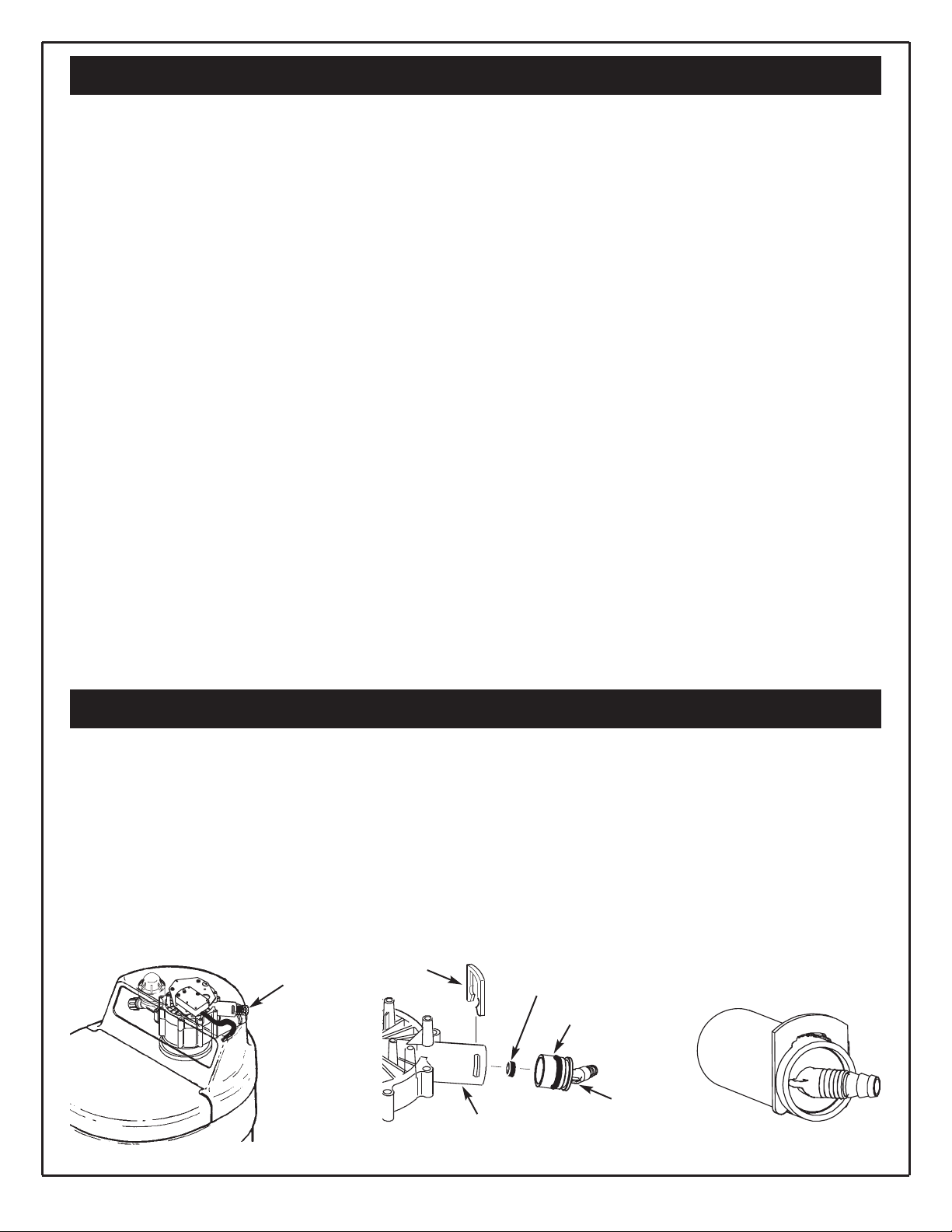
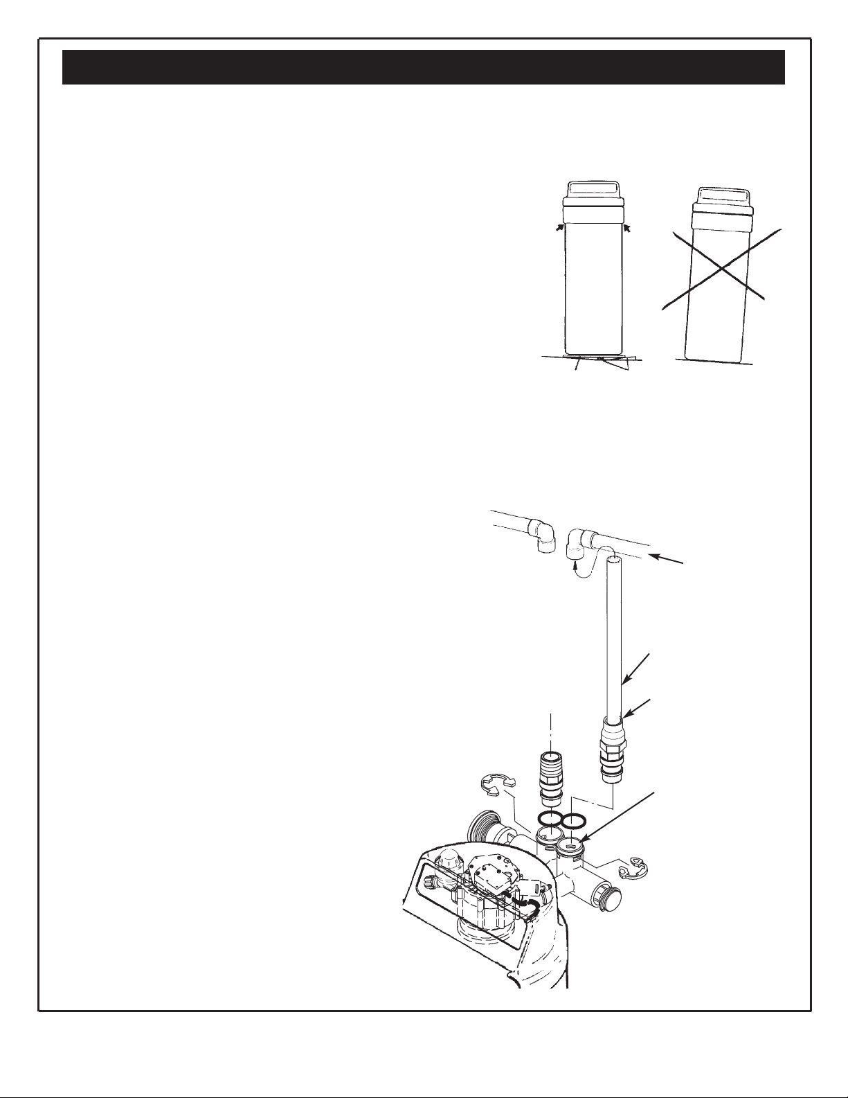
Remove
tube
Drain
elbow
Flow plug (should be
inside drain elbow)
Clip
O-ring
Drain port
Assemble Drain Port Elbow
A disposable piece of tubing has been installed in the
“drain” port of your new water softener to protect it
during shipping. Please do the following:
1. Remove the tube from the valve (See Figure A).
2. Locate the drain elbow that is attached to the installation accessories cardboard display (See Figure B).
3. Make sure that the black O-ring is attached to the outside of the drain elbow. Also look inside the drain
elbow to be sure the small black flow plug is inside and
hasn’t fallen out during shipping.
4. Insert the drain elbow into the valve’s “drain” port until
it stops and the black O-ring is pushed in beyond the
slots in the drain port with the smaller, barbed end
pointing out of the valve.
5. Secure the drain elbow to the valve using the black “U”
clip (also attached to the accessories cardboard display) by sliding it into the slots in the drain port and into
the grooves in the drain elbow (See Figure C).
6. Gently pull on the drain elbow to make sure it is secure
in the valve.
FIG. CFIG. A FIG. B
11
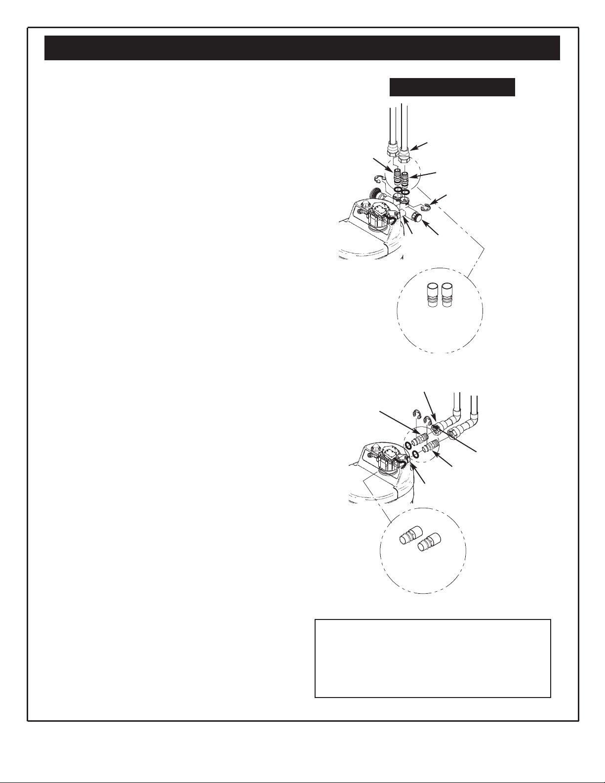
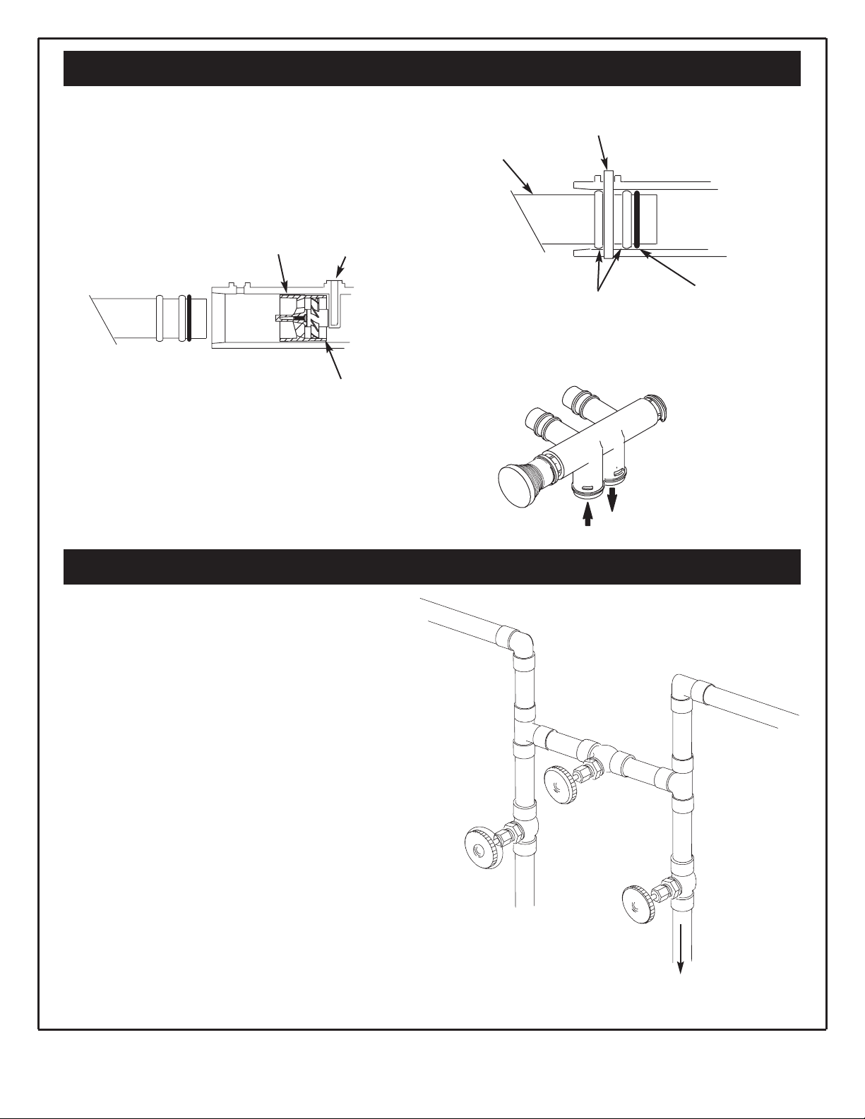
FIG. 9
INSTALLING BYPASS VALVE, AND/OR
INLET AND OUTLET THREADED ADAPTORS
Clip (2)
Valve Outlet
Included with
Softener
Included with
Softener
Valve Inlet
ASSEMBLE INLET OUTLET ADAPTORS,
OR PLASTIC BYPASS VALVE
Complete the following steps to assemble the adaptors or
bypass valve.
1. Close the shutoff valve on the house main water pipe,
near the water meter or pressure tank, to turn off the
water. See Fig. 7.
2. Shut off the gas or electric supply to the water heater.
See Fig. 7.
3. Open the highest and lowest water faucets in yourhouse. This will let water drain from the pipes. Close
faucets after water has drained.
4. Remove the main cover. See Fig. 8.
Pull outward on two (2) tabs to release.
The salt hole cover remains attached to the main cover
when removed. Set both covers aside so they will not get
scratched or broken.
INSTALL SEARS BYPASS VALVE AND / OR THE
INLET OUTLET THREADED ADAPTORS
NOTE: If you will not install the bypass valve because
you will have a three (3) valve bypass, skip steps 6 &
7, but do steps 5 and 8.
5. Visually check and remove any foreign materials from
the valve inlet and outlet ports. See Fig. 9. Carefully
remove the two large plastic clips (you will use them).
Check to be sure the turbine and turbine support are
firmly in place. See Fig. 10.
BYPASS VALVE:
6. Put a light coating of silicone grease on the o-ring seals
and slide onto the bypass valve.
7. Push the bypass valve into the softener valve as far as it
will go. Snap the two large holding clips into place,
from the top down as shown. See Fig. 11.
CAUTION: Be sure the clips snap firmly into place so
the bypass valve will not pull out. See Fig. 11.
INLET AND OUTLET THREADED ADAPTORS:
8. Put a light coating of silicone grease on the o-ring seals
and slide into the threaded adaptors. Push the adaptors
into the valve inlet and outlet ports, or bypass valve
ports, as far as they will go. Both adaptors are the same
and fit either port. Snap the two large holding clips
into place, as shown. See Fig. 11.
CAUTION: Be sure the clips snap firmly into place so
the tubes will not pull out. See Fig. 11.
Install Plastic Bypass Valve
FIG. 8
Salt Hole Cover
Cover (Main)
FIG. 7
Shutoff
Valve
Shutoff
Valve
Pressure
Tank
Well
Pump
Water
Meter
Electrical
Panel
Gas
Valve
Questions? Call The Kenmore Water Line 1-800-426-9345
12
Install 3-Valve Bypass
INSTALLING 3 VALVE BYPASS AND PIPES
Complete the following steps to install the three (3)
valve bypass:
• Cut the house main water pipe where you will con-
nect the softener.
• Loosely put together pipe, fittings, and the three
(3) valves.
• Place valve(s) within easy reach.
When all pipe, fittings and valves make a good fit
together, tighten all threaded joints (use pipe dope
on outside threads), or solder all sweat joints.
3 VALVE BYPASS
TO
Softener Inlet
FIG. 13
Questions? Call The Kenmore Water Line 1-800-426-9345
Install Plastic Bypass Valve
BYPASS VALVE TURNED DOWNWARD
IN
OUT
Turn bypass valve upside
down to connect to floor
level plumbing.
FIG. 12
FIG. 10
FIG. 11
INSTALLING HOLDING CLIPS
Black Clip
Cross Section of Valve
Inlet or Outlet
Bypass Valve or
Installation Adaptor
Clip Snaps into Place
Between Larger Diameter Rings
O-Ring
Before installing the bypass valve, or
copper tube, be sure the turbine and
support are firmly in place in the
valve outlet port.
Turbine
Support
Sensor Port
Turbine
13
Locate Water Softener and Connect Pipes
MOVE SOFTENER INTO PLACE
Grip under ridge
to move softener.
Plywood
Shims
TYPICAL SOLDERING
CONNECTIONS
Main Water Pipe
Hard Water
1. Cut pipe to
correct length.
2. Solder (WHEN
COOL, do Step 3).
3. Put threaded adaptor
into bypass valve
port.
4. Solder
NOTE: To be certain heat will
not travel down the pipe and
into the bypass valve (or
installation adaptors), wrap
the bottom of the pipe and the
bypass valve in a wet rag.
POSITION SOFTENER INTO PLACE
Complete the following steps to position the softener.
1. Grip under the ridge on the salt tank sidewall.
2. Carefully rock back and forth into position.
3. Move the softener into position.
4. Place on a level and smooth surface. If needed, put a
piece of 3/4” plywood, at least 17'' x 20'', under the
tank. Then put spacers under the plywood to level the
softener. See Fig. 14.
NOTE: Do not put shims or spacers directly under
the tank, without the plywood. The weight of the softener, when full of salt and water, may cause the tank
to puncture or break at the shim or spacer.
CONNECT THE SOFTENER
Refer to your plan drawing. See Fig. 5.
Measure, cut (thread if needed) and put all pipe and fittings together up to the main water pipe, or to the
bypass valve(s) you installed in the previous step.
CAUTION: Never solder fittings while connected to
nonmetallic parts. Wait until soldered pipe has
cooled before connection. See Fig. 15.
CAUTION: Be careful when putting pipe fittings
together. Do not cross thread, and do not overtighten.
FIG. 14
FIG. 15
Questions? Call The Kenmore Water Line 1-800-426-9345
14
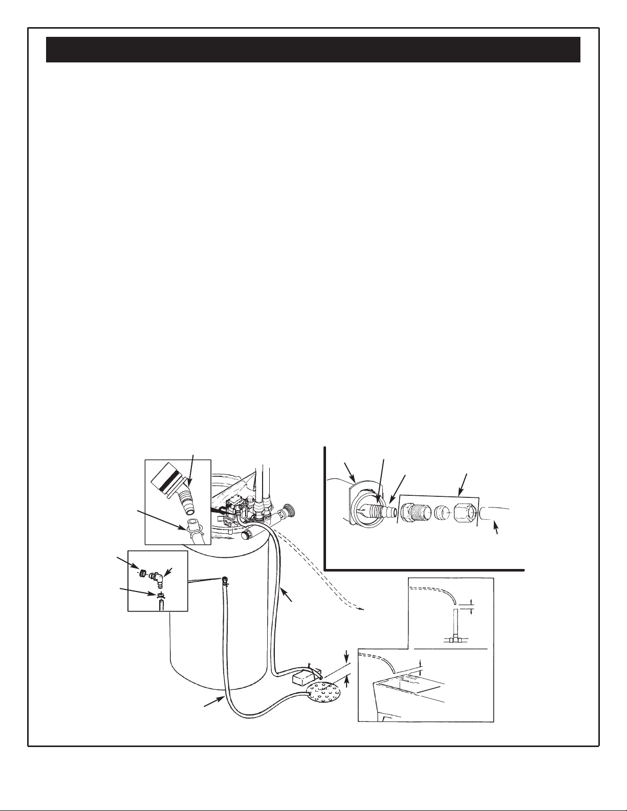
Connect Valve and Salt Tank Drains
CONNECT THE VALVE DRAIN HOSE
Take a length of 3/8” inside diameter drain tubing and
attach one end to the drain fitting. See Fig. 16. Use a
tube clamp to hold it in place. Put the other end of the
tubing over a floor drain, into a laundry tub, standpipe,
or other suitable drain. Check your local codes.
Leave an air gap of about 1-1/ 2'' between the end of
the hose and the drain. This gap is needed so you
don’t get a backflow of sewer water into the softener.
Do not put the end of the hose into the drain or connect without the air gap.
Place and support the hose so it does not kink or have
sharp bends. Secure the hose end so water pressure
does not cause the hose to “whip”. Tie or wire it in
place. Do not pinch the hose shut. The softener will
not work if this drain hose is pinched, plugged,
closed or restricted in any way. Direct drain flow
down into drain from drain line as flow could possibly
over shoot the drain cover.
Keep the hose lower than the drain fitting. In some
homes, to get to a drain you must raise the hose and
run it overhead. If you need an overhead drain, do not
raise the hose more than 8' above the floor. A copper
drain tube is best to use.
COPPER DRAIN TUBE: The local plumbing codes
may require the use a copper valve drain tube. A cop-
per tube is also best to use for an overhead drain. Use
a copper drain tube if the softener is installed outside,
or in the sunlight. Heat from the sun can soften, flatten
and close up some kinds of tubes.
To adapt a copper drain tube to the softener, buy a
compression fitting (1/4'' female pipe threads x 1/2''
O.D. tube) and tubing from your local hardware store.
CONNECT SALT TANK OVERFLOW TUBING
1. Locate the rubber grommet, tube adaptor and tube
clamp (see Fig. 16) that are in the parts bag.
2. Push the grommet into the hole in the salt tank wall
so half is inside and half is outside.
3. Push the bigger end of the tube adaptor into the
grommet.
4. Push one end of a length of 3/ 8'' I.D. tubing onto
the tube adaptor, using the tube clamp to hold it in
place.
5. Put the other end of the tubing over the floor drain.
IMPORTANT: Overflow water must run downward
through the tubing. Do not raise the tubing higher
than the grommet and tube adaptor. See Fig. 16.
IMPORTANT: Do not connect to the valve drain
hose you installed in step 1. Both drains must
have a separate hose or tube.
NOTE: Overflow drain tubing is available from
Sears. See parts list in back of manual.
Questions? Call The Kenmore Water Line 1-800-426-9345
Tube
Clamp
Drain
Fitting
Grommet
Tube
Adaptor
Tube
Clamp
1/4 NPT Threads
Barbs
1/2” Outside Diameter
Copper Tube (Not furnished)
Comp Fitting. 1/4 NPT x 1/2 in.
O.D. Tube (Not furnished)
Clip
Cut Barbs from
Drain Fitting (Pull
clip and remove
fitting from valve.)
1-1/2”
Air Gap
STANDPIPE
1-1/2” Air Gap
LAUNDRY TUB
FLOOR DRAIN
1-1/2”
Air Gap
Tie or Wire
Tubing in
Place
Valve Drain
Hose
To drain
point other
than floor
drain.
Support
tubing in
place as
needed.
Overflow Drain Tubing
NOTE: Overflow
drain tubing is available from Sears,
Item No. 42-3433
(20 ft).
FIG. 16
15
Leak Test
LEAK TEST
To check for leaks, complete the following steps:
CAUTION: To avoid water or air pressure damage to softener inner parts, and to flush pipe
chips or other residue from the water pipes, be
sure to do the following steps exactly as
instructed.
1. Fully open two cold, soft water faucets near the
softener.
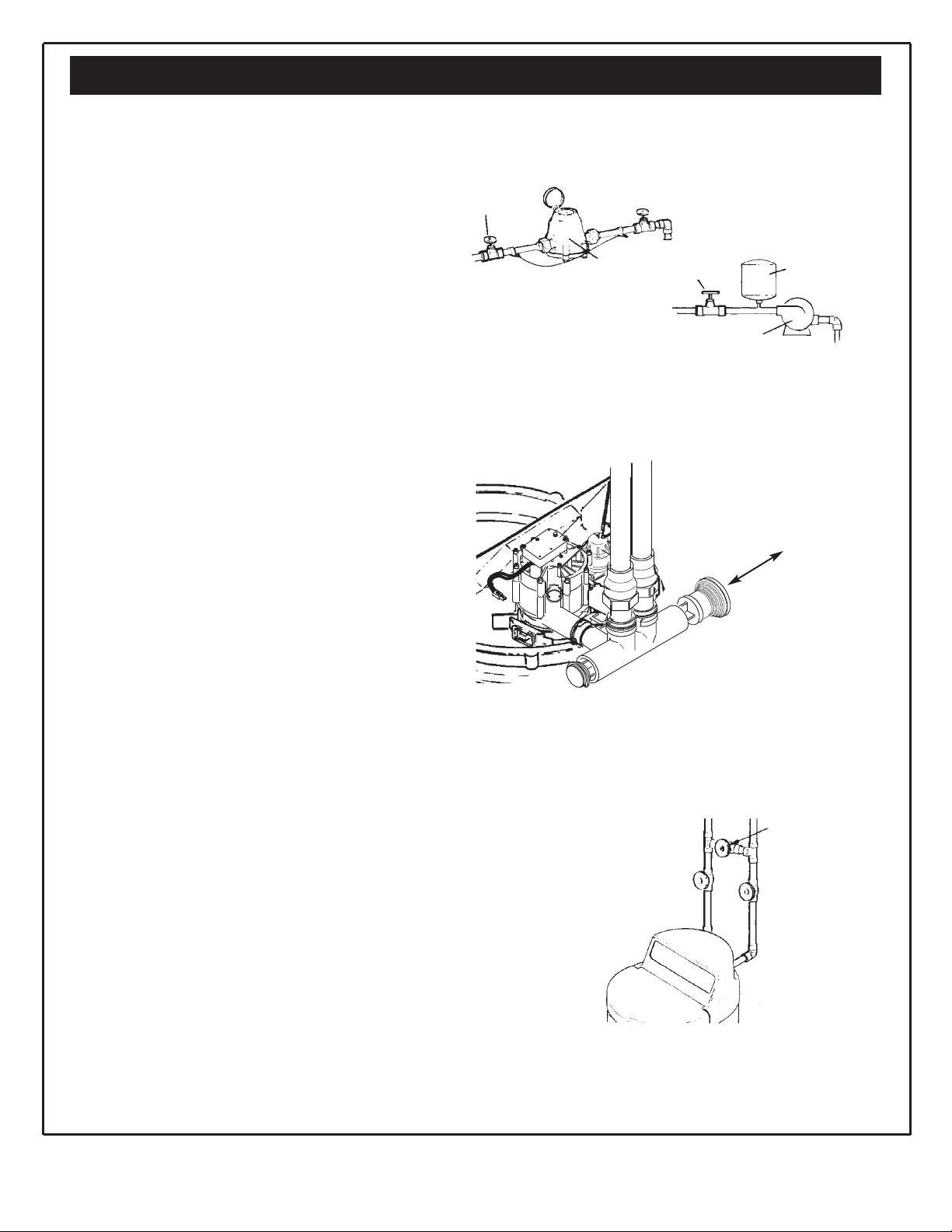
2. Look at the pictures in Fig. 18 and 19 to determine your kind of bypass valve(s). Place bypass
valve(s) in “bypass” position. On a single valve,
slide the stem inward to bypass. On a three (3)
valve system, close the inlet and outlet valves and
open the bypass valve.
3. Fully open the house main water pipe shutoff
valve. Observe steady water flow from both open
faucets.
4. Place bypass valve(s) in SERVICE EXACTLY as
follows: Keep soft water faucets open.
a. Single Bypass Valve: Slowly, slide pull the
valve stem outward toward service, pausing several times to allow the softener to pressurize slowly.
b. Three Valve Bypass: Fully close the bypass
valve and open the outlet valve. Slowly, open the
inlet valve, pausing several times to allow the softener to pressurize slowly.
5. After about three minutes, open a hot water
faucet for about one minute, or until all air is
expelled, then close.
6. Close both cold water faucets.
7. Check your plumbing work for leaks and fix right
away if any are found. Be sure to observe previ-
ous caution notes.
NOTE: If this procedure is performed on a new
softener, water coming from the taps may initially be discolored. This normally occurs the first
time water runs through the resin bed. The discolored water is not harmful, and the discoloration will not last more than a few minutes.
HOUSE MAIN WATER
SHUTOFF VALVES
Shutoff Valve
Water
Meter
Shutoff Valve
Pressure Tank
Well Pump
SINGLE BYPASS
Pull Stem Outward
For Service
Push Inward
For Bypass
VALVE BYPASS
FOR SERVICE
Close bypass valve.
Open inlet & outlet
valves.
FOR BYPASS
Open bypass valve.
Close inlet & outlet
valves.
Outlet
Valve
Bypass
Valve
Inlet
Valve
FIG. 18
FIG. 19
FIG. 17
Questions? Call The Kenmore Water Line 1-800-426-9345
Note: Stem may be installed
in either direction. The end
with writing should be pulled
out for service position.
 Loading...