

Kenmore 625.3835 User Manual

Use & Care Guide Manual de Uso y Cuidado
English / Español
Model / Modelo No. 625.383500
Kenmore
V
...
N5
«
Nf
Norma f
IMSIF/A,N5
....
ISIF/AIN
Water So
with High F
Ablandador d
con vélvu o flujo
Sears Brands Management Corporation
Hoffman Estates, IL 60179 U.S.A.
www.kenmorewater.com
www.kenmore.com
www.seors.com
©
Printed on recycled paper/
Impreso en papel reciclado
P/N 7325207 (Rev. A 12/22/10)

Warranty
WARRANTY ON KENMORE WATER SOFTENER
ONE YEAR LIMITED WARRANTY ON WATER SOFTENER
When installed, operated and maintained according to all instructions supplied with the product, if this
Kenmore appliance foils due to a defect in material and workmanship within one year from the date of pur
chase, call 1-800-4-MY-HOME® to arrange for free repair.
TEN YEAR LIMITED WARRANTY AGAINST LEAKS
When installed, operated and maintained according to all instructions supplied with the product, if the water
softener tank or salt storage drum develops a leak within ten years from the date of purchase,
coll 1-800-4-MY-HOME* to arrange for free tank or drum replacement. After the first year you must pay on
initial trip charge.
All warranty coverage does not include water softener resin, which is an expendable item.
If this appliance is used for other than private family purposes, this warranty applies for only 90 days from
the date of purchase.
This warranty covers only defects in material and workmanship. Sears will NOT pay for:
1. A service technician to instruct the user in correct product installation, operation or maintenance.
2. A service technician to clean or maintain this product.
3. Damage to or failure of this product if it is not installed, operated or maintained according to the all
instructions supplied with the product.
4. Damage to or failure of this product resulting from accident, abuse, misuse or use for other than its intend
ed purpose.
5. Damage to or failure of this product caused by the use of detergents, cleaners, chemicals or utensils other
than those recommended in all instructions supplied with the product.
6. Damage to or failure of parts or systems resulting from unauthorized modifications made to this product.
Disclaimer of implied warranties; limitation of remedies
Customer’s sole and exclusive remedy under this limited warranty shall be product repair as provided herein.
Implied warranties, including warranties of merchantability or fitness for a particular purpose, are limited to
one year or the shortest period allowed by law. Sears shall not be liable for incidental or consequential dam
ages. Some states and provinces do not allow the exclusion or limitation of incidental or consequential dam
ages, or limitation on the duration of implied warranties of merchantability or fitness, so these exclusions or
limitations may not apply to you.
This warranty applies only while this appliance is used in the United States or Canada.
This warranty gives you specific legal rights, and you may also have other rights which vary from state to
state.
Sears Brands Management Corporation, Hoffman Estates, IL 60179 U.S.A.
Questions? Call the Kenmore Water Line 1-800-426-9345 or visit www.kenmorewater.com

Table of Contents
Warranty.......................................................
Safety Guides...............................................
Specifications & Dimensions
Packing List .................................................
Plan Your Installation
Installation....................................................
Programming the Softener...........................
Sanitizing the Water Softener . . . . ......................................14
Adding Salt to the Storage Tank . . ......................................14
Controller Features
Care of Your Water Softener
Service Information........................................ .................................19-22
Exploded View & Parts List
......................................
......................
..................................
........................
.........................
........................................
........................................
........................................
........................................
...................................
...................................
.................................12-13
.................................15-18
......................................19
..............................
5-7
7-11
24-27
Safety Guides
▲ Read all steps and guides carefully before installing
and using your new water softener. Follow all steps
exactly to correctly install. Failure to follow them
could cause personal injury or property damage.
Reading this manual will also help you to get all the
benefits from your water softener.
▲ Your Kenmore water softener will remove hardness
minerals from water. This is measured in grains per
gallon (gpg). It will also remove some clear water
iron*. This is measured in parts per million (ppm).
See the specifications page for the maximum limits
of hardness and iron removal.
▲ A water softener will not improve other water prob
lems such as acidity, tastes and odors, or iron other
than clear water iron.
▲ Do not attempt to use this product to make safe
drinking water from non-potable water sources. Do
not use the system on microbiologically unsafe water,
or water of unknown quality without adequate disin
fection before or after the system.
▲ Check with your local public works department for
plumbing and sanitation codes. You must follow
their guides as you install the system. Follow your
local codes if they differ with guides in this manual.
In Massachusetts, plumbing code 248-CMR 3.00 and
10.00 shall be adhered to. Consult with a licensed
plumber.
▲ Use only lead-free solder and flux for all sweat-solder
connections, as required by federal codes, when
installing soldered copper plumbing.
▲ Use care when handling the water softener. Do not
turn upside down or drop.
▲ Avoid installing in direct sunlight. Excessive heat may
cause distortion or other damage to non-metallic
parts.
▲ This water softener works on water pressures of 20 psi
(minimum) to 125 psi (maximum). If your house water
pressure is over the maximum, install a pressure reduc
ing valve in the water supply pipe to the softener.
▲ This softener works on 24 volt, 60 FIz electrical power
only, supplied by a direct plug-in transformer (includ
ed). Be sure to use the included transformer and plug
it into a nominal 120V, 60 cycle household outlet that
is properly protected by an overcurrent device such as
a circuit breaker or fuse. If transformer is replaced,
use only the authorized service. Class II, 24V lOVA
transformer.
▲ Do not install the water softener outside, or in extreme
hot or cold temperatures. Temperature of the water
supply to the water softener must be between 40°F
and 120°F. Do not install on hot water.
* The capacity to reduce clear water iron is substantiated
by Water Quality Association test data.
2
3
4
5
European Directive 2002/96/EC requires all electrical and electronic
equipment to be disposed of according to Waste Electrical and Electronic
Equipment (WEEE) requirements. This directive or similar laws are in
place nationally and can vary from region to region. Please refer to your
state and local laws for proper disposal of this equipment.
Questions? Call the Kenmore Water Line 1-800-426-9345 or visit www.kenmorewater.com
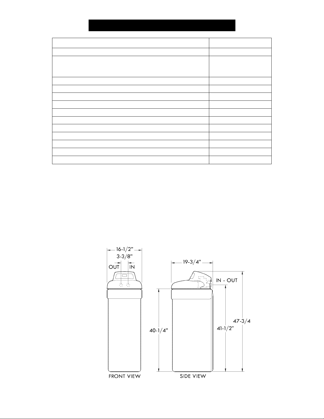
Specifications & Dimensions
Model No. 625.383500
Model Code
12,600 @ 2.5 lbs.
Rated Softening Capacity (Grains @ Salt Dose)
Rated Efficiency (Grains/Pound of Salt @ Minimum Salt Dose)
Rated Service Flow Rate
Amount of Fligh Capacity Ion Exchange Resin 0.83 cu. ft.
Pressure Drop at Rated Service Flow 10 psig
Water Supply Max. Hardness
Water Supply Max. Clear Water Iron 11 ppm*
Water Pressure Limits (minimum / maximum)
Water Temperature Limits (minimum / maximum)
Minimum Water Supply Flow Rate 3 gpm
Intermittent Flow @ 15 psi 10 gpm**
Maximum Drain Flow Rate
*Capacity to reduce clear water iron is substantiated by WQA test data. State of Wisconsin
requires additional treatment if water supply contains clear water iron exceeding 5 ppm.
**lntermittent flow rate does not represent the maximum service flow rate used for detemi-
ning the softener’s rated capacity and efficiency. Continuous operation at flow rates
greater than the service flow rate may affect capacity and efficiency performance.
These systems conform to NSF/ANSI 44 for the specific performance claims as verified and
substantiated by test data.
The efficiency rating is only valid at the stated salt dose. These softeners were efficiency
rated according to NSF/ANSI Standard 44.
Variable Salt Dose: The salt dose is selected by the electronic controls at regeneration time
based on the amount needed.
26,900 @ 7.9 lbs.
32,100 @ 13.3 lbs.
350
5,090 @ 2.5 lbs.
8.0 gpm
90 gpg
20 - 125 psi
40 - 120 °F
2.0 gpm
Figure 1
Questions? Call the Kenmore Water Line 1-800-426-9345 or visit www.kenmorewater.com
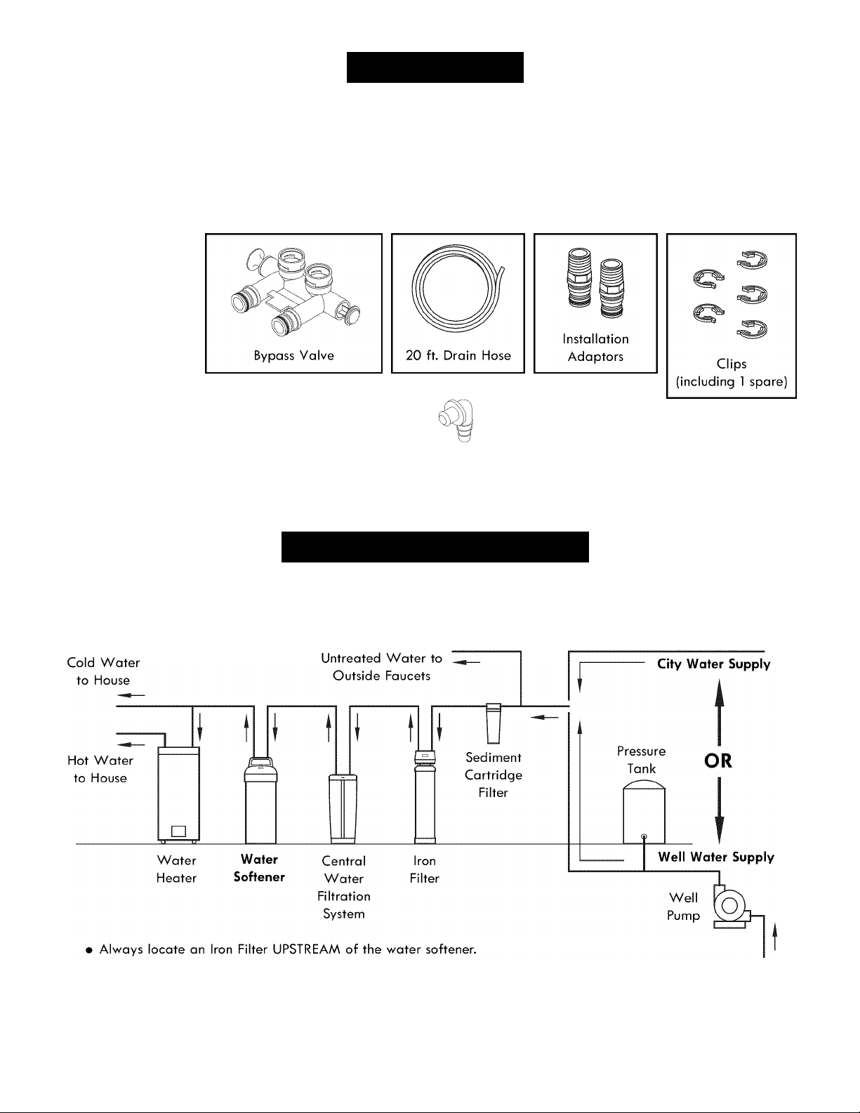
Packing List
The parts required to assemble and install the water
softener ore included with the unit. Thoroughly check
the water softener for possible shipping damage and
ports loss. Also inspect and note any damage to the
shipping carton.
Ground Clamp
Kit
Hose Clamps Adaptor Elbow
Remove and discard (or recycle) oil packing materials.
To ovoid loss of small ports, we suggest you keep the
small parts in the ports bag until you ore ready to use
them.
Small Parts
' ^
Grommet
Figure 2
Plan Your Installation
THE PROPER ORDER TO INSTALL WATER TREATMENT EQUIPMENT
(Shows sequence of equipment only - not all items are needed in all applications)
• Locate a Central Water Filtration System UPSTREAM of the water softener on a chlorinated
water supply, or DOWNSTREAM of the water softener on a non-chlorinated water supply.
Figure 3
Questions? Call the Kenmore Water Line 1-800-426-9345 or visit www.kenmorewater.com
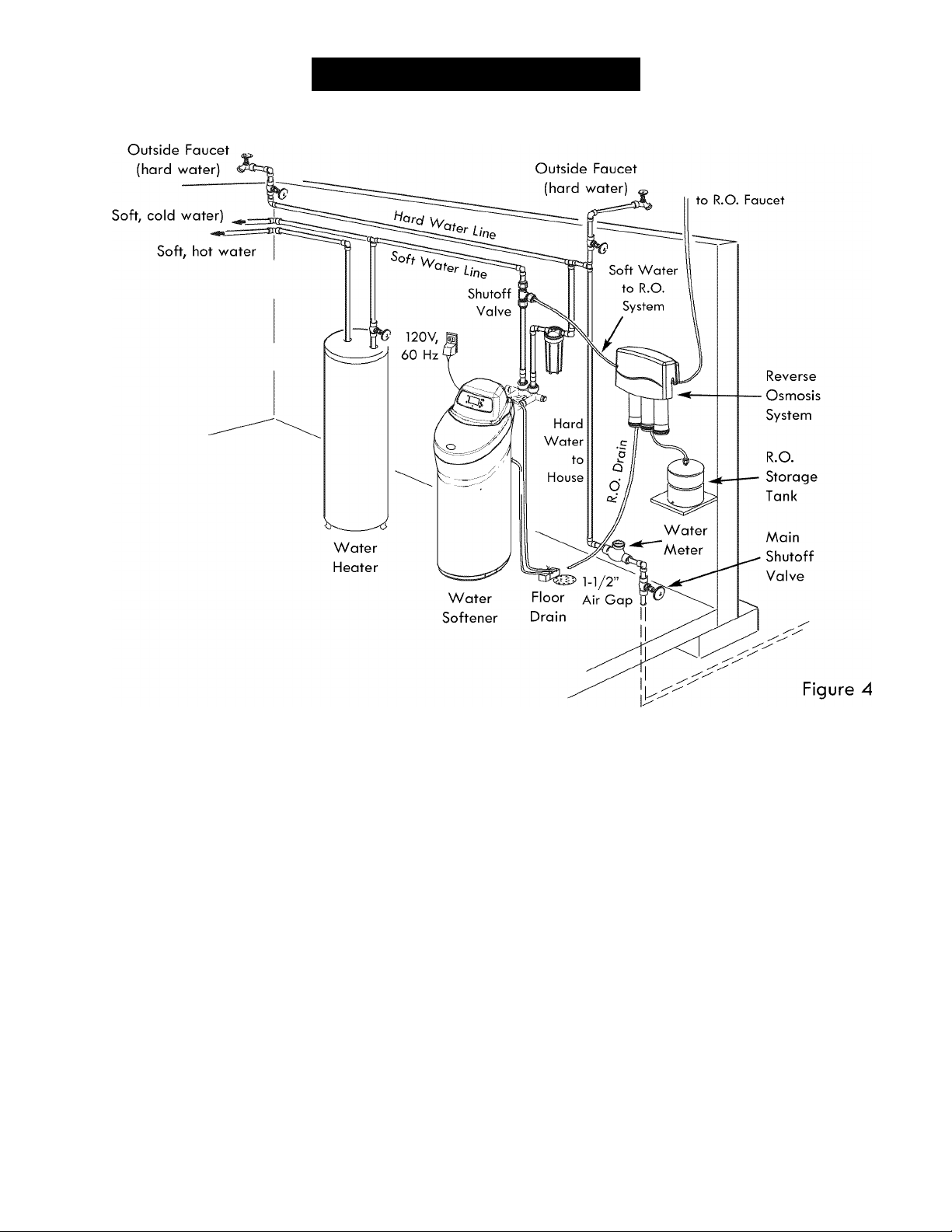
Plan Your Installation
TYPICAL INSTALLATION
WHERE TO INSTALL THE WATER SOFTENER
Review the following points before you choose a place
to put your softener:
1. Place as close as possible to, but always downstream
from, the pressure tank (well water) or water meter
(city water).
2. Place as close as possible to a water drain such as a
floor drain, laundry tub, sump or standpipe (See Fig.
4).
3. Connect to the house main water pipe UPSTREAM
OF THE WATER HEATER (See Fig. 3). The tempera
ture of water going through the softener must not be
more than 120°F (49°C). Hot water will damage
inner softener parts. To reduce the risk of hot water
backup, piping between the softener and water
heater should be as long as possible.
4. Keep outside faucets on hard water to save soft
water and salt. See Fig. 4.
5. Do not install in a place where the softener could
freeze. Damage caused by freezing voids the war
ranty by Sears Brands Management Corporation.
6. Put the softener in a place where water damage is
least likely to occur if it develops a leak. Sears or
the manufacturer will not repair or pay for water
damage.
7. A grounded, 120V, 60 Hz. electrical outlet is needed
within 10 feet of the softener to plug in the trans
former (See Fig. 4). Be sure the outlet and trans
former are in an inside location, protected from wet
weather. Use a continuously “live” outlet, which can
not be accidentally switched off.
8. When installing in an outside location, you must take
the steps necessary to assure the softener, installation
plumbing, and wiring, are protected from the ele
ments, direct sunlight, contamination, vandalism, etc.
Questions? Call the Kenmore Water Line 1-800-426-9345 or visit www.kenmorewater.com
6
Plan Your Installation
CHECK YOUR WATER PRESSURE BEFORE INSTALLING
For your water softener to work properly, incoming
water pressure in your house pipes must be no lower
than 20 pounds per square inch (psi). The highest
allowable pressure is 125 psi. If pressure is above 125
psi, buy and install a pressure reducing valve in the
pipe supplying water to the softener’s inlet.
NOTE: If water pressure during the day is 100 psi or
more, pressure during the night may go above
125 psi.
nstallation
INSTALL SINGLE BYPASS VALVE AND/OR THREADED INSTALLATION ADAPTORS
SINGLE BYPASS VALVE:Complete the following steps to assemble the adaptors
and/or the included single bypass valve.
1. Close the shutoff valve on the house main water pipe,
near the water meter or pressure tank, to turn off the
water.
2. Shut off the gas or electric supply to the water
heater.
3. Open the highest and lowest water faucets in your
house. This will let water drain from the pipes.
Close faucets after water has drained.
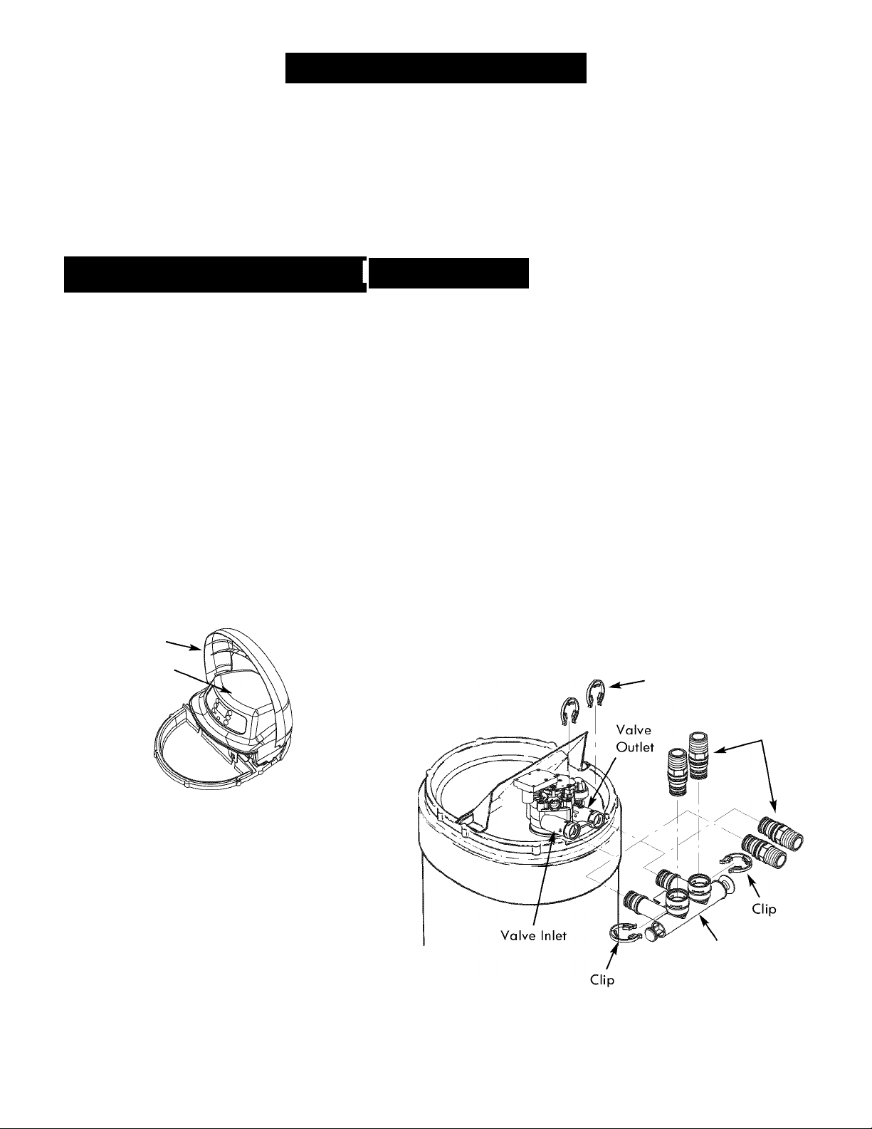
4. Remove the top cover. Pull outward on the two tabs
to release top cover (see Fig. 5). The salt lid remains
attached to the top cover when removed. Set both
covers aside so they will not get scratched or broken.
Salt Lid
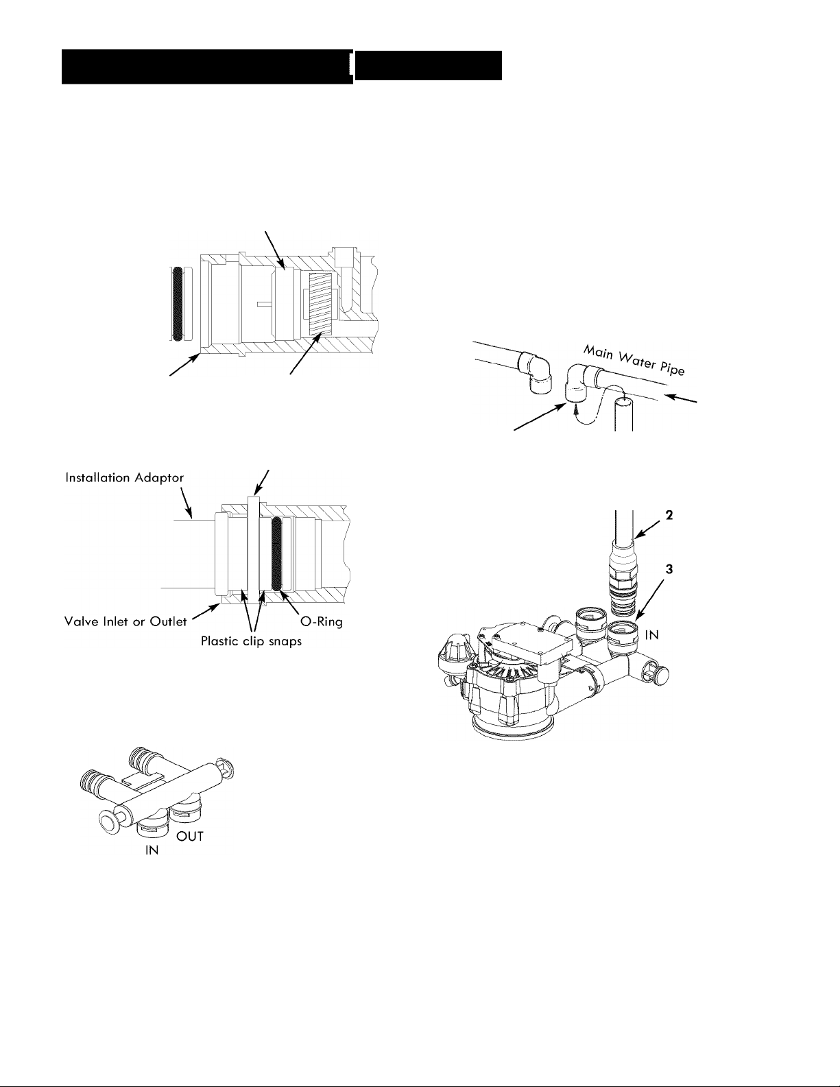
6. Push the bypass valve into the softener valve’s inlet
and outlet ports as far as it will go. Snap the two
large holding clips into place, from the top down as
shown (see Fig. 8).
CAUTION: Be sure the clips snap firmly into place so
the bypass valve will not pull out.
INLET AND OUTLET THREADED ADAPTORS:
7. Push the adaptors into the valve inlet and outlet
ports, or bypass valve ports, as far as they will go.
Both adaptors are the same and fit either port. Snap
the two large holding clips into place, as shown (see
Fig. 8).
CAUTION: Be sure the clips snap firmly into place so
the adaptors will not pull out.
Top Cover
Clips
Figure 5
5. Visually check and remove any foreign mate
rials from the valve inlet and outlet ports (see
Fig. 6). Carefully remove the two large plastic
clips (you will use them). Check to be sure
the turbine and support are firmly in place
(see Fig. 7).
NOTE: If you will not install the included bypass
valve because you will have a 3-valve
bypass in your plumbing, skip step 6, but
perform step 7.
Single
Bypass Valve
Questions? Call the Kenmore Water Line 1-800-426-9345 or visit www.kenmorewater.com
Threaded
Installation
Adaptors
Figure 6
nstallatìon
INSTALL SINGLE BYPASS VALVE (coni.)
Before installing the bypass valve and/or installation
adaptors, make sure that the turbine and support are
firmly in place inside the softener valve’s outlet port.
Turbine
Support
Valve Outlet Turbine
Figure 7
INSTALL HOLDING CLIPS
Bypass Valve or Plastic Clip
ASSEMBLE INLET AND OUTLET PLUMBING
Measure, cut (thread if needed) and put together all
pipe and fittings up to the main water pipe. Make sure
that the incoming water supply pipe goes to the valve
inlet side.
CAUTION: Never solder fittings while connected to
nonmetallic parts. Wait until soldered pipe
has cooled before connection. See Fig. 10.
CAUTION: Be careful when putting pipe fittings togeth
er. Do not cross thread, and do not over
tighten.
Incoming
Hard
Water
4. Solder.
NOTE: To be certain
that heat will not
travel down the pipe
and into the bypass
valve or installation
adaptors, wrap the
bottom of the pipe
and the bypass valve
with a wet rag.
1. Cut pipe to
correct length
Solder. When
cool, do step 3.
Put threaded
adaptor into
bypass valve
port.
into groove in
bypass or adaptor
ALTERNATE BYPASS VALVE INSTALLATION
If connecting to floor
level plumbing, install
the bypass valve turned
downward, as shown.
Figure 8
Figure 10
Figure 9
Questions? Call the Kenmore Water Line 1-800-426-9345 or visit www.kenmorewater.com
nstallation
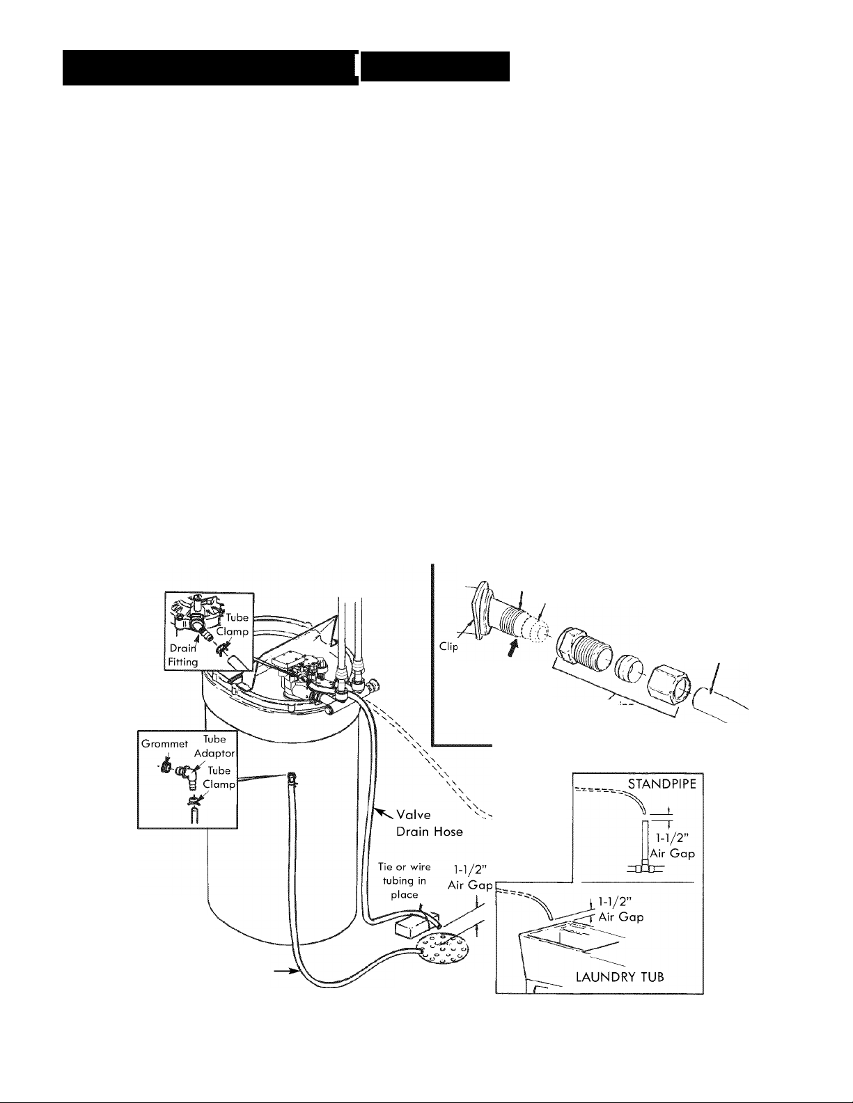
CONNECT THE VALVE DRAIN HOSE
Take a length of 3/8” inside diameter drain tubing
(supplied) and attach one end to the drain fitting (see
Fig. n). Use a tube clomp from the ports bag to hold it
in place. Put the other end of the tubing over a floor
drain, into a laundry tub, standpipe, or other suitable
drain. Check your local codes.
Leave an air gap of about 1-1/ 2" between the end of
the hose and the drain. This gap is needed so you
don’t get o backflow of sewer water into the softener.
Do not put the end of the hose into the drain or con
nect without the air gap.
Locate and support the hose so it does not kink or hove
sharp bends. Secure the hose end so water pressure
does not cause the hose to “whip”. Tie or wire it in
place. Do not pinch the hose shut. The softener will
not work if this drain hose is pinched, plugged, closed
or restricted in any way. Direct drain flow down into
drain from drain line as flow could possibly overshoot
the drain cover.
Keep the hose lower than the drain fitting. In some
homes, to get to a drain you must raise the hose and
run it overhead. Do not raise the hose more than 8 feet
above the floor.
COPPER DRAIN TUBE: Local plumbing codes may
require the use a copper valve drain tube. A copper
tube is also best to use if running a drain line overhead.
To adapt a copper drain tube to the softener, purchase
a compression fitting (1/4" female pipe threads x 1/2"
0. D. tube) and tubing from your local hardware store.
CONNECT SALT TANK OVERFLOW HOSE
1. Locate the rubber grommet, adaptor elbow and tube
clamp (see Fig. 11) that are in the parts bag.
2. Push the grommet into the hole in the salt tank wall
so that half is inside and half is outside.
3. Push the larger end of the adaptor into the grommet.
4. Push one end of a length of 3/8" I.D. tubing (sup
plied) onto the tube adaptor, using a tube clamp
from the parts bag to hold it in place.
5. Put the other end of the tubing over the floor drain.
IMPORTANT: Overflow water must run down by gravity
through the tubing. Do not raise the tub
ing higher than the adaptor (see Fig. 11).
IMPORTANT: Do not connect this hose to the valve
drain hose you just installed (see above).
Both drains must have a separate hose.
NOTE: Drain Hose
(20 ft.) is included.
See also parts list.
Salt Tank
Overflow Hose
Cut barbs from
drain fitting (pull
clip and remove
fitting from valve)
FLOOR DRAIN
1/4 NPT
Threads
Compression Fi
1/4 NPT X 1/2” O.D.
To drain
point other
than floor
drain.
Support tub
ing in place
as needed.
SUBSTITUTING RIGID DRAIN LINE
Barbs
1/2” Outside
Diameter Copper
Tube (not supplied)
Tube (not supplied)
Figure 11
Questions? Call the Kenmore Water Line 1-800-426-9345 or visit www.kenmorewater.com
 Loading...