


Kenmore 46782, 46781, 46893 Quick Start Manual
United States
INSTALLATION AND SERVICEMUST BEPERFORMED BY A QUALIFIED INSTALLER.
IMPORTANT: SAVE FOR LOCAL ELECTRICAL INSPECTOR'S USE.
READ AND SAVE THESE INSTRUCTIONS FOR FUTURE REFERENCE.
FOR YOUR SAFETY: Do not store or use gasoline or other
flammable vapors and liquids in the vicinity of this or any other appliance.
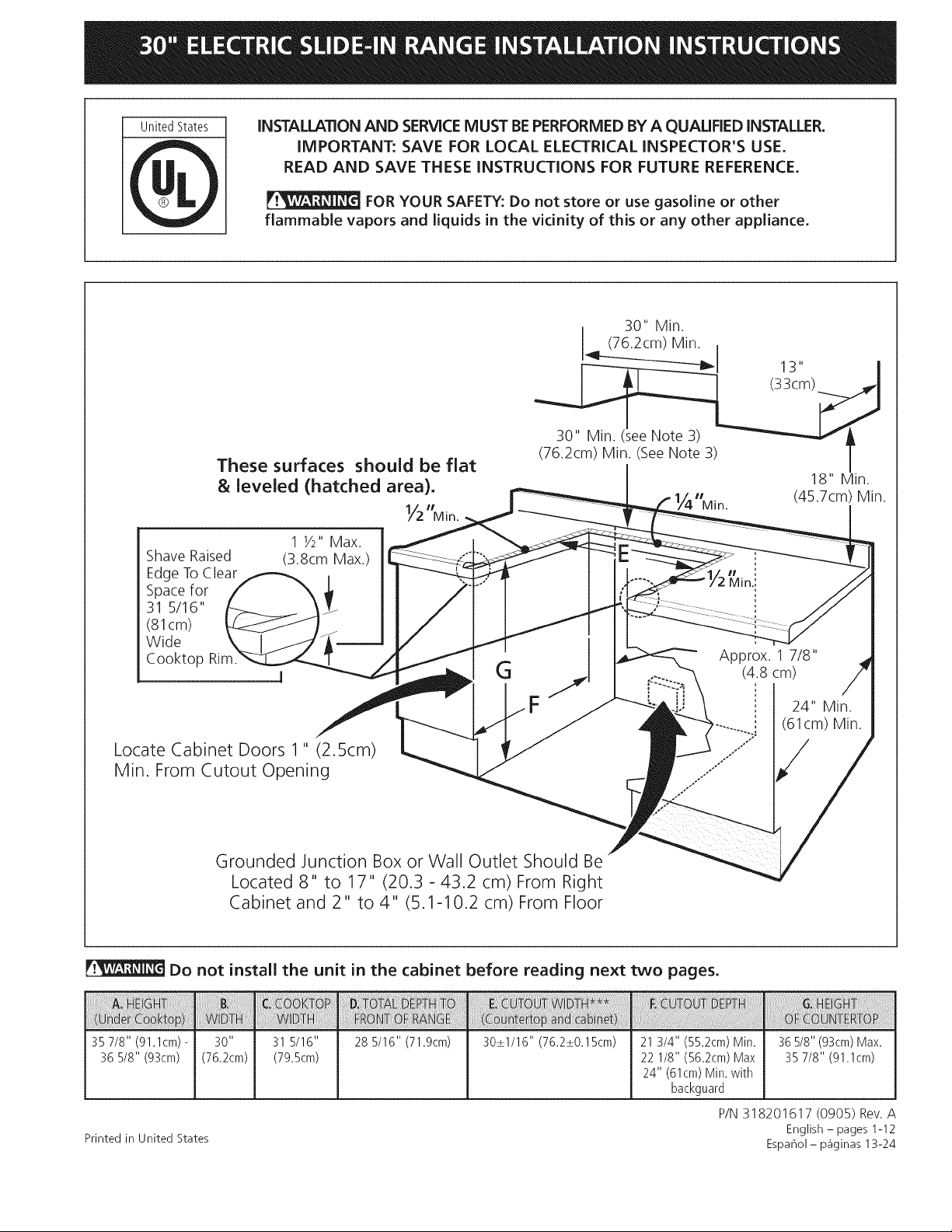
30" Min.
(76.2cm) Min. ,
These surfaces should be flat
& leveled (hatched area).
1 1/2"Max.
Shave Raised
(3.8cm Max.)
Edge ToClear
Spacefor
31 5/16"
(81cm)
Wide
Cooktop
Locate Cabinet Doors 1" (2.5cm)
Min. From Cutout Opening
Grounded Junction Box or Wall Outlet Should Be
Located 8" to 17" (20.3 - 43.2 cm) From Right
Cabinet and 2" to 4" (5.1-10.2 cm) From Floor
Y2"Mio.
(76.2cm) Min. See Note 3) /
Min. (45.7cm) Min.
G (4.8 cm)
Approx. 1 7/8"
F
18" Min.
24" Min.
(61cm) Min.
Do not install the unit in the cabinet before reading next two pages.
35 7/8" (91.1cm) - 31 5/16" 28 5/16" (71.9cm) 30_+1/16" (76.2_+0.15cm) 21 3/4" (55.2cm) Min.
36 5/8" (93cm) (79.5cm) 22 1/8" (56.2cm) Max
24" (61cm) Min. with
backguard
P/N 318201617 (0905) Rev. A
Printed in United States
36 5/8" (93cm) Max.
35 7/8" (91.1cm)
English - pages 1-12
Espahol - p_iginas 13-24
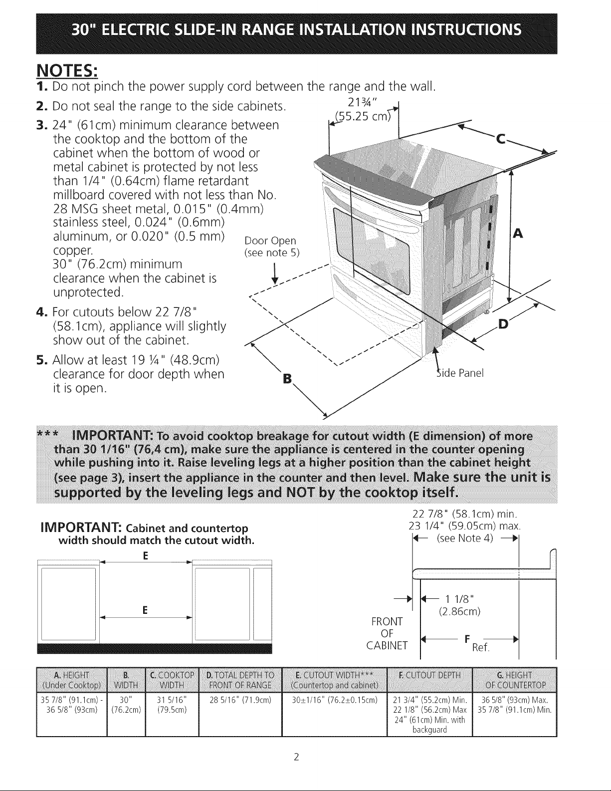
NOTES:
1. Do not pinch the power supply cord between the range and the wall.
2. Do not seal the range to the side cabinets. 213/_"
3.24" (61cm) minimum clearance between
the cooktop and the bottom of the
cabinet when the bottom of wood or
metal cabinet is protected by not less
than !/4" (0.64cm)flame retardant
millboard covered with not less than No.
28 MSG sheet metal, 0.015" (0.4mm)
stainless steel, 0.024" (0.6mm)
aluminum, or 0.020" (0.5 mm)
copper.
30" (76.2cm) minimum
clearance when the cabinet is
unprotected.
4. For cutouts below 22 7/8"
(58.1cm), appliance will slightly
show out of the cabinet.
5. Allow at least 19 ¼" (48.9cm)
clearance for door depth when
it is open.
Door Open
(see note 5)
1
/
/
A
ide Panel
IMPORTANT: Cabinet and countertop
width should match the cutout width.
E
35 7/8" (91.1cm) -
36 5/8" (93cm)
31 5/16"
(79.5cm)
28 5/16" (71.9cm) 30_+1/16" (76.2_+0.15cm) 21 3/4" (55.2cm) Min.
FRONT
OF
CABINET
22 1/8" (56.2cm) Max
24" (61cm) Min. with
22 7/8" (58.1 cm) min.
23 1/4" (59.05cm)max.
(see Note 4) _ ["
1 1/8"
(2.86cm)
Ref.
36 5/8" (93cm) Max.
35 7/8" (91.1cm) Min.
backguard
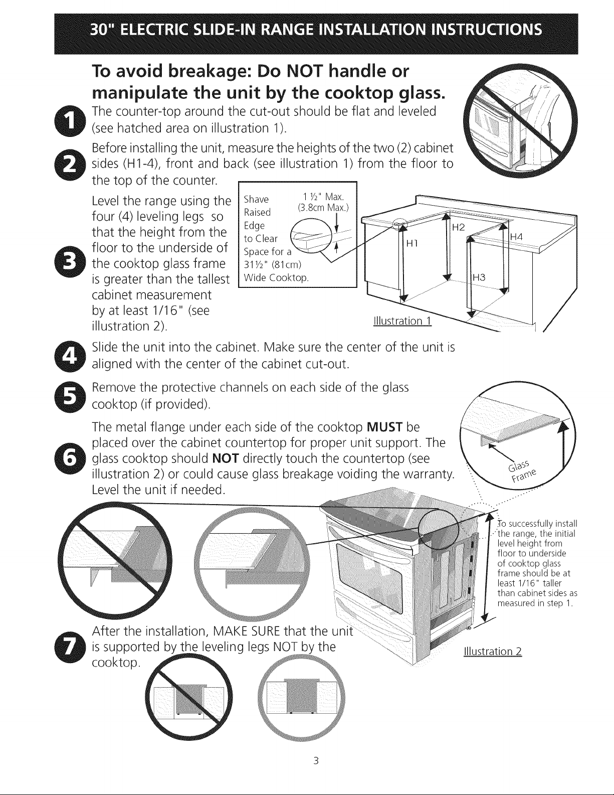
To avoid breakage: Do NOT handle or
manipulate the unit by the cooktop glass.
The counter-top around the cut-out should be flat and leveled
(see hatched area on illustration 1).
Before installing the unit, measure the heights of the two (2) cabinet
sides (H1-4), front and back (see illustration 1) from the floor to
the top of the counter.
Level the range using the
four (4)leveling legs so
that the height from the
floor to the underside of
the cooktop glass frame
is greater than the tallest
Shave
Raised
Edge
to Clear
Spacefor
311/2" (81cm)
Wide Cooktop.
cabinet measurement
by at least 1/16" (see
illustration 2).
Slide the unit into the cabinet. Make sure the center of the unit is
aligned with the center of the cabinet cut-out.
1 1/2"Max.
(3.8cmMax.)
Illustration 1
Remove the protective channels on each side of the glass
cooktop (if provided).
The metal flange under each side of the cooktop MUST be
placed over the cabinet countertop for proper unit support. The
glass cooktop should NOT directly touch the countertop (see
illustration 2) or could cause glass breakage voiding the warranty.
Level the unit if needed.
After the installation, MAKE SUREthat the uni
is supported by the leveling legs NOT by the
cooktop.
.-Tosuccessfully install
range, the initial
level height from
floor to underside
of cooktop glass
frame should be at
least 1/16" taller
than cabinet sides as
measured in step 1.
Illustration 2
3
Important Notes to the Installer
1. Read all instructions contained in these installation
instructions before installing range.
2. Remove all packing material from the oven compartments
before connecting the electrical supply to the range.
3. Observe all governing codes and ordinances.
4. Be sure to leave these instructions with the consumer.
Important Note to the Consumer
Keep these instructions with your owner's guide for future
reference.
IMPORTANT SAFETY
INSTRUCTIONS
• Be sure your range is installed and grounded
properly by a qualified installer or service
technician.
• This range must be electrically grounded in
accordance with local codes or, in their absence,
with the National Electrical Code ANSI/NFPA No.
70--latest edition in United States
• The installation of appliances designed for
manufactured (mobile) home installation must conform
with Manufactured Home Construction and Safety
Standard, title 24CFR, part 3280 [Formerly the Federal
Standard for Mobile Home Construction and Safety,
title 24, HUD (part 280)] or when such standard
is not applicable, the Standard for Manufactured
Home Installation 1982 (Manufactured Home Sites,
Communities and Setups), ANSI Z225.1/NFPA 501A-
latest edition, or with local codes in United States.
Stepping, leaning or sitting on the
door or drawer of this range can result in serious
injuries and can also cause damage to the range.
• Do not store items of interest to children in
the cabinets above the range. Children could be
seriously burned climbing on the range to reach items.
• To eliminate the need to reach over the surface
units, cabinet storage space above the units
should be avoided.
• Do not use the oven as a storage space. This
creates a _otentially hazardous situation.
• Never use your range for warming or heating the
room. Prolonged use of the range without adequate
ventilation can be dangerous.
• Do not store or use gasoline or other flammable
vapors and liquids near this or any other
appliance. Explosions or fires could result.
• Reset all controls to the "off" position after using
a programmable timing operation,
FOR MODELS WITH SELF-CLEAN FEATURE:
• Remove broiler pan, food and other utensils
before self-cleaning the oven, Wipe up excess
spillage. Follow the precleaning instructions in the
Owner's Guide.
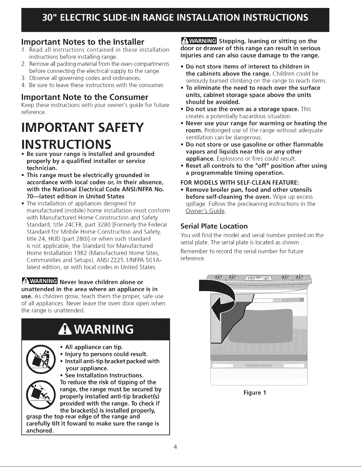
Serial Plate Location
You will find the model and serial number printed on the
serial plate. The serial plate is located as shown.
Remember to record the serial number for future
reference.
Never leave children alone or
unattended in the area where an appliance is in
use. As children grow, teach them the proper, safe use
of all appliances. Never leave the oven door open when
the range is unattended.
• AlL appliance can tip.
• Injury to persons could result.
• Install anti-tip bracket packed with
your appliance.
• See Installation Instructions,
range, the range must be secured by
properly installed anti-tip bracket(s)
To reduce the risk of tipping of the
provided with the range, To check if
the bracket(s) is installed properly,
grasp the top rear edge of the range and
carefully tilt it foward to make sure the range is
anchored,
Figure I
1. Power Supply Cord Kit
The user is responsible for connecting the power supply
cord to the connection block located behind the back
panel access cover.
This appliance may be connected by means of
permanent "hard wiring"; flexible armored or
nonmetallic shielded copper cable (when local code
allow it) or by means of a power supply cord kit.
NOTE: Electric Slide-in Range is shipped from factory
with 1 1/8" (2.9 cm) dia. hole as shown on figure 4. If a
larger hole is required, punch out the knockout.
Risk of fire or electrical shock exists
if an incorrect size range cord kit is used, the
Installation Instructions are not followed, or the
strain relief bracket is discarded,
For mobile homes, new installations or recreational
vehicles, use only a power supply kit designed for a
range at 125V/250V 50A recommended (minimum
40A). Cord must have either 3 (when local code permits
grounding through neutral) or 4 conductors. Terminal on
end of wires must be either closed loop or open spade
lug with upturned ends. Cord must have strain-relief
clamp.
Do not loosen the nuts which secure
the factory-installed range wiring to terminal block
while connecting range. Electrical failure or loss of
electrical connection may occur,
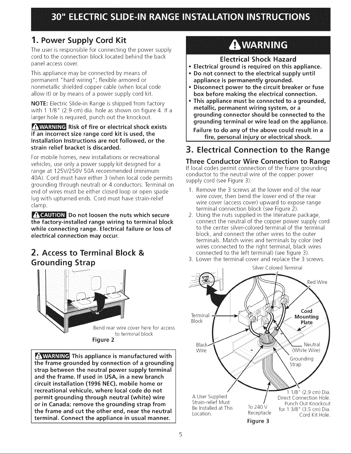
2. Access to Terminal Block &
Grounding Strap
Electrical Shock Hazard
o Electrical ground is required on this appliance,
Do not connect to the electrical supply until
appliance is permanently grounded.
Disconnect power to the circuit breaker or fuse
box before making the electrical connection,
This appliance must be connected to a grounded,
metallic, permanent wiring system, or a
grounding connector should be connected to the
grounding terminal or wire lead on the appliance,
Failure to do any of the above could result in a
fire, personal injury or electrical shock.
3. Electrical Connection to the Range
Three Conductor Wire Connection to Range
If local codes permit connection of the frame grounding
conductor to the neutral wire of the copper power
supply cord (see Figure 3):
1. Remove the 3 screws at the lower end of the rear
wire cover, then bend the lower end of the rear
wire cover (access cover) upward to expose range
terminal connection block (see Figure 2).
2. Using the nuts supplied in the literature package,
connect the neutral of the copper power supply cord
to the center silver-colored terminal of the terminal
block, and connect the other wires to the outer
terminals. Match wires and terminals by color (red
wires connected to the right terminal, black wires
connected to the left terminal) (see figure 3).
3. Lower the terminal cover and replace the 3 screws.
Silver Colored Terminal
Bend rear wire cover here for access
to terminal block
Figure 2
This appliance is manufactured with
the frame grounded by connection of a grounding
strap between the neutral power supply terminal
and the frame. If used in USA, in a new branch
circuit installation (1996 NEC), mobile home or
recreational vehicule, where local code do not
permit grounding through neutral (white) wire
or in Canada; remove the grounding strap from
the frame and cut the other end, near the neutral
terminal, Connect the appliance in usual manner,
Terminal
Block
Wire
A User Supplied
Strain-relief Must
Be Installed at This
Location.
To240 V
Receptacle
Figure 3
RedWire
1 1/8" (2.9 cm) Dia.
Direct Connection Hole.
Punch Out Knockout
for 1 3/8" (3.5 cm) Dia.
Cord Kit Hole.
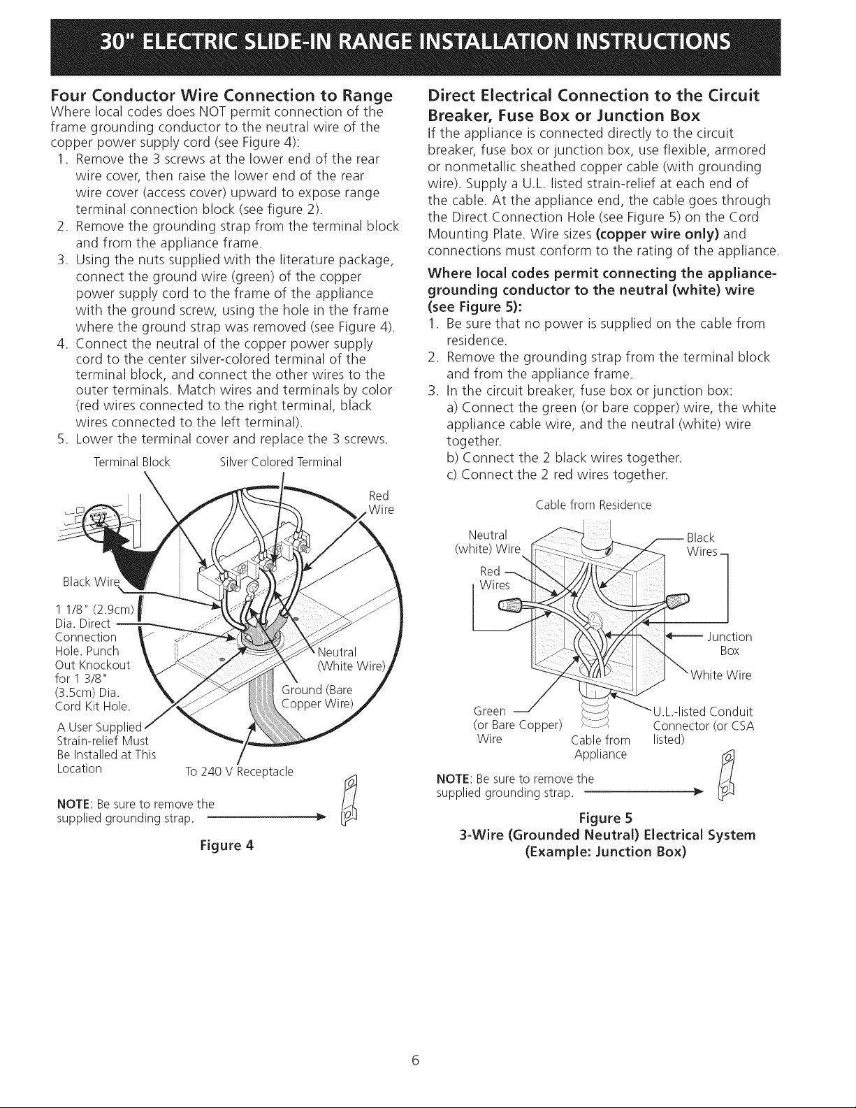
Four Conductor Wire Connection to Range
Where local codes does NOT permit connection of the
frame grounding conductor to the neutral wire of the
copper power supply cord (see Figure 4):
1. Remove the 3 screws at the lower end of the rear
wire cover, then raise the lower end of the rear
wire cover (access cover) upward to expose range
terminal connection block (see figure 2).
2. Remove the grounding strap from the terminal block
and from the appliance frame.
3. Using the nuts supplied with the literature package,
connect the ground wire (green) of the copper
power supply cord to the frame of the appliance
with the ground screw, using the hole in the frame
where the ground strap was removed (see Figure 4).
4. Connect the neutral of the copper power supply
cord to the center silver-colored terminal of the
terminal block, and connect the other wires to the
outer terminals. Match wires and terminals by color
(red wires connected to the right terminal, black
wires connected to the left terminal).
5. Lower the terminal cover and replace the 3 screws.
TerminalBlock SilverColoredTerminal
Red
.Wire
Direct Electrical Connection to the Circuit
Breaker, Fuse Box or Junction Box
If the appliance is connected directly to the circuit
breaker, fuse box or junction box, use flexible, armored
or nonmetallic sheathed copper cable (with grounding
wire). Supply a U.L. listed strain-relief at each end of
the cable. At the appliance end, the cable goes through
the Direct Connection Hole (see Figure 5) on the Cord
Mounting Plate. Wire sizes (copper wire only) and
connections must conform to the rating of the appliance.
Where local codes permit connecting the appliance-
grounding conductor to the neutral (white) wire
(see Figure 5):
1. Be sure that no power is supplied on the cable from
residence.
2. Remove the grounding strap from the terminal block
and from the appliance frame.
3. In the circuit breaker, fuse box or junction box:
a) Connect the green (or bare copper) wire, the white
appliance cable wire, and the neutral (white) wire
together.
b) Connect the 2 black wires together.
c) Connect the 2 red wires together.
Cable from Residence
BlackWire
1 1/8" (2.9cm) f
Dia. Direct
m
Connection
Hole.Punch
Out Knockout
for 13/8"
(3.5cm)Dia.
Cord Kit Hole.
A User Supplied
Strain-relief Must
Be Installed at This
Location
NOTE: Be sure to remove the
supplied grounding strap.
To 240 V Receptacle
Figure 4
NOTE: Be sure to remove the
supplied grounding strap.
Figure 5
3-Wire (Grounded Neutral) Electrical System
(Example: Junction Box)
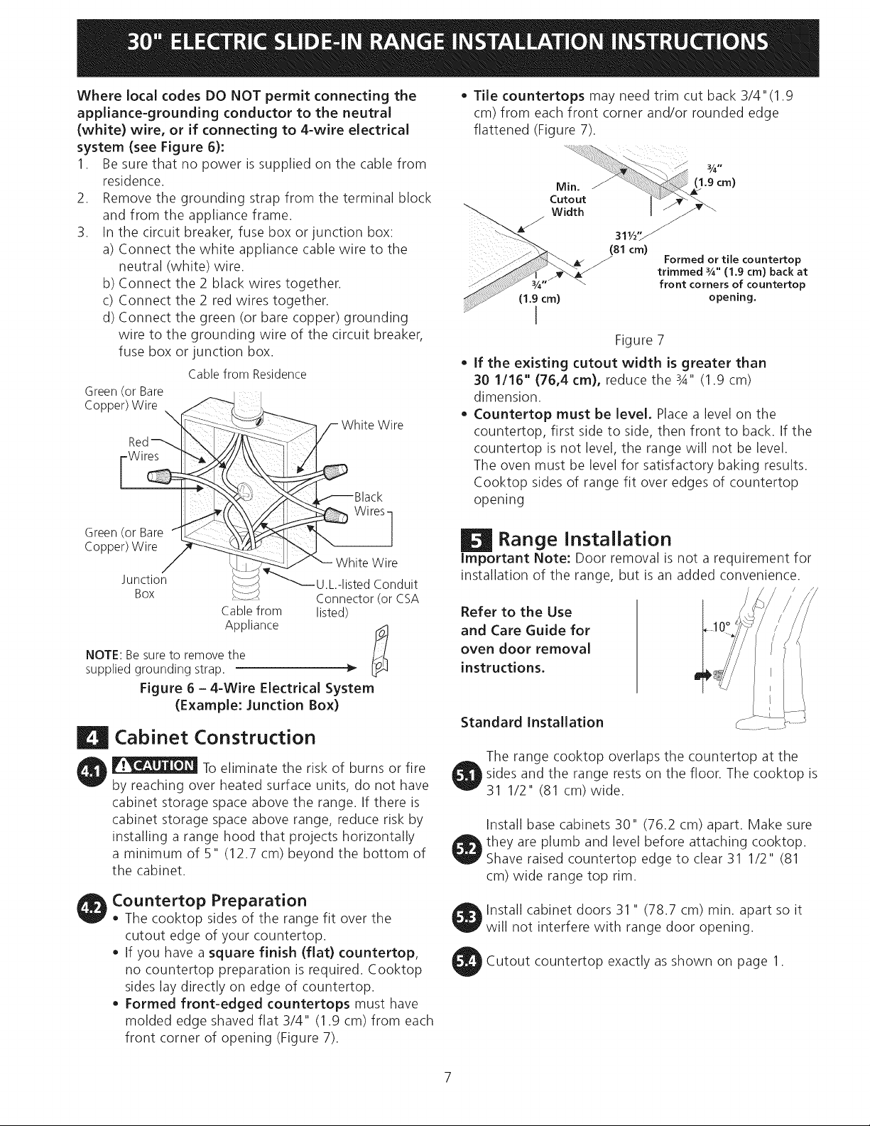
WherelocalcodesDONOTpermitconnectingthe
appliance-groundingconductorto theneutral
(white)wire, orif connectingto 4-wireelectrical
system(seeFigure6):
1. Besurethatnopowerissuppliedonthecablefrom
residence.
2. Removethegroundingstrapfromtheterminalblock
andfromtheapplianceframe.
3. Inthecircuitbreaker,fuseboxorjunctionbox:
a)Connectthewhiteappliancecablewiretothe
neutral(white)wire.
b)Connectthe2 blackwirestogether.
c)Connectthe2 redwirestogether.
d)Connectthegreen(orbarecopper)grounding
wiretothegroundingwireofthecircuitbreaker,
fuseboxorjunctionbox.
CablefromResidence
Green (or Bare
Red_ b\ [-_
Copper)Wire _
_ White Wire
_Black
• Tile countertops may need trim cut back 3/4"(1.9
cm) from each front corner and/or rounded edge
flattened (Figure 7).
31,/,, ...--_
(81 cm)
(1.9 cm) opening,
Formed or tile countertop
trimmed _A" (1,9 cm) back at
front corners of countertop
I
Figure 7
If the existing cutout width is greater than
30 1/16" (76,4 cm), reduce the 3A" (1.9 cm)
dimension.
Countertop must be level, Place a level on the
countertop, first side to side, then front to back. If the
countertop is not level, the range will not be level.
The oven must be level for satisfactory baking results.
Cooktop sides of range fit over edges of countertop
opening
Green(or Bare fL:_
Copper)Wire _
Junction _......
Box
Cablefrom
Appliance
NOTE: Be sure to remove the
supplied grounding strap.
Figure 6 - 4-Wire Electrical System
(Example: Junction Box)
Wires]
_,is T; uit
Connector(or CSA
listed)
Cabinet Construction
To eliminate the risk of burns or fire
by reaching over heated surface units, do not have
cabinet storage space above the range. If there is
cabinet storage space above range, reduce risk by
installing a range hood that projects horizontally
a minimum of 5" (12.7 cm) beyond the bottom of
the cabinet.
Countertop Preparation
• The cooktop sides of the range fit over the
cutout edge of your countertop.
• If you have a square finish (flat) countertop,
no countertop preparation is required. Cooktop
sides lay directly on edge of countertop.
• Formed front-edged countertops must have
molded edge shaved flat 3/4" (1.9 cm) from each
front corner of opening (Figure 7).
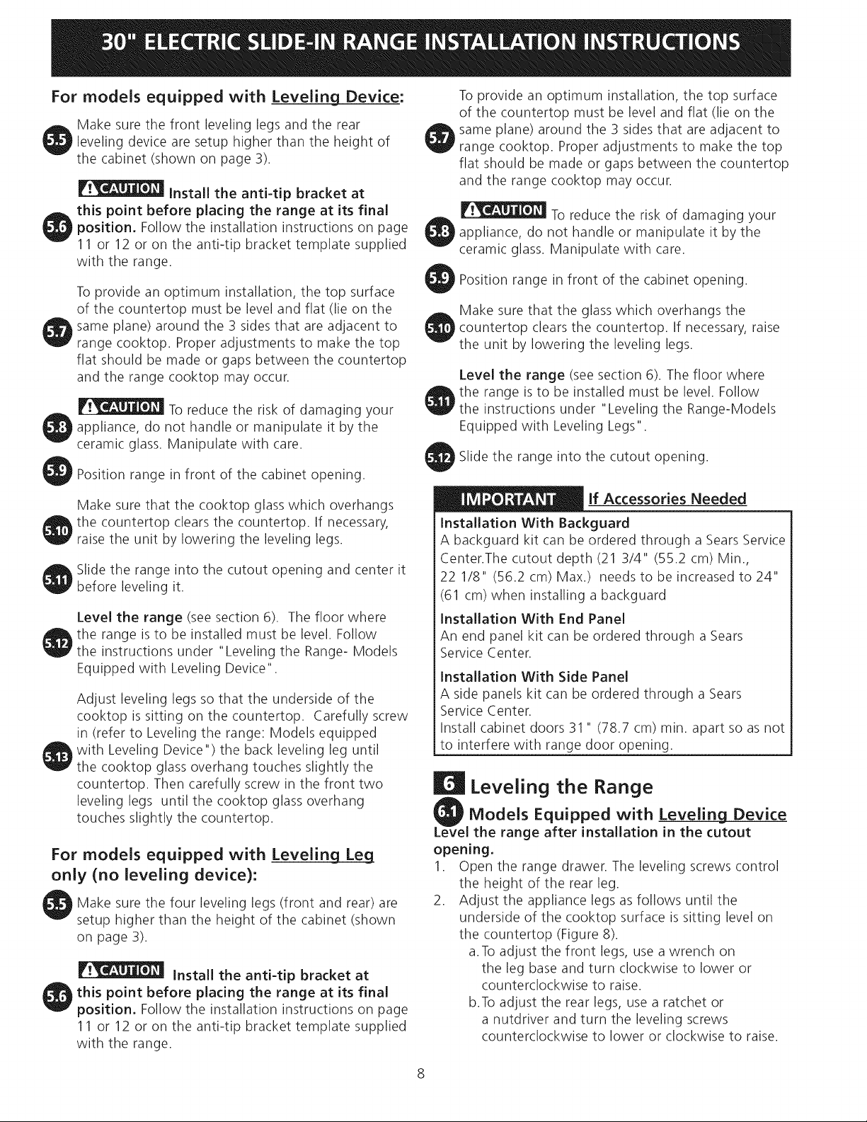
Range Installation
Important Note: Door removal is not a requirement for
installation of the range, but is an added convenience.
Refer to the Use
and Care Guide for
oven door removal
instructions.
Standard Installation
The range cooktop overlaps the countertop at the
sides and the range rests on the floor. The cooktop is
31 1/2" (81 cm)wide.
Install base cabinets 30" (76.2 cm) apart. Make sure
they are plumb and level before attaching cooktop.
Shave raised countertop edge to clear 31 1/2" (81
cm) wide range top rim.
Install cabinet doors 31 " (78.7 cm) min. apart so it
will not interfere with range door opening.
Cutout countertop exactly as shown on page 1.
7
For models equipped with Leveling Device:
Make sure the front leveling legs and the rear
leveling device are setup higher than the height of
the cabinet (shown on page 3).
install the anti-tip bracket at
this point before placing the range at its final
position. Follow the installation instructions on page
11 or 12 or on the anti-tip bracket template supplied
with the range.
To provide an optimum installation, the top surface
of the countertop must be level and flat (lie on the
same plane) around the 3 sides that are adjacent to
range cooktop. Proper adjustments to make the top
flat should be made or gaps between the countertop
and the range cooktop may occur.
To reduce the risk of damaging your
appliance, do not handle or manipulate it by the
ceramic glass. Manipulate with care.
Position range in front of the cabinet opening.
Make sure that the glass which overhangs the
countertop clears the countertop. If necessary, raise
the unit by lowering the leveling legs.
Level the range (see section 6). The floor where
O he range is to be installed must be level. Follow
the instructions under "Leveling the Range-Models
Equipped with Leveling Legs".
Slide the range into the cutout opening.
Make sure that the cooktop glass which overhangs
the countertop clears the countertop. If necessary,
raise the unit by lowering the leveling legs.
Slide the range into the cutout opening and center it
before leveling it.
Level the range (see section 6). The floor where
the range isto be installed must be level. Follow
the instructions under "Leveling the Range- Models
Equipped with Leveling Device".
Adjust leveling legs so that the underside of the
cooktop is sitting on the countertop. Carefully screw
in (refer to Leveling the range: Models equipped
with Leveling Device") the back leveling leg until
the cooktop glass overhang touches slightly the
countertop. Then carefully screw in the front two
leveling legs until the cooktop glass overhang
touches slightly the countertop.
For models equipped with Levelin Lg_L_e_g
only (no leveling device):
Make sure the four leveling legs (front and rear) are
setup higher than the height of the cabinet (shown
on page 3).
Install the anti-tip bracket at
this point before placing the range at its final
position. Follow the installation instructions on page
11 or 12 or on the anti-tip bracket template supplied
with the range.
lf Accessories Needed
Installation With Backguard
A backguard kit can be ordered through a Sears Service
Center.The cutout depth (21 3/4" (55.2 cm) Min.,
22 1/8" (56.2 cm) Max.) needs to be increased to 24"
(61 cm) when installing a backguard
installation With End Panel
An end panel kit can be ordered through a Sears
Service Center.
installation With Side Panel
A side panels kit can be ordered through a Sears
Service Center.
Install cabinet doors 31 " (78.7 cm) min. apart so as not
to interfere with range door opening.
Leveling the Range
Models Equipped with Leveling Device
the range after installation in the cutout
opening.
1. Open the range drawer. The leveling screws control
the height of the rear leg.
2. Adjust the appliance legs as follows until the
underside of the cooktop surface is sitting level on
the countertop (Figure 8).
a.To adjust the front legs, use a wrench on
the leg base and turn clockwise to lower or
counterclockwise to raise.
b.To adjust the rear legs, use a ratchet or
a nutdriver and turn the leveling screws
counterclockwise to lower or clockwise to raise.
 Loading...