


Kenmore 42732, 42733, 42739 Quick Start Manual
INSTALLATION AND SERVICE MUST BE PERFORMED BY A
QUALIFIED INSTALLER.
IMPORTANT: SAVE FOR LOCAL ELECTRICAL INSPECTOR'S USE.
READ AND SAVE THESE INSTRUCTIONS FOR FUTURE REFERENCE.
llr__FOR YOUR SAFETY: Do not store or use gasoline or other
iflammable vapors and liquids in the vicinity of this or any other appliance,
Canada
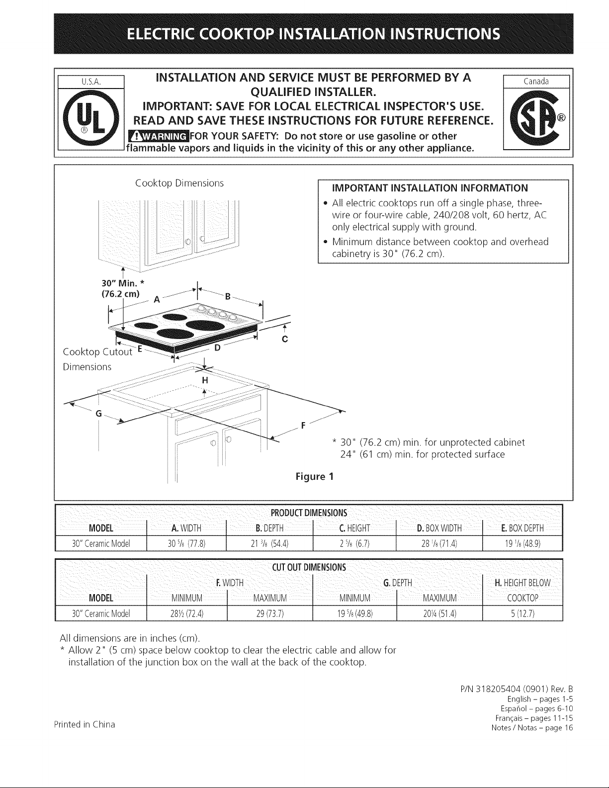
Cooktop Cutout
Dimensions
Cooktop Dimensions
IMPORTANT INSTALLATION INFORMATION
• All electric cooktops run off a single phase, three-
wire or four-wire cable, 240/208 volt, 60 hertz, AC
only electrical supply with ground.
• Minimum distance between cooktop and overhead
cabinetry is 30" (76.2 cm).
C
* 30" (76.2 cm) min. for unprotected cabinet
24" (61 cm) min. for protected surface
Figure 1
MODEL A:WIDTH B.DEPTH CHEIGHT D.BOXWtDTH E.BOXDEPTH
30"CeramicModel 30s/8(77.8) 213/8(54,4) 2%(6.7) 28V8(71.4) I9_/8(48,9)
30"CeramicModel 28Y_(72.4) 29(73.7) 195/8(49.8) 20_A(51,4) 5(12.7)
All dimensions are in inches (cm).
* Allow 2" (5 cm) space below cooktop to clear the electric cable and allow for
installation of the junction box on the wall at the back of the cooktop.
P/N 318205404 (0901) Rev. B
Espahol- pages 6-10
Printed in China
Fran_ais- pages 11-15
Notes / Notas - page 16
English - pages 1-5
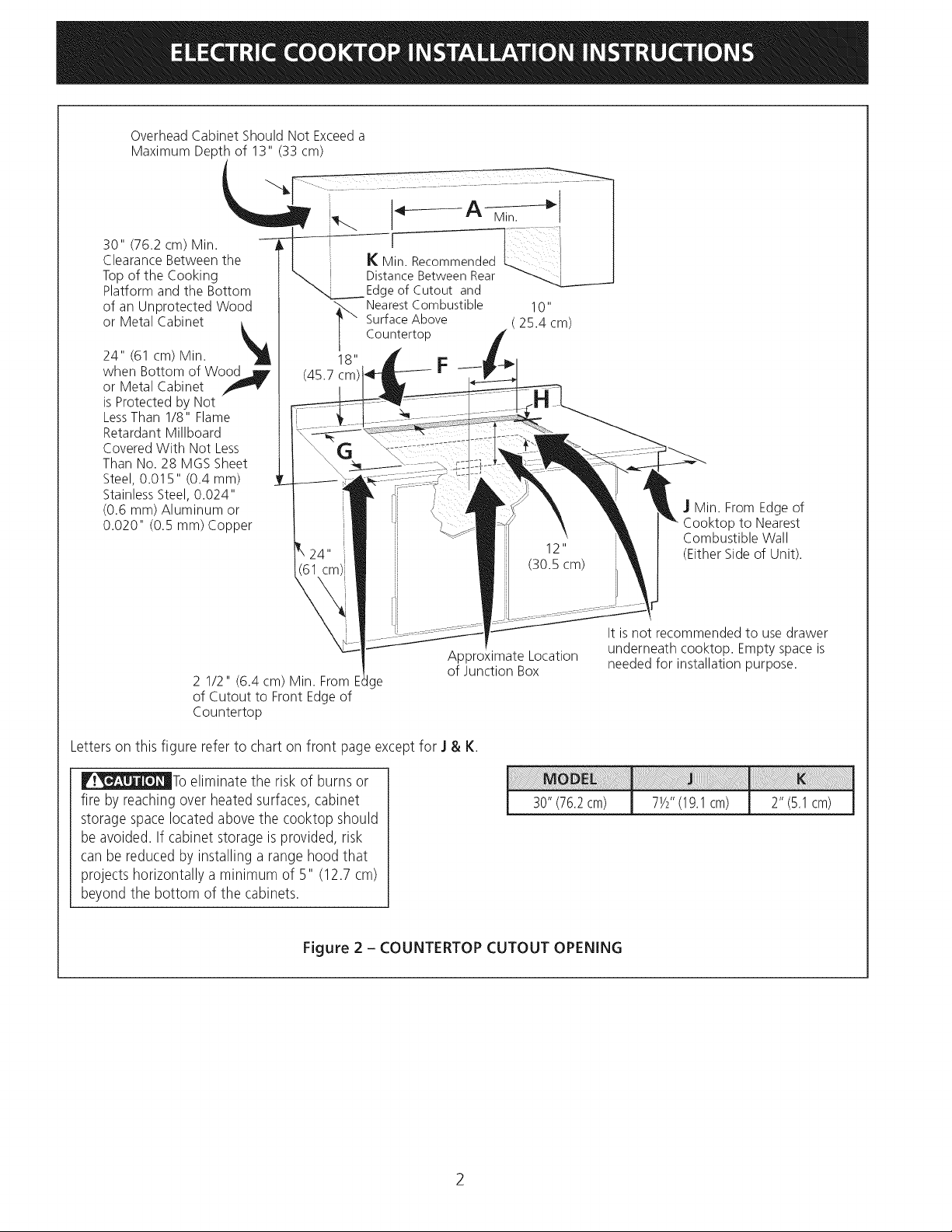
Overhead Cabinet Should Not Exceeda
Maximum Depth of 13" (33 cm)
30" (76.2 cm) Min.
Clearance Between the
Top of the Cooking
Platform and the Bottom
of an Unprotected Wood
or Metal Cabinet
24" (61 cm) Min.
when Bottom of Wood jF
or Metal Cabinet
is Protected by Not
LessThan 1/8" Flame
Retardant Millboard
Covered With Not Less
Than No. 28 MGS Sheet
Steel, 0.015" (0.4 mm)
Stainless Steel, 0.024"
(0.6 ram) Aluminum or
0.020" (0.5 mm) Copper
18" F
(45.7 cm)
I(Min. Recommended I
Distance Between Rear
Edgeof Cutout and
SurfaceAbove ( 25.4 cm)
Nearest Combustible 10"
Countertop
] Min. From Edge of
,p to Nearest
Combustible Wall
(Either Side of Unit).
Approximate Location
of Junction Box
2 1/2" (6.4 cm) Min. From E ge
of Cutout to Front Edge of
Countertop
Letterson this figure refer to chart on front page exceptfor ] & K.
_To eliminate the riskof burns or
fire by reachingover heated surfaces,cabinet
storage spacelocated above the cooktop should
be avoided. If cabinet storage is provided, risk
canbe reduced by installing a range hood that
projectshorizontally a minimum of 5" (12.7 cm)
beyond the bottom of the cabinets.
Figure 2 - COUNTERTOP CUTOUT OPENING
It is not recommended to use drawer
underneath cooktop. Empty space is
needed for installation purpose.
30"(76.2cm) 7½"(19.1cm) 2"(5.1cm)
2
Important Notes to the Installer
1. Read all instructions contained in these installation
instructions before installing the appliance.
2. Remove all packing material before connecting the
electrical supply to the appliance.
3. Observe all governing codes and ordinances.
4. Be sure to leave these instructions with the consumer.
Important Note to the Consumer
Keep these instructions with your Owner's Guide for the
local electrical inspector's use and future reference.
IMPORTANT SAFETY
INSTRUCTIONS
• Be sure your appliance is installed and grounded
properly by a qualified installer or service
technician.
• These appliances must be electrically grounded in
accordance with local codes or, in their absence,
with the National Electrical Code CSA Standard
C22.1, Canadian Electrical Code, Part 1, in Canada.
NOTE: Wire sizes and connections must conform with
the fuse size and rating of the appliance in accordance
with the American National Electrical Code ANSI/NFPA
No. 70-latest edition, or with Canadian CSA Standard
C22.1, Canadian Electrical Code, Part 1, and local codes
and ordinances.
An extension cord should not be used
with this appliance. Such use may result in a fire,
electrical shock, or other personal injury.
2. The flexible armored cable extending from the
appliance should be connected directly to the
junction box. The junction box should be located as
shown in Figure 1 or Figure 2 and with as much slack
as possible remaining in the cable between the box
and the appliance, so it can be moved if servicing is
ever necessary.
3. A suitable strain relief must be provided to attach
the flexible armored cable to the junction box.
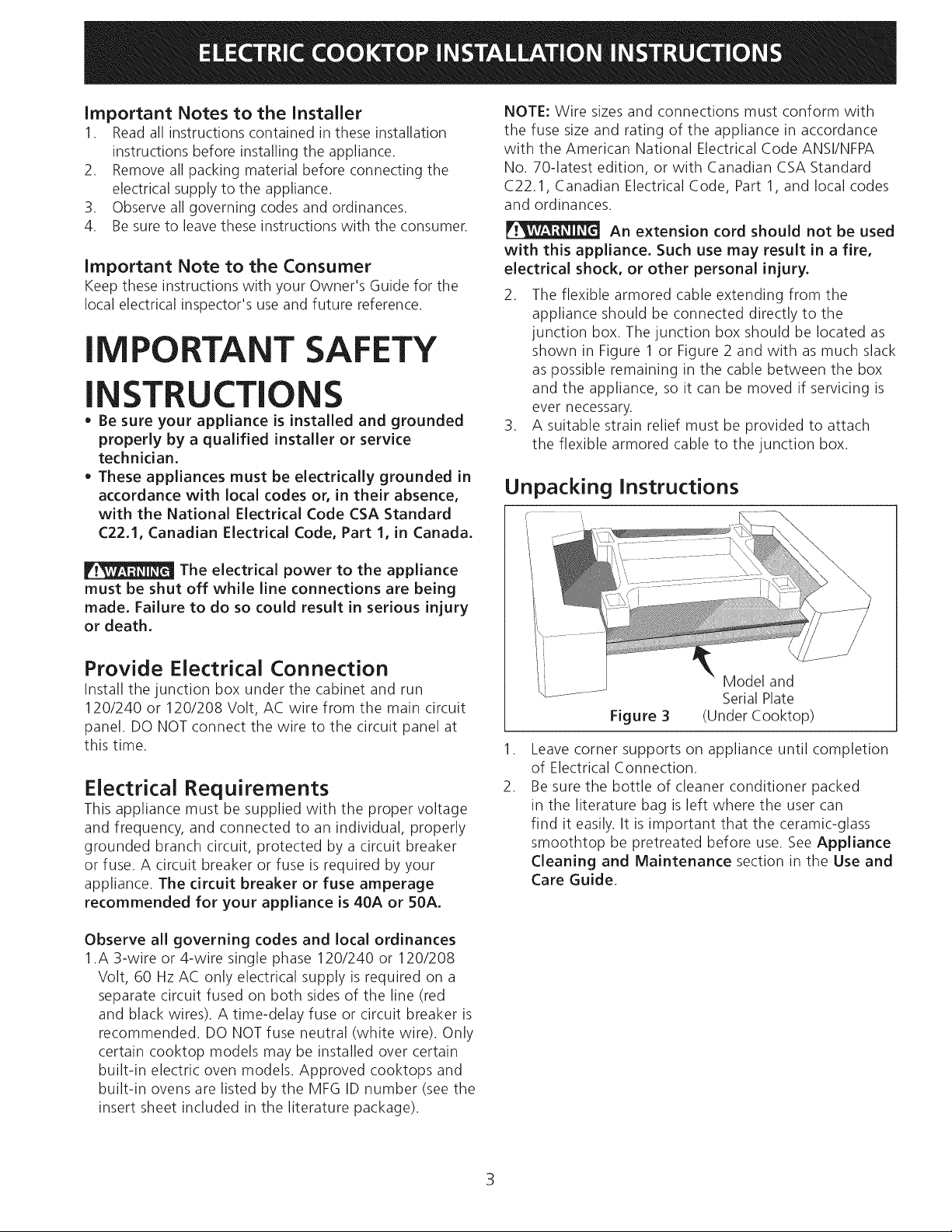
Unpacking Instructions
The electrical power to the appliance
must be shut off while line connections are being
made. Failure to do so could result in serious injury
or death.
Provide Electrical Connection
Install the junction box under the cabinet and run
120/240 or 120/208 Volt, AC wire from the main circuit
panel. DO NOT connect the wire to the circuit panel at
this time.
Electrical Requirements
This appliance must be supplied with the proper voltage
and frequency, and connected to an individual, properly
grounded branch circuit, protected by a circuit breaker
or fuse. A circuit breaker or fuse is required by your
appliance. The circuit breaker or fuse amperage
recommended for your appliance is 40A or 50A,
Observe all governing codes and local ordinances
1.A 3-wire or 4-wire single phase 120/240 or 120/208
Volt, 60 Hz AC only electrical supply is required on a
separate circuit fused on both sides of the line (red
and black wires). A time-delay fuse or circuit breaker is
recommended. DO NOT fuse neutral (white wire). Only
certain cooktop models may be installed over certain
built-in electric oven models. Approved cooktops and
built-in ovens are listed by the MFG ID number (see the
insert sheet included in the literature package).
Model and
Serial Plate
Figure 3
,
Leave corner supports on appliance until completion
of Electrical Connection.
2.
Be sure the bottle of cleaner conditioner packed
in the literature bag is left where the user can
find it easily. It is important that the ceramic-glass
smoothtop be pretreated before use. See Appliance
Cleaning and Maintenance section in the Use and
Care Guide.
(Under Cooktop)
3
Electrical Connection
Connect the flexible armored cable that extends from the
surface unit to the junction box using a suitable strain
relief at the point the armored cable enters the junction
box. Then make the electrical connection asfollows.
Improper connection of aluminum
house wiring to copper leads can result in a short
circuit or fire. Follow the connector manufacturer
recommended procedure closely.
This appliance is equipped with a
copper conductor flexible cable. If connection
is made to aluminum house wiring, use only
special connectors which are approved for joining
copper and aluminum wires in accordance with
the National Electrical Code and local codes and
ordinances.
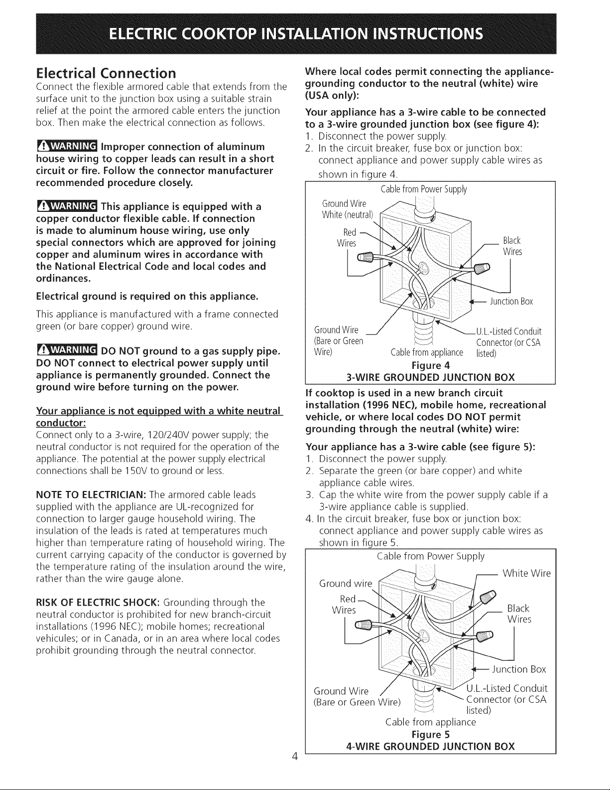
Where local codes permit connecting the appliance-
grounding conductor to the neutral (white) wire
(USA only):
Your appliance has a 3-wire cable to be connected
to a 3-wire grounded junction box (see figure 4):
1. Disconnect the power supply.
2. In the circuit breaker, fuse box or junction box:
connect appliance and power supply cable wires as
shown in figure 4.
CablefromPowerSupply
GroundWire
White(neutral)
Red
Wires
Black
Wires
Electrical ground is required on this appliance.
This appliance is manufactured with a frame connected
green (or bare copper) ground wire.
DO NOT ground to a gas supply pipe.
DO NOT connect to electrical power supply until
appliance is permanently grounded. Connect the
ground wire before turning on the power.
Your appliance is not equipped with a white neutral
conductor:
Connect only to a 3-wire, 120/240V power supply; the
neutral conductor is not required for the operation of the
appliance. The potential at the power supply electrical
connections shall be 150V to ground or less.
NOTE TO ELECTRICIAN: The armored cable leads
supplied with the appliance are UL-recognized for
connection to larger gauge household wiring. The
insulation of the leads is rated at temperatures much
higher than temperature rating of household wiring. The
current carrying capacity of the conductor is governed by
the temperature rating of the insulation around the wire,
rather than the wire gauge alone.
JunctionBox
GroundWire U.L.-ListedConduit
(Bareor Green Connector(orCSA
Wire) Cablefromappliance listed)
Figure 4
3-WIRE GROUNDED JUNCTION BOX
If cooktop is used in a new branch circuit
installation (1996 NEC), mobile home, recreational
vehicle, or where local codes DO NOT permit
grounding through the neutral (white) wire:
Your appliance has a 3-wire cable (see figure 5):
1. Disconnect the power supply.
2. Separate the green (or bare copper) and white
appliance cable wires.
3. Cap the white wire from the power supply cable if a
3-wire appliance cable is supplied.
4. In the circuit breaker, fuse box or junction box:
connect appliance and power supply cable wires as
shown in figure 5.
Cable from Power Supply
-- White Wire
RISK OF ELECTRIC SHOCK: Grounding through the
neutral conductor is prohibited for new branch-circuit
installations (1996 NEC); mobile homes; recreational
vehicules; or in Canada, or in an area where local codes
prohibit grounding through the neutral connector.
Red
Wires :
- ioo ox
(Ground GVVI_enWire) _ U_n-L;sctt°drfOnCd_
_-J listed)
Cable from appliance
Figure 5
4-WIRE GROUNDED JUNCTION BOX
4
Cooktop Installation
1. Visually inspect the cooktop for damage. Also make
sure all cooktop screws are tight (see Figure 8).
Screws
Figure 8
2. Install the retainer brackets. See Figure 9
The retainer brackets MUST be installed, to meet
local codes or, in their absence, with the National
Electrical Code CSA Standard C22.1, Canadian
Electrical Code, Part I (see Figure 9).
Cooktop,_
Built-in
spring
Countertop
Retainer Brackets Must
t Be Installed At Least
1/16" (0.16 cm) BELOW
Countertop
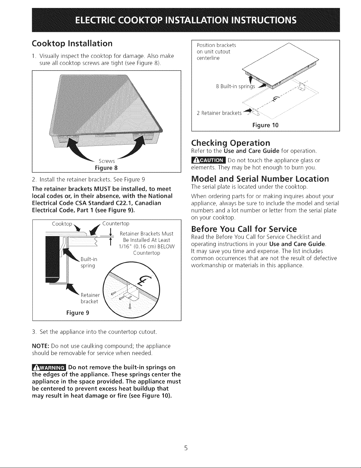
Position brackets
on unit cutout
centerline
Figure 10
Checking Operation
Refer to the Use and Care Guide for operation
Do not touch the appliance glass or
elements. They may be hot enough to burn you.
Model and Serial Number Location
The serial plate is located under the cooktop.
When ordering parts for or making inquires about your
appliance, always be sure to include the model and serial
numbers and a lot number or letter from the serial plate
on your cooktop.
Before You Call for Service
Read the Before You Call for Service Checklist and
operating instructions in your Use and Care Guide.
It may save you time and expense. The list includes
common occurrences that are not the result of defective
workmanship or materials in this appliance.
Retainer
bracket
Figure 9
3. Set the appliance into the countertop cutout.
NOTE: Do not use caulking compound; the appliance
should be removable for service when needed.
Do not remove the built-in springs on
the edges of the appliance. These springs center the
appliance in the space provided. The appliance must
be centered to prevent excess heat buildup that
may result in heat damage or fire (see Figure 10).
 Loading...