


Kenmore 153 327566, 153.327365, 153.327366, 153.327665, 153.327666 Owner's Manual
...
Owner's
Manual
FOR POTABLEWATER
HEATING ONLY
NOT SUITABLEFOR
SPACEHEATING
Hodel No.
153o327165_' 30 GaT, Short
153327166 30 Gai Short
153327265 40 Ga! Short
153,327266_J 40 Gai Short
153,327365 30 Gat,
153327366 30 Ga{,
153327465 40 GaL
153.327466 40 GaL
153.327565 50 Gal
153 327566 50 GaE
153 327665 66 Gal
153.327666 66 Gal,
153327865 80 GaL
153.327866 80 Gal.
Caution:
Read and Follow
All Safety Rules and
Operadng Instructions
Before First Use of
This Product°
_ve this Ma.nua| for Future Reference.
POWER MmSER TM 9
ELECTRIC
WATER NEA ER
o Safety Instructions
, installation
• Operation
- Care and Maintenance
o Troubleshooting
° Parts List
GAMA certification applies to all residential electric water heaters with
capacities of 20 to 120 Gatlons. Input rating of 12 Kw or less at a voltage
no greater than 250 _Z,
_.VVARNING
READ THE GENERAL SAFETY SECTION BEGINNING ON INSIDE COVER
AND THEN THIS ENTIRE MANUAL BEFORE INSTALLING OR OPERAT-
ING THIS WATER HEATER.
Sears, Roebuck and Co., Hoffman Estates, IL 60179 U.S.A.

Safety Precautions
_WARNING ]
Improper installation, adjustment, alteration, service or|
maintenance can cause DEATH, SERIOUS BODILY INJURY,,|
OR PROPERTY DAMAGE. Refer to this manual for assis-_
tance or consult your local Sears Service Center for further_
Linformat on, |
AWARNING
At the time of manufacture this water heater wasprovidedwith
a combination temperature-pressures relief valve certified by a
nationally recognized testing laboratory that maintains periodic
inspection of production of listed equipment or materials, as
meeting the requirements for Relief Valves and Automatic Gas
Shutoff Devices for Hot Water Supply Systems,and the current
edition of ANSI Z21.22 and the code requirements of ASME. If
replaced, the valve must meet the requirements of local codes,
but not lessthan a combination temperature and pressurerelief
valve certified asmeeting the requirements for Relief Valvesand
Automatic Gas Shutoff Devices for Hot Water Supply Systems,
ANSI Z2L22 by a nationally recognized testing laboratory that
maintains periodic inspection of production of listed equipment
or materials.
The valve must be mad_ed with a maximum set pressure not
to exceed the marked hydrostatic working pressure of the
water heater (150 Ibsop.s.L) and a discharge capacity not less
than the water heater input rate as shown on the model rat-
ing plate. (Electric heaters - watts divided by 1000 x 3412
equal BTUtHr. rate.)
Your local jurisdictionalauthority, while mandating the useof a
temperature-pressure relief valve complying with ANSI Z21.22
and ASME, may require a valvemodel different from the onefur-
nishedwith the water heater
Compliance with such local requirements must be satisfiedby
the installer or end user of the water heater with a locally pre-
scribed temperature-pressure relief valve installed in the desig-
nated opening in the water heater in place of the factory fur-
nishedvalve.
For safeoperation of the water heater, the relief valve must not
be removed from it'sdesignatedopeningor plugged.
The temperature-pressure relief valvemust be installed directly
into the fitting of the water heater designatedfor the reliefvalveo
Positionthe valve downward and provide tubing so that any dis-
charge will exit only within 6 inches above, or at any distance
below the structural floor. Be certain that no contact ismade
with any I;veelectrical part. The dischargeopening must not be
blocked or reduced in size under any circumstances. Excessive
length, over 30 feet, or use of more than four elbows can cause
restriction andreduce the dischargecapacityofthe valve.
No valve or other obstruction isto be placed between the relief
valve and the tank. Do not connect tubing directly to discharge
drain unlessa 6" air gap isprovided.To prevent bodily injury,haz-
ard to life, or property damage, the relief valve must be allowed
to dischargewater in quantiEesshouldcircumstancesdemand. If
the dischargepipe is not connectedto a drain or other suitable
means,the water flow m_y causeproperty damage.
The Discharge Pipe:
Must not be smaller in size than the outlet pipe size of the
valve, or have any reducing couplingsor other res_ctionso
Must not beplugged or blocked.
Must be of material listed for hot water distribution_
Must be installed so as to allow complete drainage of both
the temperature.pressure relief valve, and the discharge
pipe.
Must terminate at an adequate draln_
Must not have any valve between the relief valve and tank.
I AWARNING
HAZARD OF ELECTRICAL SHOCK! Before removing any
access panels or servicing the water heater_ make sure the
electrical supply to the water heater is turned "OFF"° Failure
to do this could result in DEATH, SERIOUS BODILY INJURY,
I OR PROPERTY DAMAGE.
AWARNING
HOTTER WATER CAN SCALD" Water heaters are intended
to produce hot water. Water heated to a temperature which
will satisfy space heating, clothes washing, dish washing_and
other sanitizing needs can scald and permanently injure you
upon contact. Some people are more likely to be permanently
injured by hot water than others. These include the elderly,
children, the infirm, or physically/mentally handicapped, tf
anyone using hot water in your home fits into one of these
groups or if there is a local code or state law requiring a cer=
lain temperature water at the hot water tap, then you must
take special precautions, In addition to using the lowest possi-
ble temperature setting that satisfiesyour hot water needs, a
means such as a mixing valve, shall be used at the hot water
taps used by these peopte or at the water heater_ Mixing
valves are available at plumbing supply or hardware stores,
Follow manufacturers instructions for installation of the
valves,Before changing the factory setting on the thermostat,
read the "Temperature Regulation" section in this manual.
_WARNING
WATER HEATERS EQUIPPED FOR ONE VOLTAGE ONKY:
This water heater is equipped for one type voltage only.
Check the rating plate near the bottom accesspanel for the
correct voltage. DO NOT use this water heater with any volt-
age other than the one shown on the model rating plate.
Failure to use the correct voltage can cause problems which
can result in DEATH, SERIOUS BODILY INJURY, OR PROP-
ERTY DAMAGE. If you have any questions or doubts consult
your electric company.
AWARNING
INSULATING JACKETS; When installing an external water
heater insulation jacket on an electric water heater:
a_DO NOT cover the temperature-pressure relief valve.
b0DO NOT put insulation over the access covers or any
access areas.
c. DO NOT cover or remove operating instructions, and safe-
ty related warning labels and materials affixed to the water
heater.
AWARNING
Do not use this appliance if any part of it has been under
water_ An electrical short or malfunction could occur. The
water heater should be replaced_
•_ CAUTION
WATER HEATERS EVENTUALLY LEAK: Installation of the
water heater must be accomplished in such a manner that if
the tank or any connections should leak, the flow of water
will not cause damage to the structure° For this reason, it is
not advisable to install the water heater in an attic or upper
floor. When such locations cannot be avoided, a suitable
drain pan should he installed under the water heater. Drain
pans are available at your local Sears Store. Such a drain pan
must be piped to an adequate drain° Under no circumstances
is the manufacturer or Sears to be held liable for any water
damage in connection with this water heater°
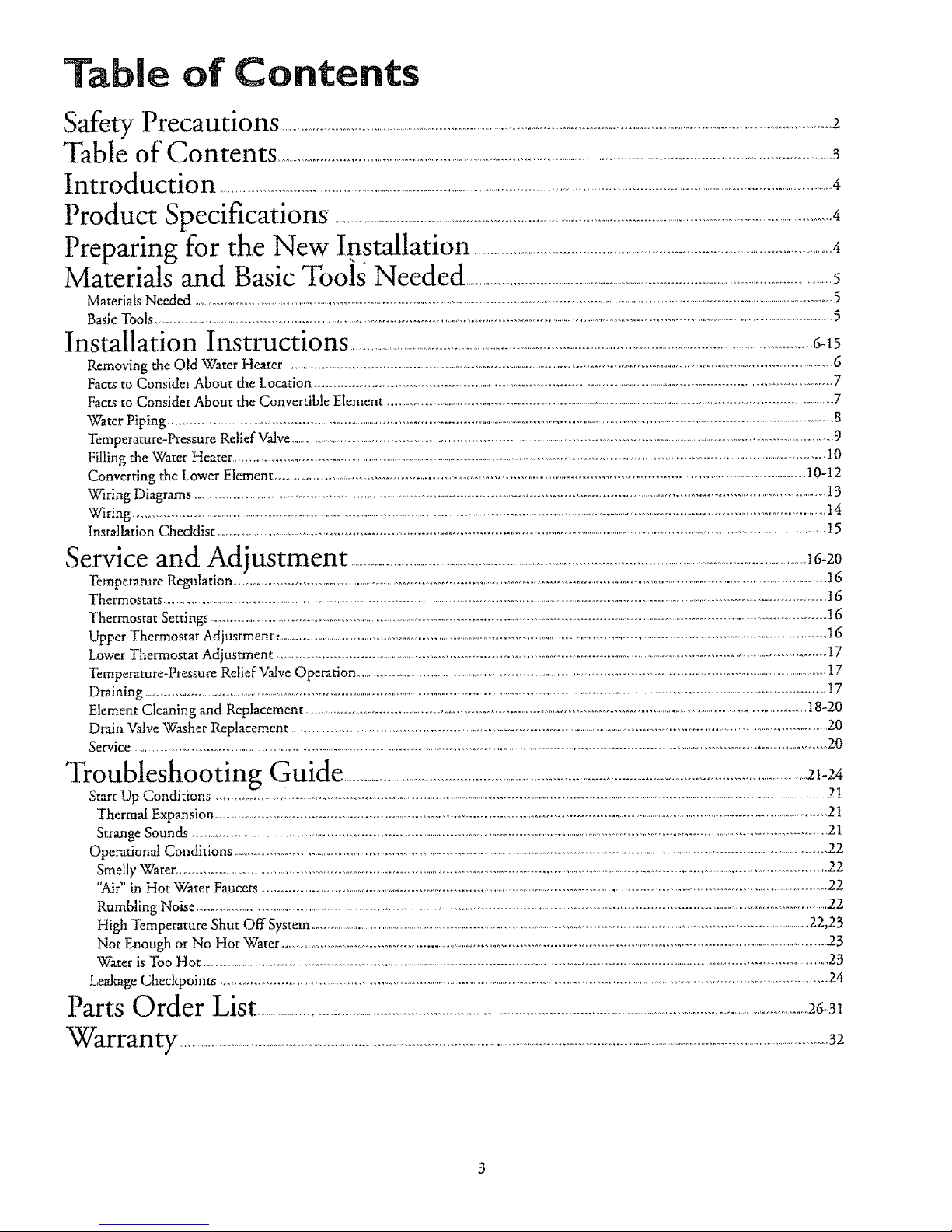
Table of Contents
Safety Precautions ......................................................................................................................2
Table of Contents ....................................................................................................................................................................................................3
Introduction ............................................................................................................................................................................................................................4
Product Specifications ......................................................................................................................................................................................4
" " 4
Preparing for the New Installanon ................................................................................................................................
Materials and Basic ,ToolsNeeded ...............................................................................................................................5
MateriOs Needed ............................................................................................................................................................................................................................................5
Basic Tools .................................................................................................................................................................................................................................5
Installation Instructions ...............................................................................................................................................................6.15
Removing the Old Water Heater .....................................................................................................................................................................................................6
Facts to Consider About the Location .................................................................................................................................................................................7
Facts to Consider About the Convertible Element ....................................................................................................................................................................7
Water Piping ..........................................................................................................................................................................................................................................8
Temperature-Pressure Relief Valve ........................................................................................................................................................................................9
Filling the Water Heater ............................................................................................................................................................................................................10
Converting the Lower Element ...............................................................................................................................................................................10-12
Wiring Diagrams ........................................................ 13
Wiring .....................................................................................................................................................................................................................................................t4
Installation Checldist ................................................................................................................................................................................................t5
Service and Adjustment .............................................................................................................,6-20
Temperature Regulation .....................................................................................................................................................................................................16
Thermostats ................................................................................................................................................................................................................................................16
Thermostat Settings ........................................................................................................................................................................................................................16
Upper Thermostat Adjustment: .....................................................................................................................................................................................................16
Lower Thermostat Adjustment .......................................................................................................................................................................................I7
Temperature-Pressure Relief Valve Operation ..........................................................................................................................................................................17
Draining .......................................................................................................................................................................................................17
Element Cleaning and Replacement ............................................................................................................................... 18-20
Drain Valve Washer Replacement ................................................................................... 20
Service ................................................................... 20
Troubleshooting Guide ...........................................................................................................................................................21-24
Start Up Conditions ?1
Thermal Expansion .......................................................................................................................................................................................................21
Strange Sounds ................................................................................................................................................................................................................................21
Operationa! Conditions ............................................................................................................................................................................................................22
Smelly Water .......................................................................................................................................................................................................................22
"Air" in Hot Water Faucets ......................................................................................................................................... 22
Rumbling Noise ..................................................................................................................................................................................................................22
High Temperature Shut Off System ................................................................................................................................................................................22,23
Not Enough or No Hot Water ..........................................................................................................................................................................................23
Water is Too Hot ..................................................................................................................................................................................................................23
Leakage Checkpoints ...........................................................................................................................................................................................24
Parts Order List........................:.................................................................................................................................................................26-31
Warranty ..........................................................................................................................................................................................................................32
|ntroduction
Thank You for purchasing a Seats water heater.
Properly installed and maintained, it should give you years of
trouble free service° If you should decide that you want the new
water heater professionally installed, contact the local Sears
Service Center or any Sears store. They wilt arrange for prompt,
quality installation by Sears authorized contractors.
Abbreviations Found In This Instruction Manual
UL-Underwriters Laboratories, 333 Pfingsten Rd. Northbrook,
IL60062
National Electrical Code-This publication is available from your
local government or public library or electric company or by
writing to UL.above.
ANSI-American National Standards Institute
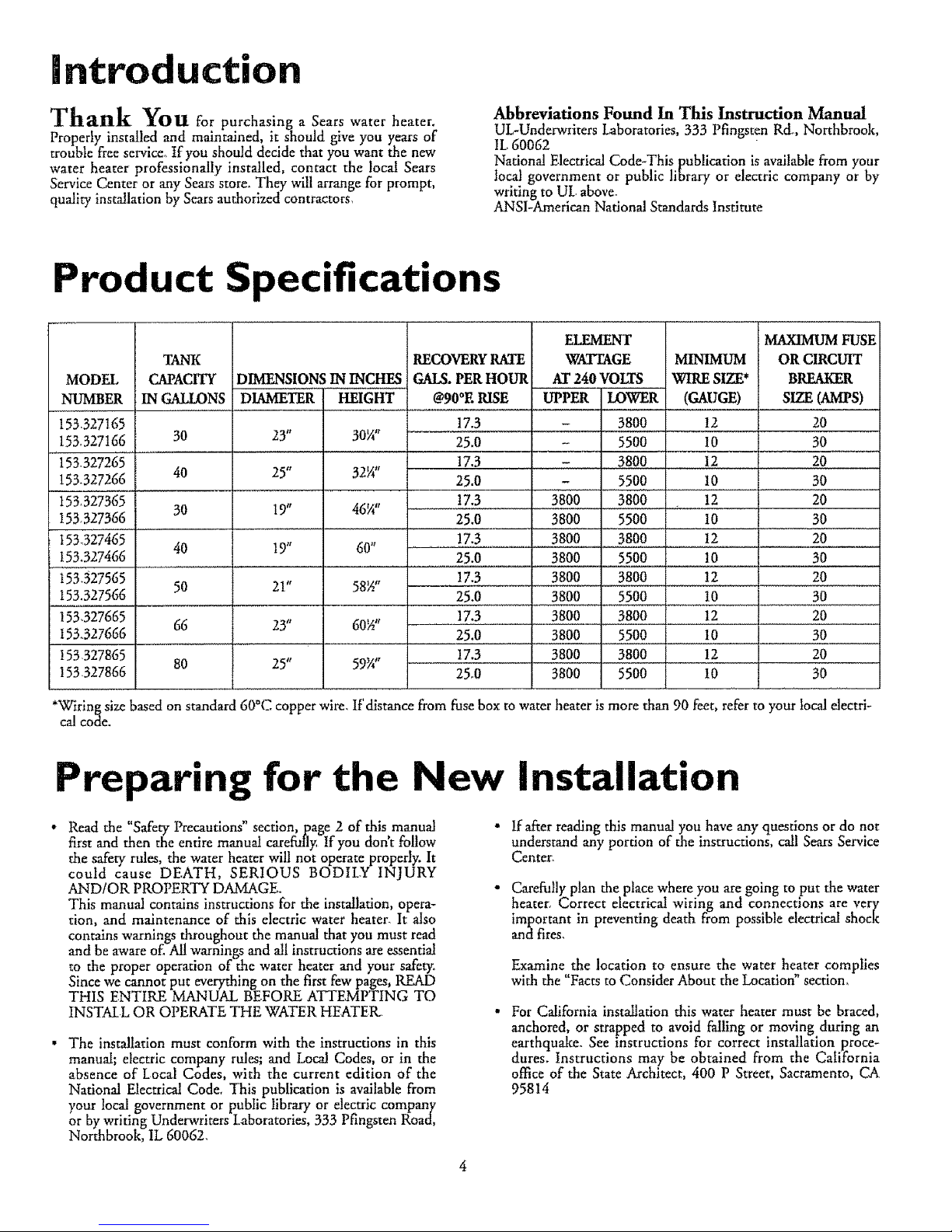
Product Specifications
MODEL
NUMBER
153,327165
153,327166
153,327265
153.327266
t53,327365
153,327366
t53.327465
153.327466
153.327565
153.327566
153',327665
I53,,327666
153327865
153327866
TANK
CAPACITY
IN GALLONS
30
40
30
40
50
66
80
DIMENSIONS ININCHES
DIAMETER HEIGHT
23" 30¼"
25° 32¼"
I9" 46¼"
19" 60"
21" 58_"
23" 60_"
25" 59_"
RECOVERYRATE
GALS. PER HOUR
@90°E RISE
17.3
25,0
17,3
25.0
t7.3
25.0
ELEMHWF
WATTAGE
AT 240 VOLTS
UPPER LOWER
- 3800
- 5500
- 3800
- 5500
MINIMUM
WIRE SIZE*
(GAUGE)
12
I0
I2
10
MAXIMUM FUSE
OR CIRCUIT
BREAKER
SIZE (AMI'S)
20
30
20
30
3800 3800 : 12 20
3800 5500 t0 30
!7.3 . 3800 . 3800 , 12 . 20
25.0 3800 5500 10 30
!7.3 3800 3800 12 20
25.0 3800 5500 t0 30
17.3 . 3800 . 3800 . 12 . 20
25.0 3800 5500 10 30
17.3 3800 3800 12 20
25.0 3800 5500 t0 30
*Wiring size based on standard 60°C copper wire. If distance from fuse box m water heater is more than 90 feet, refer to your local electri-
ca! code.
.ring for the New installation
Read the "Safety Precautions" section, page 2 of this manual •
first and then the entire manual carefully If you don't follow
the safety rules, the water heater will not operate properly. It
could cause DEATH, SERIOUS BODILY INJURY
AND/OR PROPERTY DAMAGE. "
This manual contains instructions for the installation, opera-
tion, and maintenance of this electric water heater. It also
contains warnings throughout the manual that you must read
and be aware of. All warnings and all instructions are essential
to the proper operation of the water heater and your safety.
Since we cannot put everything on the first few pages, READ
THIS ENTIRE MANUAL BEFORE ATFEMPTtNG TO
INSTALL OR OPERATE THE WATER HEATER
The installation must conform with the instructions in this
manual; electric company rules; and Local Codes, or in the
absence of Local Codes, with the current edition of the
National Electrical Code, This publication is available from
your local government or public library or electric company
or by writing Underwriters Laboratories, 333 Pfingsten Road,
Northbrook, IL 60062.
If after reading this manual you have any questions or do not
understand any portion of the instructions, call Sears Service
Center.
Carefully plan the place where you are going to put the water
heater. Correct electrical wiring and connections are very
important in preventing death from possible electrical shock
and fires,
Examine the location to ensure the water heater complies
with the "Facts to Consider About the Locatioff' section,
For California installation this water heater must be braced,
anchored, or strapped to avoid falling or moving during an
earthquake. See instructions for correct installation proce-
dures. Instructions may be obtained from the California
office of the State Architect, 400 P Street, Sacramento, CA
95814
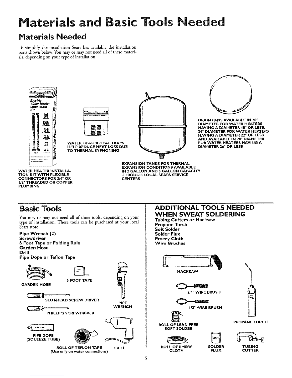
Materials an Basic
Materials Needed
To simplifit the installation Sears has available the inst£Iation
parts shown below You may or may not need all of these materi-
als, depending on your type of installation
Tools
eeded
WATER HEATER INSTALLA.
TION KIT WITH FLEXIBLE
CONNECTORS FOR 3f4" OR
1/2" THREADED OR COPPER
PLUHBING
r.......
WATER HEATER HEAT TRAPS
HELP REDUCE HEAT LOSS DUE
TO THERHAL SYPHONING
EXPANSION TANKS FOR THERHAL
EXPANSION CONDITIONS AVAILABLE
IN 2 GALLON AND 5 GALLON CAPACITY
THROUGH LOCAL SEARS SERVICE
CENTERS
DRAIN PANS AVAILABLE IN 20"
DIAHETER FOR WATER HEATERS
HAVING A DIAMETER 18" OR LESS,
24" DIAHETER FOR WATER HEATERS
HAVING A DIAMETER 22" OR LESS
AND AVAILABLE IN 28" DIAHETER
FOR WATER HEATERS HAVING A
DIAHETER 7.6" OR LESS
szSiCTools
You may or may not need all of these tools, depending on your
type of installation, These tools can be purchased at your !ocal
SL_I[_ store°
Pipe Wrench (2)
Screwdriver
6 Foot Tape or Folding Rulo
Garden Hose
Drill
Pipe Dope or Teflon Tape
6 FOOT TAPE
GARDEN HOSE
SLOT-HEAD SCREW DRIVER
PHILLIPS SCREWDRIVER
PIPE DOPE
(SQUEEZE TUBE)
ROLL OF TEFLON TAPE
PIPE
WRENCH
DRILL
(Use only on water connections)
ADDITIONAL TOOLS NEEDED
WHEN SWEAT SOLDERING
Tubing Cutters or Hacksaw
Propane Torch
Soft Solder
Solder Flux
Emery Cloth
".-=Cite B._ushes
HACKSAW
314" WIRE BRUSH
1f2" WIRE BRUSH
ROLL OF LEAD FREE
SOFT SOLDER
ROLL OF EMERY
CLOTH
PROPANE TORCH
SOLDER TUBING
FLUX CUTTER
Installation Instructions
Removing the Old Water
Heater
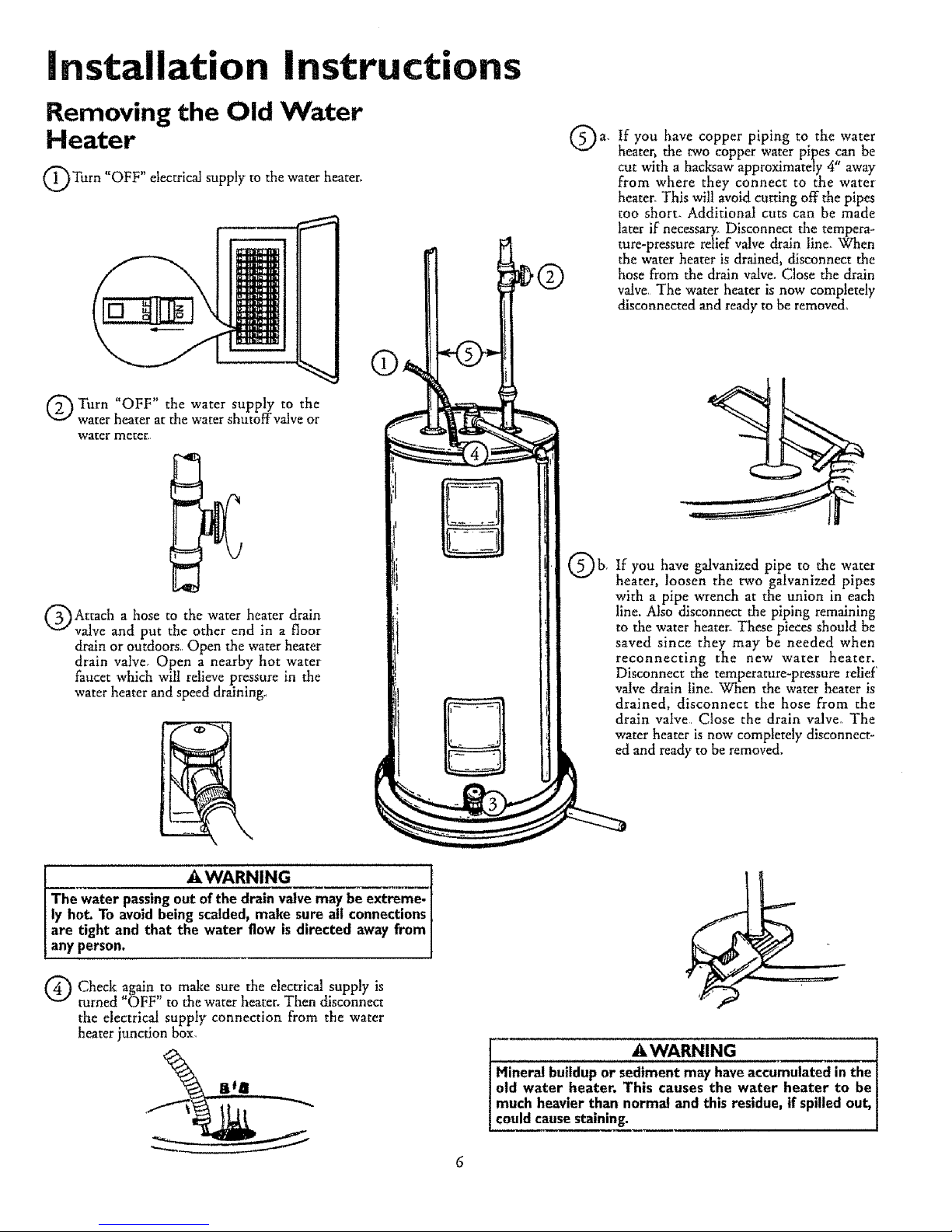
Turn "OFF" electrical supply to the water heater.
Q Turn "OFF" the water supply to the
water heater at the water shutoffvalve or
water meter_
®
QAttach a hose to the water heater drain
valve and put the other end in a floor
drain or outdoors Open the water heater
drain valve, Open a nearby hot water
faucet which will relieve pressure in the
water heater and speed draining.
J _,WARNING
The water passingour=lye may be extreme-
ly hot. To avoidbeing scalded, make sure all connections
are tight and that the water flow is directed away from
any person,
Q Check again to make sure the electrical supply is
turned "OFF" to the water heater. Then disconnect
the electrical supply connection from the water
heater junction box,
Q a. If have piping to the water
you copper
heater, the two copper water pipes can be
cut with a hacksaw approximately 4" away
from where they connect to the water
heater. This will avoid cutting off the pipes
too short. Additional cuts can be made
later if necessary: Disconnect the tempera-
ture-pressure relief valve drain line. When
the water heater is drained, disconnect the
hose from the drain valve. Close the drain
valve_ The water heater is now completely
disconnected and ready to be removed,
Q b. you galvanized pipe to water
If have the
heater, loosen the two galvanized pipes
with a pipe wrench at the union in each
line. Also disconnect the piping remaining
to the water heater_ These pieces should be
saved since they may be needed when
reconnecting the new water heater.
Disconnect the temperature-pressure relief'
valve drain line. When the water heater is
drained, disconnect the hose from the
drain valve Close the drain valve° The
water heater is now completely disconnect-
ed and ready to be removed.
Mineral buildup or sediment may have accumulated in the[
old water heater, This causes the water heater to be[
much heavier than norma! and this residue, if spilledout, I
coud causestain rig. I
installation instructions (toni'd)
Facts to Consider About the Facts to Consider About The
Location Convertible Lower Element
You should carefully choose an indoor location for the new
water heater, because the placement is a veI3, important consid-
eration for the safety of the occupants in rkle building and for
the most economical use of the appliance This water heater is
not intended for outdoor installation.
Whether replacing an old water heater or putting the water
heater in a new location, the following critical points must be
observed.
The location selected should be indoors as close to and as
centralized with the water piping system as possible. This
water heater, as well as all water heaters, will eventually leak_
Do not install without adequate drainage provisions where
water flow will cause damage..
CAUTION
WATER HEATERS EVENTUALLY LEAK= Installation of the
water heater must be accomplished in such a manner that if
the tank or any connections should leak, the flow of water
will not cause damage to the structure. For this reason it is
not advisable to nstal the water heater in an attic or upper
floor. When such locations cannot be avoided, a suitable
drain pan should be installed under the water heater° Drain
_ansare available at your local Sears Store. Such a drain pan
must be piped to an adequate drain. Under no circumstances
is the manufacturer or Sears to be held liable for any water
damage in connection with this water heater.
The Upper Element (if a double element model), is a conven-
tional 3800 watt element which only operates at its rated
wattage on 240 volts (Seerating plate on water heater)
The Lower Element of the water heater can be converted from
operation at 3800 watts to 5500 watts on a 240 volt system.
Read and follow water beater warnings and instructions If after
reading these instructions in this manual, if you do not under-
stand any portion, call Sears Service Center.
AWARNING
Before making the conversion to 5500 watts, check the
AWI) power supply..must be 240 volts, (2) wiring... 10 gauge
G, Type TW, 60°C or equivalent, and (3) Circuit
breakers or fusing...capabte of 30 amp loading. Also, the
installation must conform with this manual, local codes
and electric utility rules. Failure to comply can result in
DEATH, SERIOUS BODILY INJURY, OR PROPERTY
DAMAGE.
A CAUTION
INSTALLATION IN RESIDENTIAL GARAGES: The
water heater must be located andlor protected so it is
not subject to physical damage by a moving vehicle.
• The location selection must provide adequate clearances for
servicing and proper operation of the water heater.
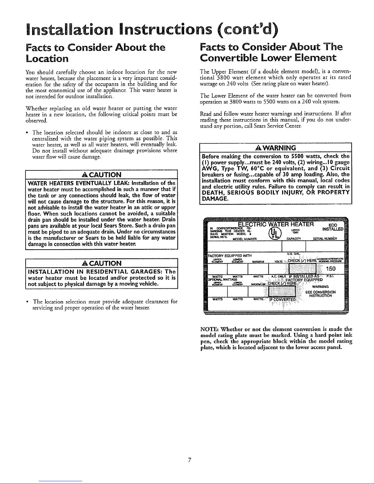
NOTE: Whether or not the element conversion is made the
model rating plate must be marked_ Using a hardpoint ink
pen, check the appropriate block within the model rating
plate, which is located adjacent to the lower access panel.

installation
Water Piping
instructions (cont'd)
AWARNING
HOTTER WATER CAN SCALD: Water heaters are
intended to produce hot water. Water heated to a tem-
)erature which will satisfy space heating, clothes washing,
dish washing, and other sanitizing needs can scald and
)ermanently injure you upon contact_ Some people are
more likely to be permanently injured by hot water than
others. These include the elderly, children, the infirm, or
physically/mentally handicapped. If anyone using hot
water in your home fits into one of these groups or if
there is a local code or state law requiring a certain tem-
)erature water at the hot water tap_ then you must tal(e
special precautions. In addition to using the lowest possi-
ble temperature setting that satisfies your hot water
needs, a means such as a mixing valve, shall be used at
the hot water taps used by these people or at the water
heater. Mixing valves are available at plumbing supply or
hardware stores. Follow manufacturers instructions for
installation of the valves_ Before changing the factory set-
ting on the thermostat, read the "Temperature
Regulation" section in this manual.
The illustration shows the attachment of the water piping to the
water heater. The water heater is equipped with ¾" water
conNectlons_
If a water heater is installed in a closed water supply system;
such as one having a back-flow preventer, check valve, water
meter with a check valve, etc, in the cold water supply; means
shall be provided to control thermal expansion, Contact the
local utility or local Sears Service Center on how to control this
situation,
NOTE: If using copper tubing, solder tubing to an adapter
before attaching the adapter to the cold water inlet connec-
tion. Do not solder the cold water supply line directly to the
cold water inlet. It will harm the dip tube and damage the
taul_
• Look at the top cover of the water heater. The water oudet is
marked hot Put two or three turns of teflon tape around the
threaded end of the threaded-to-sweat coupling and around
both ends of the ¾" threaded nipple. Using flexible connec-
tors, connect the hot water pipe to the hot water outlet of the
water heater
• Look at the top cover of the water heater The cold water inlet
is marked cold. Put two or three turns of teflon tape around
the threaded end of the threaded-to-sweat coupling and
around both ends of the ¾" threaded nipple, Using flexible
connectors, connect the cold water pipe to the cold water
inlet of the water heater.
Installation completed using Sears
Installation Kit
FLEXIBLE
WATER
CONNECTORS
.OTOUTLET
TO HOUSHEREAD_DTO
SWEAT COUPLING _
SHUT-OFF
VALVE
COLD INLET
WATER LINE
THREADED TO
SWEAT COUPLING
314"THREADED
NIPPLE
"<---'--3/4"THREADED
NIPPLE
TEMPERATURE.
PRESSURE
RELIEF VALVE
)ISCHARGE PIPE
(Do not cap or plug)
6" AIR GAP
FLOOR DRAIN
NOTE: Your water heater is super insulated to minimize
heat loss from the tanl¢_ Further reduction in heat loss can be
accomplished by insulating the hot water lines from the
water heater.
IJnstallation Instructions (cont'd)
Temperature=Pressure
Relief Valve
_kWARNIfNG
At the time of manufacture this water heater was provided
with a combination temperature-pressures relief valve cer-
tified by a nationally recognized testing laboratory that
maintains periodic inspection of production of listed equip-
ment or materials, as meeting the requirements for Relief
Valves and Automatic Gas Shutoff Devices for Not Water
Supply Systems, and the current edition of ANSI Z21,22
and the code requirements of ASHE+ If replaced, the valve
must meet the requirements of local codes, but not less
than a combination temperature and pressure relief valve
certified as meeting the requirements for Relief Valves and
Automatic Gas Shutoff Devices for Hot Water Supply
Systems, ANSI Z21.22 by a nationally recognized testing
laboratory that maintains periodic inspection of production
of listed equipment or materials.
The valve must be marked with a maximum set pressure
not to exceed the marked hydrostatic working pressure of
the water heater (150 Ibs. p.sJ.) and a discharge capacity
not less than the water heater input rate as shown on the
model rating plate. (Electric heaters - watts divided by
1000 x 3412 equal BTU/Hro rate.)
Your local jurisdictional authority, while mandating the use
of a temperature-pressure relief valve complying with
ANSI Z21.22 and ASME, may require a valve model differ-
ent from the one furnished with the water heater.
Compliance with such local requirements must be satisfied
by the installer or end user of the water heater with a
locally prescribed temperature-pressure relief valve
installed in the designated opening in the water heater in
place of the factory furnished valve.
For safe operation of the water heater, the relief valve
must not be removed from it's designated opening or
plugged.
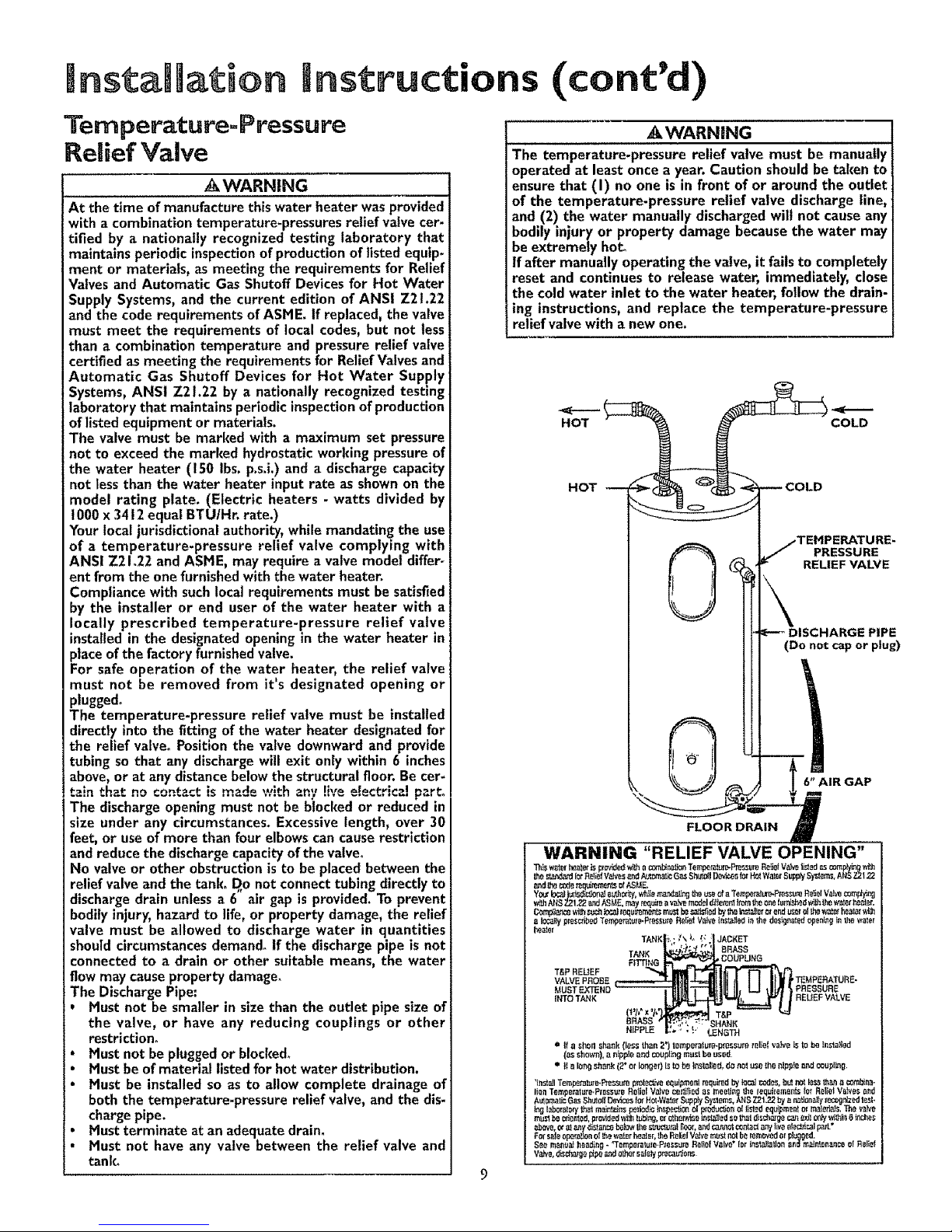
The temperature-pressure relief valve must be installed
directly into the fitting of the water heater designated for
the relief valve. Position the valve downward and provide
tubing so that any discharge will exit only within 6 inches
above, or at any distance below the structural floor. Be cer-
ta!nth_t .nocontactismade with any th,e e!ectrical p_rt+
The dischargeopening must not be blocked or reduced in
sizeunder any circumstances.Excessivelength,over 30
feet, or use of more than four elbows can cause restriction
and reduce the discharge capacity of the valve°
No valve or other obstruction is to be placed between the
relief valve and the tank. D,o not connect tubing directly to
discharge drain unless a 6 air gap is provided. To prevent
bodily injury, hazard to life, or property damage, the relief
valve must be allowed to discharge water in quantities
should circumstances demand. If the discharge pipe is not
connected to a drain or other suitable means, the water
flow may cause property damage.
The Discharge Pipe:
, Must not be smaller in size than the outlet pipe size of
the valve, or have any reducing couplings or other
restriction+
• Must not be plugged or blocked+
• Must be of material listed for hot water distribution.
• Must be installed so as to allow complete drainage of
both the temperature-pressure relief valve, and the dis.
charge pipe.
• Must terminate at an adequate drain.
• Must not have any valve between the relief valve and
tank,
_kWARNING
The temperature-pressure relief valve must be manually
operated at least once a year. Caution should be taken to
ensure that (I) no one is in front of or around the outlet
of the temperature-pressure relief valve discharge line,
and (2) the water manually discharged wilt not cause any
bodily injury or property damage because the water may
be extremely ho_
If after manually operating the valve, it fails to completely
reset and continues to release water, immediately, close
the cold water inlet to the water heater, follow the drain-
ing instructions, and replace the temperature-pressure
relief valve with a new one.
HOT
HOT
COLD
PRESSURE
RELIEF VALVE
(Do not cap or plug)
T&P REUEF
VALVE FROEE 'TEMPERATURE.
PRESSURE
REUEF VALVE
|nstallation Instructions (cont'd)
Filling the Water Heater
To fill the water heater with water:
. Close the water heater drain valve by turning the handle to
the right (clockwise)..The drain valve is on the lower front of
the water heater.
= Open the cold water supply valve to the water heater
NOTE: The cold water supply valve must be left open
when the water heater is in use,
• To insure complete filling of the tank, allow air to exit by
opening the nearest hot water faucet. Allow water to run
until a constant flow is obtained. This will let air out of the
water heater and the piping.
A CAUTION
Never usethis water heater unlessit iscompletely full of
water. To prevent damage to the tank and heating ele-
ment, the tank must be filled with water. Water must
flow from the hot water faucet before turning "ON"
power,
• Check all new water piping for leal_ Repair as needed,
Converting the Lower
Element
These instructions only cover the conversion of the convertible
element, read this entire manual before attempting to install or
operate the water heater. The water beater is factory set to oper-
ate at 3800 watts. The lower element can be converted to oper-
ate at 5500 watts, Refer to the Facts to Consider About the
Convertible Lower Element" section.
The Upper Element, (ira double element model) is a conven-
tional 3800 watt element which only operates at its rated
wattage on 240 volts..(See rating plate on water heater).
The Lower Element of the water heater can be converted from
operation at 3800 watts to 5500 watts on a 240 volt system.
If after reading these instructions and this manual, if you do not
understand any portion, call Sears Service Center.
AWARNING
Before making the conversion to 5500 watts, check the
(I) power supply...mustbe 240 volts, (2) wiring... 10gauge
AWG, Type TW, 60°C or equivalent, and (3) Circuit
breakers or fusing..capable of 30 amp loading.Also, the
installation must conform with this Manual, local codes
and electric utility rules. FAILURE TO COMPLY CAN
RESULT IN DEATH, SERIOUS BODILY INJURY OR
PROPERTY DAMAGE.
NOTE: Whether or not the element conversion is made the
model rating plate must be marked. Using a hardpoint ink
pen, check the appropriate block within the model rating
plate, which is located adjacent to the lower access panel.
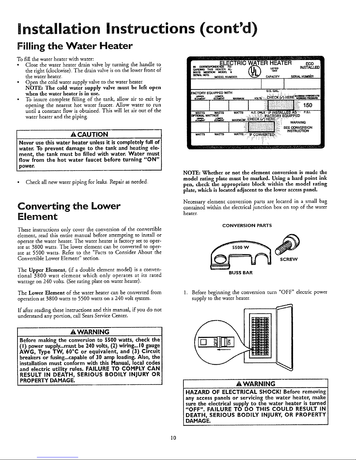
Necessary element conversion parts are located in a small bag
contained within the electrical junction box on top of the water
heater°
CONVERSION PARTS
SCRE_W
BUSS BAR
Io Before beginning the conversion turn "OFF" electric power
supply to the water heater
AWARNING
HAZARD OF ELECTRICAL SHOCKI Before removing
any accesspanels or servicing the water heater, make
sure the electrical supply to the water heater is turned
"OFF". FAILURE TO DO THIS COULD RESULT IN
DEATH, SERIOUS BODILY INJURY, OR PROPERTY
DAHAGE.
10
 Loading...