

Page 1

Use & Care Guide
Manual de Uso y Cuidado
Portable Air Conditioner
Aire Acondicionado Portatil
Models/Modelos
111.77106 - 10000 BTU
111.77126 - 12000 BTU
Sears Brands Management Corporation
Homan Estates, IL 60179 U.S.A.
www.kenmore.com
Page 2

TABLE OF CONTENTS
Safety Instructions .................................................
Features and Components .......................................
Installation ..........................................................
Control Setting .....................................................
Drainage Instructions .............................................
Maintenance ........................................................
Troubleshooting ...................................................
Warranty .............................................................
Service ...............................................................
3
5 - 6
7 - 8
9 - 10
11
12 - 13
14
15
Back Cover
Read this Use & Care Guide carefully before product use.
Keep the Use & Care Guide for later review.
Page 2
Page 3

IMPORTANT SAFETY INSTRUCTIONS
WARNING! When using electrical appliances, basic safety precautions should be
followed, including the following:
1. This air conditioner must be connected to proper electrical outlet with the correct
electrical supply.
2. Proper grounding must be ensured to reduce the risk of shock and fire. DO NOT CUT
OR REMOVE THE GROUNDING PRONG. If you do not have a three-prong electric
receptacle outlet in the wall, have a certified electrician install the proper receptacle.
The wall receptacle MUST be properly grounded.
3. Do not operate air conditioner if power cord is frayed or otherwise damaged.
Avoid using it if there are any cracks or abrasion damage along the length, plug
connector or if the unit malfunctions or is damaged in any manner. Contact an
authorized service technician for examination and repairs.
4. DO NOT USE AN ADAPTER OR AN EXTENSION CORD.
5. Do not block airflow around the air conditioner. The exhaust hose should be free of
any obstructions.
6. Always unplug the air conditioner before servicing it or moving it.
7. Do not install or use the air conditioner in any area where the atmosphere contains
combustible gases or where the atmosphere is oily or sulfurous. Avoid any chemical
coming in contact with your air conditioner.
8. Do not place any object on the top of the unit.
9. Never operate the air conditioner without filters in place.
10. Do not use the air conditioner in a bathroom or other highly humid environment.
11. Always unplug air conditioner when not in use.
12. Do not operate air conditioner with any safety devices removed.
13. Do not run power cord under carpeting. Do not cover cord with throw rugs,
runners, or the like. Arrange cord away from traffic area where it will not be
tripped over.
14. Do not block air openings or place air conditioner on a soft surface such as a
bed or sofa.
15. Do not place the air conditioner on a small, unlevel, uneven or any other surface
which might allow the unit to tip or fall.
16. For proper operation, air conditioner should be placed on a smooth,
noncombustible surface. Always place this air conditioner on a level surface at
least 20” (50 cm) away from any wall or object.
17. This appliance is not intended for use by persons (including children) with reduced
physical, sensory or mental capabilities, or lack of experience and knowledge,
unless they have been given supervision or instruction concerning use of the
appliance by a person responsible for their safety.
18. Always insert the filters securely. Clean the filters every two weeks.
19. Operating with clogged filters may cause failures.
Page 3
Page 4

IMPORTANT SAFETY INSTRUCTIONS
20. When moving the unit, make sure that it is in an upright position.
21. Keep the unit away from gasoline, flammable gas, stoves and other heat sources.
22. Don't disassemble, overhaul or modify the air conditioner, otherwise it will cause a
malfunction or possibly bring harm to persons and properties. To avoid hazard,
if a unit failure occurs, have the unit repaired before attempting to use it.
23. Do not install and use the air conditioning in the bathroom or other humid
environments.
24. Do not pull the plug to turn off the unit operation.
25. Do not place cups or other objects on the body to prevent water or other liquids
from spilling into the air conditioner.
26. Do not use insecticide sprays or other flammable substances near the air
conditioning.
27. Do not wipe or wash the air conditioner with chemical solvents such as gasoline
and alcohol. When you need to clean the air conditioner, you must disconnect
the power supply, and clean it with a half-wet soft cloth. If the unit is very dirty,
scrub with a mild detergent.
28. The appliance can be used by children aged from 8 years and above if they have
been given supervision or instruction concerning use of the appliance in a safe
way and understand the hazards involved.
29. This appliance is intended for indoor residential use only, not for industrial or
other commercial applications.
30. This appliance is intended for private household use only!
SAVE THESE INSTRUCTIONS
Power Plug
The power plug contains a device that senses damage to
the power cord.
To test the power cord:
1. Plug in the air conditioner. The plug has a Test and a
Reset button.
2. Press the TEST button and notice a click as the RESET
button pops out.
3. Press the RESET button. You will also hear a click as the
RESET button engages.
4. The power cord will now supply electricity to the unit.
5. Always make sure the RESET button in pushed in for
correct operation. The power cord must be replaced if
it fails to reset after this test.
Page 4
RESET
TEST
Page 5

FEATURES AND COMPONENTS
This air conditioner features cooling, dehumidification, fan-only, and continuous water
drainage functions.
The air louvers in top of the unit have an automatic air swing function that is activated
from the remote control
The remote control can be placed on the back of the body for convenient out of the
way storage.
Handles on both sides make unit easier to carry.
The plug storage plate enables the plug to be inserted into the back of the unit
during storage.
Operation of the unit provides continuous air filtration.
The Timer function provides for automatic shutoff and delayed starting.
The unit is equipped with a variety of protection functions, such as automatic
defrosting and a water pan overflow signal.
The unit features thermostatic operation. The thermostat senses the temperature of the
air surrounding the unit. When the air reaches the set cooling temperature, the
compressor shuts off and the fan continues to run at low speed. When the surrounding
air temperature increases by approximately 2⁰F, the compressor restarts to cool the air
to the set temperature.
The dehumidification mode combines compressor operation and low fan speed to
reduce humidity in damp rooms. Keep room doors and windows closed for effective
dehumidification. The fan speed cannot be varied when the unit is set to dehumidify.
The display screen will show dh; it will not show the relative humidity percentage of
the air.
Page 5
Page 6
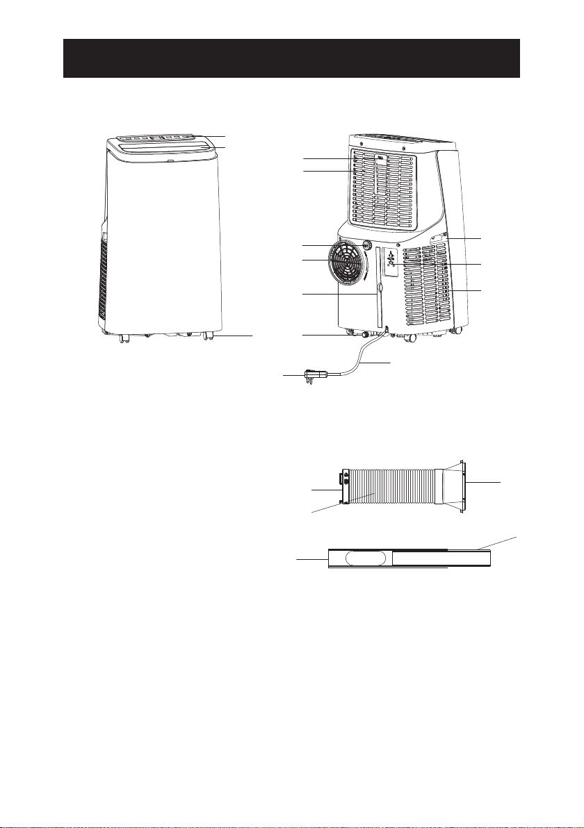
FEATURES AND COMPONENTS
Front Back
1
2
4
5
1. Control Panel
2. Air Louvers
3. Casters
4. Remote Control Storage
5. Upper Filter Grille
6. Drainage Tube Port
7. Air Exhaust Vent
8. Lower Filter Screen
9. Lower Drainage Port
10. Handle
11. Plug Storage Plate
12. Lower (Air Intake) Filter Grille
13. Power Cord
14. 3-prong Power Plug
15. Air Exhaust Hose Inlet Coupler
16. Air Exhaust Hose
17. Air Exhaust Hose Flared
Outlet Coupler
18. Window Slider Kit Piece 1
19. Window Slider Kit Piece 2
6
7
8
9
3
14
Air Exhaust Assembly
15
16
18
10
11
12
13
17
19
Not Shown
· 3 L Brackets
· 2 Straight Brackets
· 2 Foam Strips (Adhesive)
· 1 Foam Strip (Non-adhesive)
· Drainage Tube
Page 6
Page 7
INSTALLATION AND ADJUSTMENT
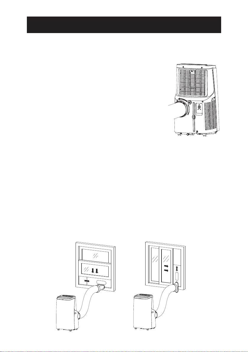
Air Exhaust Hose Installation
The couplers for the inlet and outlet ends of the air
exhaust hose are shipped preattached to the hose.
Ensure that they are securely screwed into place on
the hose before hose installation.
1. Insert the hose inlet end coupler into the air
exhaust vent. Turn coupler in the direction of
the Lock arrows (counterclockwise) to secure
the coupler in place. See Fig. 1.
2. Position the flared opening of the hose outlet
over the elliptical opening in slider piece 1.
3. Push the tabs at the top of the flared outlet into
the slots on slider piece 1. Slide the hose outlet
to the side so that the tabs engage in the slots.
4. Use a screw to secure the flared outlet to slider
piece 1 on the side of the elliptical opening that
will be nearest to the window frame.
5. Insert slider piece 2 into piece 1 and push until tight
against the flared outlet ridge protruding through the
elliptical opening. You may need to trim material off of
the inner end of piece 2 to fit the width of the window opening.
NOTE: If the window is narrower than 20.5”, use only slider piece 1. Shorten the
piece by cutting material from the end that is furthest from the hole. Do not cut
from the end that is nearest to the hole.
Position Unit Near Window
IMPORTANT! Before using the air conditioner, keep it upright for at least two hours.
The four casters on the air conditioner base allow it to be easily pushed in an upright
position across a level floor. There are handles on each side of the unit to allow it to
be lifted straight up if necessary.
CAUTION! To avoid injury, use proper lifting technique when lifting the unit by its
handles. Do not bend over from waist with legs straight. Bend knees down to lift
with back straight.
Fig.1
Page 7
Page 8
INSTALLATION
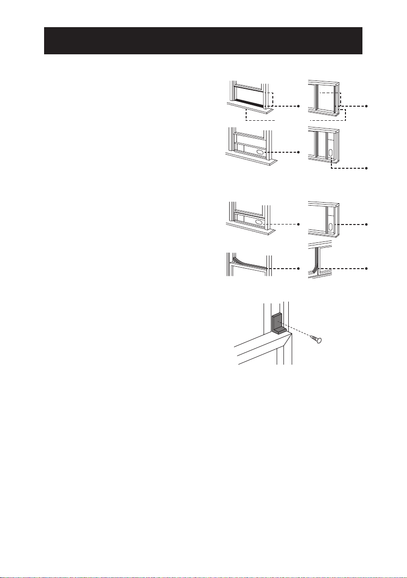
Mount the Window Slider Kit
1. Cut a length of foam seal (adhesive
type) to the proper window opening
width and attach it to the window sash.
2. Extend the air exhaust hose to
necessary length. Place the window
slider kit (with flared outlet attached)
onto the window sash.
3. Cut a length of foam seal (adhesive
type) to the proper width and attach it
to the bottom (horizontally hung) or
side (vertically hung) of the window.
4. Close the window securely onto the
window slider kit.
5. Cut the foam seal (non-adhesive type)
to an appropriate length and seal the
open gap at the top of the window
frame.
NOTE: You may use one of the supplied
L brackets to secure the window closed (see
figure to the right). Also, you may use the
two supplied straight brackets to secure the
top side of the slider kit to the window, and
the other two L brackets to secure the
bottom side of the slider kit to the window
frame.
20.5” - 59”
Foam
Seal
Window Sash
Window
Slider Kit
Window
Slider Kit
Foam
Seal
Foam
Seal
20.5” - 59”
Window
Slider Kit
Window
Slider Kit
Foam
Seal
NOTE: The length of the exhaust hose can be extended to 59 inches, but it is
best to keep the length to a minimum. Make sure that the hose does not have
any sharp bends. Do not use extension tubes or replace the supplied exhaust
hose with a different hose, or a malfunction may result. There must be no
obstructions within the hose, or the unit may overheat.
Page 8
Page 9

CONTROL SETTINGS
LED Control Panel
21 37 8 4 5 6
1. Timer Key 2. Fan Speed Selection Key 3. Up Key 4. Down Key
5. Mode Selection Key 6. Power Key 7. Sleep Mode 8. Display Screen
Plug the power cord of the unit into a 3-prong wall receptacle. You will hear a
beep and the display screen will illuminate, showing digits for the surrounding air
temperature. Press the Power Key. The air louvers on the front of the unit will
open and the unit will begin operating in Cool mode. Press Up or Down key to
adjust Cool temperature setting. Press Mode key to toggle from Cool to Dry
(dehumidification) to Fan (fan-only) operation mode.
1 Timer Key – The Timer can be set from 1 to 24 hours in one-hour increments.
Shutoff Time – With power on, press the Timer key. Digits will start to flash in the
display and the Hr indicator will light. While display is flashing, press the up and
down keys to select the desired number of run time hours. After a few seconds the
temperature digits will display and the Hr indicator will remain lit. The unit will run
for the set time and then shut off.
Delayed Start Time – With the power off, press the Timer key. Digits will start to
flash in the display and the Hr indicator will light. While the display is flashing, press
the up and down keys to select the desired number of hours before startup. After a
few seconds the temperature digits will display and the Hr indicator will remain lit.
The unit will begin to run after the set number of hours has passed.
To cancel Timer settings press the Timer key twice in quick succession. The Hr
indicator will turn off.
The Timer can be set from 1 to 24 hours and the amount of time is adjustable by
one-hour increments.
2 Fan Speed Selection Key – In Cool and Fan mode, press the Fan key to select high
(F2) or low (F1) fan speed. In Dehum mode, the fan defaults to the lowest speed (F1).
3, 4 Up and Down Keys – Press the up or down key to adjust the desired cooling
temperature. While pressing Timer key, press up or down key to select the desired
shutoff or delayed start time span. Simultaneously press both keys to switch between
Celsius (°C) and Fahrenheit (°F).
5 Mode Selection Button – Press Mode key to switch between modes. With each
press, the mode indicator will light up in sequence from Cool ---> Dehum ---> Fan
Page 9
Page 10

CONTROL SETTINGS
6 Power Key – Press the key to turn unit operation on or off. With key off the
display shows surrounding air temperature.
7 Sleep Mode – In Cool mode, press the up key and fan key at same time to turn on
Sleep mode. After one hour the temperature setting will increase by one degree, and
by one more degree after another hour, to accord with how your body naturally
cools while asleep. Fan speed is low for quiet operation. Press up and fan key at
same time to turn Sleep mode off. The temperature will return to original setting.
Remote Control
Point the remote control at the unit control panel when pressing remote control keys.
You will hear the unit beep to confirm remote control key activation.
1 Power – Press key to turn unit operation on and off.
2 Timer – Press TIMER key to set the timer.
3 Auto-Swing Function – Press SWING key to start
Oscillation mode.
4 Sleep – Press SLEEP key to turn on sleep mode.
5 Down – Press key to reduce temperature and
adjust timer setting.
6 Up – Press key to increase the temperature and adjust
timer setting.
7 Mode – Press MODE key to switch between cooling,
dehumidifying and fan-only mode.
8 Fan – Press FAN key to select high or low wind speed.
9 Temperature unit converter – ⁰F ⁰C
Protective Functions
Frost Protection – In Cool and Dry modes, if the temperature of the compressor
becomes too low, the unit will automatically enter protection status. Once coil rises
to a sufficient temperature, the unit will automatically revert to normal operation.
Overflow Protection – When water in the water pan exceeds the maximum level,
the unit will beep, stop running, and the display screen will show FL. The water in
the pan must be drained empty before the unit will resume operation. See the
Drainage Instructions in the next section of this Use & Care Guide.
Automatic Defrosting – The air conditioner has automatic defrosting. During
defrosting, the compressor will stop working for about 3-5 minutes, during which
time the fan continues to run.
Automatic Thermal Protection – The air conditioner has automatic thermal
protection to protect against overheating. When thermal protection is activated,
the compressor and motor will stop. Once cooled to a safe operation temperature,
the unit can be restarted.
Page 10
Page 11

DRAINAGE INSTRUCTIONS
Manual drainage
1. When the unit stops after the water pan is full,
press the power key to turn off power to the unit,
and then unplug the power plug. Note: Move the
unit carefully so as not to spill the water in the
water pan at the base.
2. Place a water container below the bottom
drainage port of the unit.
3. Unscrew the drain cap and remove the water
plug. Water will automatically flow into the
water container.
Notes
· During drainage, tilt the unit slightly backwards.
· If you see that your water container will not
hold all the water, before it is full insert the water plug
back into the drain port to prevent water from spilling
onto the floor.
4. When the all the water is drained from the unit, insert the
water plug and retighten the drain cap.
Continuous drainage
1. Unscrew the drain cap and remove the
water plug from the drainage tube port
in the middle back of the unit.
2. Push one end of the drainage tube into
the drainage port.
3. Set the other end of the drainage tube
into a water container or floor drain.
Allow water pan to drain.
Note: If your water container becomes
full, a water backup may occur that
will fill the unit water pan and result in
unit shutdown. Remove the adapter end
and place into another empty container or floor drain.
Allow water pan to drain.
4. When the all the water is drained from the unit, insert
the water plug and retighten the drain cap.
Page 11
Page 12

MAINTENANCE
Cleaning
Before cleaning and maintenance, press the power key is pressed to off and unplug
the power cord from the electrical outlet.
Clean the exterior surface
Clean with surface of machine with a wet soft cloth. Don't use chemicals such as
alcohol, gasoline, etc.; otherwise, the surface of the air conditioning will be
damaged or even the whole machine will be damaged.
Clean the lter screens
If the filter screens become clogged with dust the effectiveness of the air
conditioner is reduced. Be sure to clean the filter screens once every two weeks.
To clean upper lter screen
1. Remove Remote Control from storage slot
in upper filter grille.
2. Insert fingertips beneath PULL tab at top
of screen grille and pull outward
to remove.
3. Remove upper filter screen. Place the
screen into warm water (about 104°F/40°C)
with mild detergent and allow it to air dry
after rinsing clean.
4. Once screen is completely dry, insert back
into place in unit.
5. To reinstall grille, insert tabs at bottom of
grille into slots in unit frame. Push grille
forward to snap into place.
To clean the lower lter screen
1. Grasp the tab in the middle of the lower filter screen and pull outward
gently to remove it.
2. Place the filter screen into warm water (about 104°F/40°C) with mild
detergent and allow it to air dry after rinsing clean.
3. Once screen is completely dry, insert back into place in unit.
To purchase new filter screens call 1-844-553-6667
Page 12
Page 13

MAINTENANCE
Postseason Storage
1. If unit is hooked up for continuous drainage, unscrew the middle drain cap,
unplug the water plug, and discharge the water into other water containers
or floor drain. If unit is not connected for continuous drainage, empty the
pan according to the manual drainage instructions.
2. Turn on the air conditioner, adjust it to low-low fan speed, and run unit until
for a period of time so as to dry out moisture from inside the unit to prevent
formation of mildew during storage.
3. Turn off the air conditioner, unplug the power plug from wall receptacle
and insert the power plug prongs into the plug storage plate on the back of
the unit. Reinstall the water plug and the drainage cap.
4. Remove the air exhaust hose and store in a secure place.
5. Cover the air conditioner with a plastic bag. Store the unit in a dry place,
keep it out of the reach of children, and take dust control measures.
Page 13
Page 14

TROUBLESHOOTING
If problems not listed in the table occur or recommended solutions do not work, contact a
qualified service dealer for repair. Do not disassemble the air conditioner. Unqualified
repair will void the warranty, and may cause injury to users or damage to property.
Problems Reasons Solutions
The air
conditioner
does not work.
There is no electricity.
The overflow indicator displays FL.
The ambient temperature is too low or
too high
In cooling mode, the room
temperature is lower than the set
temperature
Turn unit on after connecting it to a
socket with electricity.
Discharge the water inside.
Run the unit within the ambient
temperature range of 44-95 ˚F
(7-35˚C).
Change the set temperature.
The cooling effect
is not good
Loud Noise
Compressor does
not work.
The remote control
does not work.
Display reads E1
Display reads E2
In dehumidification mode, the ambient
temperature is low.
There is direct sunlight.
Doors or windows are open; there are a
lot of people in the room; or in cooling
mode, there are other sources of heat.
The filter screen is dirty.
The air inlet or outlet is blocked.
The air conditioner is not placed on a
flat surface.
Overheat protection is active.
The distance between the unit and the
remote control is too far.
The remote control is not aligned with
the direction of the remote control
receiver.
Batteries are dead.
The coil temperature sensor is
malfunctioning.
The room temperature sensor is
malfunctioning.
Place the unit in a room with an
ambient temperature of greater than
62 ˚F (17 ˚C).
Pull the room curtain closed.
Close doors and windows, and add
new air conditioner.
Clean or replace the filter screen.
Clear obstructions.
Put the air conditioner on a flat and
hard place (to reduce noise).
Wait for 3 minutes until unit cools, then
restart.
Move the remote control closer to the
air conditioner, and make sure that the
remote control directly faces in the
direction of the remote control receiver
on the unit.
Replace batteries.
Call for service.
Call for service.
Page 14
Page 15

WARRANTY
KENMORE LIMITED WARRANTY
FOR ONE YEAR from the date of sale this appliance is warranted against defects in material or
workmanship when It is correctly installed, operated and maintained according to all supplied
instructions.
WITH PROOF OF SALE a defective appliance will receive free repair or replacement at option
of seller.
For warranty coverage details to obtain free repair or replacement, visit the web
page: www.kenmore.com/warranty
This warranty applies for only 90 DAYS from the date of sale if this appliance is ever used for other
than private household purposes.
This warranty covers ONLY defects in material and workmanship, and will
NOT pay for:
1. Expendable items that can wear out from normal use, including but not limited to filters, belts,
bags or screw-in base light bulbs.
2. A service technician to clean or maintain this appliance, or to instruct the user in correct
appliance installation, operation and maintenance.
3. Service calls to correct appliance installation not performed by Sears authorized service agents,
or to repair problems with house fuses, circuit breakers, house wiring, and plumbing or gas
supply systems resulting from such installation.
4. Damage to or failure of this appliance resulting from installation not performed by Sears
authorized service agents, including installation that was not in accord with electrical, gas or
plumbing codes.
5. Damage to or failure of this appliance, including discoloration or surface rust, if it is not
correctly operated and maintained according to all supplied instructions.
6. Damage to or failure of this appliance, including discoloration or surface rust, resulting from
accident, alteration, abuse, misuse or use for other than its intended purpose.
7. Damage to or failure of this appliance, including discoloration or surface rust, caused by the use
of detergents, cleaners, chemicals or utensils other than those recommended in all instructions
supplied with the product.
8. Damage to or failure of parts or systems resulting from unauthorized modifications made to
this appliance.
9. Service to an appliance if the model and serial plate is missing, altered, or cannot easily be
determined to have the appropriate certification logo.
Disclaimer of implied warranties: limitation of remedies
Customer's sole and exclusive remedy under this limited warranty shall be product repair or
replacement as provided herein. Implied warranties, including warranties of merchantability or
fitness for a particular purpose, are limited to one year or the shortest period allowed by law. Seller
shall not be liable for incidental or consequential damages. Some states and provinces do not
allow the exclusion or limitation of incidental or consequential damages, or limitation on the
duration of implied warranties of merchantability or fitness, so these exclusions or limitations may
not apply to you.
This warranty applies only while this appliance is used in the United States.
This warranty gives you specific legal rights, and you may also have other rights which vary from
state to state.
Sears Brands Management Corporation, Hoffman Estates, IL 60179
Page 15
Page 16

TABLA DE CONTENIDO
Instrucciones de seguridad ......................................
Características y componentes ..................................
Instalación ..........................................................
Configuración de control .........................................
Instrucciones de drenaje .........................................
Mantenimiento .....................................................
Solución de problemas ...........................................
Garantía .............................................................
Servicio ..............................................................
3
5 - 6
7 - 8
9 - 10
11
12 - 13
14
15
Contraportada
Lea esta Guía de uso y cuidado cuidadosamente antes
de usar este producto.
Guarde la Guía de uso y cuidado para revisión en
un futuro
Page 16
Page 17

INSTRUCCIONES DE SEGURIDAD
¡ADVERTENCIA! Al usar aparatos eléctricos, se deben seguir precauciones de
seguridad básicas, que incluyen las siguientes:
1. Este aire Acondicionado debe estar conectado a una toma de corriente adecuada
con el suministro eléctrico correcto.
2. Se debe garantizar una conexión a tierra adecuada para reducir el riesgo de
descarga e incendio. NO CORTE NI QUITE LA CONEXIÓN A TIERRA. Si no tiene una
toma de corriente eléctrica de tres patas en la pared, solicite a un electricista
certificado que instale el receptáculo adecuado. El receptáculo de pared DEBE estar
debidamente conectado a tierra.
3. No opere el aire acondicionado si el cable de alimentación está desgastado o
dañado. Evite usarlo si hay grietas o daños por abrasión a lo largo, el conector o si la
unidad funciona mal o está dañada de alguna manera. Póngase en contacto con un
técnico de servicio autorizado para examinar y reparar la unidad.
4. No utilice un adaptador o un alargador
5. No bloquee el flujo de aire alrededor del aire acondicionado. La manguera de
escape debe estar libre de obstrucciones.
6. Desenchufe siempre el aire acondicionado antes de repararlo o moverlo.
7. No instale ni use el aire acondicionado en ninguna área donde la atmósfera
contenga gases combustibles o donde la atmósfera sea aceitosa o sulfurosa.
Evite cualquier sustancia química que entre en contacto con su aire acondicionado.
8. No coloque ningún objeto en la parte superior de la unidad.
9. Nunca opere el aire acondicionado sin filtros.
10. No use el aire acondicionado en un baño u otro ambiente altamente húmedo.
11. Siempre desconecte el aire acondicionado cuando no esté en uso.
12. No opere el aire acondicionado con ningún dispositivo de seguridad retirado.
13. No pase el cable de alimentación debajo de las alfombras. No cubra el cable con
ningún tipo de tapetes, o alfombras. Arregle el cable de manera que no obstruya el
paso para evitar que alguien se tropecé.
14. No bloquee las aberturas de aire ni coloque el aire acondicionado sobre una
superficie blanda, como una cama o sofá.
15. No coloque el aire acondicionado sobre una superficie pequeña, desigual, irregular
o cualquier otra que pueda permitir que la unidad se vuelque o se caiga.
16. Para una operación adecuada, el aire acondicionado debe colocarse sobre una
superficie lisa y no combustible. Siempre coloque este aire acondicionado en una
superficie nivelada a una distancia mínima de 20 "(50 cm) de cualquier pared u objeto.
17. Este electrodoméstico no debe ser utilizado por personas (incluidos niños) con
discapacidades físicas, sensoriales o mentales, o por falta de experiencia y
conocimiento, a menos que una persona responsable de su seguridad les haya
dado supervisión o instrucciones sobre el uso del electrodoméstico.
18. Siempre inserte los filtros de forma segura. Limpia los filtros cada dos semanas.
19. Operar con filtros obstruidos puede causar fallas.
Page 17
Page 18

INSTRUCCIONES DE SEGURIDAD
20. Cuando mueva la unidad, asegúrese de que esté en posición vertical.
21. Mantenga la unidad alejada de la gasolina, gases inflamables, estufas y otras
fuentes de calor.
22. No desarme, revise o modifique el aire acondicionado, de lo contrario causará un
mal funcionamiento o posiblemente cause daños a personas y propiedades.
Para evitar riesgos, si ocurre una falla en la unidad, mande a reparar la unidad antes
de intentar usarla.
23. No instale y use el aire acondicionado en el baño u otros ambientes húmedos.
24. No desconecte el enchufe para apagar la unidad.
25. No coloque tazas u otros objetos sobre el cuerpo de la unidad para evitar que el
agua u otros líquidos se derramen en el aire acondicionado.
26. No use aerosoles insecticidas u otras sustancias inflamables cerca del aire
acondicionado.
27. No limpie ni lave el acondicionador de aire con solventes químicos como gasolina y
alcohol. Cuando necesite limpiar el aire acondicionado debe desconectar la fuente
de alimentación y limpiarlo con un paño suave medio húmedo. Si la unidad está
muy sucia, frote con un detergente suave.
28. El aparato puede ser utilizado por niños mayores de 8 años si se les ha supervisado
o instruido sobre el uso del artefacto de una manera segura y comprende los
riesgos involucrados.
29. Este electrodoméstico está diseñado solo para uso residencial en interiores, no para
aplicaciones industriales ni comerciales.
30. ¡Este aparato está destinado solo para uso doméstico privado!
GUARDE ESTAS INSTRUCCIONES
Enchufe
El enchufe de alimentación contiene un dispositivo que
detecta daños en el cable de alimentación.
Para probar el cable de alimentación:
1. Conecte el aire acondicionado. El enchufe tiene una
prueba y un botón de reinicio.
2. Presione el botón de PRUEBA y escuchara un clic
mientras el botón RESET se sale.
3. Presione el botón RESET. Escuchará un clic cuando el
botón RESET se active.
4. El cable de alimentación ahora suministrará electricidad
a la unidad.
5. Asegúrese siempre de presionar el botón RESET para una
operación correcta. El cable de alimentación debe
reemplazarse si no se restablece después de esta prueba.
Page 18
RESET
TEST
Page 19

CARACTERÍSTICAS Y COMPONENTES
Este aire acondicionado cuenta con funciones de enfriamiento, deshumidificación,
ventilador y drenaje continuo de agua.
Las rejillas de ventilación en la parte superior de la unidad tienen una función de
oscilación de aire automática que se activa desde el control remoto
El control remoto se puede colocar en la parte posterior de la unidad para un
almacenamiento conveniente.
Las manijas en ambos lados hacen que la unidad sea más fácil de transportar.
La placa de almacenamiento de enchufe permite que el enchufe se inserte en la parte
posterior de la unidad durante el almacenamiento.
El funcionamiento de la unidad proporciona una filtración de aire continua.
La función del temporizador permite el apagado automático y el inicio diferido.
La unidad está equipada con una variedad de funciones de protección, como
descongelación automática y una señal de desbordamiento de bandeja de agua.
La unidad cuenta con operación termostática. El termostato detecta la temperatura del
aire que rodea la unidad. Cuando el aire alcanza la temperatura de enfriamiento
configurada, el compresor se apaga y el ventilador continúa funcionando a baja
velocidad. Cuando la temperatura del aire circundante aumenta en aproximadamente
2⁰F, el compresor se reinicia para enfriar el aire a la temperatura establecida.
El modo de deshumidificación combina el funcionamiento del compresor y la baja
velocidad del ventilador para reducir la humedad en las habitaciones húmedas.
Mantenga las puertas y ventanas de la habitación cerradas para una deshumidificación
efectiva. La velocidad del ventilador no puede variarse cuando la unidad está
configurada para deshumidificar. La pantalla de visualización mostrará dh; no mostrará
el porcentaje de humedad relativa del aire.
Page 19
Page 20

CARACTERÍSTICAS Y
Frente Parte Posterios
1
2
4
5
3
1. Panel de control
2. Rejillas
14
3. Ruedas
4. Almacenamiento para control remoto
5. Parrilla superior del filtro
6. Puerto del tubo de drenaje
7. Salida de escape de aire
8. Pantalla de filtro inferior
9. Baje el puerto de drenaje
10. Manija
11. Placa de almacenamiento de enchufe
12. Rejilla de filtro inferior (entrada de aire)
13. Cable de alimentación
14. Enchufe de 3 clavijas
15. Acoplador de entrada de la manguera
de escape de aire
16. Manguera de escape de aire
17. Manguera de escape de aire quemado
Acoplador de salida
18 kit de control deslizante de ventana 1
19. Kit de control deslizante de ventana 2
6
7
8
9
13
Asamblea de escape de aire
15
16
18
10
11
12
17
19
No mostrada
· 3L Corchete
· 2 Soporte directo
· 2 Franja de poliestirenco (Adhesivo)
· 1 Franja de poliestireno
· Tubo de drenaje
Page 20
Page 21

INSTALACION
Instalación de la manguera de escape de aire
Los acopladores para los extremos de entrada y salida de la
manguera de escape de aire se envían preinstalados a la
manguera. Asegúrese de que estén firmemente atornillados en
su lugar en la manguera antes de instalar la manguera.
1. Inserte el acoplador del extremo de entrada de la manguera
en el orificio de salida de aire. Gire el acoplador en la
dirección de las flechas de Bloqueo (hacia la izquierda) para
asegurar el acoplador en su lugar. Ver la Fig. 1.
2. Coloque la abertura acampanada de la salida de la
manguera sobre la abertura elíptica en la pieza deslizadora
3. Empuje las pestañas en la parte superior de la salida 1.
abocardada en las ranuras de la barra deslizadora 1.
Deslice la salida de la manguera hacia un lado para que
las pestañas encajen en las ranuras.
4. Use un tornillo para asegurar la salida abocardada a la pieza
deslizadora 1 en el lado de la abertura elíptica que estará
más cerca del marco de la ventana.
5. Inserte la pieza deslizante 2 en la pieza 1 y presione hasta
que quede apretada contra la cresta de salida acampanada
que sobresale a través de la apertura elíptica. Es posible que deba recortar el material del extremo
interno de la pieza 2 para adaptarse al ancho de la abertura de la ventana.
NOTA: Si la ventana es más estrecha que 20.5 ", use solo la barra deslizadora 1. Acorte la pieza
cortando material del extremo que está más alejado del orificio. No corte desde el extremo más
cercano al orificio.
Posición de la unidad cerca de la ventana
¡IMPORTANTE! Antes de usar el aire acondicionado, manténgalo en posición vertical durante al
menos dos horas.
Las cuatro rueditas en la base del acondicionador de aire permiten que se pueda empujar fácilmente
en una posición vertical a través de un piso nivelado. Hay asas a cada lado de la unidad para permitir
que se levante hacia arriba si es necesario.
¡PRECAUCIÓN! Para evitar lesiones, use la técnica de levantamiento adecuada al levantar la unidad
por sus asas. No se doble de la cintura con las piernas estiradas, Doblar las rodillas para levantar con la
espalda recta.
Fig.1
Page 21
Page 22

INSTALACION
Monte el kit de corredera de ventana
1. Corte un trozo de sello de espuma
(tipo adhesivo) en el ancho de abertura
de la ventana adecuada y fíjelo a la hoja
de la ventana.
2. Extienda la manguera de escape de aire
a la longitud necesaria. Coloque el kit
de deslizador de la ventana (con salida
abocardada adjunta) en la hoja de la
ventana.
3. Corte un trozo de sello de espuma
(tipo adhesivo) con el ancho adecuado
y conéctelo a la parte inferior (colgando
horizontalmente) o al costado (colgando
verticalmente) de la ventana.
4. Cierre la ventana de forma segura en el
kit deslizante de la ventana.
5. Corte el sello de espuma (tipo no
adhesivo) a una longitud adecuada
y selle el espacio abierto entre la parte
superior del marco de la ventana.
20.5” - 59”
Cello de
espuma
Marco de la ventana
Kit de
deslizador
de Ventana
Kit de
deslizador
de Ventana
Cello de
espuma
Cello de
espuma
20.5” - 59”
Kit de
deslizador
de Ventana
Kit de
deslizador
de Ventana
Cello de
espuma
NOTA: puede usar uno de los suministrados
L corchetes para asegurar la ventana cerrada
(ver figura a la derecha). Además, puede
usar los dos soportes rectos suministrados
para asegurar el lado superior del kit
deslizante a la ventana, y los otros dos
soportes L para asegurar el lado inferior
del kit deslizante al marco de la ventana.
NOTA: La longitud de la manguera de escape puede extenderse a 59
pulgadas, pero es mejor mantener la longitud a un mínimo. Asegúrese de que
la manguera no tenga curvas cerradas. No use tubos de extensión ni reemplace
la manguera de escape suministrada con una manguera diferente, ya que
podría producirse un mal funcionamiento. No debe haber obstrucciones
dentro de la manguera, o la unidad puede sobrecalentarse.
Page 22
Page 23

CONFIGURACIÓN DE CONTROL
LED Panel de Control
21 37 8 4 5 6
1. Tecla del tempo 2. Tecla de selección de velocidad del ventilador
3. Tecla Arriba 4. Tecla Abajo
5. Tecla de selección de modo 6. Tecla de encendido
7. Modo de reposo 8. Pantalla de visualización
Enchufe el cable de alimentación de la unidad en un receptáculo de pared de 3 patas.
Escuchará un pitido y la pantalla se iluminará, mostrando los dígitos de la temperatura del aire
circundante. Presiona la tecla de encendido. Las rejillas de ventilación en la parte frontal de la
unidad se abrirán y la unidad comenzará a funcionar en el modo Frío. Presione la tecla Arriba o
Abajo para ajustar la temperatura de enfriamiento. Presione la tecla Modo para alternar entre el
modo de funcionamiento Frío a Seco (deshumidificación) y Ventilador (solo ventilador).
1. Tecla de temporizador: el temporizador se puede configurar de 1 a 24 horas en
incrementos de una hora. Tiempo de apagado: con la energía encendida, presione la tecla del
temporizador. Los dígitos comenzarán a parpadear en la pantalla y el indicador Hr se
encenderá. Mientras la pantalla parpadea, presione las teclas hacia arriba y hacia abajo para
seleccionar la cantidad deseada de horas de funcionamiento. Después de unos segundos, se
mostrarán los dígitos de temperatura y el indicador Hr permanecerá encendido. La unidad
funcionará durante el tiempo establecido y luego se apagará. Tiempo de inicio demorado: con
la alimentación apagada, presione la tecla del temporizador. Los dígitos comenzarán a
parpadear en la pantalla y el indicador Hr se encenderá. Mientras la pantalla parpadea, presione
las teclas hacia arriba y hacia abajo para seleccionar el número deseado de horas antes del
inicio. Después de unos segundos, se mostrarán los dígitos de temperatura y el indicador Hr
permanecerá encendido. La unidad comenzará a funcionar después de que haya transcurrido
el número de horas establecido. Para cancelar la configuración del temporizador, presione la
tecla del temporizador dos veces seguidas. El indicador Hr se apagará. El temporizador se
puede configurar de 1 a 24 horas y la cantidad de tiempo se puede ajustar en incrementos de
una hora.
2. Tecla de selección de velocidad del ventilador: en el modo de refrigeración y ventilador,
presione la tecla de ventilador para seleccionar la velocidad del ventilador alto (F3), medio (F2)
o bajo (F1). En el modo Seco, el ventilador se predetermina a la velocidad más baja (F1).
3, 4. Teclas arriba y abajo - Presione la tecla arriba o abajo para ajustar la temperatura de
enfriamiento deseada. Mientras presiona la tecla del temporizador, presione la tecla hacia
arriba o hacia abajo para seleccionar el intervalo de apagado deseado o de inicio diferido.
Presione simultáneamente ambas teclas para cambiar entre Celsius (˚C) y Fahrenheit (˚F).
5. Botón de selección de modo: presione la tecla de modo para alternar entre modos. Con
cada presión, el indicador de modo se iluminará en secuencia desde Frio---> Deshumidificación
---> Ventilador
Page 23
Page 24

CONFIGURACIÓN DE CONTROL
6 .Tecla de encendido: presione la tecla para encender o apagar el funcionamiento de la
unidad. Con la tecla apagada, la pantalla muestra la temperatura del aire circundante.
7. Modo de suspensión: en el modo de refrigeración, presione la tecla hacia arriba y la tecla
de ventilador al mismo tiempo para encender el modo de suspensión. Después de una hora, el
ajuste de la temperatura aumentará en un grado, y en un grado más después de otra hora, de
acuerdo con la forma en que su cuerpo se enfría de forma natural mientras duerme. La
velocidad del ventilador es baja para un funcionamiento silencioso. Presione hacia arriba y la
tecla del ventilador al mismo tiempo para apagar el modo de Suspensión. La temperatura
volverá a la configuración original.
Control Remoto
Apunte el control remoto hacia el panel de control de la unidad cuando presione las teclas de
control remoto. Escuchará el pitido de la unidad para confirmar la activación de la tecla de
control remoto
1 Encendido – Presione tecla para encender y apagar la unidad.
2 Selección de tiempo - Presione la tecla de Selección de tiempo para
configurar el temporizador.
3 Función de oscilación automática - Presione la tecla oscilación para
comenzar modo de oscilación.
4 Dormir - Presione la tecla Dormir para activar el modo de suspensión.
5 Abajo –Presione tecla para reducir la temperatura y ajustar la
configuración del temporizador.
6 Arriba - Presione tecla para aumentar la temperatura y ajustar la
configuración del temporizador.
7 Modo - Presione la tecla Modo para alternar entre modo de
enfriamiento, deshumidificación y solo ventilador.
8 Ventilador - Presione la tecla Ventilador para seleccionar alta, media o
baja velocidad del ventilador.
9 Convertidor de unidad de temperatura – ⁰F ⁰C
Funciones protectoras
Protección contra heladas: en los modos Frío y Seco, si la temperatura del compresor es demasiado
baja, la unidad automáticamente ingresará el estado de protección. Una vez que la bobina alcanza
una temperatura suficiente, la unidad volverá automáticamente a la operación normal.
Protección contra desbordamiento: cuando el agua en la bandeja de agua excede el nivel máximo,
la unidad emitirá un pitido, dejará de funcionar y la pantalla mostrará FL. El agua en la bandeja debe
drenarse vacía antes de que la unidad reanude su funcionamiento. Consulte las Instrucciones de
drenaje en la próxima sección de esta Guía de uso y cuidado.
Descongelación automática: el aire acondicionado tiene descongelación automática. Durante la
descongelación, el compresor dejará de funcionar durante aproximadamente 3 a 5 minutos,
tiempo durante el cual el ventilador continuará funcionando.
Protección térmica automática: el aire acondicionado tiene protección térmica automática para
proteger contra el sobrecalentamiento. Cuando la protección térmica está activada, el compresor y
el motor se detendrán. Una vez enfriada a una temperatura de operación segura, la unidad puede
reiniciarse.
Page 24
Page 25

DRAINAGE INSTRUCTIONS
Drenaje manual
1. Cuando la unidad se detiene después de que el
colector de agua está lleno, presione la tecla de
encendido para apagar la unidad y luego desenchufe
el cable de alimentación. Nota: Mueva la unidad con
cuidado para no derramar el agua en la bandeja de
agua en la base.
2. Coloque un recipiente de agua debajo del puerto de
drenaje inferior de la unidad.
3. Desenrosque la tapa de drenaje y quite el tapón de
agua. El agua fluirá automáticamente al contenedor
de agua.
Nota:
• Durante el drenaje, incline la unidad ligeramente
hacia atrás.
• Si ve que su contenedor de agua no retiene toda el
agua, antes de que esté llena, inserte el tapón de
agua nuevamente en el puerto de drenaje para evitar
que el agua se derrame en el piso.
4. Cuando toda el agua se drene de la unidad, inserte el
tapón de agua y vuelva a apretar la tapa de drenaje.
Drenaje continuo
1. Desatornille la tapa de drenaje y quite el tapón de
agua del puerto del tubo de drenaje en la parte
central posterior de la unidad.
2. Empuje un extremo del tubo de drenaje en el puerto
de drenaje.
3. Coloque el otro extremo del tubo de drenaje
en un recipiente de agua o drenaje de piso.
Nota: Si el contenedor de agua se llena,
se puede producir una reserva de agua
que llenará la bandeja de agua de la unidad y
provocará el apagado de la unidad. Retire el extremo
del adaptador y colóquelo en otro recipiente vacío o
drenaje de piso. Permitir agua pan para escurrir
4. Cuando toda el agua se drene de la unidad, inserte el
tapón de agua y vuelva a apretar la tapa de drenaje.
Page 25
Page 26

MANTENIMIENTO
Limpieza
Antes de realizar la limpieza y el mantenimiento, presione la tecla de encendido
presionada para apagarla y desenchufe el cable de alimentación de la toma de
corriente.
Limpie la supercie exterior
Limpie con la superficie de la máquina con un paño suave y húmedo. No use productos
químicos, como benceno, alcohol, gasolina, etc..; de lo contrario, la superficie del aire
acondicionado se dañará o incluso toda la máquina se dañará.
Limpie las pantallas de ltro
Si las pantallas del filtro se obstruyen con polvo, se reduce la efectividad del aire
acondicionado. Asegúrese de limpiar las pantallas de filtro una vez cada dos semanas.
Para limpiar la pantalla del ltro superior
1. Retire el control remoto de la ranura de
almacenamiento en la rejilla superior del
filtro.
2. Inserte las puntas de los dedos debajo de
la pestaña TIRAR en la parte superior de la
rejilla de la pantalla y tire hacia afuera
para eliminar.
3. Retire la pantalla del filtro superior.
Coloque la pantalla en agua tibia
(aproximadamente 104 ° F /40˚C) con un
detergente suave y deje que se seque al
aire después de enjuagar.
4. Una vez que la pantalla esté
completamente seca, vuelva a colocarla
en su lugar en la unidad.
5. Para volver a instalar la rejilla, inserte las
pestañas en la parte inferior de la rejilla en
las ranuras del marco de la unidad.
Empuje la rejilla hacia adelante para encajar en su lugar.
Para limpiar la pantalla de ltro inferior
1. Sujete la pestaña en el medio de la pantalla del filtro inferior y tire hacia afuera
suavemente para quitarlo.
2. Coloque la pantalla del filtro en agua tibia (alrededor de 104˚F / 40˚C) con agua
templada detergente y deje que se seque al aire después de enjuagarlo.
3. Una vez que la pantalla esté completamente seca, vuelva a colocarla en su lugar
en la unidad.
Para comprar nuevas pantallas de filtro, llame al 1-844-553-6667
Page 26
Page 27

MANTENIMIENTO
Almacenamiento de postemporada
1. Si la unidad está conectada para drenaje continuo, desatornille la tapa de drenaje del
medio, desenchufe el tapón de agua y descargue el agua en otros recipientes de
agua o sumidero de piso. Si la unidad no está conectada para un drenaje continuo,
vacíe la bandeja de acuerdo con las instrucciones de drenaje manual.
2. Encienda el acondicionador de aire, ajústelo a una velocidad de ventilador baja y
baja, y haga funcionar la unidad hasta un período de tiempo para secar la humedad
del interior de la unidad y evitar la formación de moho durante el almacenamiento.
3. Apague el aire acondicionado, desenchufe el cable de alimentación del receptáculo
de la pared e inserte las clavijas del enchufe de alimentación en la placa de
almacenamiento del enchufe en la parte posterior de la unidad. Vuelva a instalar el
tapón de agua y la tapa de drenaje.
4. Retire la manguera de escape de aire y guárdela en un lugar seguro.
5. Cubra el acondicionador de aire con una bolsa de plástico. Guarde la unidad en un
lugar seco, manténgala fuera del alcance de los niños y tome medidas de control de
polvo.
Page 27
Page 28

SOLUCIÓN DE PROBLEMAS
Si se producen problemas que no figuran en la tabla o las soluciones recomendadas no
funcionan, comuníquese con un distribuidor de servicio técnico calificado para que lo repare.
No desmonte el aire acondicionado. La reparación no calificada, anulará la garantía y puede
causar lesiones a los usuarios o daños a la propiedad.
Problems Reasons Solutions
El aire
acondicionado
no funciona.
No hay electricidad.
El indicador de desbordamiento muestra FL.
La temperatura ambiente es
demasiado baja o demasiado alta.
En el modo de enfriamiento, la
temperatura ambiente es inferior a la
temperatura establecida.
Encienda la unidad después de
conectarla a un enchufe con electricidad.
Descarga el agua adentro.
Haga funcionar la unidad dentro del
rango de temperatura ambiente de
44-95˚F (7-35˚C).
Cambia la temperatura establecida.
El efecto de
enfriamiento
no es bueno
Ruido fuerte
El compresor no
funciona.
El control remoto
no funciona.
La pantalla muestra E1
La pantalla muestra E2
En el modo de deshumidificación, la
temperatura ambiente es baja.
Hay luz solar directa.
Las puertas o ventanas están abiertas; hay
mucha gente en la sala; o en el modo de
enfriamiento, hay otras fuentes de calor.
La pantalla del filtro está sucia.
La entrada o salida de aire está bloqueada.
El aire acondicionado no se encuentra
una en una superficie plana.
La protección contra
sobrecalentamiento está activa.
La distancia entre la unidad y el control
remoto es demasiado grande.
El control remoto no está alineado con
la dirección del receptor del control
remoto.
Las baterías están muertas.
Reemplace las baterías.
El sensor de temperatura ambiente no
funciona correctamente.
Coloque la unidad en una habitación
con una temperatura ambiente
superior a 62˚F (17˚C).
Cierre la cortina de la habitación.
Cierre puertas y ventanas, y agregue un
nuevo el aire acondicionado.
Limpie o reemplace la pantalla del filtro.
Despejar obstrucciones.
Coloque la unidad en un lugar plano y
duro (para reducir el ruido).
Espere 3 minutos hasta que la unidad
se enfríe, luego reinicie.
Acerque el control remoto del aire
acondicionado y asegúrese de que el
control remoto esté orientado
directamente en la dirección del
receptor de control remoto de la
unidad.
Reemplace las baterías.
Llame al servicio.
Llame al servicio.
Page 28
Page 29

GARANTÍA
GARANTÍA LIMITADA DE KENMORE
POR UN AÑO a partir de la fecha de venta, este electrodoméstico está garantizado contra defectos
de material o mano de obra cuando está correctamente instalado, operado y mantenido de
acuerdo con todas las instrucciones provistas.
CON LA PRUEBA DE VENTA, un electrodoméstico defectuoso recibirá reparación o reemplazo
gratuito a opción del vendedor.
Para obtener detalles sobre la cobertura de la garantía para obtener reparaciones o reemplazos
gratuitos, visite la página web: www.kenmore.com/warranty
Esta garantía se aplica solo durante 90 DÍAS desde la fecha de venta si este electrodoméstico se usa
con fines de uso de hogar.
Esta garantía cubre ÚNICAMENTE defectos en materiales y mano de obra, y
NO pagar por:
1. Artículos consumibles que pueden desgastarse por el uso normal, incluidos, entre otros, filtros,
correas, bolsas o bombillas de luz con base roscada.
2. Un técnico de servicio para limpiar o mantener este dispositivo, o para instruir al usuario sobre
la correcta instalación, operación y mantenimiento del dispositivo.
3. Llamadas de servicio para corregir la instalación del artefacto no realizada por los agentes de
servicio autorizados de Sears, o para reparar problemas con fusibles domésticos, interruptores
automáticos, cableado de viviendas y sistemas de plomería o suministro de gas resultantes de
dicha instalación.
4. Daño o falla de este electrodoméstico como resultado de la instalación no realizada por los
agentes de servicio autorizados de Sears, incluida la instalación que no estaba de acuerdo con
los códigos eléctricos, de gas o de plomería.
5. Daños o fallas de este artefacto, incluida la decoloración o el óxido de la superficie, si no se
opera y mantiene correctamente de acuerdo con todas las instrucciones provistas.
6. Daños o fallas de este artefacto, incluida la decoloración o la corrosión superficial, como
resultado de un accidente, alteración, abuso, uso indebido o uso distinto del previsto.
7. Daños o fallas de este artefacto, incluida la decoloración o la oxidación de la superficie,
causados por el uso de detergentes, limpiadores, productos químicos o utensilios distintos de
los recomendados en todas las instrucciones suministradas con el producto.
8. Daño o falla de partes o sistemas como resultado de modificaciones no autorizadas hechas a
este electrodoméstico.
9. Servicio a un electrodoméstico si el modelo y la placa de serie faltan, están alterados o no se
puede determinar fácilmente que tengan el logotipo de certificación apropiado.
Descargo de responsabilidad de las garantías implícitas: limitación de los recursos
El único y exclusivo remedio del cliente bajo esta garantía limitada será
reparación o reemplazo del producto como se proporciona aquí. Las garantías implícitas, incluidas
las garantías de comerciabilidad o adecuación para un fin determinado, están limitadas a un año o
al período más breve permitido por la ley. El vendedor no será responsable por daños incidentales
o consecuentes. Algunos estados y provincias no permiten la exclusión o limitación de daños
incidentales o consecuentes, o la limitación de la duración de las garantías implícitas de
comerciabilidad o adecuación, por lo que estas exclusiones o limitaciones pueden no aplicarse en
su caso.
Esta garantía solo se aplica mientras este dispositivo se usa en los Estados Unidos.
Esta garantía le otorga derechos legales específicos, y también puede tener otras
derechos que varían de estado a estado.
Sears Brands Management Corporation, Hoffman Estates, IL 60179
Page 29
Page 30

Kenmore®
Customer Care Hotline
To schedule in-home repair service
or order replacement parts
Para pedir servicio de reparación
a domicilio, y ordenar piezas
1-844-553-6667
www.kenmore.com
®
 Loading...