

REFRIGERATOR
SERVICE MANUAL
CAUTION
BEFORE SERVICING THE UNIT,
READ THE SAFETY PRECAUTIONS IN THIS MANUAL.
S/M No. RFP7102000
TYPE
STEP
UP
TYPE
OPP
MODEL FACTORY MODEL Color
111.75505020
111.75507020
MODEL FACTORY MODEL Color
111.75035020
111.75032020
111.75039020
RFP71KETJ4E00-UEDB STAINLESS
RFP71KEBJ4E00-UEDB
RFP71KDTJ4E00-UECB STAINLESS
RFP71KDWC4E00-UECB
RFP71KDBC4E00-UECB BLACK
STAINLESS
BLACK
WHITE
√ Caution
In this manual, some parts can be changed for improving their performance without notice. So, If you need the latest parts
information, please visit and refer to PPL (Parts Price List) in Service Information Center.(http://webportal.winiadaewoo.com/sic)
Mar.2020

Content
1. Warnings and
Precautions for Safety
2. Specifications
3. Sensor / Voltage
4. External Dimensions
5. Features
6. Flow Diagram
6-1. Cold Air Flow
6-2. Water Flow
6-3. Refrigerant Flow
and Welding Point
7. Wiring Diagram
8. Operation and Function
8-1. How to Use Control Panel
8-2. Service Mode and Error Display
8-3. Compressor, Fan & Damper
……………………..…........... 5
……….…………………..…........... 10
…………………........ 4
………………...…..... 7
………………...…..... 9
……….……………........... 14
……….……………........... 15
……….…………........ 16
……….……………............ 17
……….….... 24
……... 26
……….... 28
9-5. Disconnection / Breaking
of Refrigerator Lights Ass’y
9-6. Refrigeration Failure
(Foods does not get cool or cold soon.)
9-7. Dews on Refrigerator Compartment
9-8. Comp. Operation Noise
9-9. Refrigerant Flow Sound
9-10. Fan Noise
9-11. Pipe Noise
9-12. Door opening alarm continues
though the door is closed.
10. Cooling Cycle Heavy Repair
10-1. Summary of Heavy Repair
10-2. Precautions During Heavy Repair
10-3. Practical Work for Heavy Repair
10-4. Standard Regulations
for Heavy Repair
………………….………... 45
………………….……... 46
……..…... 40
……………... 43
……………... 44
………….. 48
…………….... 52
.... 41
... 42
……. 47
.... 49
.... 50
8-4. Defrost Mode
8-5. Forced Defrost Mode
8-6. Icemaker in the Icemaker Room
8-7. Icemaker in the Freezer
8-8. Pantry Drawer
8-9. Dispenser Water/Ice Lever
8-10. Buzzer or Alarm
8-11. Compensation of Refrigerator
Sensor On/Off Temp …………….…. 35
9. How to Service
9-1. Faulty Start
(F/R lights Off, F-PCB Power Off)
9-2. Freezing Failure
(Foods are not frozen/cold.)
9-3. Ice Formation on F-Louver
9-4. Disconnection / Breaking
of Freezer Lights Ass’y
……………………….….. 28
………………….. 28
….. 29
………….... 32
………………………….. 34
……..… 34
………………….…. 34
…... 36
……..…... 37
……..…... 38
……..…... 39
11. Disassemble/Assemble Procedures
11-1. Holder Water Filter Ass’y
11-2. Water Tank and
Cover Vegetable Ass’y
11-3. Hose Ice Maker Tube Ass’y
11-4. Icemaker
11-8. Fixture Geared Motor
11-6. Pantry Drawer Cover
and Cover Multi-duct Ass’y
11-7. Refrigerator Sensor,
Pantry Drawer Sensor,
Dampers in Cover multi-Duct Ass’y
11-8. Control Panel PCB and Wires
in Pantry Drawer Cover Ass’y
11-9. Freezer Louver Ass’y
11-10. Freezer Sensor,
F Fan and Fan Motor
…………………………….. 57
…………... 53
………….….. 54
……….. 56
……………….. 58
…………...….. 59
…………...….. 60
…................. 62
…................. 63
…..... 61
Content
11-11. Refrigerator Fan
and Fan motor in Freezer
11-12. Freezer Defrost Sensor
and Heater in the Eva Ass’y
…………... 64
……..... 65
12. Service Part List
12-1. Cabinet
12-2. Machine Room
12-3. F-Room
……………………..…..….. 76
……………….………..….. 74
………………..….. 75
11-13. Sensor in Ice Maker Eva Ass’y
11-13. Heater in Ice Maker Eva Ass’y
11-14. Condenser Fan Motor
in Machine Room
11-15. Freezer and Refrigerator
Door Switch
11-16. Front Control Panel in Dispenser
11-17. Dispenser Lever Ass’y
11-18. Mullion Bar Ass’y
11-19. Interior F/R Lamp
※ Refer to user manual for installation
…………..... 68
………..... 69
…………..…. 71
………………..…. 72
………………..…. 73
Document History
Version
(S/M No.)
Date Author Description
..... 66
..... 67
…. 70
12-4. R-Room
12-5. F-Door & Handles
12-6. R-Door
……………………..…..….. 77
…………………………...….. 79
……………...….. 78
RFP7122000 2020.3/26 Lucas Register a document.

1. Warnings and Precautions for Safety
Please observe the following safety precautions in order to use safely and correctly the
refrigerator and to prevent accident and danger during repair.
1. Be care of an electric shock. Disconnect power cord from wall outlet and wait for more
than three minutes before replacing PCB parts.
Shut off the power whenever replacing and repairing electric components.
2. When connecting power cord, please wait for more than five minutes after power cord
was disconnected from the wall outlet.
3. Please check if the power plug is pressed down by the refrigerator against the wall.
If the power plug was damaged, it may cause fire or electric shock.
4. If the wall outlet is over loaded, it may cause fire.
Please use its own individual electrical outlet for the refrigerator.
5. Please make sure the outlet is properly earthed, particularly in wet or damp area.
6. Use standard electrical components when replacing them.
7. Make sure the hook is correctly engaged.
Remove dust and foreign materials from the housing and connecting parts.
8. Do not fray, damage, machine, heavily bend, pull out or twist the power cord.
9. Please check the evidence of moisture intrusion in the electrical components.
Replace the parts or mask it with insulation tapes if moisture intrusion was confirmed.
10. Do not touch the icemaker with hands or tools to confirm the operation of geared motor.
11. Do not let the customers repair, disassemble and reconstruct the refrigerator for
themselves.
It may cause accident, electric shock, or fire.
12. Do not store flammable materials such as ether, benzene, alcohol, chemicals, gas,
or medicine in the refrigerator.
13. Do not put flower vase, cup, cosmetics, chemicals, etc., or container with full of water
on the top of the refrigerator.
14. Do not put glass bottles with full of water into the freezer.
The contents shall freeze and break the glass bottles.
15. When you scrap the refrigerator, please disconnect the door gasket first and scrap it
where children are not accessible.
WARNING
!
To avoid risk of electrical shock that can cause death or severe personal injury,
disconnect unit from power before servicing unless tests require power.
4
/ 79
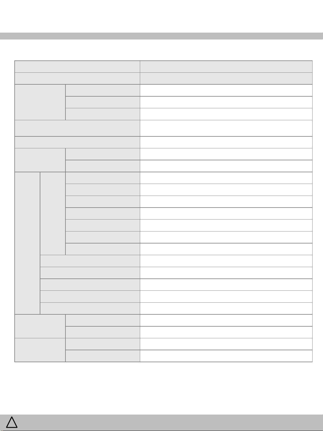
2. Specifications
Model Name 111.7550****, 111.7503****
Factory Model Name RFP71KE******-****, RFP71KD******-****
Volume
AHAM 2008
(Cu ft.)
(Width * Depth * Height)
Weight
(Kg)
Comp
C
O
O
L
I
N
G
Refrigerant R600a
Quantity 77g
Total 25.5
Freezer 7.8
Refrigerator 17.7
External Dimension
Rated Voltage 115~120V (60Hz)
Net 138
Gross (w/ Package) 151
Model NC4EVA5ALM (SAMSUNG)
Motor Type Inverter Driver
Motor Protection Running Capacitor Starting Device Type Inverter Driver
Starting Device Controller Unit (Inverter) ‘-
35.98 “ x 69.81” x 33.79” (w/o Handle)
WARNING
!
Evaporator Fin Type
Condenser Fan Cooling System
Dryer Molecular Sieve XH-9
Freezer On Right Front Side of Freezer Wall
Door Switch
Refrigerator In Top Cover Hinge
Freezer 5-LED
Lamp
Refrigerator 18-LED
To avoid risk of electrical shock that can cause death or severe personal injury,
disconnect unit from power before servicing unless tests require power.
5
/ 79
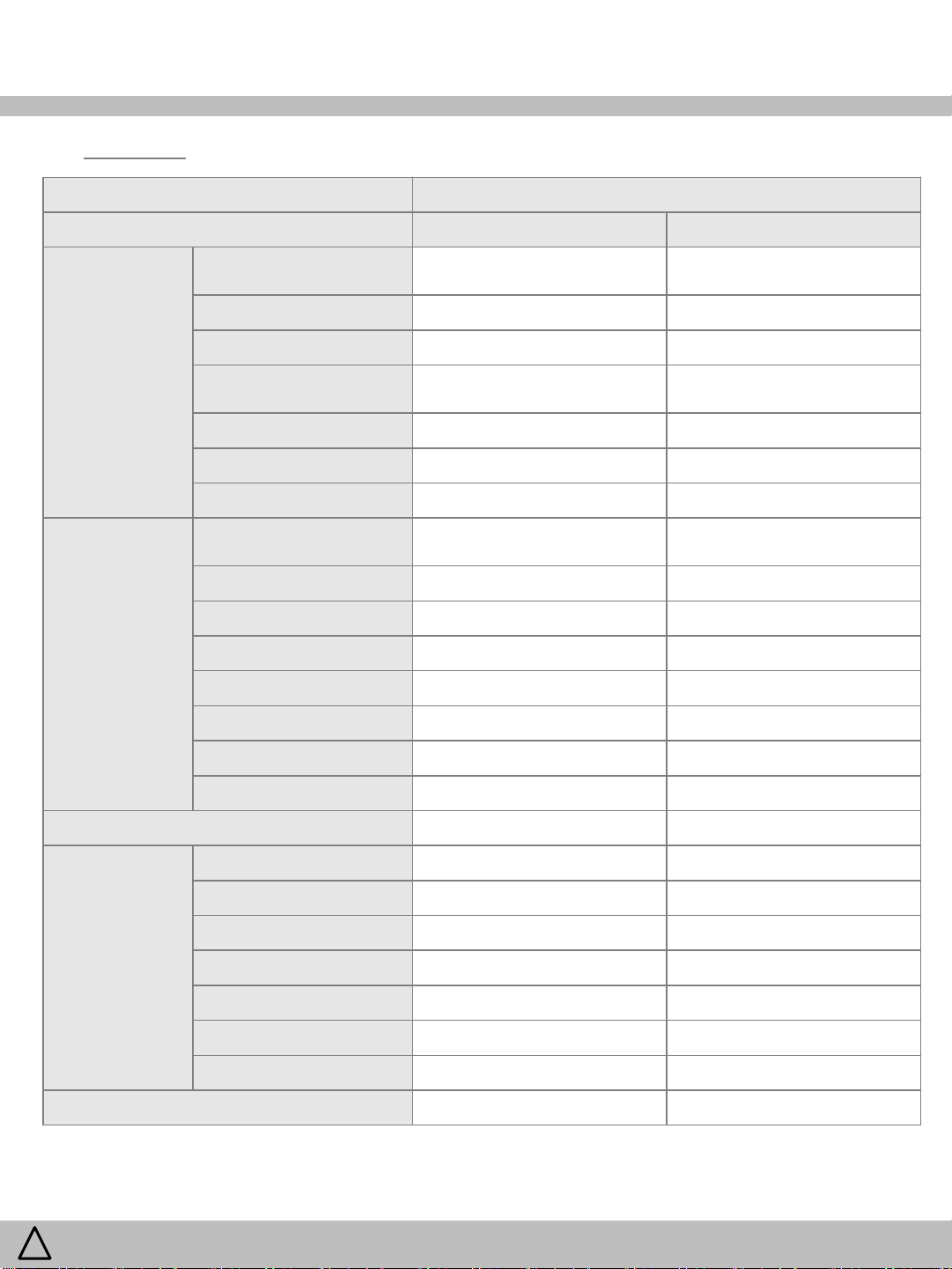
2. Specifications
(continued)
Model Name 111.7550****, 111.7503****
Factory Model Name RFP71KE******-**** RFP71KD******-****
Sensor
Heater
Defrost
Freezer In Louver Assembly
Refrigerator In Multi Flow Duct Assembly
RT
Icemaker Room Temp. In Fixture Geared Motor Assembly
Pantry Drawer Temp. In Multi Flow Duct Assembly
Water Flow In Valve Water Assembly
Freezer Eva.
Icemaker Eva. AC120V / 40W / 360Ω / Sheath
Division AC115V / 6W / 2028 ~ 2380Ω
Water Tank N/A
Dispenser Ice Flap N/A
R Motor behind Eva N/A
Icemaker Water Hose No Service Part
In Evaporator Assembly,
In Icemaker Evaporator Assembly
Between Top Cabinet and Top
Cover Hinge
AC120V / 380W / 35 ~ 41Ω /
Sheath
WARNING
!
Motor
Icemaker Room Heater N/A
Fuse Temp (Defrost)
Freezer Fan DC12V / DREP9020LJ
Refrigerator Fan DC12V / DREP9020LL
Condenser Fan DC13V / D4612AAA28
Dispenser Ice Shut DC 12V / STAB040D01
Ice Crusher 120V / 60Hz / ISG-3240DED
Ice Type Selector DC12V / STAB04D01
Ice Maker Fan DC12V / ODM-016F-57A
Damper DC12V / DU24-113 / 1pcs N/A
To avoid risk of electrical shock that can cause death or severe personal injury,
disconnect unit from power before servicing unless tests require power.
AC250V , 10A , 77℃
6
/ 79
3. Sensor / Voltage
(Table of sensor resistance and measured voltage)
R, Pantry, Ice Maker, F Defrost, R Defrost, I/M Defrost, RT SENSOR
Temp(℉) Temp(℃) Resistance(kΩ) DC Volts Temp(℉) Temp(℃) Resistance(kΩ) DC Volts
-22.0 -30.0 129.30 4.02 32.9 0.5 29.34 2.42
-21.1 -29.5 125.90 4.00 33.8 1.0 28.71 2.39
-20.2 -29.0 122.50 3.98 34.7 1.5 28.08 2.36
-19.3 -28.5 119.30 3.96 35.6 2.0 27.47 2.33
-18.4 -28.0 116.20 3.94 36.5 2.5 26.88 2.31
-17.5 -27.5 113.20 3.91 37.4 3.0 26.30 2.28
-16.6 -27.0 110.20 3.89 38.3 3.5 25.74 2.25
-15.7 -26.5 107.40 3.87 39.2 4.0 25.19 2.23
-14.8 -26.0 101.60 3.82 40.1 4.5 24.65 2.20
-13.9 -25.5 101.90 3.82 41.0 5.0 24.13 2.17
-13.0 -25.0 99.30 3.80 41.9 5.5 23.62 2.15
-12.1 -24.5 96.70 3.77 42.8 6.0 23.12 2.12
-11.2 -24.0 94.30 3.75 43.7 6.5 22.63 2.09
-10.3 -23.5 91.90 3.73 44.6 7.0 22.15 2.07
-9.4 -23.0 89.60 3.70 45.5 7.5 21.69 2.04
-8.5 -22.5 87.30 3.68 46.4 8.0 21.24 2.02
-7.6 -22.0 85.10 3.65 47.3 8.5 20.80 1.99
-6.7 -21.5 83.00 3.63 48.2 9.0 20.36 1.97
-5.8 -21.0 80.90 3.60 49.1 9.5 19.94 1.94
-4.9 -20.5 78.90 3.58 50.0 10.0 19.53 1.92
-4.0 -20.0 76.90 3.55 50.9 10.5 19.13 1.89
-3.1 -19.5 75.00 3.52 51.8 11.0 18.74 1.87
-2.2 -19.0 78.20 3.57 52.7 11.5 18.35 1.84
-1.3 -18.5 71.40 3.47 53.6 12.0 17.98 1.82
-0.4 -18.0 69.60 3.45 54.5 12.5 17.61 1.80
0.5 -17.5 67.90 3.42 55.4 13.0 17.26 1.77
1.4 -17.0 66.30 3.39 56.3 13.5 16.91 1.75
2.3 -16.5 64.70 3.37 57.2 14.0 16.37 1.71
3.2 -16.0 63.10 3.34 58.1 14.5 16.26 1.71
4.1 -15.5 61.60 3.31 59.0 15.0 15.91 1.68
5.0 -15.0 60.10 3.28 59.9 15.5 15.59 1.66
5.9 -14.5 58.60 3.26 60.8 16.0 15.28 1.64
6.8 -14.0 57.20 3.23 61.7 16.5 14.98 1.61
7.7 -13.5 55.90 3.20 62.6 17.0 14.66 1.59
8.6 -13.0 54.60 3.17 63.5 17.5 14.39 1.57
9.5 -12.5 53.30 3.15 64.4 18.0 14.10 1.55
10.4 -12.0 52.00 3.12 65.3 18.5 13.83 1.53
11.3 -11.5 50.80 3.09 66.2 19.0 13.56 1.51
12.2 -11.0 49.60 3.06 67.1 19.5 13.29 1.49
13.1 -10.5 48.70 3.04 68.0 20.0 13.03 1.47
14.0 -10.0 47.30 3.01 68.9 20.5 12.78 1.45
14.9 -9.5 46.20 2.98 69.8 21.0 12.53 1.43
15.8 -9.0 45.10 2.95 70.7 21.5 12.29 1.41
16.7 -8.5 44.10 2.92 71.6 22.0 12.05 1.39
17.6 -8.0 43.10 2.89 72.5 22.5 11.82 1.37
18.5 -7.5 42.10 2.86 73.4 23.0 11.60 1.35
19.4 -7.0 41.10 2.83 74.3 23.5 11.37 1.33
20.3 -6.5 40.30 2.81 75.2 24.0 11.16 1.31
21.2 -6.0 39.30 2.78 76.1 24.5 10.95 1.29
22.1 -5.5 37.90 2.73 77.0 25.0 10.74 1.27
23.0 -5.0 37.50 2.72 77.9 25.5 10.54 1.26
23.9 -4.5 36.70 2.69 78.8 26.0 10.34 1.24
24.8 -4.0 35.80 2.66 79.7 26.5 10.14 1.22
25.7 -3.5 35.00 2.64 80.6 27.0 9.945 1.20
26.6 -3.0 34.30 2.61 81.5 27.5 9.768 1.19
27.5 -2.5 33.50 2.58 82.4 28.0 9.586 1.17
28.4 -2.0 32.70 2.55 83.3 28.5 9.408 1.15
29.3 -1.5 32.00 2.52 84.2 29.0 9.234 1.14
30.2 -1.0 31.30 2.50 85.1 29.5 9.063 1.12
31.1 -0.5 30.60 2.47 86.0 30.0 8.896 1.10
32.0 0.0 30.00 2.44
WARNING
!
To avoid risk of electrical shock that can cause death or severe personal injury,
disconnect unit from power before servicing unless tests require power.
7
/ 79
3. Sensor / Voltage
(Table of sensor resistance and measured voltage)
F Sensor
Temp(℉) Temp(℃) Resistance(kΩ) DC Volts Temp(℉) Temp(℃) Resistance(kΩ) DC Volts
-22.0 -30.0 39.652 3.04 32.9 0.5 7.692 1.16
-21.1 -29.5 38.495 3.01 33.8 1.0 7.508 1.14
-20.2 -29.0 37.375 2.97 34.7 1.5 7.328 1.12
-19.3 -28.5 36.291 2.94 35.6 2.0 7.153 1.10
-18.4 -28.0 35.242 2.90 36.5 2.5 6.983 1.07
-17.5 -27.5 34.227 2.87 37.4 3.0 6.818 1.05
-16.6 -27.0 33.240 2.83 38.3 3.5 6.656 1.03
-15.7 -26.5 31.372 2.76 39.2 4.0 6.500 1.02
-14.8 -26.0 30.926 2.74 40.1 4.5 6.347 1.00
-13.9 -25.5 30.480 2.72 41.0 5.0 6.198 0.98
-13.0 -25.0 29.616 2.69 41.9 5.5 6.054 0.96
-12.1 -24.5 28.780 2.65 42.8 6.0 5.913 0.94
-11.2 -24.0 27.970 2.62 43.7 6.5 5.776 0.92
-10.3 -23.5 27.185 2.58 44.6 7.0 5.642 0.91
-9.4 -23.0 26.425 2.54 45.5 7.5 5.512 0.89
-8.5 -22.5 25.686 2.51 46.4 8.0 5.386 0.87
-7.6 -22.0 24.974 2.47 47.3 8.5 5.262 0.86
-6.7 -21.5 24.283 2.44 48.2 9.0 5.142 0.84
-5.8 -21.0 23.612 2.40 49.1 9.5 5.025 0.82
-4.9 -20.5 22.963 2.37 50.0 10.0 4.911 0.81
-4.0 -20.0 22.333 2.33 50.9 10.5 4.800 0.79
-3.1 -19.5 21.722 2.30 51.8 11.0 4.691 0.78
-2.2 -19.0 21.130 2.27 52.7 11.5 4.586 0.76
-1.3 -18.5 20.557 2.23 53.6 12.0 4.483 0.75
-0.4 -18.0 20.000 2.20 54.5 12.5 4.383 0.73
0.5 -17.5 19.460 2.16 55.4 13.0 4.285 0.72
1.4 -17.0 18.937 2.13 56.3 13.5 4.190 0.71
2.3 -16.5 18.429 2.10 57.2 14.0 4.097 0.69
3.2 -16.0 17.937 2.06 58.1 14.5 4.007 0.68
4.1 -15.5 17.459 2.03 59.0 15.0 3.918 0.67
5.0 -15.0 16.995 2.00 59.9 15.5 3.832 0.65
5.9 -14.5 16.545 1.97 60.8 16.0 3.749 0.64
6.8 -14.0 16.109 1.94 61.7 16.5 3.668 0.63
7.7 -13.5 15.635 1.90 62.6 17.0 3.587 0.62
8.6 -13.0 15.274 1.87 63.5 17.5 3.509 0.60
9.5 -12.5 14.875 1.84 64.4 18.0 3.433 0.59
10.4 -12.0 14.487 1.81 65.3 18.5 3.350 0.58
11.3 -11.5 14.111 1.78 66.2 19.0 3.287 0.57
12.2 -11.0 13.746 1.75 67.1 19.5 3.217 0.56
13.1 -10.5 13.391 1.72 68.0 20.0 3.148 0.55
14.0 -10.0 13.047 1.69 68.9 20.5 3.081 0.54
14.9 -9.5 14.712 1.83 69.8 21.0 3.015 0.53
15.8 -9.0 12.387 1.63 70.7 21.5 2.927 0.51
16.7 -8.5 12.072 1.61 71.6 22.0 2.839 0.50
17.6 -8.0 11.765 1.58 72.5 22.5 2.829 0.50
18.5 -7.5 11.467 1.55 73.4 23.0 2.769 0.49
19.4 -7.0 11.176 1.52 74.3 23.5 2.711 0.48
20.3 -6.5 10.897 1.50 75.2 24.0 2.655 0.47
21.2 -6.0 10.624 1.47 76.1 24.5 2.600 0.46
22.1 -5.5 10.358 1.44 77.0 25.0 2.546 0.45
23.0 -5.0 10.109 1.42 77.9 25.5 2.493 0.45
23.9 -4.5 9.849 1.39 78.8 26.0 2.442 0.44
24.8 -4.0 9.605 1.37 79.7 26.5 2.392 0.43
25.7 -3.5 9.368 1.34 80.6 27.0 2.343 0.42
26.6 -3.0 9.138 1.32 81.5 27.5 2.295 0.41
27.5 -2.5 8.913 1.30 82.4 28.0 2.246 0.40
28.4 -2.0 8.696 1.27 83.3 28.5 2.202 0.40
29.3 -1.5 8.484 1.25 84.2 29.0 2.158 0.39
30.2 -1.0 8.277 1.23 85.1 29.5 2.114 0.38
31.1 -0.5 8.077 1.20 86.0 30.0 2.072 0.38
32.0 0.0 7.882 1.18
WARNING
!
To avoid risk of electrical shock that can cause death or severe personal injury,
disconnect unit from power before servicing unless tests require power.
8
/ 79
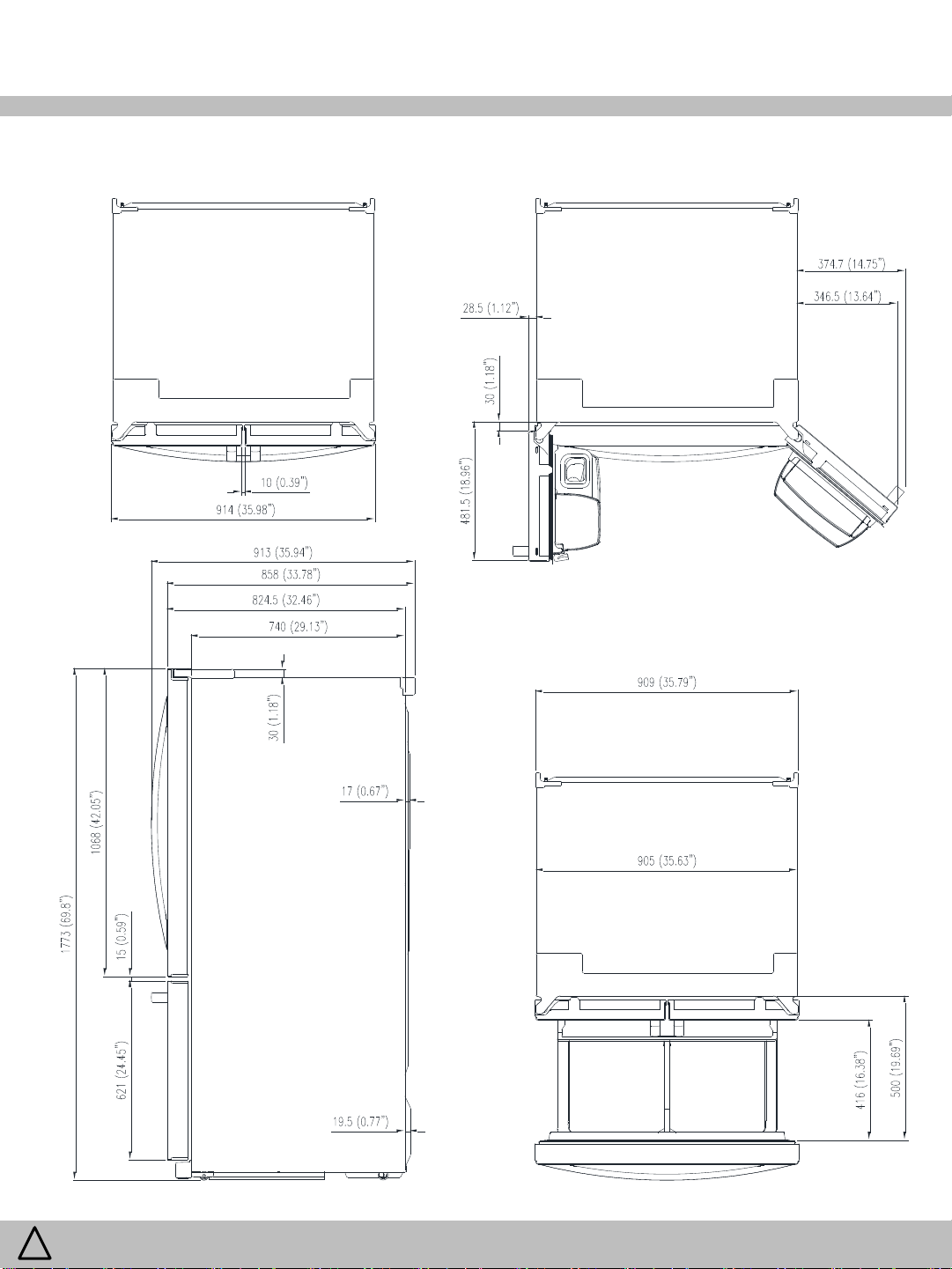
4. External Dimensions
WARNING
!
To avoid risk of electrical shock that can cause death or severe personal injury,
disconnect unit from power before servicing unless tests require power.
9
/ 79
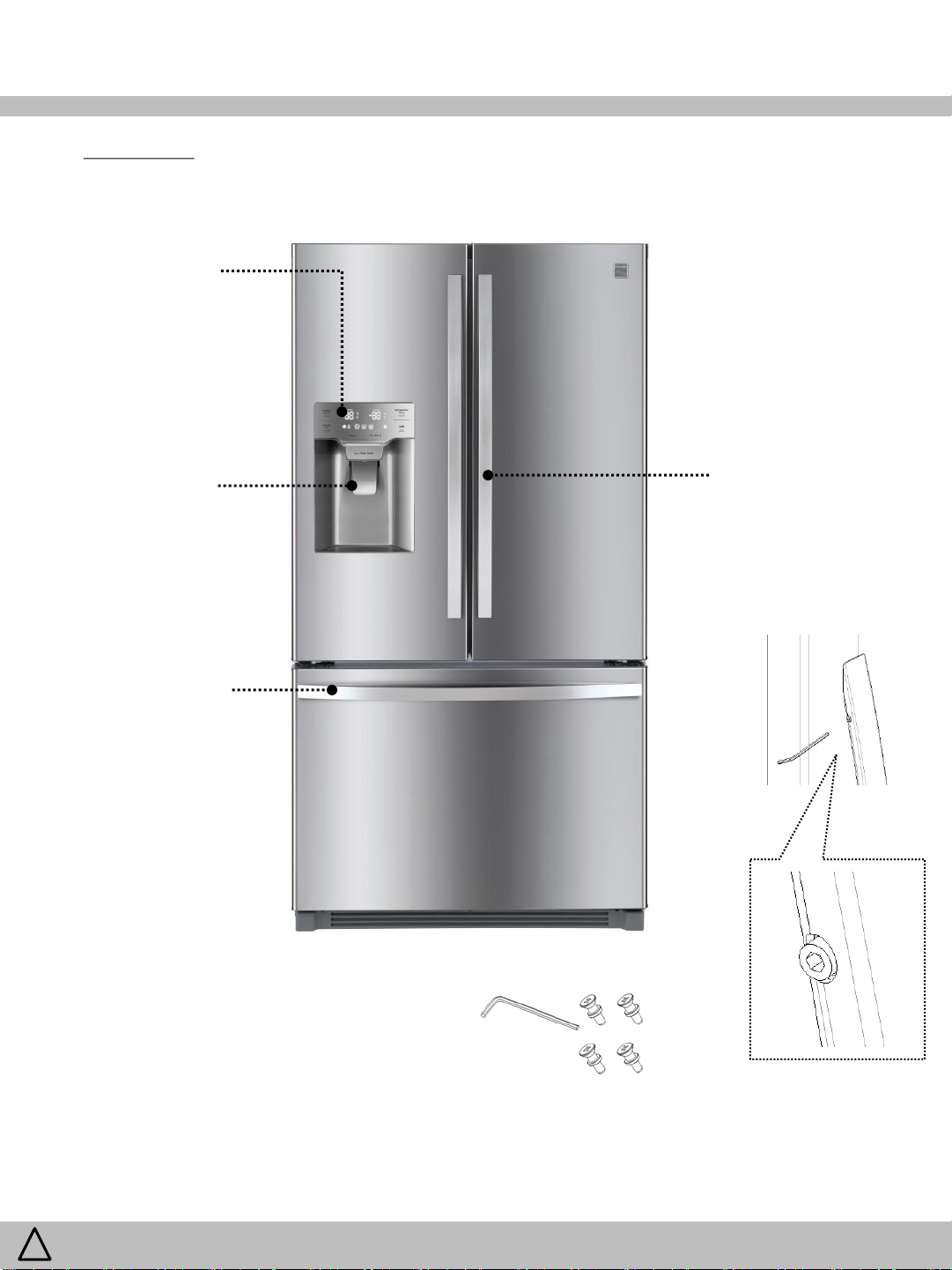
5. Features
5-1. Exterior
Front Control
Panel
LED, Touch
Water and Ice
Dispenser
1 Levers
Freezer Handle
Sticker written “F”
inside handle for
correct assembly
Refrigerator Handle
Sticker written “R”
inside handles for
correct assembly
WARNING
!
Included Parts
Hex Wrench(2.5mm) in User Manual Bag, Standoff
Screws on doors
To avoid risk of electrical shock that can cause death or severe personal injury,
disconnect unit from power before servicing unless tests require power.
10
/ 79
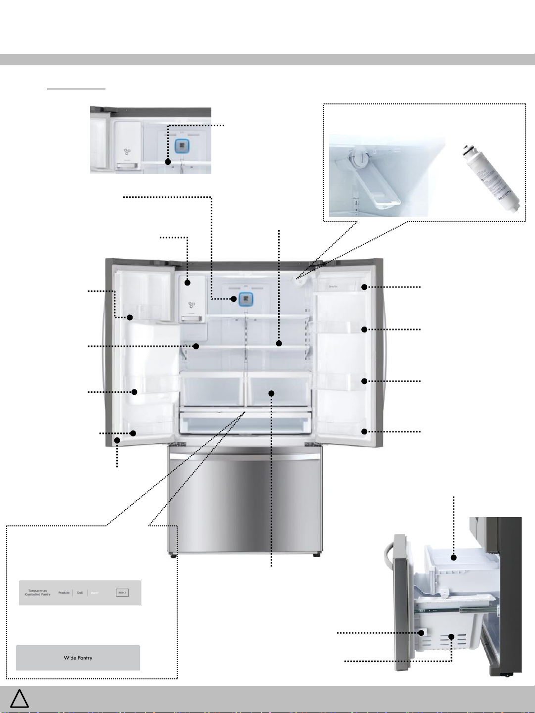
5. Features
5-2. Interior
Air Filter Cover
Icemaker Compartment
Icemaker and Ice Bin
Water Filter Filter Cover
Foldable Shelf
fixed by magnet
after folding
Slid Away Split
Shelf
Dispenser
Bin
Fixed
Shelves
Adjustable,
Spill proof
Small Bin
Fixed
Bottom Bin
Mullion Bar
- Temperature Controlled
Pantry Drawer(RFP71KE*)
3 Steps Select Produce / Deli / Meat
Dairy Bin
Utility Bin
Adjustable
Gallon Bin
Adjustable
Bottom Bin
Adjustable
Auto Pull Out Drawer
Humidity Controlled
Crisper
Vegetable & Fruit
- Wide Pantry
Drawer(RFP71KD*)
WARNING
!
To avoid risk of electrical shock that can cause death or severe personal injury,
disconnect unit from power before servicing unless tests require power.
Button Door Switch
Freezer Base Drawer
11
/ 79
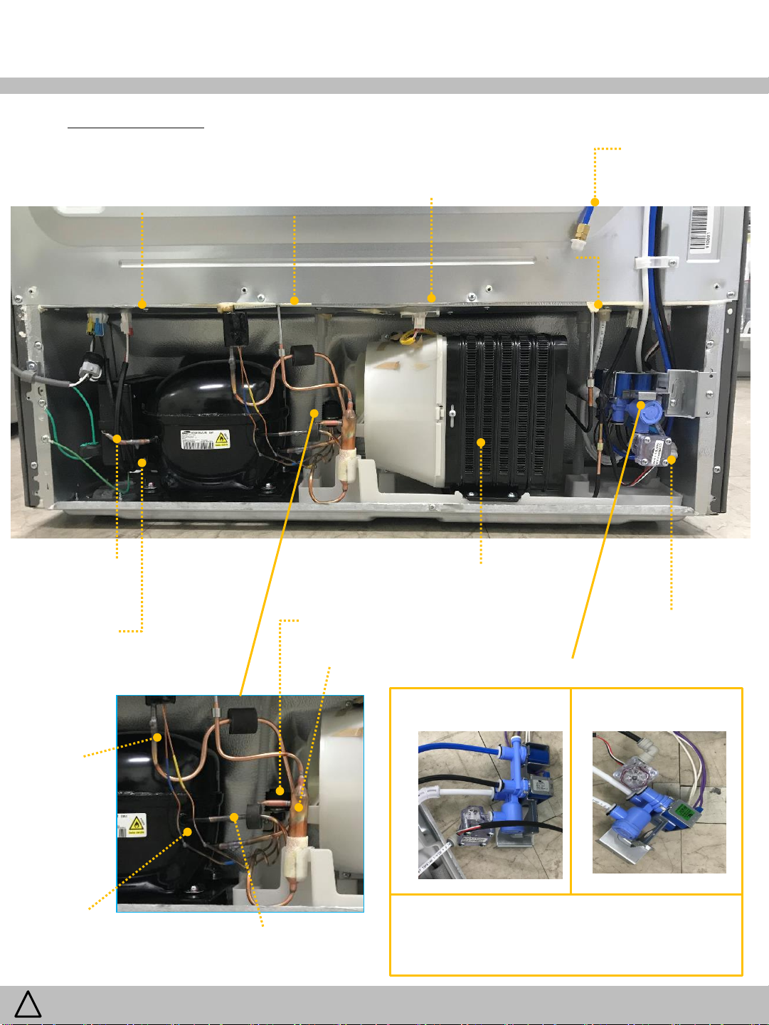
5. Features
5-3. Machine Room
Inverter Controller
Signal Connector
Hot Pipe
(Outlet)
Condenser Fan
Connector(front)
Step Valve
Connector(back)
Water Filter Inlet
1/4 “ Tube)
Hot Pipe
(Inlet)
Process Part
in Compressor
Inverter
Controller
Pipe Suction
Conn
Capillary Tube
- Blue : F Eva.
- Yellow : Ice Maker Eva.
Step Valve
Dryer
Pipe Condenser Conn
(Discharge Part)
Condenser
Flow Sensor
in Valve Water
Valve Water
MODEL : RFP71KE** MODEL : RFP71KD**
①
④
①
③
②
① Black(1/4”) – Ice Maker Tube(R room)
② White(1/4”) – Water Filter Outlet
③ White(5/16”) – Water Tank Inlet
④ Blue(1/4”) - Ice Maker tube(F room)
③
②
WARNING
!
To avoid risk of electrical shock that can cause death or severe personal injury,
disconnect unit from power before servicing unless tests require power.
12
/ 79
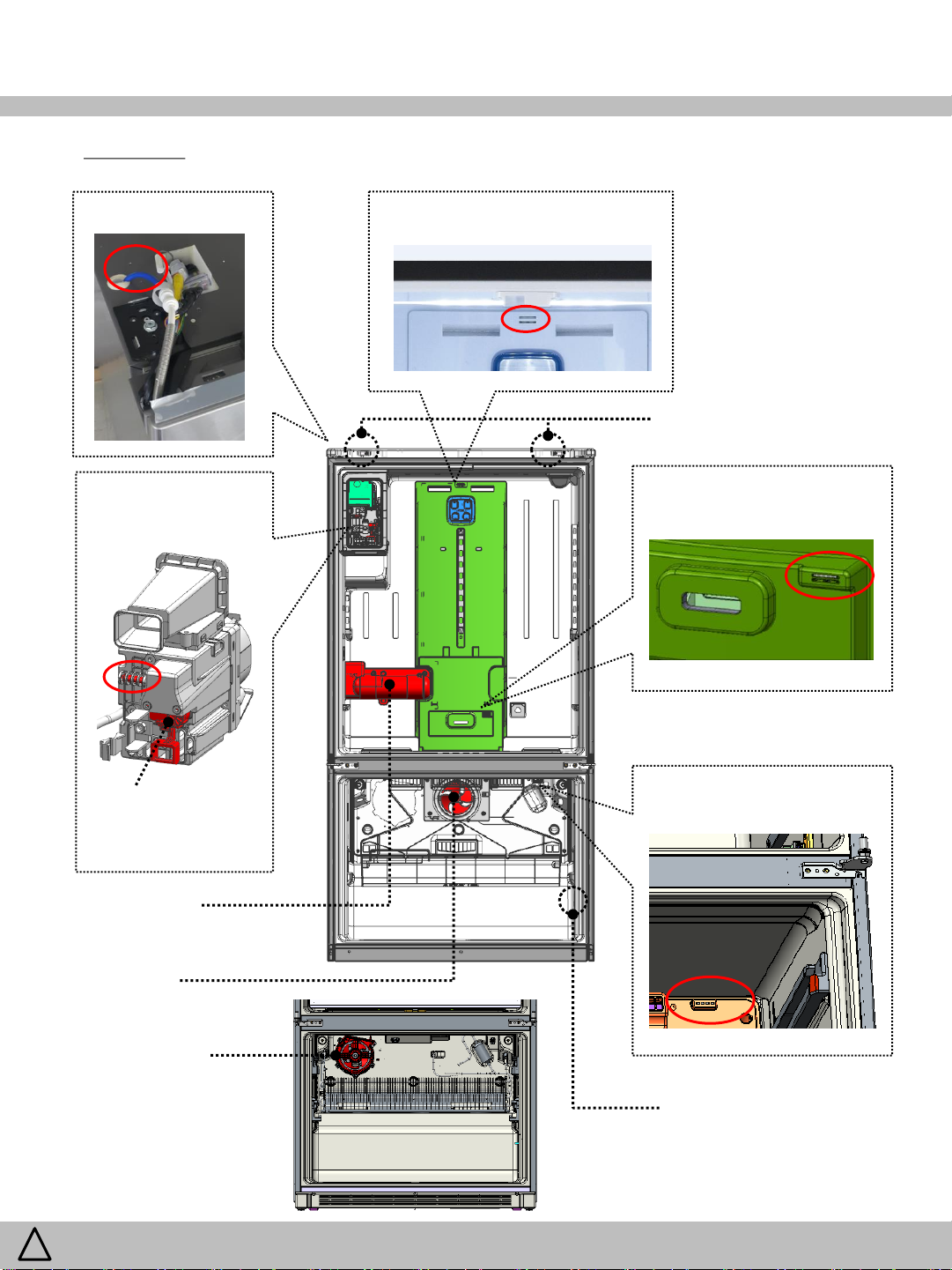
5. Features
5-4. Others
RT Sensor Refrigerator Sensor
Refrigerator Door Switches
Icemaker
Room Sensor
Ice Type
(Cubed/Crushed)
Selector
Water Tank
Assembly
Freezer
Fan Motor
Pantry
Drawer Sensor
Freezer Sensor
WARNING
!
Refrigerator
Fan Motor
To avoid risk of electrical shock that can cause death or severe personal injury,
disconnect unit from power before servicing unless tests require power.
Freezer Door Switch
13
/ 79
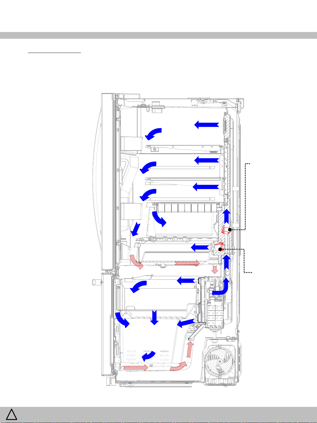
6. Flow Diagram
6-1. Cold Air Flow
Refrigerator
Compartment
Damper
Control Air of
Refrigerator
WARNING
!
Freezer
Compartment
To avoid risk of electrical shock that can cause death or severe personal injury,
disconnect unit from power before servicing unless tests require power.
Damper
Control Air of Pantry
Drawer
(RFP71KE*)
14
/ 79

6. Flow Diagram
6-2. Water Flow
RFP71KE*
Main
Water
RFP71KD*
Main
Water
Water
Filter
Water
Filter
□ Water Supply Pressure must be :
Flow
Sensor
Water
Valve
Water
Valve
Water
Tank
Flow
Sensor
Water
Tank
Icemaker
(R Room)
Icemaker
(F Room)
Water
Dispenser
Icemaker
(R Room)
Water
Dispenser
Min 30psi (207kPa, 2.1kgf/㎠)
Max 125psi (862Kpa, 8.8kgf/㎠)
※ If the water pressure exceeds 125psi,
a pressure reducing valve must be installed.
※ If the water pressure is under 30psi,
a booster pump must be installed.
WARNING
!
To avoid risk of electrical shock that can cause death or severe personal injury,
disconnect unit from power before servicing unless tests require power.
15
/ 79
6. Flow Diagram
6-3. Refrigerant Flow and Welding Point
PIPE SVC(Discharge)
COMPRESSOR
PIPE DEL
PIPE HOT
CONDENSER
DRYER AS
STEP VALVE
CAPILLARY TUBE
(BLUE)
EVAPORATOR
(F Room)
CAPILLARY TUBE
(YELLOW)
EVAPORATOR
(Ice maker)
SYMBOL METHOD POINTS
Copper Welding (Ag 3%) 11
Lokring 3
You can force open all the step valve for 2
evaporators by following the next steps:
1. Lock inner PCB
2. While pressing the “Refrigerator Temp”
and “Freezer Temp” buttons, then
press “Light” button 5 times
High Temperature
High Pressure
Refrigerant flow system :
When the refrigerator valve is open, the
refrigerant flows through the icemaker and
freezer compartment.
When the icemaker valve is open, the
refrigerant flows through the freezer and
icemaker compartment.
When the freezer valve is open, the
refrigerant flows through the freezer
compartment only.
There is no way to force open each
individual valve.
Low Temperature
Low Pressure
WARNING
!
PIPE SUC
PIPE SUC CONN
COMPRESSOR
To avoid risk of electrical shock that can cause death or severe personal injury,
disconnect unit from power before servicing unless tests require power.
16
/ 79
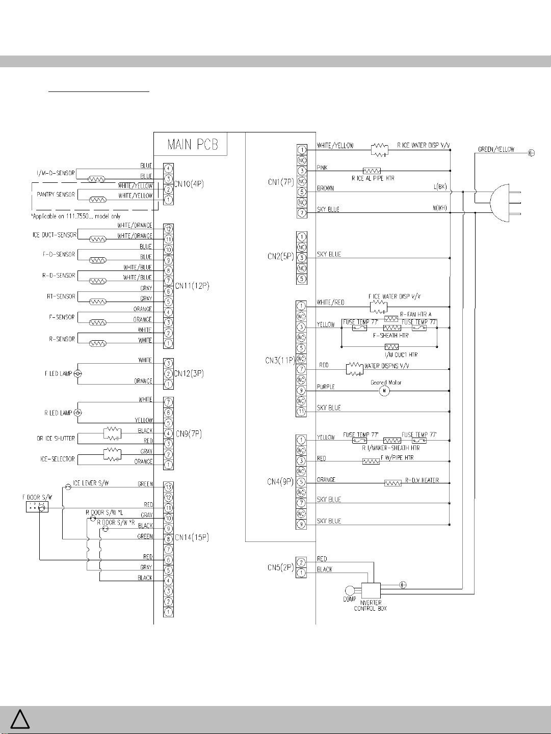
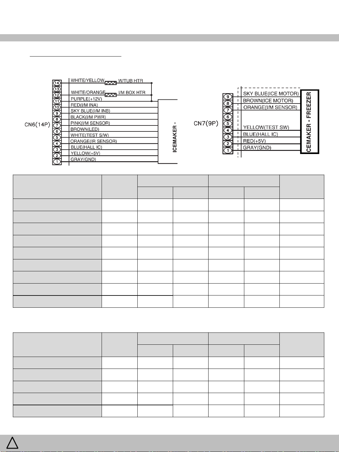
7. Wiring Diagram
7-1. Total View(1/2)
WARNING
!
To avoid risk of electrical shock that can cause death or severe personal injury,
disconnect unit from power before servicing unless tests require power.
17
/ 79
7. Wiring Diagram
7-1. Total View(2/2)
WARNING
!
To avoid risk of electrical shock that can cause death or severe personal injury,
disconnect unit from power before servicing unless tests require power.
18
/ 79

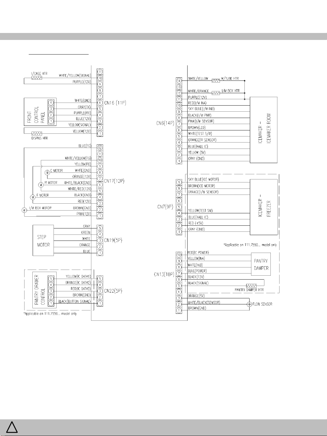
7. Wiring Diagram
7-2. Part View – Sensors
CN11
CN10
7-3. Part View – Eva Heater (SHEATH HTR)
CN4
CN3
WARNING
!
To avoid risk of electrical shock that can cause death or severe personal injury,
disconnect unit from power before servicing unless tests require power.
19
/ 79
7. Wiring Diagram
5 & 10
8 & 13
6 & 11
4 & 9
1 & 2
Frequency (Compressor Power
Consumption
the
7-4. Dispenser, DV(Mullion Bar), I/CASE Heater Operation
7-4-1. The dispenser heater is always on.
7-4-2. The DV heater is always on and located Between refrigerator doors.
7-4-3. The I/CASE heater cycles which is located inside the icemaker helps to remove residual
ice from the ice case.
The heater turns on when the temperature reaches 21.2°F(-6°C) on and turns off
when the temperature reaches 28.4°F(-2°C)
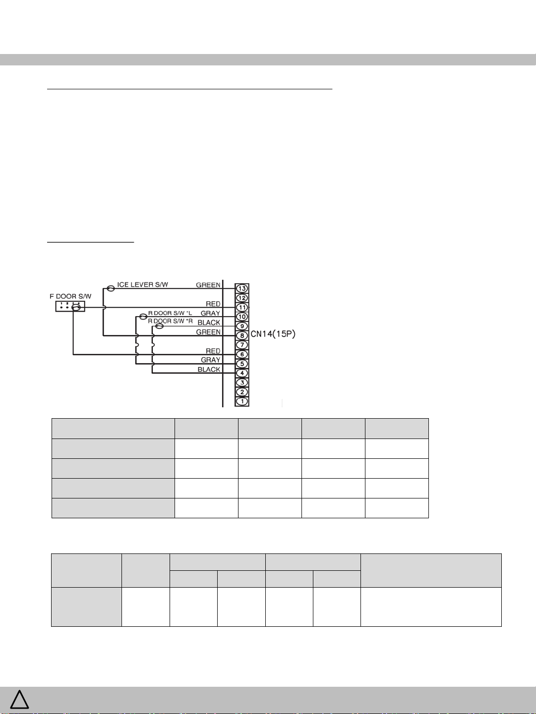
7-5. Other voltage
7-5-1. CN 14 (Switch)
Item Pin No. Open(On) Close(Off)
R DOOR S/W L
ICE LEVER S/W
F DOOR S/W
R DOOR S/W R
7-5-2. CN 5 (Compressor Inverter)
Item Pin No
!
Comp RPM
WARNING
To avoid risk of electrical shock that can cause death or severe personal injury,
disconnect unit from power before servicing unless tests require power.
0V 5V
0V 5V
5V 0V
0V 5V
On Off
V Hz V Hz
3.3 50~125
6.5 -
비고
main PCB
Remarks
) Feedback to
20
/ 79
7. Wiring Diagram
Water Tube
1 & 14
I/M
N/A
I/M Stepping
1 & 9,
Bi-Directional
Icemaker Power
1 & 8
Icemaker LED
1 &
Icemaker
1 & 7
Icemaker Test
1 & 5
Start Position Check Sensor
1 & 4
Ice Bucket Full
1 & 4
I/M Stepping
1 & 8, 9
Icemaker
1 & 7
Icemaker Test
1 & 4
Start Position Check Sensor
1 & 3
Ice Bucket Full
1 & 5
7-5. Other voltage (continued)
7-5-3. CN 6 (Icemaker in the ice room)
Item Pin No
Heater
Box Heater
Motor
Temp. Sensor
Switch
Check Sensor
0
N/A N/A N/A N/A
10 2.5
5
6 0
0
0
5
(Start)
On Off
V Hz V Hz
12
5
0
10
(Full)
5
5
0
7-5-4. CN 7 (Icemaker in the freezer compartment) ※ 111.7550… model only
Item Pin No
On Off
V Hz V Hz
Remarks
Sensor Table
Remarks
Motor
Temp. Sensor
Switch
Check Sensor
!
WARNING
To avoid risk of electrical shock that can cause death or severe personal injury,
disconnect unit from power before servicing unless tests require power.
2.5 5
0 5
0(Start)
5(Full)
5
0
Sensor Table
21
/ 79

7. Wiring Diagram
Damper
5 & 6
Damper Signal
1 & 7, 8, 9, 10
Step
5 & 1, 2, 3, 4
0~12
swing
1 & 2, 3, 4, 5
2 &, 3, 4, 5
3 & 4, 5
4 & 5
Pin
Color of lead wire
7-5. Other voltage (continued)
7-5-5. CN 13 (Damper)
Item Pin No
On Off
V Hz V Hz
Heater
0 - 12 -
6 - 0 -
7-5-6. CN 19 (Step Valve)
Item Pin No
Motor
※ Floating – pins 1, 2, 3, 4 are completed to circuit ground in sequence to operate the step valve
Step Motor
On Off
V Hz V Hz
- 12 -
Following is the correct pin for PCB and step motor pin:
PCB Pin 1 = Step Motor Pin 5
PCB Pin 2 = Step Motor Pin 4
PCB Pin 3 = Step Motor Pin 1
PCB Pin 4 = Step Motor Pin 2
PCB Pin 5 = Step Motor Pin 3
Remarks
Remarks
HOUSING "A"
No. 1 2 3 4 5
!
WARNING
Coil POINT [Ω]
Housing “A”
Pin No.
GRAY BLACK ORANGE BLUE YELLOW
To avoid risk of electrical shock that can cause death or severe personal injury,
disconnect unit from power before servicing unless tests require power.
40±4Ω
80±8Ω
80±8Ω
80±8Ω
22
/ 79

7. Wiring Diagram
1 & 2
2 & 12
7 & 8
3 & 4
4 & 9
5 & 6
6 & 10
7-5. Other voltage (continued)
7-5-7. CN 17 (Fan Motor)
Item Pin No
I/M BOX MOTOR
I/M BOX MOTOR
(Feedback signal)
C MOTOR
F MOTOR
F MOTOR
(Feedback signal)
R MOTOR
R MOTOR
(Feedback signal)
On Off
V Hz V Hz
12 ~ 14 - 0 -
12 ~ 14 - 0 -
12 ~ 14 - 0 -
12 ~ 14 - 0 -
5V Pulse,
Duty 50%
5V Pulse,
Duty 50%
5V Pulse,
Duty 50%
65~80 0 0
45~65 0 0
45~65 0 0
비고
Frequency
fluctuation
Frequency
fluctuation
Frequency
fluctuation
!
WARNING
To avoid risk of electrical shock that can cause death or severe personal injury,
disconnect unit from power before servicing unless tests require power.
23
/ 79

8. Operation and Functions
8-1. How to Use Control Panel
1 2
ⓕ
5
8
ⓐ
3 4
ⓑ
Button Item Display Description
ⓕ
Initial Temperature by power input
-
Freezer Temperature
Freezer Accela Chill Function
88 LED
88 LED
LED ①
Freezer : 0ºF / Refrigerator : 37ºF / Pantry room(optional) : “Produce”
ºF : 0 → -2 → -4 → -6 → -8(Coldest) → 6 → 4 → 2 → (repeat)
℃ : -18 → -19 → -20 → -21 → -22(Coldest) → -15 → -16 → -17 → (repeat)
□ How to Start : Press and hold this button for 3sec.
□ How to Proceed : the icon LED ON, Coldest Temp for 3000min
□ How to End : Time Limit or Any press for changing Temp or Power Rest
7
Button LED
ⓡ
ⓓ
6
ⓒ
ⓡ
ⓓ →
ⓕⓡ
ⓐ
ⓑ
ⓒ
ⓑⓒ
ⓓ
WARNING
!
Refrigerator Temperature
Refrigerator Accela Chill Function
Switch Temperature Unit ºF ↔ ℃
“Accela Ice” Function
Filter Reset
Select Cubed Ice
Select Crushed Ice
Icemaker off
Turn Dispenser Lamp On
Lock Control Function
To avoid risk of electrical shock that can cause death or severe personal injury,
disconnect unit from power before servicing unless tests require power.
88 LED
LED ②
ºF : 37 → 35 → 33(Coldest) → 45 → 43 → 41 → 39→ (repeat)
℃ : 3 → 2 → 1(Coldest) → 7 → 6 → 5 → 4→ (repeat)
□ How to Start : Press and hold this button 3sec.
□ How to Proceed : the icon LED ON, Coldest Temp for 360min
□ How to End : Time Limit or Any press for changing Temp or Power Rest
LED In lock mode, press and hold ⓕ and ⓡ buttons at the same time for 5sec
LED ③
LED ④
LED ⑦
LED ⑧
The icon LED On, Quick ice cube production mode for 24hr
If no water comes into the icemaker for 6hr, the operation is canceled.
Press and hold "Accela Ice” button for 3sec, “Replace Filter” icon LED OFF
※ After about 6 months from power on or Filter Reset, the icon LED ON.
The icon LED ON;
The cubed/crushed ice comes out by pressing the dispenser lever.
⑤ Press and hold ⓑ and ⓒ buttons for 3sec at the same time.
-
⑥
Press the “Light” button or push any dispenser lever.
Press and hold ⓓ button 3sec to stop operation of different buttons.
The ice or water dispenser does not work during lock mode.
24
/ 79

8. Operation and Functions
8-1. How to Use Control Panel (continued)
1 2
ⓕ
5
8
ⓐ
3 4
ⓑ
Button Item Display Description
ⓓ →
ⓐⓕⓡ
ⓓ →
ⓕⓡ
Service Mode
(Error Display)
Forced Defrosting
88 LED
-
□ How to Start : In lock mode, press ⓐ 5 times, while pushing ⓕ & ⓡ at once
□ How to Proceed : operating state values (ex : error codes) are displayed
※ Error display is skipped if no error.
□ How to End : Press “Light” button 1 time or No input for 4min.
□ How to Start : In lock mode, press ⓡ 5 times, while pushing ⓕ
□ How to Proceed : Heater is on regardless of F/R Defrost Sensor for first 30sec.
□ How to End : Same as normal defrosting or Power Rest
7
Button LED
ⓡ
ⓓ
6
ⓒ
ⓓ →
ⓐⓓ
ⓓ →
ⓐⓡⓓ
ⓓ →
ⓕⓡⓓ
Changing Sensor ON/OFF
Temp (for Service)
Showroom Mode
(Cooling Off)
(Demo Mode)
Forced Comp On Mode
(use this mode, when you
recharge refrigerant.)
88 LED
LED
□ How to Start : In lock mode, press ⓓ 5 times, while pushing ⓐ
□ How to Proceed :
Default Value Display F 88 LED “00” R 88 LED “00”
Value “01” = 0.13ºF (0.072℃) 0.18ºF (0.1℃)
Range of Value Change “00 ±30”
= Range of Temp Change 0±3.9ºF (0±2.16℃) 0±5.4ºF (0±3℃)
Control Button to be Warmer
Control Button to be Colder
□ How to End : No input for 10sec
□ If the refrigerator is disconnected from initial power on before 5 days
after setting change, the value is initialized.
□ How to Start : In lock mode, press ⓓ 5 times, while pushing ⓐ & ⓡ at once
□ How to Proceed : All electrical components are OFF
[except] Control Panel sequentially display; Dispenser LED ON;
All dampers open; Fans & interior lamps ON/OFF by door opening.
□ How to End : In lock mode, ⓓ 5 times + ⓐ & ⓡ at once or Power Rest
□ How to Start :In lock mode, press ⓓ 5 times, while pushing ⓕ & ⓡ at once
□ How to Proceed : Compressor operates continuously for 30 hours.
□ How to End : Power reset, or after 30 hours.
Freezer Refrigerator
ⓕ ⓡ
ⓐ ⓓ
WARNING
!
To avoid risk of electrical shock that can cause death or severe personal injury,
disconnect unit from power before servicing unless tests require power.
25
/ 79

8. Operation and Functions
8-2. Service Mode and Error Display
□ How to Start :
Preparation Work INPUT
“Lock” Mode ON
Freezer
Temp
+
Refrigerator
Temp
+
□ How to Proceed :
ºF
• Unit
Press “Freezer Temp” button and the following value is displayed successively.
:
• Unit ℃ : Press “Accela Ice” button and the following value is displayed successively.
Example Display
STEP Content
etc. F 88 R 88 etc.
Operating Time 12 34 12hr 34min ※ reset every 24hr
1
Freezer Sensor Temp - F0 58 ºF -5.8ºF ※ Sensor Open / Short : R 88 = Hi / Lo
2
Refrigerator Sensor Temp r3 92 ºF 39.2ºF ※ Sensor Open / Short : R 88 = Hi / Lo
3
Freezer Defrost(FD) Sensor Temp - d1 39 ºF -13.9ºF ※ Sensor Open / Short : R 88 = Hi / Lo
4
Icemaker Room Defrost Sensor Temp - b0 58 ºF -5.8ºF ※ Sensor Open / Short : R 88 = Hi / Lo
5
Icemaker Sensor Temp
6
in the Icemaker Room
Icemaker Sensor Temp
7
in the Freezer (Dual Icemaker Model)
c0 95 ºF 9.5ºF ※ Sensor Open / Short : R 88 = Hi / Lo
n0 32 ºF 3.2ºF ※ Sensor Open / Short : R 88 = Hi / Lo
Accela
Ice
Description
Icemaker Room(IR) Sensor Temp i1 50 ºF 15ºF ※ Sensor Open / Short : R 88 = Hi / Lo
8
Pantry Drawer Sensor Temp u3 02 ºF 30.2ºF ※ Sensor Open / Short : R 88 = Hi / Lo
9
R Defrost(RD) Sensor Temp - E1 39 ºF -13.9ºF ※ Sensor Open / Short : R 88 = Hi / Lo
10
RT Sensor Temp t7 64 ºF Ambient Temperature : 76.4ºF
11
Filter remaining Life Time 43 17 4,317hr
12
Flow Sensor Pulse Value of the
13
icemaker in the freezer
Flow Sensor Pulse Value of the
14
icemaker in the icemaker Room
Error Code : F Sensor Er F1
15
Error Code : R Sensor Er r1
16
o1 00
P1 00
o100 / P100 (Default value) = 282 pulse
Do not change the default value.
!
(Icemaker is filled a certain amount of water
provided by flow sensor in water valve.)
※ if “Ice Select” button pushed :
ex) P100(default value)→P101→P102→…
→P150(max)→P50(min)→P51→…→P100→(repeat)
The sensor is read as open or shorted.
Check the wiring connections in each part and at Main
PCB.
※ The temperature by display in service mode is shown by sensor. The real temp of the cooling area could be different.
WARNING
!
To avoid risk of electrical shock that can cause death or severe personal injury,
disconnect unit from power before servicing unless tests require power.
26
/ 79

8. Operation and Functions
8-2. Service Mode and Error Display (continued)
STEP Content
Error Code : Icemaker Sensor in the
17
Icemaker Room
Error Code : Icemaker Room Sensor Er i3
18
Error Code : Icemaker Sensor in the freezer Er i2
19
Error Code : Pantry Drawer Sensor Er u1
20
Error Code : F Defrost Sensor Er Fd
21
Error Code : R Defrost Sensor Er rd
22
Error Code : Icemaker Room Defrost sensor Er id
23
Error Code : RT Sensor Er rt
24
Error Code : Cycle Er C1
25
Error Code : F Door Switch Er dF
26
Error Code : R Door Switch Er dr
27
Error Code : F Defrost Heater Er F3
28
Error Code : Icemaker Room Defrost Heater Er r3
29
Error Code : EEPROM Er EP EEPROM read / write error
30
Error Code : Dispenser Lever Time Er ES In case dispenser lever is pressed for over 1min
31
Example Display
etc. F 88 R 88 etc.
Er i1
Description
The sensor is read as open or shorted.
Or Icemaker Heating Error
The sensor is read as open or shorted.
Check the wiring connections in each part and at
Main PCB.
In case compressor works for over 3hr when FD
or RD sensor temp is over 23ºF(-5℃)
Check refrigerant leakage.
In case it senses that door is open for more than
1hr.
Check F/R door or Door Switch.
In case defrosting return is done by time limit of
50 min
Check the Defrost HTR or Defrost sensor .
Error Code : Water Supply Error Er E9 Icemaker water supply error
32
Error Code : Icemaker Error Er EA Flat sensor error in the freezer icemaker
33
Error Code : Flow Sensor Error Er EF The sensor is read as open or shorted.
34
35
Error Code : F Fan Motor RPM Error
36
Error Code : R Fan Motor RPM Error
37
Error Code : I/Maker Fan Motor RPM Error
Mode Display : Forced Defrost Ξ Ξ D2 Forced Defrost
38
Mode Display : Forced Comp ON Ξ Ξ Co Forced Comp ON
39
Er FF Freezer fan motor RPM error
Er rF Refrigerator fan motor RPM error
Er iF Ice maker fan motor RPM error
□ How to End :
Preparation Work INPUT
“Lock” Mode ON
Light
※ Error code will be released automatically when the condition is normal.
WARNING
!
To avoid risk of electrical shock that can cause death or severe personal injury,
disconnect unit from power before servicing unless tests require power.
27
/ 79

8. Operation and Functions
Pantry Damper
Freezer
Refrigerator
Pantry Drawer
Ice
& Step Valve Location
F
R
Defrosting
Showroom Mode
(Demo Mode)
F
(Coldest Temp
for setting time)
(Coldest Temp
for setting time)
(Coldest Temp
for setting time)
R
(Coldest Temp
for setting time)
Accela
for setting time
(only ice making
for setting time
(only ice making
8-3. Compressor, Fan & Damper
On/Off On/Off On/Off - - -
Comp C FAN F FAN R FAN
Output
Icemaker
Room FAN
Temp
Sensor Target
Harvest Condition
Door Open - - - - - -
Door Open - - - - - -
INPUT
Accela Chill
- - - On/Off - -
- - - - Open/Close
Mode Off Off Off Off Off Close
- - - - On/Off -
Off Off
On/Off
On/Off
On only
F Door Open
On/Off
R Door Open
On only
- - -
On only
R Door Open
On/Off
Accela Chill - - -
On
Ice
condition)
■ Compressor will not restart within 6 min after the refrigerator is disconnected from power supply.
□ Fan voltage of control mode : Freezer 13V, Refrigerator 13V, Icemaker Room 13V, Condenser 13V
- - -
- Open/Close
On
condition)
Open
-
8-4. Defrost Mode
□ The defrost mode starts with compressor work time, defrost sensor temp, any error mode, etc.
□ The defrosting return is done by F or R Defrost sensor.
8-5. Forced Defrost Mode
□ How to Start :
Preparation Work INPUT
“Lock” Mode ON
□ How to Proceed and End: Same as normal defrost mode
WARNING
!
To avoid risk of electrical shock that can cause death or severe personal injury,
disconnect unit from power before servicing unless tests require power.
Freezer
Temp
+
Refrigerator
Temp
28
/ 79

8. Operation and Functions
8-6. Icemaker in the Icemaker Room
1) Icemaker Room Temperature Control : by IM Sensor On/Off
• Icemaker Room Temp is controlled by IM Sensor on/off setting value.
• In “Accela Ice” mode, the compress and icemaker room fan will turn on 24hr for Quick Icing.
In case of no icemaker water supply for 6hr, the “Accela Ice” function is canceled.
※
Icemaker
Optics
Sensors
Room Sensor
Icemaker
Room Fan
Ice Type
Selector
Ejector
2) Icemaker System :
start
Ice Making
Ice Harvest
Icemaker Water Supply
Return
Ice Tray
Heater
• Icemaker starts harvest process by sensing tray temp unless ice storage bin is full.
※ When the bin fills to the level of the optics sensors, the icemaker will stop making ice.
• Icemaker has a ejector and a heater for harvest.
• Ice cube surface is melted by the heater installed the ice tray and ice cubes are
swept for the ejector from the ice tray.
• Icemaker is filled a certain amount of water provided by flow sensor in water valve.
• If the water pressure is too low (under flow sensor pulse value 6), the icemaker
will not work.
• To operate the icemaker properly, water pressure of 20~125psi is required.
WARNING
!
※ Water Filter Operation Pressure : 30 ~125psi (207~862kPa, 2.1~8.8kgf/㎠)
※ If the water pressure exceeds 125psi, a pressure reducing valve must be installed.
※ If the water pressure is under 30psi, a booster pump must be installed.
To avoid risk of electrical shock that can cause death or severe personal injury,
disconnect unit from power before servicing unless tests require power.
29
/ 79

8. Operation and Functions
8-6. Icemaker in the Icemaker Room (continued)
3) Icemaker Power OFF :
□ How to Start :
Preparation Work INPUT
“Lock” Mode OFF
□ How to Proceed :
• Display : LED light of Icemaker will turn off. And “Ice off” icon of the control panel will light up.
• Icemaker stops making ice.
• Dispensing cubed / Crushed Ice doesn’t work, even if the dispenser lever is pressed.
□ How to End : same as input to start.
4) Icemaker Test Mode :
□ How to Start :
Preparation Work INPUT
-
□ How to Proceed :
• Display : Icemaker LED will flash red.
• Ice type(cubed/crushed) selector works 5 times
• Icemaker motor runs 1 cycle.
(Motor On → Heater On → Water Supply → Motor Off)
□ How to End : by finishing test
Water
+
Ice
Select
Press power button of the icemaker
6 times within 3sec.
Press and hold buttons
for 3sec at once.
Test Button,
Icemaker LED
flashing at test mode or
error condition
5) Icemaker Errors
□ Error Display :
• IM Sensor Error : Error code display and icemaker LED flashing
• IM Heater Error : icemaker LED flashing
□ How to Service :
1) Check the wiring connections in each part and at Main PCB.
2) If normal, change the icemaker to new one.
WARNING
!
To avoid risk of electrical shock that can cause death or severe personal injury,
disconnect unit from power before servicing unless tests require power.
30
/ 79

8. Operation and Functions
8-6. Icemaker in the Icemaker Room (continued)
6) Icemaker Conditions Display by control panel :
□ How to Start :
Preparation Work INPUT
1) Service Mode
2) Step : IM Sensor Temp
※ IM(Icemaker Room Sensor) Temp : “Accela Ice” or “ Freezer Temp” button 6 times in the service mode. (88 LED : Cx xx)
□ How to Display :
88 Display Icemaker Condition Display
F R Ice Bucket Full Check Ejector at Start Position
c 00 Not yet No
c 01 Not yet Yes
c 10 Full No
c 11 Full Yes
c 15 - Holding despite motor starting signal by PCB
Refrigerator
Temp
Press and hold the button for display
Remark
WARNING
!
To avoid risk of electrical shock that can cause death or severe personal injury,
disconnect unit from power before servicing unless tests require power.
31
/ 79

8. Operation and Functions
8-7. Icemaker in the Freezer Compartment
1) Icemaker Room Temperature Control : by Freezer Temp Sensor On/Off
Icemaker
with 10 Cube Tray
Feeler Arm
Test Button
Icemaker Sensor,
Insulator and Cover
2) Icemaker System :
start
Ice Making
Ice Harvest
Icemaker Water Supply
Return
• Icemaker starts harvest process by sensing tray temp if the ice bin is not sensed as full.
• When the bin fills to the level of the feeler arm, the icemaker will stop producing ice.
• Icemaker is filled a certain amount of water provided by flow sensor in water valve.
• If the water pressure is too low (under flow sensor pulse value 6), the icemaker
will not work.
• To operate the icemaker properly, water pressure of 30~125psi is required.
※ If the water pressure exceeds 125psi, a pressure reducing valve must be installed.
※ If the water pressure is under 30psi, a booster pump must be installed.
Icemaker with 10 Cube Tray
Amount of Water Fill
Model
3.1~3.5oz (89~99g)
WARNING
!
To avoid risk of electrical shock that can cause death or severe personal injury,
disconnect unit from power before servicing unless tests require power.
32
/ 79

8. Operation and Functions
8-7. Icemaker in the Freezer Compartment (continued)
3) Icemaker Power OFF :
□ How to Start :
Preparation Work INPUT
“Lock” Mode Off
□ How to Proceed :
• Display : “Ice off” icon of the control panel will light up.
• Icemaker stops making ice.
□ How to End : same as input to start.
4) Icemaker Test Mode :
□ How to Start :
Preparation Work INPUT
-
□ How to Proceed :
• Icemaker runs 1 cycle.
(Icemaker Motor On → the feeler arm down and up → twisting tray → Water Supply → Icemaker Motor Off)
※ After finishing the test, the ice bucket should be emptied
because the ice cubes in icemaker tray could be not fully frozen.
□ How to End : by finishing test
Water
+
Press test button of the icemaker for 5sec.
Ice
Select
Press and hold buttons
for 3sec at once.
WARNING
!
Test Button
To avoid risk of electrical shock that can cause death or severe personal injury,
disconnect unit from power before servicing unless tests require power.
33
/ 79

8. Operation and Functions
8-7. Icemaker in the Freezer Compartment (continued)
5) Icemaker control in case of errors
□ Error Type :
• IM Sensor Error : Error code display in service mode and icemaker will complete the harvest as time(4.8hr).
• Flow Sensor Error : The water valve is controlled by time.
• Water Supply Error : The ice maker operation stop.
After opening the freezer door, the Hose Icemaker Tube Heater will be on for 60min and then icemaker will try
to work again.
□ How to Service :
• Measure and record the freezer room temp and defrost sensor temp in service mode before opening freezer door.
• Check the error display in Service Mode before opening freezer door.
• Check the water pressure or shut-off valve of water main line.
• Check the wiring connections in each part and at Main PCB.
• Check the Hose Icemaker Tube is blocked with ice.
• Measure the resistance of Hose Icemaker Tube Heater.
8-8. Pantry Drawer
• The Temp is controlled by Pantry Drawer Sensor, RT Sensor and Pantry Drawer Damper.
• In case of Pantry Drawer Sensor error, the Pantry Drawer damper will repeat open and close every 5min.
8-9. Dispenser Water/Ice Lever
• The operating time using the water/ice dispenser will be max 1min at a time to protect electric parts.
To use ice/water dispenser for more than 1min, the dispenser lever should be pushed again every 1min.
8-10. Buzzer or Alarm
• Buzzer sounds if any button of Front Control Panel is pressed.
• Buzzer sounds after 3sec from initial power input.
• If door is left open for more than 1min, the alarm beeps 10 times every 1min until open total time 6min.
The beeping stops when door is close.
• Buzzer sounds 3 times when the “Forced Defrost“ mode starts.
• Buzzer sounds 3 times when the “Error Display“ mode starts.
• Buzzer sounds 3 times when the icemaker power ON/OFF.
WARNING
!
To avoid risk of electrical shock that can cause death or severe personal injury,
disconnect unit from power before servicing unless tests require power.
34
/ 79

8. Operation and Functions
8-11 Compensation of Refrigerator Sensor On/Off Temp
□ R42 : R-SENSOR standard resistance in normal mode (31.4㏀)
□ In case temperature of refrigerator compartment is week or insufficient, take the following action.
• Cut J2 to increase the standard resistance by 2㏀ ⇒ 1.5℃ down (2.7 ºF down)
• Cut J1 & J2 to increase the standard resistance by 4㏀ ⇒ 3℃ down (5.4ºF down)
R-SENSOR
R42
(31.4㏀)
R43
(2㏀)
R44
(2㏀)
J1
J2
J01
J2 - cut - cut
J1 - - cut cut
Temperature
compensation
Resistance
0℃ -1.5℃(-2.7 ºF) 0℃ -3℃(-5.4 ºF)
R42 R42+R43 R42 R42+R43+R44
31.4㏀ (31.4+2)㏀ 31.4㏀ (31.4+2+2)㏀
WARNING
!
J02
To avoid risk of electrical shock that can cause death or severe personal injury,
disconnect unit from power before servicing unless tests require power.
35
/ 79

9. How to Service
9-1. Faulty Start (F/R lights Off , F-PCB Power Off)
Start
Power input to
Main PCB is ok?
Y
Main PCB Fuse is
disconnected?
N
Voltage
DC5V on Main PCB is
OK?
Y
Wire connection
of Front PCB is OK?
N
Check power connection
from machine compartment
to CN1 of Main PCB.
Y
Change the fuse
(AC250V 4A)
on the Main PCB
N
Change Main PCB
Y
N
Checkup and connect
Front PCB wires.
■ How to check DC voltage on main PCB :
Never touch the bottom
face of PCB board directly
by hand to prevent electric
shock or injury.
WARNING
!
To avoid risk of electrical shock that can cause death or severe personal injury,
disconnect unit from power before servicing unless tests require power.
Change Front PCB AS.
36
/ 79

9. How to Service
9-2. Freezing Failure . (Foods are not frozen/cold.)
Start
Any error code
on Front PCB?
N
Does Comp.
work?
Y
F-Fan & C-Fan
work ok?
Y
Temp-Fuse is ok?
(on the evaporator)
N
N
Y
N
Refer to error display
in operation and function
■ How to check the inverter controller :
1) Run “Accella Ice” function in condition of icemaker on.
The M-PCB will send the signal “comp on” to controller.
2) Disconnect the connector(2pin) of controller from cabinet.
3) Measure voltage of connector on cabinet.
∴ DC5.4~6.6V → Good
Inverter Controller
is OK?
Y
N
Change the
Change the Controller
Comp.
N
F-Fan & C-Fan
motor is ok?
Change the
defective motor
Y
Y
Wiring connection
is ok?
Change Main PCB
N
Check lead wire
WARNING
!
Y
N
Defrost heater
Is ok?
Y
Ice formation on Eva.
is ok?
■ How to check Defrost heater :
Measure resistance of the heater
∴ 35~42Ω → Good
N
Y
To avoid risk of electrical shock that can cause death or severe personal injury,
disconnect unit from power before servicing unless tests require power.
Change Temp-Fuse
※ Left & Right side of evaporator
Change the
Defrost heater.
Check ice formation on Eva.
and if refrigerant leak
is found, repair it.
37
/ 79

9. How to Service
9-3. Ice Formation on F-Louver
Start
Dews are formed on the
gasket surface inside
F-compartment ?
N
Door is open and closed
too frequently ?
N
Heat appliances are too
close to the refrigerator ?
Y
Y
Y
Gasket has a gap
between cabinet ?
N
Door is hanged
down ?
N
Y
Remove the gap.
Y
Reassemble the door.
Explain not to open
doors too frequently.
WARNING
!
N
Watery or hot foods are
stored in refrigerator
compartment ?
Y
N
To avoid risk of electrical shock that can cause death or severe personal injury,
disconnect unit from power before servicing unless tests require power.
Make enough distance
between heat appliances
and refrigerator.
Wipe out dews on the
louver surface and run
the refrigerator again.
38
/ 79

9. How to Service
Connected to F Switch
9-4. Disconnection / Breaking of Freezer Lights Ass’y
Start
Power of F Lamp
Is OK ? (DC12V)
Y
Change the Lamp Ass’y.
■ How to check power of F-Lamp :
Disassemble the F lamp window on the top wall in freezer.
∴ 10.8~ 13.2 V → GOOD
■ How to check connection of F Door switch :
1) Disassemble the F door switch on the right wall in freezer.
2) Connect the connector properly and check if lamp on.
3) Disconnect the connector and check the location of terminal pins.
4) Check the switch is open circuit without pushing button.
Or test the lamp with a new switch.
5) Check the pins of connector on M-PCB connected to the switch.
N
Connection of F door
switch is OK ?
Check the power connection?
(From Main PCB to F Lamp)
N
Y
Repair the F door switch.
Door Open(Lamp On) Door Close(Lamp Off)
F Switch Circuit Open Close
Terminal of F Switch Pin 1, 2
Connector on M-PCB
WARNING
!
Pin 11, 16 of CN14
To avoid risk of electrical shock that can cause death or severe personal injury,
disconnect unit from power before servicing unless tests require power.
F Switch
CN14
39
/ 79

9. How to Service
Connected to R Switch
9-5. Disconnection / Breaking of Refrigerator Lights Ass’y
Start
Power of R Lamp
Is OK ? (DC12V)
Y
Change the Lamp Ass’y.
■ How to check power of F-Lamp :
Disassemble the R lamp window on the top wall in refrigerator.
∴ 10.8~ 13.2 V → GOOD
■ How to check connection of F Door switch :
1) Disassemble the top hinge cover.
2) Connect the connectors properly and check if lamp on.
3) Check if the wires and connectors are no damage.
4) Check the each switch is close circuit without pushing button.
Or test the lamp with new switches.
5) Check the pins of connector on M-PCB connected to the switches.
N
Connection of R door
switch is OK ?
Check the power connection?
(From Main PCB to R Lamp)
N
Y
Repair the R door switch.
Door Open(Lamp On) Door Close(Lamp Off)
R Switch Circuit Close Open
Terminal of R Switch Pin 1, 2 (2pc.)
Connector on M-PCB
WARNING
!
Dispenser Door : Pin 5, 10 of CN14
Right Door : pin 4, 9 of CN14
To avoid risk of electrical shock that can cause death or severe personal injury,
disconnect unit from power before servicing unless tests require power.
CN14
40
/ 79

9. How to Service
9-6. Refrigeration Failure (Foods does not get cool or cold soon.)
Start
Any error mode
on Front PCB?
N
R-Fan
works ok ?
Y
R-Sensor is ok
(normal) ?
Y
Freezer compartment
Is ok ?
Y
Refrigerator gasket
have gap ?
N
Foods are placed just
close to R-Sensor ?
N
Y
N
Y
N
N
Y
R-Fan motor
is ok?
Y
Wiring connection
is ok ?
N
Gasket have
any gap ?
N
Door is hanged down
to make gap between
cabinet ?
Y
Solve error code
problem, if any.
N
the R-Fan motor.
Y
Change the Main PCB.
Check the wirings.
Change the R-Sensor
and check connector.
Refer to “Freezing
does not work.”
Repair to eliminate
the gap of gasket.
Y
Reassemble doors.
Change
WARNING
!
N
Refrigerator door
openings are too often ?
Y
N
To avoid risk of electrical shock that can cause death or severe personal injury,
disconnect unit from power before servicing unless tests require power.
Explain not to place foods close to
R-sensor or cold air spout.
Explain not to open doors
unnecessarily or frequently.
Advise to use Fridge Dial
more colder setting
41
/ 79

9. How to Service
9-7. Dews on Refrigerator Compartment
Start
Dews are formed
on the gasket inside
R-compartment?
N
Door is open too long ?
N
Door is open and closed
too frequently ?
N
Heat appliances are
used near the refrigerator ?
N
Y
Y
Y
Y
Gasket has
Any gap ?
N
Door is
hanged down ?
Y
Repair to eliminate the gap.
Y
Reassemble the doors.
Explain not to open doors
too long.
Explain not to open
doors unnecessarily.
WARNING
!
N
Water or hot foods are
stored in the R-compartment?
Y
N
N
R-fan works OK ?
Y
To avoid risk of electrical shock that can cause death or severe personal injury,
disconnect unit from power before servicing unless tests require power.
Make enough distance between
the appliances and refrigerator.
Advise to cool down foods, wrap
or cover foods with much water
before storing in the compartment.
Repair and change R-motor.
42
/ 79

9. How to Service
9-8. Comp. Operation Noise
Start
Refrigerator is leveled ?
Y
Front cover or door gasket
is assembled wrong ?
N
Absorber comp
is distorted or aged ?
N
Sound or Vibration from
Comp shell ?
N
Level the refrigerator by
adjusting wheels.
☞ Refer to User’s Guide
and SVC Manual.
Y
Set it right.
Y
Change the absorber comp.
Y
N
Change the compressor.
Remarks
• Compressor sound is somewhat normal because it works like a heart to circulate the refrigerant in the pipes
during the refrigerator operation.
• Rattling or metallic touch sound of motor, piston of comp. can be heard when it starts or stops.
WARNING
!
To avoid risk of electrical shock that can cause death or severe personal injury,
disconnect unit from power before servicing unless tests require power.
Attach a restrainer on the comp
head to reduce vibration and
high frequency noise.
43
/ 79

9. How to Service
9-9. Refrigerant Flow Sound
Start
Water flowing or hiss sounds
from the refrigerator ?
N
Refrigerant sound of hiss or
sizzling sound when comp. starts ?
N
Refrigerant sound of hiss or
sizzling when comp. stops ?
N
Any shaking sound from
F-compartment
when comp. works ?
Y
Attach an absorber gum
on the capillary tube.
Y
Apply a gum on the
accumulator.
Y
Apply a gum on the
accumulator.
Y
N
Explain refrigerator work
mechanism and sound to the
users or customers.
Remarks
• Water flowing sound, hiss or sizzling sound can make while refrigerant in the pipes is changing from liquid to gas
state when comp. starts or stops. It is normal to the refrigerator.
WARNING
!
To avoid risk of electrical shock that can cause death or severe personal injury,
disconnect unit from power before servicing unless tests require power.
Fasten the evaporator in F-
compartment tightly against
touching (liner) surfaces.
44
/ 79

9. How to Service
9-10. Fan Noise
Start
Fan is damaged
or transformed ?
N
Fan is touching
the surround ?
N
Fan-motor assembly
is moving or shaking ?
N
Motor has its own noise
or vibration when working ?
Y
Change the fan.
Y
Set it right not to touch.
Y
Set it right not to move.
Y
N
Explain to the customers
how fan is working to
circulate cold air in the
compartments.
Remarks
• The fan is sending out cold air to circulate it through the compartments. When the air is touching the surface of
louver or liner wall, such sound can make.
WARNING
!
To avoid risk of electrical shock that can cause death or severe personal injury,
disconnect unit from power before servicing unless tests require power.
Change the motor
assembly.
45
/ 79

9. How to Service
9-11. Pipe Noise
Start
Pipes are touching
in the machine compartment ?
N
Tray drip makes
noise by Condenser shaking ?
N
Pipe itself is
shaking much ?
N
Compressor itself
is shaking much ?
Y
Separate the touching
pipes, if any.
Y
Apply cushion material between
Comp. base and Tray drip.
Y
Move or change the points of
vibration absorber rubbers on
the pipes to reduce the shaking.
Y
N
Explanation to the users.
Remarks
• Refrigerant is erupting rapidly from the compressor to circulate pipes, so pipe shaking noise can make to some degree.
• In case compressor vibration is sent to a pipe directly, apply vibration absorber rubbers to welding points of the pipe
and comp. or to a much bent point on the pipe.
WARNING
!
To avoid risk of electrical shock that can cause death or severe personal injury,
disconnect unit from power before servicing unless tests require power.
Attach a restrainer on the comp head.
And adjust absorber comp by lifting
the comp
46
/ 79

9. How to Service
9-12. Door opening alarm continues though the door is closed.
Start
Door switch is pushed
well ?
Y
Door switch is soaked with
water or there is water in
the switch ?
N
PCB input is OK ?
N
Connector insertion to
Main PCB is OK ?
Y
N
Y
Check if F & R Lamp is ON.
Attach a thin pad on the
door liner or change the
door assembly.
Y
Change the door switch.
Repair any disconnection
of wires and defective
Door switch.
WARNING
!
N
Door switch itself is
OK ?
N
Check it up.
To avoid risk of electrical shock that can cause death or severe personal injury,
disconnect unit from power before servicing unless tests require power.
Y
Repair the defective
connection.
Change the switch.
47
/ 79

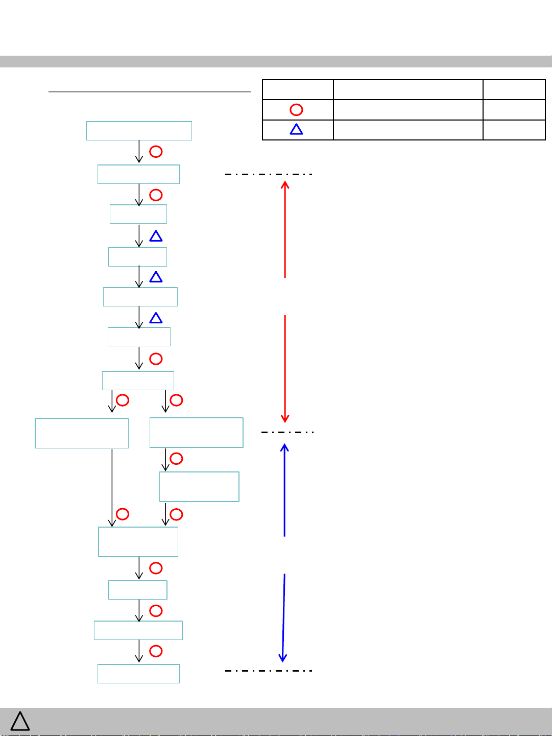
10. Cooling Cycle Heavy Repair
Confirm N2 sealing and packing conditions before use.
10-1. Summary of Heavy Repair
Process Contents Tools
Remove refrigerant
residuals
Parts replacement
and welding
Vacuum Evacuate for more than forty minutes after connecting
Refrigerant charging
and charging inlet
welding
Cut charging pipe ends(compressor & dryer) and
discharge refrigerant from dryer and compressor.
Confirm refrigerant (R134a or R600a) and oil for
compressor and dryer.
Use good one for welding and assembly.
Weld under nitrogen gas atmosphere.
Repair in a clean and dry place.
manifold gauge hose and vacuum pump to high (dryer)
and low (compressor) pressure sides.
Weigh and control the bombe in a vacuum conditions
with electronic scales and charge through compressor
inlet (process tube).
Charge while refrigerator operates.
Weld carefully after inlet pinching.
Nipper, side cutters
Pipe, gas welder, N2 gas
Vacuum pump, manifold gauge
Bombe(mass cylinder),
refrigerant manifold gauge,
electronic scales, punching off
flier, gas welding machine
WARNING
!
Check
refrigerant leak
and cooling
capacity
Compressor
compartment and
tools arrangement
Transportation and
installation
To avoid risk of electrical shock that can cause death or severe personal injury,
disconnect unit from power before servicing unless tests require power.
Check leak at weld joints.
※ Note :Do not use soapy water for check.
Check cooling capacity
→ Check condenser manually to see if warm.
→ Check hot pipe manually to see if warm.
→ Check frost formation on the whole surface of the
evaporator.
Remove flux from the silver weld joints with soft
brusher wet rag. (Flux may be the cause of corrosion
and leaks.(
Clean tools and store them in a clean tool box or in
their place.
Installation should be conducted in accordance with the
standard installation procedure. (Leave space of more
than 5 cm from the wall for compressor compartment
cooling fan mounted model.)
Electronic leak detector, driver.
Copper brush, rag, tool box
48
/ 79

10. Cooling Cycle Heavy Repair
10-2. Precautions During Heavy Repair
Items Precautions
Use of tools Use special parts and tools for R-134a or R-600a
Removal of retained
refrigerant.
Replacement of
dryer
1) Input ‘Forced Comp On Mode’ at Control Panel.
(
※ To force open the step valve for 2 evaporators in series:
Press/hold “Refrigerator Temp” and Freezer Temp” buttons,
then press “Light” button 5 times.)
Turn off a refrigerator after 10 Minutes to open STEP VALVE.
2) Remove retained refrigerant more than 5 minutes after turning off a refrigerator.
(If not, oil will leak inside.)
3) Remove retained refrigerant by cutting first high pressure side (dryer part) with a nipper
and then cut low pressure side. (If the order is not observed, oil leak will happen.)
Be sure to replace dryer when repairing pipes and injecting refrigerant.
WARNING
!
Nitrogen blowing
welding
Others
To avoid risk of electrical shock that can cause death or severe personal injury,
disconnect unit from power before servicing unless tests require power.
Weld under nitrogen atmosphere in order to prevent oxidation inside a pipe.
(Nitrogen pressure : 0.1~0.2 kg/cm2.)
1) Nitrogen only should be used when cleaning inside of cycle pipes inside and sealing.
2) Check leakage with an electronic leakage tester.
3) Be sure to use a pipe cutter when cutting pipes.
4) Be careful not the water let intrude into the inside of the cycle.
49
/ 79

10. Cooling Cycle Heavy Repair
10-3. Practical Work for Heavy Repair
Items Precautions
1. Removal of
residual refrigerant
2. Nitrogen
blowing
welding
1) Remove residual refrigerant more than 5 minutes later after turning off the refrigerator.
(If not, compressor oil may leak inside.)
2) Remove retained refrigerant slowly by cutting first high pressure side (dryer part) with a
nipper and then cut low pressure side.
When replacing a dryer :
Weld ①and② parts by blowing nitrogen (0.1~0.2kg/cm2) to high pressure side after
assembling a dryer.
When replacing a compressor :
Weld ③and④ parts by blowing nitrogen to the low pressure side.
※ Note) For other parts, nitrogen blowing is not necessary because it does not
produce oxidized scales inside pipe because of its short welding time.
■ KEYPOINTING ■
Welding without nitrogen blowing produces oxidized scales inside a pipe,
which affect on performance and reliability of a product.
WARNING
!
To avoid risk of electrical shock that can cause death or severe personal injury,
disconnect unit from power before servicing unless tests require power.
50
/ 79

10. Cooling Cycle Heavy Repair
10-3. Practical Work for Heavy Repair (continued)
Items Precautions
3.Vacuum
degassing
4.Refrigerant
charging
Pipe Connection :
Connect a “red” hose to the high pressure side and a “blue” hose to the low pressure side.
Vacuum Sequence :
Open ①,② valves and evacuate for 40 minutes. Close valve ①.
■ KEYPOINTING ■
1) If power is applied during
vacuum degassing, vacuum
degassing shall be more effective.
2) Operate compressor while
charging refrigerant.
(It is easier and more certain
to do like this.)
Charging sequence :
1) Check the amount of refrigerant supplied to each model after completing vacuum
degassing.
2) Evacuate bombe with a vacuum pump.
3) Measure the amount of refrigerant charged.
→ Measure the weight of an evacuated bombe with an electronic scale.
→ Charge refrigerant into a bombe and measure the weight.
→ Calculate the weight of refrigerant charged into the bombe by subtracting
the weight of an evacuated bombe.
■ KEYPOINTING ■
1) Be sure to charge the refrigerant at around 25°C.
2) Be sure to keep -5g in the winter and +5g in summer.
※ Calculation of amount of refrigerant charged (Wc)
Wc = Wa - Wb
Wa : weight after charging
Wb : weight before charging
( = weight of an evacuated cylinder)
WARNING
!
To avoid risk of electrical shock that can cause death or severe personal injury,
disconnect unit from power before servicing unless tests require power.
51
/ 79

10. Cooling Cycle Heavy Repair
10-3. Practical Work for Heavy Repair (continued)
Items Precautions
4.Refrigerant
charging
(continued)
5. Gas-leakage test
6. Pipe arrangement
in each cycle
4) Refrigerant Charging
Charge refrigerant while operating a compressor as shown above.
5) Pinch a charging pipe with a pinch-off pliers after completion of charging.
6) Lockring the end of a pinched charging pipe with lockring and take a gas leakage test on
the welded parts.
Take a leakage test on the welded or suspicious area with an electronic leakage tester.
Check each pipe is placed in its original place before closing a cover back-M/C after
completion of work.
9-4. Standard Regulations for Heavy Repair
1) Observe the safety precautions for gas handling.
2) Use JIG (or wet towel) in order to prevent electric wires from burning during welding.
(In order to prevent insulation break and accident.)
3) The inner case shall be melted and insulation material (polyurethane) shall be burnt if not cared
during welding inner case parts.
4) The copper pipe shall be oxidized by overheating if not cared during welding.
5) Not allow the aluminum pipes to contact to copper pipes. (In order to prevent corrosion.)
6) Make sure that the inner diameter should not be distorted while cutting a capillary tube.
7) Be sure that a suction pipe and a filling tube should not be substituted each other during welding.
( High efficiency pump.)
WARNING
!
To avoid risk of electrical shock that can cause death or severe personal injury,
disconnect unit from power before servicing unless tests require power.
52
/ 79

11. Disassemble/Assemble Procedures
11-1. Holder Water Filter Assembly
※ Follow the reverse order when assembling.
Step Description Step Description
Remove a screw
Turn off the main water supply to the appliance.
1 5
Separate the tube
fixture on the upper left
side cabinet back face.
2 6
Pull down the Holder Assembly and tubes gently
to remove.
Separate the tube
fixtures, if necessary.
3
Remove ¼” tube connected
to water filter outlet from the
water valve while pressing
4
□ Remark :
• Remove any residual matter inside the water supply line after installation.
1) Turn on the main water supply to the refrigerator .
2) Dispense water using dispenser for approx.10min to clean water and remove air from the lines.
3) And then check there are no water leaks or drips coming out from the water filter and dispenser.
4) If necessary, run water through the dispenser more.
the part (A). Remove the
locking clip before pushing
the part (A).
See the left figure.
MODEL : RFP71KE**
④
①
③
②
① Black(1/4”) – Ice Maker Tube(R room)
② White(1/4”) – Water Filter Outlet
③ White(5/16”) – Water Tank Inlet
④ Blue(1/4”) - Ice Maker tube(F room)
MODEL : RFP71KD**
①
③
②
WARNING
!
To avoid risk of electrical shock that can cause death or severe personal injury,
disconnect unit from power before servicing unless tests require power.
53
/ 79

11. Disassemble/Assemble Procedures
11-2. Water Tank and Cover Vegetable Assembly
※ Follow the reverse order when assembling.
Step Description Step Description
Remove two vegetable cases.
1 5
2 6
Press two fixing hooks in top of the divider and
pull the divide out from the vegetable cover.
3 7
Push the underside of the divider back and lift it
up. And then remove it from the pantry cover.
Turn off the main water supply to the appliance.
Remove one screws
and pull the tank to
the front.
Take off the front cover from
the water tank assembly to
see the water storage
condition.
※ The water need to be
removed from the water line
of refrigerator to replace new
tank.
Unscrew the water valve
assembly in machine room.
And separate the 5/16”(the big
4 8
Remove the vegetable cover.
□ Remark :
• Remove any residual matter inside the water supply line after installation.
1) Turn on the main water supply to the refrigerator .
2) Dispense water using dispenser for approx.10min to clean water and remove air from the lines.
3) And then check there are no water leaks or drips coming out from the water tank and dispenser.
4) If necessary, run water through the dispenser more.
WARNING
!
To avoid risk of electrical shock that can cause death or severe personal injury,
disconnect unit from power before servicing unless tests require power.
one) tube from water valve.
Be careful not to be wet on
the floor. Remove the water
inside water tank and water line.
54
/ 79

11. Disassemble/Assemble Procedures
11-2. Water Tank and Cover Vegetable Assembly (continued)
Step Description
Separate the fixture to protect
5/16”(the big one) tube from
bending damage.
9
※ Follow the reverse order when assembling.
After removing the water
toward the machine room, put a
large cup on dispenser and
prepare to fill the remain water
10
11
Remove the top hinge cover and disconnect
water tube from the water tube fitting.
12
Remain
Water
In Tank
in door water line.
Tilt the tank toward
the under right side
and then pull the tank
and tubes out slowly
to remove.
Water Tank Assembly
(tank + tubes + cover + heater + …)
Water
Tubes
OUT
IN
5/16” Tube from
machine room
¼” Tube from
the top hinge cover
OUT
Water
Tank
IN
□ Remark :
• Cutting 5/16” plastic tube can make disassembly from valve easier. But Be careful not to be wet on the floor.
• The water line must be fully inserted into the water tube fitting to prevent water leakage.
WARNING
!
To avoid risk of electrical shock that can cause death or severe personal injury,
disconnect unit from power before servicing unless tests require power.
55
/ 79

11. Disassemble/Assemble Procedures
11-3. Hose Ice Maker Tube Assembly
※ Follow the reverse order when assembling.
Step Description Step Description
Separate the cover
icemaker Water tube
on the top of cabinet
1 5
2 6
3 7
Using (-) driver.
Pull the water outlet
parts.
Remove a lock clip
from the bend-type
fitting.
Remove the
icemaker water
tube cover.
Remove water tube from the water tube fitting.
Pull out the tube to remove from
the fixtures on back of cabinet.
4 8
Remove one screw attached to the cover
Remove the check valve.
□ Remark :
WARNING
!
To avoid risk of electrical shock that can cause death or severe personal injury,
disconnect unit from power before servicing unless tests require power.
Pull out the tube in
the direction of the
top cabinet to remove.
56
/ 79

11. Disassemble/Assemble Procedures
11-4. Icemaker
Step Description
Hold the handle of the bucket
and then pull it straight out.
1
Unscrew and remove the
wires cover.
2
※ Follow the reverse order when assembling.
Disconnect the connector
of icemaker.
3
Remove the icemaker.
4
□ Remark :
• If the bucket does not fit, turn the helix 90 degree and try again.
WARNING
!
To avoid risk of electrical shock that can cause death or severe personal injury,
disconnect unit from power before servicing unless tests require power.
57
/ 79

11. Disassemble/Assemble Procedures
11-5. Fixture Geared Motor
※ Follow the reverse order when assembling.
Step Description
1
Separate wires
from hooks gently.
2
3
GOOD
Disconnect the
connector of the
Fixture Geared
Motor assembly.
Pull a hook
to the right
to remove.
Remove the Fixture
G/Motor.
4
□ Remark :
• Locking Good : Put and arrange the connectors deeply into the right side of the motor.
WARNING
!
To avoid risk of electrical shock that can cause death or severe personal injury,
disconnect unit from power before servicing unless tests require power.
58
/ 79

11. Disassemble/Assemble Procedures
11-6. Pantry Drawer Cover and Cover Multi-duct Assembly
※ Follow the reverse order when assembling.
Step Description Step Description
Remove vegetable cases,
vegetable cover, pantry
drawer. Loosen two screws
1 5
2 6
Lift up the cover and pull it out a little to remove the
connector from back wall.
3
Remove two caps with a thin flat tool.
from water tank assembly.
Hold the top side of
the Cover Multi-duct
and then pull it to
release hooks.
Disconnect two sensor
connectors and two
damper Connectors
from back wall.
Loosen the upper
screw(big one;
outside diameter of
4
□ Remark :
• Do not use the small screw in the upper side of Multi-duct Assembly. The screw could be loose.
WARNING
!
To avoid risk of electrical shock that can cause death or severe personal injury,
disconnect unit from power before servicing unless tests require power.
thread 5mm) and
lower screw(small
one; outside diameter
of thread 4mm)
59
/ 79

11. Disassemble/Assemble Procedures
11-7. Refrigerator Sensor, Pantry Drawer Sensor, Dampers in Cover Multi-duct Assembly
※ Follow the reverse order when assembling.
Step Description
1
Separate the insulator from the multi-duct cover.
2
Remove R sensor on the upper side of
cover. Remove the pantry drawer sensor
on the lower side of cover.
3
□ Remark :
Take off the tape and
separate insulator covered
pantry drawer damper. And
remove the damper.
Before disassembly check
the arrangement of wires
and connector.
M-PCB
WARNING
!
To avoid risk of electrical shock that can cause death or severe personal injury,
disconnect unit from power before servicing unless tests require power.
60
/ 79

11. Disassemble/Assemble Procedures
11-8. Control Panel PCB and Wires in Pantry Drawer Cover Assembly
※ Follow the reverse order when assembling.
Step Description Step Description
Remove two screws to
disassemble the pantry
control panel PCB and
1 5
wires.
Separate the wires from hooks in the pantry cover.
2
3
Separate the PCB and disconnect the connector.
4
Unlock and pull the wire cover to remove the wires
assembly.
Remove the cover in front of
the pantry drawer cover
assembly. And loosen two
screws to remove the PCB.
□ Remark :
WARNING
!
To avoid risk of electrical shock that can cause death or severe personal injury,
disconnect unit from power before servicing unless tests require power.
61
/ 79

11. Disassemble/Assemble Procedures
11-9. Freezer Louver Assembly
※ Follow the reverse order when assembling.
Step Description Step Description
1 5
Disconnect the connectors of F fan motor and F
Remove freezer drawers.
2
Press the left fixing hook of the rail system.
Holding the top of the F door, pull it out a little to
release. Repeat release the right hook as same way.
And then fully open the door to remove.
sensor.
Fixture F Rail *M
(Material : steel bar)
Gear F rail *M
(Material : plastic)
Supporter F Rail
Gear *M
(Material : plastic)
3
Remove two screws.
4
Holding the left side of Louver, pull it forward.
Be careful no to damage the wires in the right side.
□ Remark :
• After installing the f door, fully push and close it to align left and right rack gear tooth. And check locking rail system.
• If necessary, assemble one Gear F Rail *M in the rail system. Push and assemble another one Gear Rail F *M on
opposite side of rail.
Rail System
WARNING
!
To avoid risk of electrical shock that can cause death or severe personal injury,
disconnect unit from power before servicing unless tests require power.
62
/ 79

11. Disassemble/Assemble Procedures
11-10. Freezer Sensor, F Fan and Fan Motor
※ Follow the reverse order when assembling.
Step Description Step Description
1 5
Remove the tape to separate wires of F-sensor and
F Fan motor.
2 6
Loosen 4 screws
marked by rectangle.
And remove F Fan
motor assembly from
the Louver.
Remember how to
arrange the wires.
Remove wires from 3
hooks and loosen 2
screws to remove the
motor.
Loosen 7 screws marked by circle and rectangle to
remove F-sensor.
Separate the wires from
hook.
3 7
Make a gap slightly
and remove the Dsensor from the
hook.
4 8
□ Remark :
NG GOOD
Supporting the back side of fan
with a finger, pull out and
remove the fixing spring with a
long nose plier. If necessary,
scratch the lock paint(green
one).
※ The diameter and shape of
this F Fan is different from the
R and C Fan.
Break the shaft(plastic) of fan blade. Do not use the
old fan again. Be careful not to damage the shaft of
motor if the motor is used again. Remove the fan
and motor.
NG
Show the left picture. If you strongly
pull out the fan blade and remove, the
fan and shaft of the motor will be
damage and have a bad performance.
WARNING
!
To avoid risk of electrical shock that can cause death or severe personal injury,
disconnect unit from power before servicing unless tests require power.
63
/ 79

11. Disassemble/Assemble Procedures
11-11. Refrigerator Fan and Fan Motor in freezer
※ Follow the reverse order when assembling.
Step Description Step Description
Supporting the back side of fan
with a finger, pull out and
remove the fixing spring with a
long nose plier. If necessary,
1 5
Loosen 3 special
screws(stay bolts) and
disconnect the
connector.
Separate the R Fan
Motor assembly.
2 6
Break the shaft(plastic) of fan blade. Do not use the
old fan again. Be careful not to damage the shaft of
motor if the motor is used again.
Remove the fan and motor.
scratch the lock paint(green
one).
※ The diameter and shape of
this R Fan is different from the
F and C Fan.
Remember how to
arrange the wires.
Remove wires from a
3 7
4
□ Remark :
hooks. And loosen a
screw to remove the
cable clamp.
Loosen the opposite
screw and remove
the rubber vibration
isolator.
NG
If necessary, remove the
rubber vibration isolator in the
front of the Fixture R Motor.
Show the left picture. If you
strongly pull out the fan blade
and remove, the fan and shaft
of the motor will be damage
and have a bad performance.
WARNING
!
To avoid risk of electrical shock that can cause death or severe personal injury,
disconnect unit from power before servicing unless tests require power.
64
/ 79

11. Disassemble/Assemble Procedures
11-12. Freezer Defrost Sensor and Heater in the Evaporator Assembly
※ Follow the reverse order when assembling.
Step Description Step Description
Remove the
connectors
1 5
2 6
Pull out the evaporator from 3 hooks on the
back wall.
3 7
※ Two D-Sensor
with each
connector
※ One D-Heater
with two
Connectors
Cut the cable
ties and
remove the
defrost
sensors on left
and right side
of Eva.
Remove two temp
fuses of defrost heater.
Spread out the upper
clamping parts (the left and
right side of Eva) to remove
the pipe of defrost heater.
Bend out the lower clamping
parts (the left and right side
of Eva) to remove the pipe of
defrost heater.
Cut the cable ties
and remove two
temp fuse covers on
4 8
□ Remark :
• Do not miss 4 cable ties(2 big, 2 small). They could block two
drain holes and the drain water will overflow into freezer.
WARNING
!
To avoid risk of electrical shock that can cause death or severe personal injury,
disconnect unit from power before servicing unless tests require power.
left and right side of
Eva.
Remove the heater from Eva.
65
/ 79

11. Disassemble/Assemble Procedures
11-13. Defrost Sensor in the Ice Maker Evaporator Assembly
Step Description
Remove eight screw attached
to the cover.
And remove cover.
1
2
※ Follow the reverse order when assembling.
Straighten the 4 bent positions of the cover plate.
3
4
□ Remark :
□ Remark :
Remove the cover plate.
Cut the cable tie and remove the defrost
sensor on right side of Eva.
WARNING
!
To avoid risk of electrical shock that can cause death or severe personal injury,
disconnect unit from power before servicing unless tests require power.
66
/ 79

11. Disassemble/Assemble Procedures
11-14. Defrost Heater in the Ice Maker Evaporator Assembly
※ Follow the reverse order when assembling.
Step Description Step Description
Remove eight screw attached
to the cover.
And remove cover.
1 5
2 6
Welding removes the
remaining pipes.
※ Caution Be careful
not to melt the parts.
Cutting the pipe using a tool.
Remove the two
connectors.
3 7
Hold the top of the
eva and then pull.
4 8
□ Remark :
□ Remark :
Insert Eva all the way into the pipe.
Assemble by
pressing in the
direction of the
arrow so that the
EVA is assembled
at the bottom..
Fixing the pipe by
welding.
※ Caution Be careful
not to melt the parts.
WARNING
!
To avoid risk of electrical shock that can cause death or severe personal injury,
disconnect unit from power before servicing unless tests require power.
67
/ 79

11. Disassemble/Assemble Procedures
11-15. Condenser Fan Motor in the Machine Room
※ Follow the reverse order when assembling.
Step Description Step Description
Disconnect the connector
of C Fan Motor.
1 5
Break the shaft(plastic) of fan blade. Do not use the
old fan again. Be careful not to damage the shaft of
motor if the motor is used again. If necessary,
scratch the lock paint(green one).
Loosen 2 screws.
2 6
Push the fixing hook
in the left direction
to separate the C
3 7
Supporting the back side of
fan with 2 fingers, pull out and
remove the fixing spring with
a long nose plier. If necessary,
4
scratch the lock paint(green
one).
※ The diameter and shape of
this C Fan is different from the
F and C Fan.
Fan Motor
Assembly.
Loosen 2 screws.
Remember how to
arrange the wires.
Remove the C fan motor.
□ Remark :
WARNING
!
To avoid risk of electrical shock that can cause death or severe personal injury,
disconnect unit from power before servicing unless tests require power.
68
/ 79

11. Disassemble/Assemble Procedures
11-16. Freezer and Refrigerator Door Switches
※ Follow the reverse order when assembling.
Step Description Step Description
Remove the F door
switch with flat-blade
screwdriver.
1 1
Loosen 5 screws and remove the top hinge cover.
Disconnect the
connector.
2
□ Remark :
2
Remove two door switches and disconnect the
connectors.
WARNING
!
To avoid risk of electrical shock that can cause death or severe personal injury,
disconnect unit from power before servicing unless tests require power.
69
/ 79

11. Disassemble/Assemble Procedures
11-17. Front Control Panel Dispenser in the Left Refrigerator Door
Step Description
Loosen a screw at
the bottom side of
Front Control Panel.
1
Grip the bottom side
of the FCP with two
hands and lift and
2
pull it forward to
remove.
※ Follow the reverse order when assembling.
3
□ Remark :
Disconnector the
connector.
WARNING
!
To avoid risk of electrical shock that can cause death or severe personal injury,
disconnect unit from power before servicing unless tests require power.
70
/ 79

11. Disassemble/Assemble Procedures
11-18. Dispenser Lever
※ Follow the reverse order when assembling.
Step Description Step Description
Remove the Front
Control Panel.
Loosen 4 screws to
1 5
2 6
remove the Box
Dispenser Ice
Shutter Assembly.
Remember how to link the dispenser flap moving
motor and the Box Dispenser Ice shut Assembly.
Loosen a screw to remove the motor.
Pull and remove the
assembly.
Release the hook and remove the
water dispenser lever switch.
Remember how to arrange the
dispenser water tube.
See the yellow tape for guide line.
3 7
4
□ Remark :
Separate the water tube which is
assembled to hook and cylinder.
Disconnect 5
connectors.
Loosen 2 screws and the
lever kit with the switch.
WARNING
!
To avoid risk of electrical shock that can cause death or severe personal injury,
disconnect unit from power before servicing unless tests require power.
71
/ 79

11. Disassemble/Assemble Procedures
11-19. Mullion Bar Assembly
Step Description
1
Loosen 2 screws.
Grip the upper and lower side of the bar.
Push it up to remove.
※ Follow the reverse order when assembling.
※ Assemble Procedures
at Middle Hinge Part
Align the 2 screw holes on
the door with the mounting
holes on the middle hinge of
mullion bar after fitting two
hooks certainly.
And then tighten 2 screws.
2
□ Remark :
WARNING
!
Disconnect the mullion bar
heater(AC) connector.
To avoid risk of electrical shock that can cause death or severe personal injury,
disconnect unit from power before servicing unless tests require power.
72
/ 79

11. Disassemble/Assemble Procedures
11-21. Interior F/R Lamp
※ Follow the reverse order when assembling.
Step Description Step Description
Pushing the front side
of F lamp cover, pull it
down to remove.
1 2
Loosen 2 screws
Loosen 2 screws to
remove the lamp.
2 3
Maker a gap between the lamp holder and the top
side of refrigerator using thin flat tip tool.
And pull the holder down to remove.
Disconnect the F lamp
connector.
3 4
1 5
Release two hooks at the back side of R lamp
cover carefully and remove the ramp cover.
□ Remark :
Disconnect the R lamp connector.
Release hooks and remove the lamp.
WARNING
!
To avoid risk of electrical shock that can cause death or severe personal injury,
disconnect unit from power before servicing unless tests require power.
73
/ 79
 Loading...