

Kenmore 110.42836200, 110.42824200, 110.42922200, 110.42832200, 110.42932200 User Manual
...Page 1
Manual No:
261 10701
Developmental
Resources
ELITE
MODEL
NUMBERS:
1 1
0.42822200
1 1
0.42832200
1 1
0.42824200
1 1
0.42826200
1 10.42834200 1 1
0.42836200
1 1
0.42922200
1 1
0.42932200
11
0.42924200
1 1
0.4293
4200
110.42926200 1 1
0.42936200
HE{"
Developmental Resources
@
2001
Sears, Roebuck and
Co.
HEt'"
Front-Load
i ng Automat i c
Washer
FIELD
COURSE
9373
Page 2
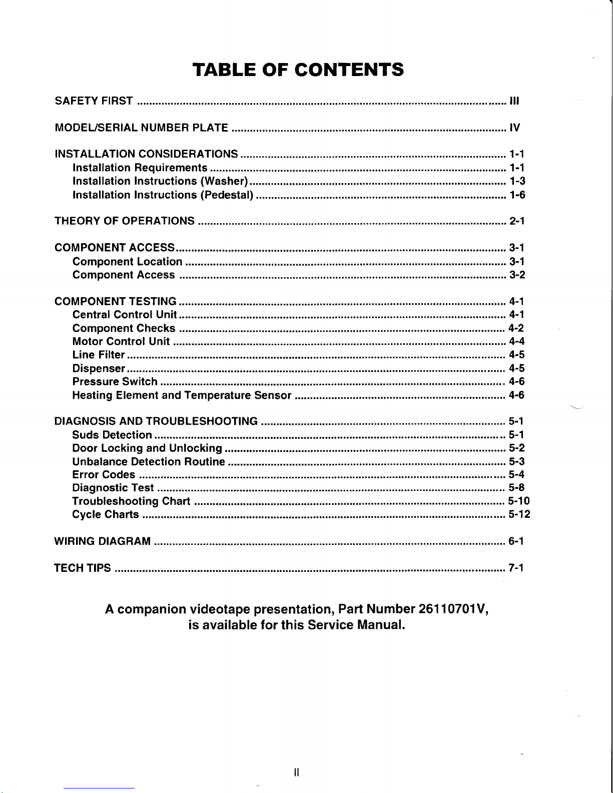
TABLE
OF CONTENTS
SAFETY FTRST .............. ill
MODEUSERIAL NUMBER PLATE
..............
....... IV
TNSTALLATTON CONSTDERATTONS
..................
1-1
Installation Requirements........... ................. 1-1
Installation Instructions
(Washer)................
.................
1-3
Installation Instructions
(Pedestal)..............
................
1-6
THEORY
OF OPERATTONS
..............2-1
coMPoNENT ACCESS............... .......3-1
Component Location
..................3-1
Component Access
...3-2
coMPoNENT TEST|NG..............
....... 4-1
Central Gontrol
Unit.......... ........... 4-1
Component Checks
................... 4-2
Motor Control Unit ..........
..............4-4
Line Filter
...................4-s
Dispenser
.................. 4-5
Pressure
Switch
.......... 4-6
Heating Element and Temperature Sensor
.................. 4-6
DIAGNOSIS
AND TROUBLESHOOTING
........... 5-1
Suds Detection
.........5-1
Door Locking and Unlocking
.......5-2
Unbalance
Detection Routine
......5-3
Error Codes
..............5-4
Diagnostic Test .........
.................
5-B
Troubleshooting Chart
.............
5-10
Cycle Charts
.............5-12
wtRtNG
DTAGRAM
............6-1
TECH T|PS ........
................7-1
A companion videotape
presentation,
Part Number
261 10701V,
is available for
this Service
Manual.
Page 3

Your
safety
and the safety of others are
very important.
We have
provided
many important
safety messages in this manual and on the appliance. Always read
and obey all safety messages.
This
is the
safety alert symbol.
This
symbol alerts
you
to
potential
hazards that can kill or hurt
you
and
others.
All
safety messages will follow
the safety alert symbol and either the
word
'DANGER"
or
"WARNlNG."
These words mean:
You can be
killed
or seriously injured if
you
don't
immediately follow instructions.
You can be
killed
or seriously injured if
you
don't
follow instructions.
All
safety messages willtellyou
what the
potential
hazard is, tellyou how to
reduce
the chance of injury,
and tell
you
what
you
can happen if
the
instructions
are
not followed.
)g
ELECTRICAL
SHOCK HAZARD
Disconnect
power
before
servicing.
Replace
all
panels
before
operating.
Failure
to do so can result
in death or
electrical shock.
)g
ELECTRICAL SHOCK HAZARD
Plug into a
grounded
3
prong
outlet.
Do
not remove
ground prong.
Do not use adapter.
Do not use an extension cord.
Failure to follow these instructions can
result in death, fire, or electrical shock.
ill
Page 4
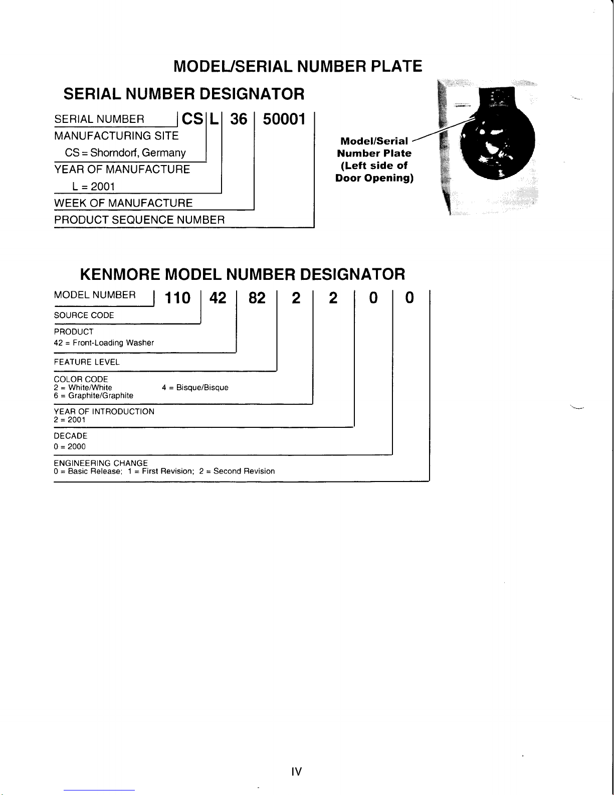
MODEUSERIAL NUMBER
PLATE
SERIAL
NUMBER DESIGNATOR
SER|AL NUMBER
I
cslL
MANUFACTURING-ITE
I
CS = Shorndorf, Germany
I
ffi
L = 2001
Model/Serial
Number
Plate
(Left
side
of
Door Opening)
WEEK OF MANUFACTURE
PRODUCT
SEQUENCE
NUMBER
KENMORE MODEL NUMBER
DESIGNATOR
MopELNUMBER
|
110 | 42
|
g2
PRODUCT
42 = Front-Loading
Washer
COLOR CODE
2 = WhileMhite
6 = Graphile/Graphite
YEAR
OF
INTRODUCTION
2 = 2001
DECADE
0
=
2000
ENGINEERING
CHANGE
0
=
Basic Release; 1 = First Revision; 2
=
Second
Revision
IV
Page 5
Section One
Parts supplied:
n_
1-F
\-_-r
Beaded
strap
it
f.1
lf You
Have
Laundry tub or
standpipe taller
than 96
in.
(2.4
m)
Overhead sewer
Floor drain
Drain hose too shoil
Waterfaucets
beyond
reach of fill hoses
lf
You Have You Will Need
to
Buy
Sump
pump
system
(if
not
al-
ready available)
Standard 20
gal. (76
L),30 in.
(76.2
cm) tall drain tub or
util-
ity
sink and sump
pump
(avail-
able f rom local
plumbing
sup-
pliers)
Siphon break, Part Number
285834;
add
itional
d rain hose
Part Number
8318155; and
connector
kit,
Part Number
285835
Drain hose extension kit, Part
Number
285863
2 longer water fill hoses:
6 ft.
(1.8
m) Part Number
76314,10ft.
(3.0
m)Part
Num-
ber 350008
I NSTALLATI
ON CONSI
DERATIONS
INSTALLATION
REQUIREMENTS
Tools
and
Parts
Assemble
the necessary
tools and supplies before
be-
ginning
the
washer
installation. The
parts
supplied
are
in
the
washer
drum.
Tools
needed
for connecting the water inlet
hoses
.
Pliers
(that
open to 1 9/16
in.
[39.5
mm])
.
Flashlight(optional)
Tools needed for installation
.
Open
end
wrench 5/8 in.
(17
mm)
and% in.
(13
mm)
.
Level
.
Wood
block
(2"
x 4")
.
Ruler
or
measuring
tape
Transport
bolt hole
plug
(4)
Alternate Parts You May Need
Parts listed
are available
from
your
local
Sears
slore
or Sears Service Center.
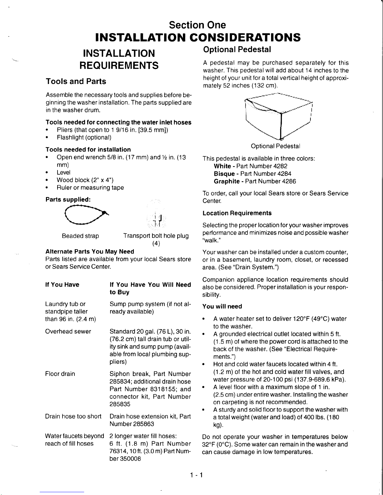
Optional
Pedestal
A
pedestal
may
be
purchased
separately for
this
washer.
This
pedestalwilladd
about 14 inches
to the
height of
your
unit for a total vertical height
of approxi-
mately 52
inches
(132
cm).
Optional
Pedestal
This
pedestal
is
available
in
three colors:
White
-
Part Number 4282
Bisque
-
Part Number 4284
Graphite
-
Part Number 4286
To order, call
your
local Sears store
or Sears Service
Center.
Location Requirements
Selecting the
proper
location for
your
washer improves
performance
and
minimizes noise
and
possible
washer
"walk."
Your washer can be installed under a custom counter,
or
in
a basement,
laundry
room, closet, or recessed
area.
(See
"Drain
System.")
Companion
appliance
location
requirements
should
also be considered.
Proper
installation is
your
respon-
sibility.
You willneed
.
A
water heater set to deliver 120'F
(49'C)water
to lhe
washer.
.
A
grounded
electricaloutlet
located
within 5 ft.
(1
.5 m)
of
where the
power
cord is
attached
to
the
back of the
washer.
(See
"Electrical
Require-
ments.")
.
Hot and cold
water faucets located within 4 ft.
(1.2
m)
of the
hot and cold water fill valves,
and
water
pressure
of 20-100
psi
(137.9-689.6
kPa).
.
A levelfloor with a maximum slope of 1 in.
(2.5
cm)
under entire washer. Installing the washer
on carpeting
is not recommended.
.
A sturdy and solid
f loor
to support the
washer with
a
total weight
(water
and
load)
of
400 lbs.
(180
kg).
Do
not operate
your
washer in
temperatures below
32'F
(0"C).
Some
watercan remain in
the
washerand
can cause
damage
in low temperatures.
1-1
Page 6
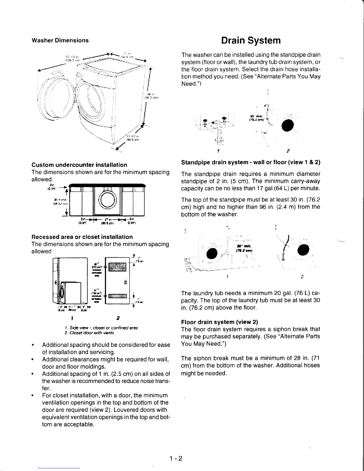
Washer Dimensions
Custom undercounter
installation
The dimensions shown are for the minimum spacing
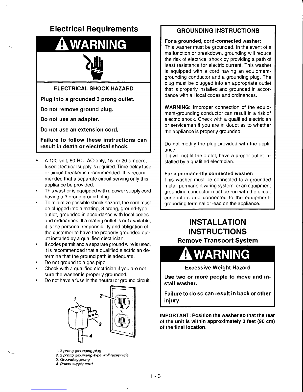
Drain System
The
washer can be
installed
using the standpipe drain
system
(floor
or
wall), the laundry tub drain system, or
the
floor
drain
system. Select the drain
hose installa-
tion
method
you
need.
(See
"Alternate
Parts You May
Need.")
:
Standpipe
drain system
-
wall
or
f loor
(view
1 & 2)
The standpipe
drain
requires a minimum
diameter
standpipe
ol
2 in.
(5
cm).
The minimum
carry-away
capacity
can be
no less than
17
gal
(64
L)
per
minute.
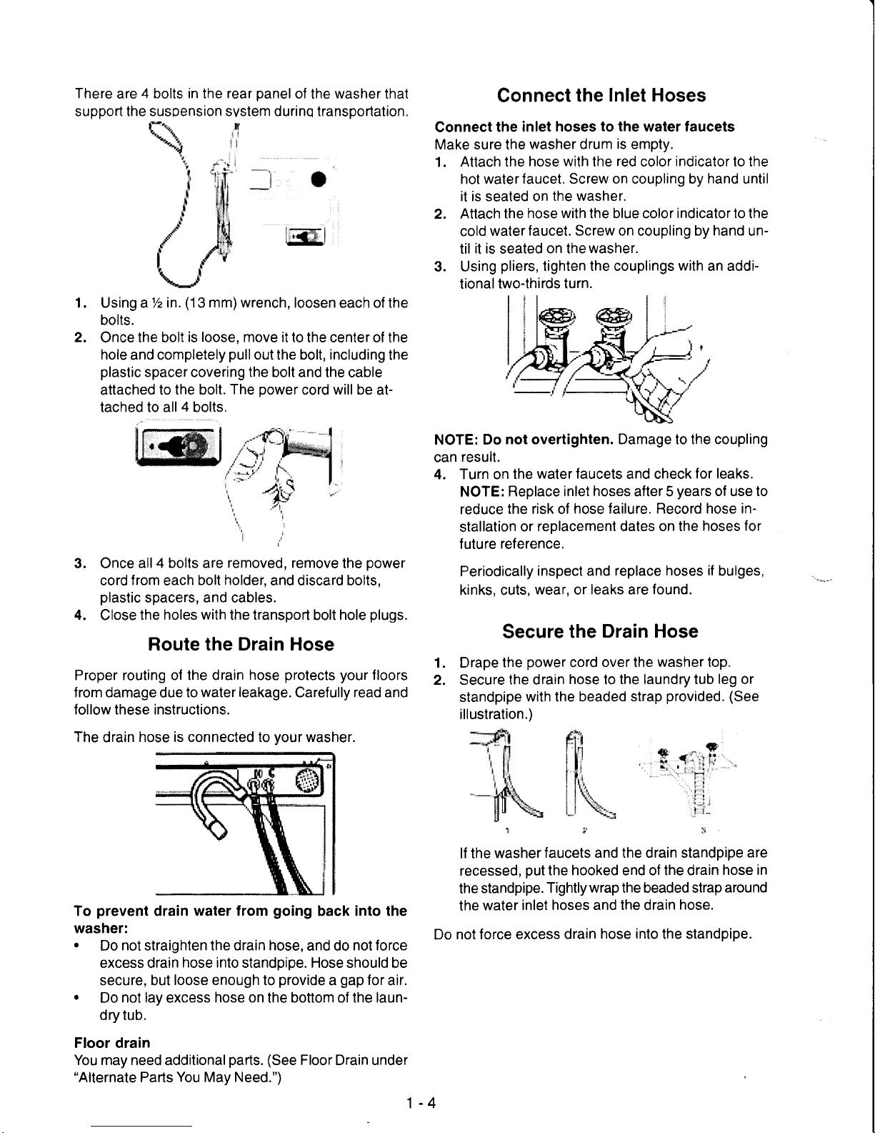
The top
of the standpipe
must
be
at least 30
in.
(76.2
cm)
high and
no higher than 96 in.
(2.4
m) f rom the
bottom
of
the
washer.
I
llli ii
",','r
,,
,li{',,
11.
',',
,
. r' ir.
'.,
i
-'i
tt+,,i.,,.
,)i-
|:
:;*::,
i;sl
/-,
-
allowed.
ltrl
.r-'*-)
I
I
}] { rr{r
i!{
lil vr{
I
Y
81.-*t*-
itn---''f***h
,t'c}!
'
tltlnrr
r
$E!t
Recessed area or
closet installation
The dimensions shown are
for
the
minimum
spacing
allowed
,?tf
Fr!
#
il
l2
r. S'x1r +gu."
c@sr n" rsrfr,$'t ff6f
I; #.qare{ dftn
w*t r*4r$
Additional spacing should be considered
for
ease
of installation and servicing.
Additional clearances
might
be
required for wall,
door and
floor moldings.
Additionalspacing of
1 in.
(2.5
cm) on allsides of
the
washer is recommended to reduce noise transfer.
For
closet
installation, with
a door, the
minimum
ventilation openings in the top
and bottom of
the
door are required
(view
2). Louvered
doors
with
equivalent
ventilation openings in the
top
and bot-
tom are acceptable.
'd:4-";-^.-....-'
The
laundry tub
needs a minimum 20
gal. (76
L) ca-
pacity.
The top of the
laundry
tub
must be at
least
30
in.
(76.2
cm) above the
floor.
Floor drain
system
(view
2)
The
floor drain system
requires a siphon break
that
may be
purchased
separately.
(See
"Alternate
Parts
You
May
Need.")
The siphon
break
must be a minimum
of 28 in.
(71
cm)
from the bottom
of the
washer. Additional hoses
might be
needed.
.l-
t
f'Blr,
pltD/nl
1
''1
lt
t*
llt"p'l
ffi
irF i!i' H r'
l*
'&nd
t*{i
**
1-2
Page 7
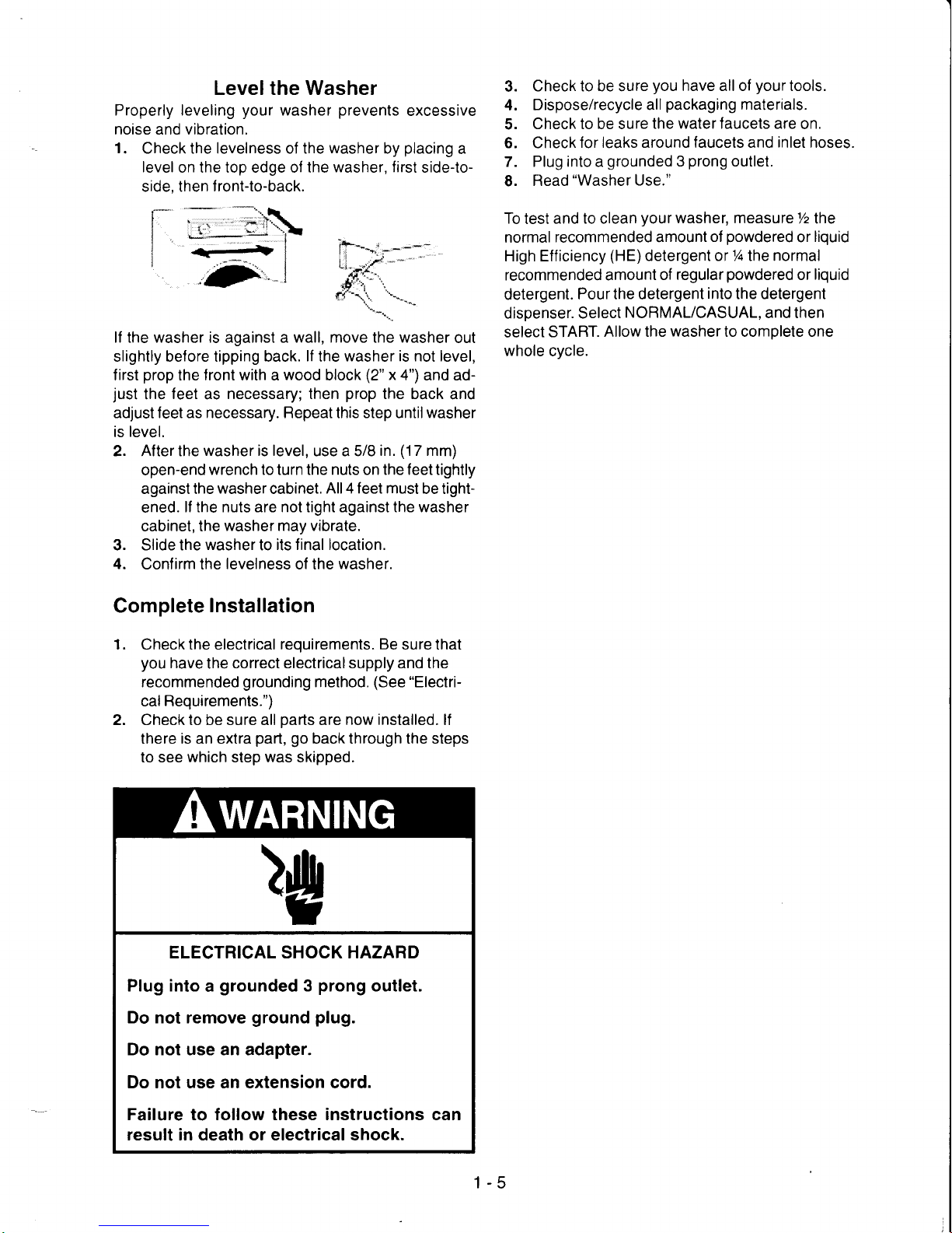
Electrical Requirements
)g
ELECTRICAL
SHOCK HAZARD
Plug into a
grounded 3 prong
outlet.
Do not remove
ground
plug.
Do not use an adaoter.
Do not
use an extension cord.
Failure
to
follow
these
instructions
can
result in death or electrical
shock.
a
a
A 12O-volt, 60-H2.,
AC-only, 15-
or 2O-ampere,
f
used electrical
supply is required. Time-delay f
use
or circuit
breaker is recommended. lt is recommended that a separate circuit serving only this
appliance be
provided.
This washer is
equipped
with
a
power
supply cord
having a 3
prong
ground
plug.
To minimize
possible
shock hazard, the cord must
be
plugged
into a mating, 3
prong,
ground-type
outlet,
grounded
in accordance with local
codes
and ordinances.
lf a mating
outlet
is not
available,
it is the
personal
responsibility
and obligation of
the
customer to have the
properly
grounded
out-
let installed by a
qualified
electrician.
lf codes
permit
and a separate
ground
wrre is
used,
it is
recommended
that a
qualified
electrician de-
termine that the
ground path
is
adequate.
Do not
ground
to a
gas
pipe.
Check with a
qualilied
electrician
if
you
are not
sure the washer
is
properly grounded.
Do not have a
fuse
in the neutral or oround circuit.
f .
:l
Frnq0 Sq"&rrr$lng
pAlF
l
S
prong
trftInotnp"
typa
trxt
natrq@ctu
,3.
Gn"trn*rp
g*nrgr
4.
fiil*er
safig{r c*rs
GROUNDING
INSTRUCTIONS
For a
grounded,
cord-connected
washer:
This washer
must
be
grounded.
In
the event
of
a
malfunction or breakdown,
grounding
will reduce
the
risk
of electrical
shock by
providing a path
of
least resistance
for electric current. This washer
is
equipped
with a cord having
an equipment-
grounding
conductor and a
grounding
plug.
The
plug
must be
plugged
into
an appropriate outlet
that
is
properly
installed
and
grounded
in accor-
dance
with
all
local codes and
ordinances.
WARNING:
lmproper
conneclion of the equip-
ment-grounding
conductor can
result in a risk
of
electric
shock. Check
with
a
qualified
electrician
or serviceman
if
you
are
in
doubt
as
to whether
the
appliance
is
properly grounded.
Do
not modify the
plug provided
with the appli-
ance
-
if it will
not fit
the
outlet,
have
a
proper
outlet
in-
stalled by a
qualified
electrician.
For a
permanently
connected washer:
This washer must be connected to a
grounded
metal,
permanenl
wiring system,
or an equipment
grounding
conductor
must
be
run
with the circuit
conductors
and connected to
the equipment-
grounding
lerminalor
lead
on the appliance.
INSTALLATION
INSTRUCTIONS
Remove
Transport
System
IMPORTANT:
Position
the washer
so
that the rear
of
the unit
is within approximately 3 feet
(90
cm)
of the
final location.
Excessive
Weight Hazard
Use
two or
more
people
to move and in-
stall
washer.
Failure to do
so can
result
in back or other
injury.
1-3
Page 8
There
are
4 bolts in
the
rear
panel
of the washer thal
support the suspension svstem durinq transportation.
Using a lzin.
(13
mm) wrench,
loosen each of the
bolts.
Once the bolt
is loose, move it
to the center of the
hole
and completely
pull
out
the bolt,
including
the
plastic
spacer covering the bolt and
the cable
attached
to the bolt. The
power
cord will be
at-
tached to all 4 bolts.
Connect
the
Inlet Hoses
Connect
the
inlet hoses
to the
water faucets
Make sure the
washer drum
is
empty.
1. Attach
the hose
with
the
red
color
indicator
to the
hot
water faucet. Screw on coupling by
hand
until
it is seated on
the washer.
Attach
the hose
with
the blue color
indicator
to the
cold
water faucet. Screw
on
coupling by
hand
un-
til
it is
seated
on the
washer.
Using
pliers,
tighten the couplings
with
an addi-
tional two-thirds
turn.
NOTE: Do
not overtighten. Damage to the coupling
can
result.
4. Turn on
the
water faucets
and check
for leaks.
NOTE:
Replace
inlet hoses
after 5
years
of use lo
reduce
the risk of
hose failure. Record hose in-
stallation
or
replacement dates on the
hoses for
future
reference.
Periodically
inspect and replace hoses
if
bulges,
kinks, cuts,
wear,
or
leaks are found.
Secure
the
Drain Hose
1. Drape
the
power
cord
over the washer top.
2. Secure
the drain
hose
to
the laundry tub
leg
or
standpipe
with the beaded
strap
provided. (See
illustration.)
1;r.1
lf the
washer
faucets and the drain standpipe
are
recessed,
put
the hooked end of the drain
hose in
the
standpipe.
Tightly wrap the beaded strap
around
the water
inlet hoses and the drain
hose.
Do
not force excess
drain hose
into
the standpipe.
I
2.
3.
1.
2.
lFffie l,"FM
-,r.-.,u
{:
"\
4s
t
t.j
I
3. Once
all4 bolts are removed, remove
the
power
cord
from
each bolt
holder,
and discard bolts,
plastic
spacers, and cables.
4.
Close
the holes with the transport
bolt
hole
plugs.
Route the Drain Hose
Proper routing of the drain
hose
protects
your
floors
f rom damage
due
to water
leakage.
Carefully read and
follow these instructions.
The
drain
hose is connected to
your
washer.
To
prevent
drain
water from
going
back into the
washer:
.
Do
not
straighten
the drain hose,
and do
not force
excess drain
hose into
standpipe. Hose should be
secure, but
loose enough
to
provide a gap
for
air.
.
Do not
lay
excess
hose on
the bottom of the
laun-
dry tub.
Floor drain
You may need additional
parts. (See
Floor Drain under
"Alternate
Parts
You
May
Need.")
$.
{i,l$'.'.
'
t'
'!:1,,
.il
x:
1-4
Page 9
Level the Washer
Properly leveling
your
washer
prevents
excessive
noise and vibration.
1.
Check the levelness of the
washer
by
placing
a
level
on the top edge of lhe
washer, first
side-to-
side, then
f ront-to-back.
lf the washer is against a wall, move the washer
out
slightly before tipping back.
lf
the
washer is not level,
first
prop
the front with a
wood
block
(2"
x
a") and ad-
just
the
leet
as
necessary; then
prop
the back
and
adjust feet as necessary. Repeat this step until washer
is
level.
2. After the
washer is level,
use a 5/8
in.
(17
mm)
open-end
wrench to turn the nuts on the feet tightly
against the
washer
cabinet.
All 4 feet must
be tight-
ened.
lf the nuts are not tight against the washer
cabinet, the
washer may vibrate.
3. Slide the
washer
to
its final location.
4.
Confirm the
levelness
of the
washer.
Complete
Installation
1. Check the electrical
requirements. Be
sure that
you
have
lhe
correct electrical supply and the
recommended
grounding
method.
(See
"Electri-
cal Requirements.")
2. Check to be sure all
parts
are
now installed.
lf
there is an extra
part,
go
back through the steps
to see
which
step
was
skipped.
3.
Check to be sure
you
have all of
your
tools.
4. Dispose/recycle
all
packaging
materials.
5.
Check to be sure
the water faucets are
on.
6. Check
for leaks around faucets and
inlet
hoses.
7. Plug into a
grounded
3
prong
outlet.
L
Read
"Washer
Use."
To
test
and to clean
your
washer, measure
7z the
normal
recommended amount
of
powdered
or
liquid
High Efficiency
(HE)detergent
or%lhe normal
recommended amount
of regular
powdered
or
liquid
detergent.
Pour the detergent
into
the detergent
dispenser. Select
NORMAL/CASUAL,
and then
select
START.
Allow the
washer
to complete one
whole cycle.
i-
)g
ELECTRICAL SHOCK HAZARD
Plug into
a
grounded
3
prong
outlet.
Do not remove
ground
plug.
Do not use an adapter.
Do not use an extension cord.
Failure to follow these instructions can
result in death or electrical shock.
1-5
Page 10
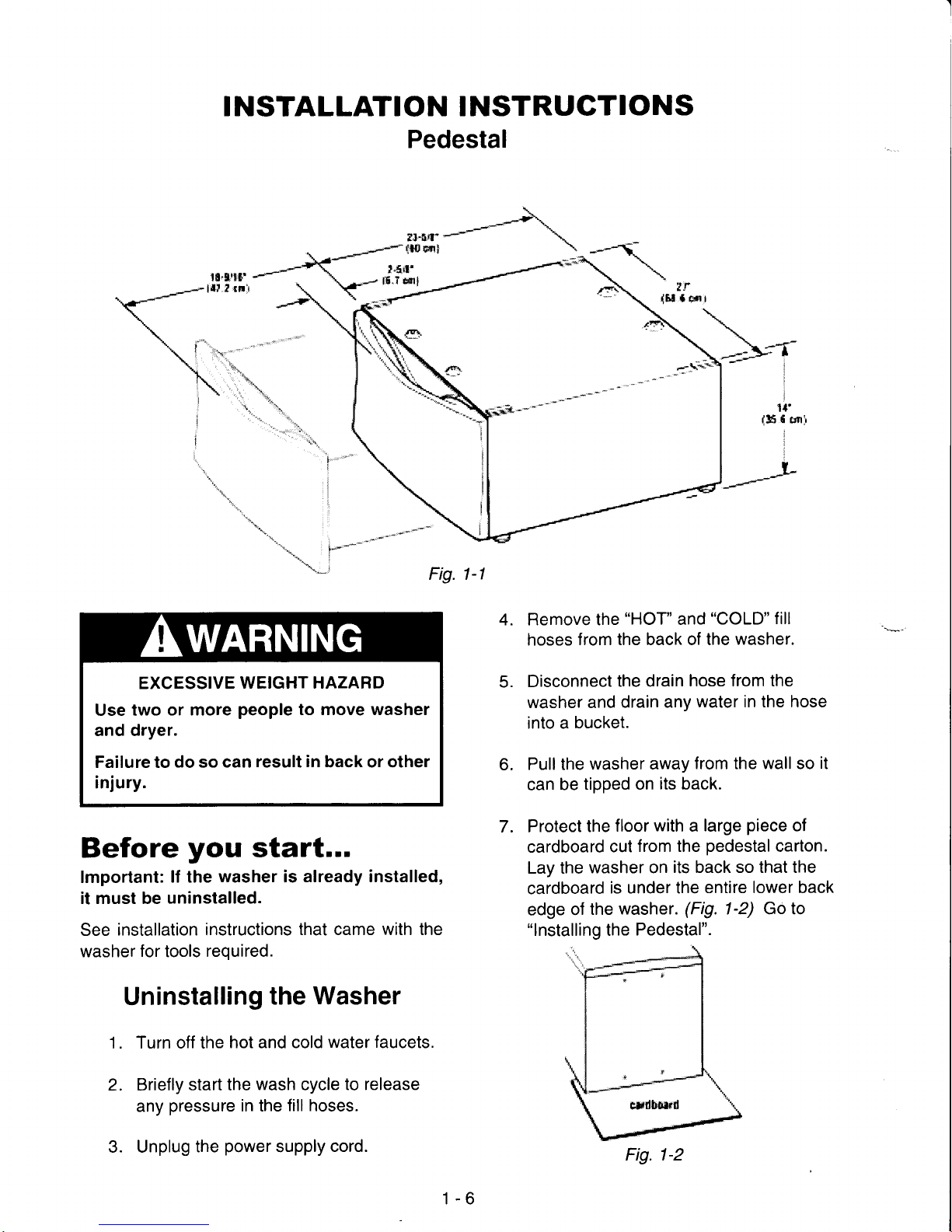
I NSTALLATION I NSTRUGTIONS
Pedestal
til.gr*f'
l{t.t
!tlr
t.5ct'
l5^7
tf,l1
:h.
..1;.;
1".
rT
i
i
i
1l'
{5
f
ctrri
Remove the
"HOT"
and
"COLD"
fill
hoses
from the back of the
washer.
Disconnect
the drain
hose from the
washer and
drain any
water in the hose
into a
bucket.
Pull the
washer away
from the wall so
it
can
be
tipped on
its back.
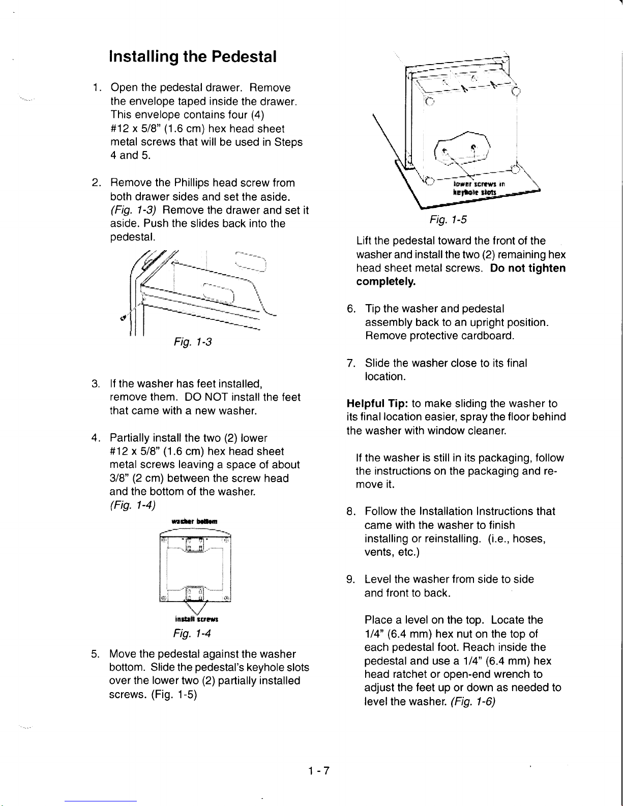
Protect
the
floor
with a large
piece
of
cardboard
cut
from the
pedestal
carton.
Lay the
washer on
its back so that the
cardboard
is under the
entire lower back
edge
of
the
washer.
(Fig.
1-2) Go to
"lnstalling
the
Pedestal".
-l
'o\*l*---
Fig. 1-l
4.
5.
6.
7.
2.
EXCESSIVE
WEIGHT HAZARD
Use two
or more
people
to move washer
and dryer.
Failure to
do
so
can
result in
back or other
injury.
Before
you
start...
lmportant:
lf the
washer
is
already installed,
it must be uninstalled.
See
installation instructions
that came with the
washer
for
tools
required.
Uninstalling
the Washer
1. Turn off the
hot and cold
water faucets.
Briefly
start the
wash
cycle
to release
any
pressure
in the
fill hoses.
Unplug
the
power
supply
cord.
3.
1-6
Fig. 1-2
Page 11
1
t.
Installing
the Pedestal
Open
the
pedestal
drawer. Remove
the envelope taped inside
the drawer.
This envelope
contains four
(4)
#12x
5/8"
(1.6
cm) hex
head sheet
metal screws
that will be
used in Steps
4
and 5.
Remove
the
Phillips
head
screw from
both drawer
sides and set
the aside.
(Fig.
1-3) Remove
the drawer
and set it
aside. Push the
slides back into the
pedestal.
Fig. 1-3
lf the washer has feet
installed,
remove
them. DO NOT install
the feet
that came
with
a new washer.
Partially install the
two
(2)
lower
#12 x
5/8"
(1
.6 cm) hex head
sheet
metal screws leaving
a space of about
318"
(2
cm) between
the screw head
and the bottom of the washer.
(Fis.
1-4)
Move
the
pedestalagainst
the
washer
bottom. Slide the
pedestal's
keyhole
slots
over the
lower
two
(2) partially
installed
screws.
(Fig.
1-5)
Fig. 1-5
Lift the
pedestal
toward
the front of the
washer and
install
the two
(2)
remaining hex
head sheet metal screws. Do not tiqhten
completely.
6.
Tip
the
washer
and
pedestal
assembly back to an
upright
position.
Remove
protective
cardboard.
7. Slide the washer close
to
its final
location.
Helpful
Tip:
to
make
sliding the
washer
to
its
final location
easier, spray the
floor
behind
the
washer with window
cleaner.
lf the
washer
is still in its
packaging,
follow
the instructions on the
packaging
and
re-
move it.
8.
Follow
the
Installation
lnstructions that
came with the washer to finish
installing or reinstalling.
(i.e.,
hoses,
vents,
etc.)
9. Level the
washer
from side to side
and front to back.
Place a
level
on the top. Locate the
114"
(6.4
mm) hex nut on the top of
each
pedestal
foot. Reach inside
the
pedestal
and use a 114"
(6.4
mm) hex
head ratchet or open-end wrench to
adjust the
feet
up or down as needed to
levelthe washer.
(Fig.
1-6)
z.
4.
rir|ltr
!*lm
lN!r*firn|
Fig. 1-4
1-7
Page 12
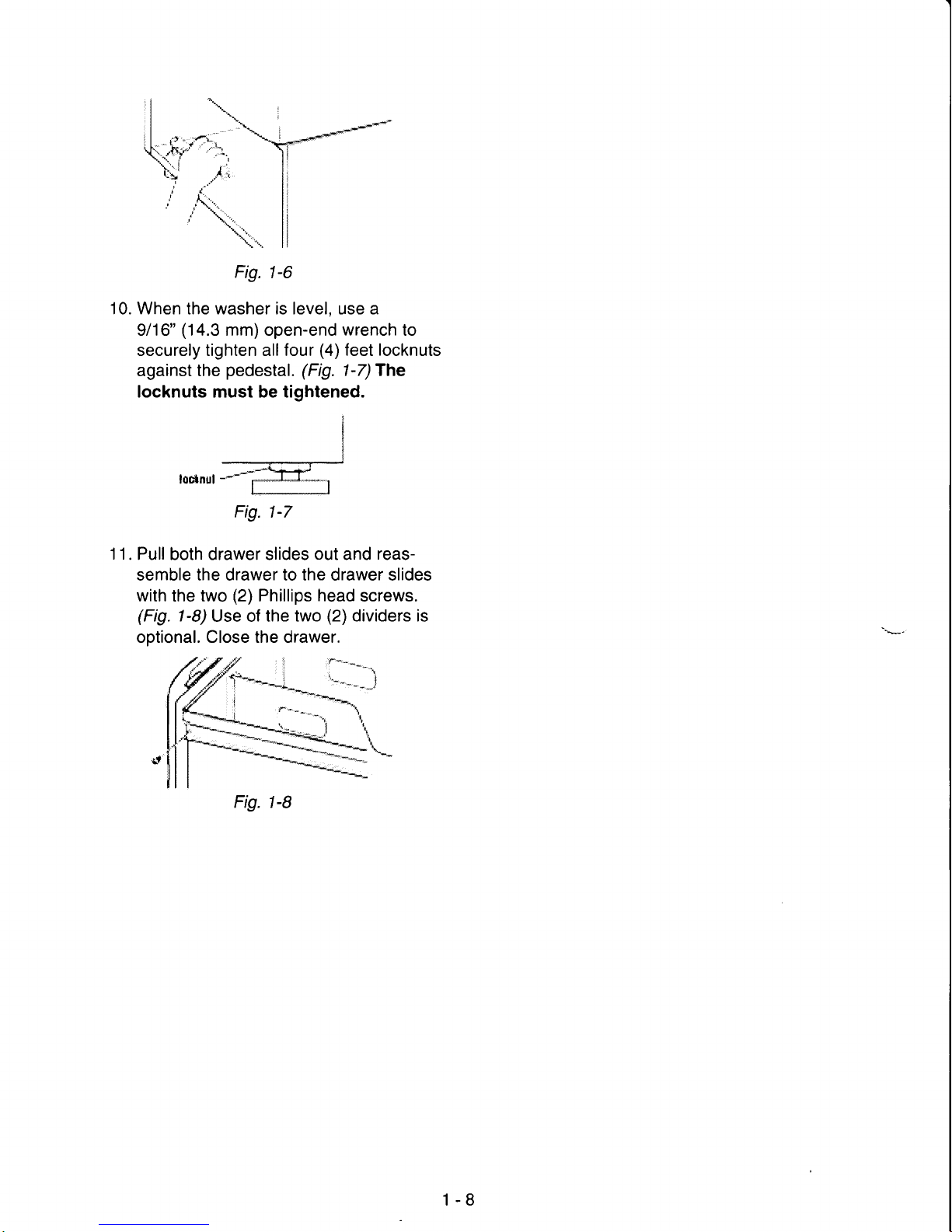
Fig.
1-6
10. When the washer is level, use a
9/16"
(14.3
mm) open-end
wrench
to
securely tighten all four
(4)
feet
locknuts
against the
pedestal. (Fig.
1-7)The
locknuts must be tightened.
loc*nul
----l
11.
Pull both drawer slides
out
and
reassemble the drawer to the drawer slides
with
the
two
(2)
Phillips head
screws.
(Fig.
1-8)
Use of the two
(2)
dividers is
optional. Close the drawer.
Fig.
t-7
Fig. t-8
1-8
Page 13
SEGTION
2
THEORY
OF OPERATION
INTRODUCTION
The HFand HEt Front-Loading
Automatic
Washers
present
a number of
new features
and
operating
characteristics
quite
different from
previous
models.
In
addition to the
introduction
of front-loading
operation, the HF and HEt
contain a number
of unique operating
features
designed to increase
clothes
cleaning ability while
offering
very
high water
and energy
conservation.
Water
System
The HFandHFt water
system
consists of the hot and cold water
inlet valves, a water
temperature
sensor, a water flowmeter
and control and the
dispenser
distribution system along with a
traditional
pressure
switch.
Water Inlet Valves
-
The hot
and cold
water inlet valves
are located
at the back of the
washer. These valves receive
a control
signalfrom
the Central Control Unit to manage
the temperature of
incoming water. The
temperatures
are determined
by the specific wash cycle
selected and a temperature
sensor located in
the wash tub.
To improve
cleaning of heavily
soiled clothing and to
provide
a sanitizing
feature,
the water
tempera-
ture can
be
increased
through the use of a heating
element
located in the bottom of the tub,
(HFt
model
only).
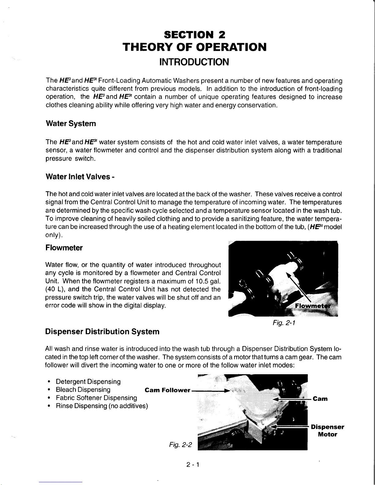
Flowmeter
Water flow,
or the
quantity
of water introduced
throughout
any cycle is monitored
by a
flowmeter
and Central Control
Unit. When the flowmeter registers
a maximum of 10.5
gal.
(40
L), and
the Central Control Unit has not
detected the
pressure
switch trip, the
water
valves will
be shut off and an
error code will
show
in
the digital display.
Dispenser
Distribution
System
All
wash and rinse water is introduced into
the wash tub through a
Dispenser Distribution
System lo-
cated in the top left
corner of the
washer.
The system consists of a
motor that
turns a cam
gear.
The cam
follower willdivert
the
incoming
water to one
or
more
ol
the follow water
inlet modes:
.
Detergent Dispensing
.
Bleach Dispensing
.
Fabric
Softener Dispensing
.
Rinse Dispensing
(no
additives)
Gam Follower-->'a
Fig.2-2
Dispenser
Motor
Fig.2-1
2-1
Page 14
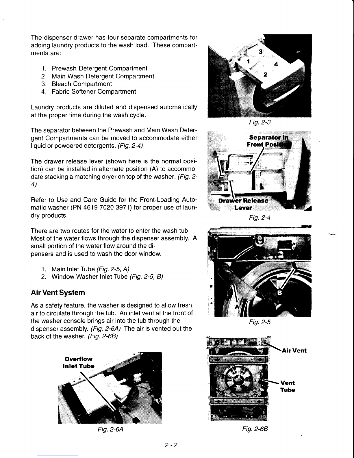
The dispenser drawer
has four separate compartments
for
adding
laundry
products
to the
wash load.
These compart-
ments
are:
1.
Prewash
Detergent Compartment
2. Main Wash Detergent Compartment
3. Bleach Compartment
4. Fabric Softener Compartment
Laundry
products
are diluted and dispensed automatically
at the
proper
time during
the wash cycle.
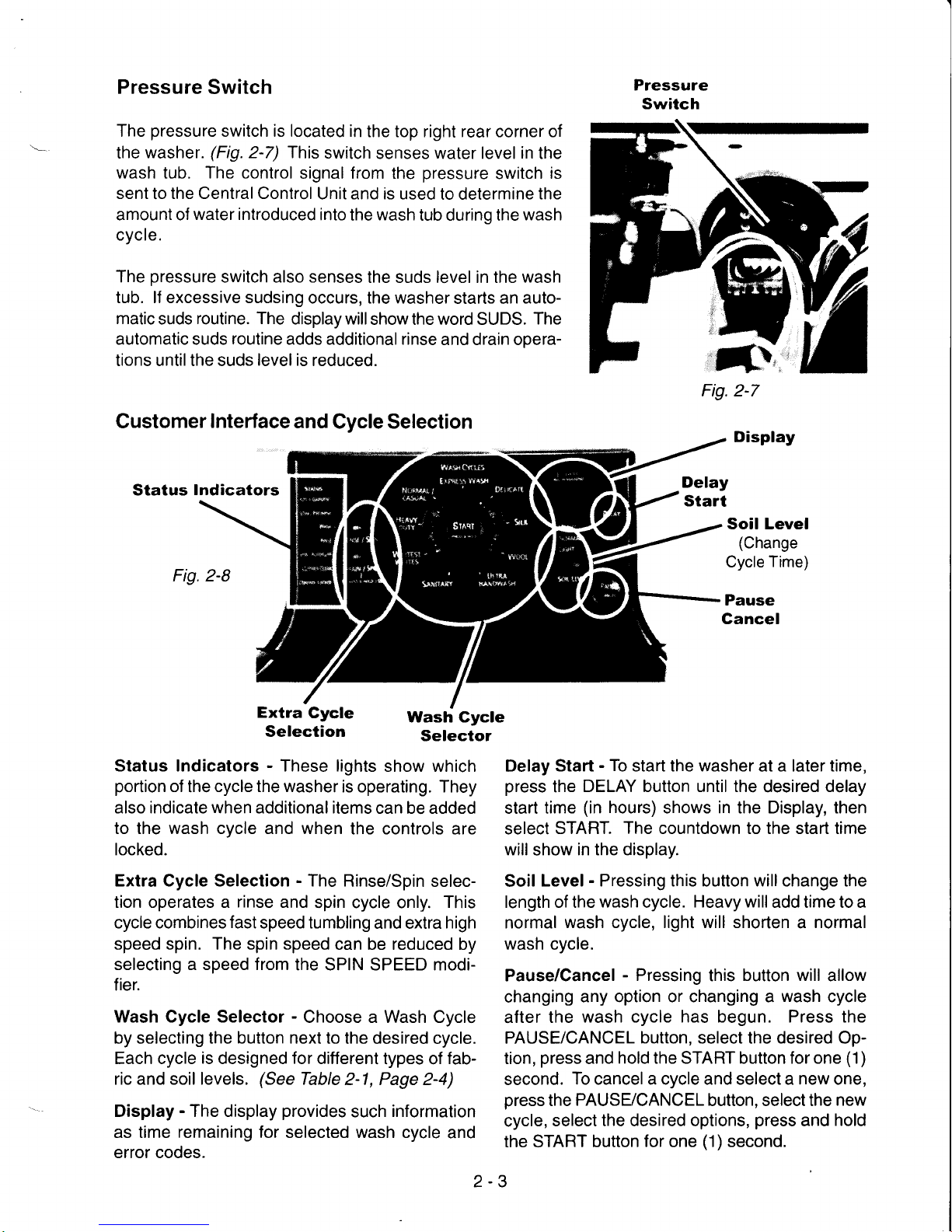
The separator between
the Prewash and Main Wash Deter-
gent
Compartments
can be
moved
to accommodate either
liquid
or
powdered
detergents.
(Fig.2-a)
The drawer
release lever
(shown
here is the normal
posi-
tion) can be
installed in alternate
position
(A)
to accommo-
date stacking
a
matching dryer on
top of
the washer.
(Fig.
2-
4)
Refer
to
Use and Care Guide
for
the
Front-Loading Auto-
matic washer
(PN
4619 7020 3971) for
proper
use of
laun-
dry
products.
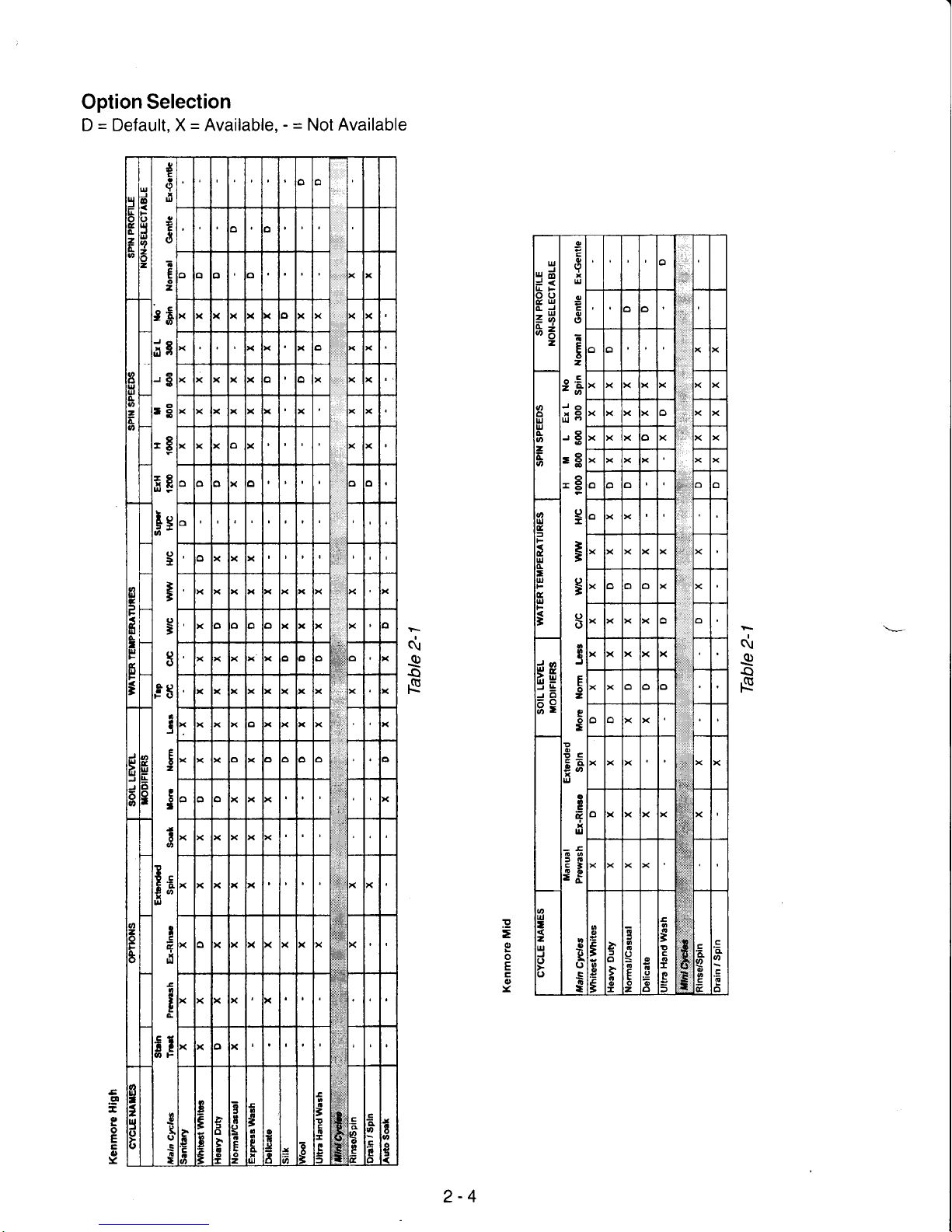
There are two
routes for the water to enter the
wash
tub.
Most
of the
water
flows through the dispenser assembly.
A
small
portion
of the
water flow
around
the di-
pensers
and
is used to wash the door
window.
1.
Main
Inlet Tube
(Fig.2-5,
A)
2.
Window Washer Inlet Tube
(Fig.
2-5, B)
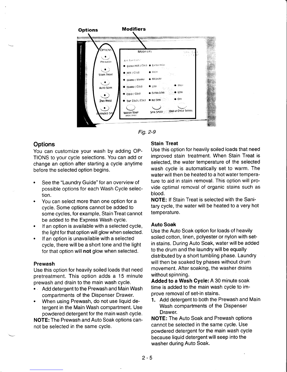
Air Vent
System
As a safety
feature, the washer
is
designed to allow
fresh
air to circulate through
the tub.
An
inlet vent at the
front of
the
washer
console
brings air
into
the tub
through the
dispenser assembly.
(Fig.
2-6A) The
air
is vented
out
the
back of
the washer.
(Fig.
2-68)
AirVent
Fig.2-3
*tr
Dravver
Releaso
Fig.2-a
Fig.2-5
Fig.2-64
2-2
Fig.2-68
Page 15
Pressure
Switch
The
pressure
switch is located in
the top right rear corner of
the
washer
(Fig
2-7) This
switch
senses water level
in
the
wash tub. The control
signal from the
pressure
switch
is
sent
to
the Central Control
Unit and is used
to determine
the
amount of
water introduced
into
the
wash
tub durino the
wash
cycle.
The
pressure
switch also senses
the suds level in the
wash
tub. lf excessive sudsing
occurs, the washer
starts an
auto-
matic
suds
routine. The
display will
show the word SUDS.
The
automatic suds
routine
adds additional rinse
and drain opera-
tions untilthe suds
level is
reduced.
Customer
Interface
and
Cycle Selection
Status
Indicators
Fig.2-B
Pressure
Switch
Display
Delay
Start
Soil Level
(Change
Cycle
Time)
Pause
Cancel
Delay
Start
-
To
start the washer
at
a later time,
press
the
DELAY button until the
desired
delay
start time
(in
hours)
shows in the Display, then
select
START.
The
countdown to the start time
will
show
in the display.
Soil
Level- Pressing this button willchange the
length of the
wash
cycle.
Heavy will
add time to a
normal
wash cycle, light will shorten a normal
wash
cycle.
Pause/Cancel
-
Pressing
this
button will
allow
changing
any option or changing a
wash
cycle
after
the
wash cycle has begun. Press the
PAUSE/CANCEL
button,
select the desired Op-
tion,
press
and
hold the START button for one
(1)
second.
To cancel a cycle and select a new one,
press
the
PAUSE/CANCEL
button, select the
new
cycle,
select the desired options,
press
and
hold
the START
button for one
(1)
second.
Extra
Gycle
Selection
Wash Cycle
Selector
Status Indicators - These lights
show which
portion
of
the
cycle the washer
is operating. They
also indicate when additional items
can be added
to the wash cycle and when
the controls are
locked.
Extra Cycle Selection - The
Rinse/Spin selec-
tion operates a
rinse
and
spin cycle only.
This
cycle combines
fast
speed tumbling
and extra
high
speed
spin. The spin speed
can be reduced by
selecting a speed from
the SPIN SPEED modi-
fier.
Wash Cycle Selector
-
Choose a Wash Cycle
by selecting the button next to
the desired cycle.
Each cycle
is
designed
for
different
types of
fab-
ric and soil levels.
(See
Table
2-1, Page 2-4)
Display - The display
provides
such
information
as time
remaining for
selected wash cycle
and
error codes.
Fig.2-7
2-3
Page 16
Option Selection
D
=
Default, X = Available,
-
=
Not Available
cir
e
a
N
e\l
e
a
N
=
E
o
x
2-4
U
,1
d
=<
IF
)a
IU
LJ
=u
;6
2
g
o
q
U
I
o
(,
t
F
6
-
..E
-A
-6
J6
rO
,t
.$
o
+o
e
t
t
o
o
,
3
E
2
e
o
-
o
9C
c6
u
a
o
t
E
!l
=o
sti
-d
a
!.
()
E
I
.lJ
',.ti
,u
.,i
ti
i,
'v
,'
n
!
I
n
a
L
n
x
(
(
x
) x
x
l
3
o
U
E
(
I
U
t
ll,
t
[l
t
l
4o
;s
J+
{8
6'
(
l
t,
u
I
(
I
!
J
J
)
c
I
o
E
I
o
o
I
E
o
J
o
2
o
o
1
E
o
P
)
D
Y
q
o
I
z
z
D
U
J
o
o
U
d
cl
z
-
.1
c
I
U
g
c
d
a
E
o
z
'^c
'E
-o
iE
o
J6
r!
-E
$F
Ie
()
t
E
o
-
t?
o
FE
5
I
E
2
e
I
t
t
6
e
o
t
c
4
u
E
o
I
A
iE
att
P
c
3
o
C
G
t
I
a
E
l,
in
l
l
f
l
D
n
!
I
E
n
x
f
a
(
l
f
)
n
g
I
i
I
L
I
U
!
t
l
(
( ( (
(
l
(
l
(
w
l;it
:ajt),,
'.n,,
tlit
(
x
(
J
c
J
J
)
D
D
I
g
I
3
( (
l
f
I
(
n
i
(
(
ru
w
(
( (
(
)
3
I
a
2
5
J
J
tr
t
n
I
=
r
E
l
!
E
g
G
n
E
o
2
a
tr
P
D
i
I
i a
5
I
E
E
It
s
i
D
D
e
a
o
E
f
a
I
D
3
I
a
5
.g
E
o
E
E
{,
Y
Page 17
.-"1.i
nt4ti,
11{tAl
'..i--
Artl{l
sildk
.
r')
Iti')
filr',sf
tl
M00ltl!n!
,',:'.'t
a
lrti^
Hrlf /
f(,
1
a I
r'f^!r
'
a ft{}t
i
r:1
lf,
a
ir''
ir
t
fcAlt'l
J
r'r^F['
'
Mrlrr']t''j
a
l4iAti4lf${.ti
a
Lilr.
I
ll'{'fr
a
fst
D
/
{:,)ttl
r
tirfi*
l{1r"
' L{:}ur
a
lAp
f{}rfi I
trf]1.0
a
Iiltl }p,f'l
'
o{1'
,1
L,-"]
\*-i
r*''
woii:iE
*o Sfr1,
ltrftr
['iln
$r
crrl!
5i(N'(r
Modifiers
Options
You can customize
your
wash by adding OP-
TIONS to
your
cycle selections.
You can add or
change
an option
after starting a cycle
anytime
before
the selected
option begins.
.
See
the
"Laundry
Guide"
for
an overview
of
possible
options
for each
Wash
Cycle selec-
tion.
.
You can
select
more than one option
for
a
cycle.
Some options
cannot be
added to
some cycles,
for
example,
Stain
Treat
cannot
be added
to the Express
Wash cycle.
.
lf
an option
is
available
with
a selected
cycle,
the
light
for thatoption
will
glow
when selected.
.
lf an option
is unavailable
with a selected
cycle,
there
will be a short tone
and the light
for that option
will
not
glow
when selected.
Prewash
Use
this option
for heavily soiled
loads that need
pretreatment.
This option adds
a 15 minute
prewash
and drain to
the main
wash cycle.
.
Add detergent
to the
Prewash and
Main Wash
compartments
of the
Dispenser Drawer.
.
When using
Prewash, do
not
use
liquid de-
tergent
in
the
Main Wash compartment.
Use
powdered
detergent
for the
main wash cycle.
NOTE:
The Prewash
and Auto Soak options can-
not be selected
in
the same
cycle.
Stain
Treat
Use this option
for
heavily
soiled
loads that
need
improved
stain
treatment.
When
Stain
Treat
is
selected,
the
water temperature
of the selected
wash cycle
is automatically
set to
warm. The
waterwillthen
be heated to a
hot water tempera-
ture
to aid
in stain
removal.
This
option
will
pro-
vide optimal
removal of organic
stains such as
blood.
NOTE:
lf Stain
Treat is selected
with the Sani-
tary
cycle,
the
water will be
heated to a very hot
temperature.
Auto Soak
Use
the
Auto Soak
option
for loads of
heavily
soiled
cotton,
linen,
polyester
or
nylon
with
set-
in stains.
During
Auto Soak,
water
willbe added
to
the drum
and
the
laundry will be equally
distributed
by
a short tumbling
phase.
Laundry
will then
be soaked
by
phases
without drum
movement.
After soaking,
the
washer drains
without
spinning.
Added
to a
Wash Cycle:
A 30 minute soak
time
is added
to
the main
wash cycle to
im-
prove
removal
of set-in stains.
1.
Add detergent
to both
the Prewash
and
Main
Wash compartments
of the
Dispenser
Drawer.
NOTE:
The Auto
Soak and
Prewash options
cannot
be selected
in
the
same cycle. Use
powdered
detergent
for the
main wash cycle
because
liquid
detergent
will seep
into the
washer
during
Auto Soak.
Fig.2-9
2-5
Page 18
2.
Select a
Wash Cycle.
3. Select AUTO SOAK.
NOTE: For
cycles
with hot wash temperatures,
the soak temperature will be set to
warm;
otherwise, the soak temperature
will
be the
same as the
wash
temperature.
4.
Select and
hold START
(approximately
1
second). After soaking,
the
washer
drains
and the wash cycle starts.
Without a Wash Cycle: Provides a soak
time
with warm
or cold
water followed by drain.
1.
Add detergent only to
the Prewash compart-
ment
of the
Dispenser Drawer.
2. Select DRAIN/SPIN or
RINSE/SPIN first.
then AUTO SOAK.
3. Choose the desired
soak temperature.
4.
Select and
hold START
(approximately
1
second).
2nd Rinse
A
second
rinse can be used to ensure the
removal
of detergent or bleach
residue from
garments.
This
option
provides
an additional
rinse with the same water temperature as the
first rinse.
Extended
Spin
Use this option to add
an additional spin to any
cycle to improve the
"fluff"
of
your
laundry, to
reduce
drying time,
and to save energy.
Modifiers
Preset
cycle settings
of Water
Temperature,
Wash/Rinse, and Spin Speed
can be changed.
You
can change a
modifier after starting a cycle
anytime before the selected
modifier begins.
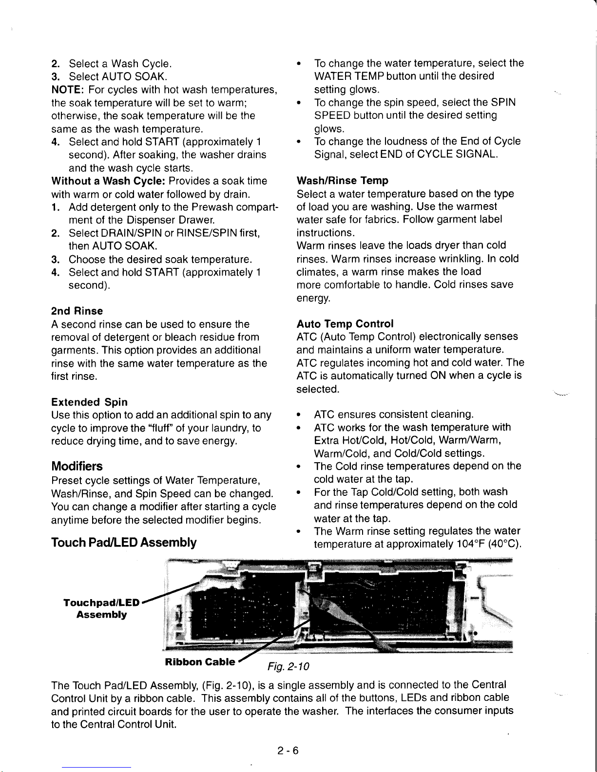
Touch
Pad/LED
Assembly
.
To change the
water temperature, select the
WATER
TEMP button
untilthe desired
setting
glows.
.
To change the
spin speed, select
the SPIN
SPEED
button until the
desired setting
glows.
.
To change the
loudness of the
End of Cycle
Signal,
select
END of CYCLE SIGNAL.
Wash/Rinse
Temp
Select
a
water
temperature
based on the type
of
load
you
are
washing. Use the
warmest
water safe
for fabrics.
Follow
garment
label
instructions.
Warm
rinses leave the
loads dryer than
cold
rinses. Warm
rinses increase
wrinkling. In cold
climates,
a
warm rinse
makes the load
more comfortable
to
handle. Cold rinses save
energy.
Auto
Temp Control
ATC
(Auto
Temp
Control)
electronically
senses
and
maintains a
uniform
water temperature.
ATC
regulates incoming
hot and cold
water. The
ATC is automatically
turned ON
when a cycle
is
selected.
.
ATC ensures
consistent
cleaning.
.
ATC works
for the
wash
temperature
with
Extra
HoVCold,
HoVCold,
WarmMarm,
Warm/Cold, and
Cold/Cold
settings.
.
The Cold
rinse temperatures
depend on the
cold
water
at
the tap.
.
For the
Tap
Cold/Cold
setting,
both
wash
and rinse temperatures
depend on the
cold
water at
the tap.
.
The Warm
rinse setting
regulates the
water
temperature
at approximately
104"F
(40'C).
Touchpad/LED
Assembly
Ribbon Gable
Fig.2-10
The Touch Pad/LED
Assembly,
(Fig.
2-10), is a single assembly
and
is connected
to the Central
Control Unit by a ribbon cable.
This assembly contains
all of the buttons,
LEDs and
ribbon cable
and
printed
circuit boards
for
the user to
operate the
washer.
The interfaces
the consumer
inputs
to the Central Control
Unit.
2-6
Page 19
Central
Control Unit
(CCU)
The Central
Control Unit is located at
the top
rear
of the
washer
and is
enclosed in a control box.
(Fig.
2-1 1) There
are
no
serviceable
parts
inside
the control box.
lf
diagnostic tests
indicate
any component of the
CCU
is
defective, the entire
control
box
must
be
replaced.
The
CCU receives input lrom
the touchpad/LED assembly
and directly
controls the dispenser, drain
pump,
water inlet
valves,
door
locking
and unlocking solenoids,
and
heating
element relay. The
CCU
monitors
the
pressure
switch,
flow-
meter,
temperature sensor and
door
lock
switches.
The
CCU sends the customer
selection
input
to the
Motor
Control Unit for
proper
motor operation.
Motor
Gontrol Unit
(MCU)
The Motor
Control Unit is located is inside
a
plastic
control
box located in
the
lower front
corner of the washer cabinet.
(Fig.
2-12) The control box is shown with
the access
door
open.
The MCU
operates the drive motor
at
varying
speeds
and
direction based on inputs received
by the CCU to complete
the cycle selected. The MCU also monitors
a tachomeler
on the motor
to confirm that the drive motor is
operating
at
the
proper
speed and direction.
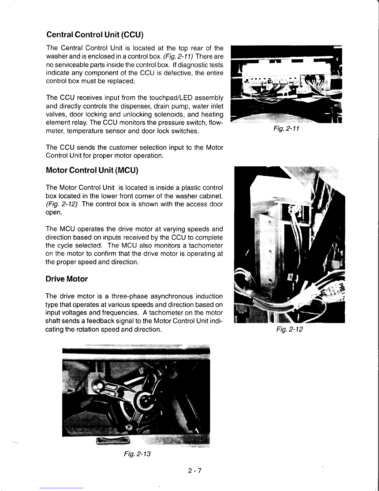
Drive Motor
The
drive motor is a three-phase
asynchronous
induction
type
that operates at
various
speeds and direction based on
input
voltages and frequencies. A
tachometer on the
motor
shaft sends a feedback
signal to the
Motor
Control Unit
indi-
cating the rotation
speed and direction.
Fig.
2-11
Fig.2-12
Fig.2-13
2-7
Page 20

Pump Motor
A
separate
pump/pump
motor is
used to
drain the wash
lub.
(Fig.
2-14) The
pump
motor is 120 VAC
and is at-
tached directly to the
pump.
The
pump
has
a clean-out
filter located
at the
front
that allows
for
the
removal
of
large
objects that
may have
passed
from the drum.
(Fig.2-15)
Eco Valve
The washer has a specially designed
valve
that closes
during the
wash
portion
of the cycle so that 100% of the
water
and detergent
mixture is used
on
the wash load.
The Eco Valve
insures
that
no water
or detergent
is
wasred.
(Fig.
2-1a &
2-16)
Suspension System
The wash
tub
is held in its horizontal
position
with four
pneumatic
shock absorbers attached to
the
bottom
four
corners of
the tub assembly.
In
addition, the
wash
tub
is
suspended
from the top frame of the washer
with
two springs attached to the sides of the
unit.
Stability
for
this
suspension system
is
provided
by
three
concrete
counter
weights.
Two are
located
at the
front of the wash tub. One
is
positioned
at
the back of
the
tub. These
counter
weights eliminate the need for
the traditional balance ring.
(Fig.
2-1 7)
Counter
Weights
(3)
Fig.2-16
Shock
Absorbers
(4)
Fig.2-17
Drain
Pump
Fig.2-14
Fig.2-15
2-8
Page 21

Heating Element and Temperature
Sensor
Model HF
provides
a
heating
element
to
increase
the
water temperature
during certain
wash cycles. The temperature
sensor is
used
with
the
heater to monitor water
temperature in
the tub.
(Fig.
2-18)
Fig.2-18
Door Lock/Switch Assembly
The
Door
lock/Switch Assembly
is located
on the
right
side of
the door
opening.
(Fig.2-19
& 2-20)
The
assembly
contains a latching mechanism
that will electrically lock the
door during certain
operations in a
wash
cycle.
Heating Element
Relay
A relay
is
used to turn the
heating
element
on
and off.
The
heating
element relay is located in
the
lower right-hand
side of the
washer
cabinet.
(Fig.2-21)
The
CCU operates a solenoid to
close
the main
relay
contacts,
providing
120
VAC
to
the heating element.
Heating
Element
Solenoid
Fig.2-21
Panel
Interlock
Switches
The
front and rear
interlock
switches
(Fig.
2-22)
are
located
immediately behind
the toe and rear
panels
of the washer.
The
switches
provide
a
grounding
circuit
to the drive motor
and
heating
element,
when
either
panel
is removed for
ser-
vicing.
Fig.2-19
Fig.2-20
2-9
Fig.2-22
Page 22

VENT HOSE
-
CONSOLE
F
TUB
ASSEMBLY
i
DRIVE
MOTOR
Section
Three
GOMPONENT
ACCESS
COMPONENT LOCATION
DETERGENT
DISPENSER
PULLEY
DRAIN PUMP
ASSEMBLY
HEATING
ELEMENT
IELAY
WASHER
BACK
WASHER FRONT
MOrOR/l
CONTROL
UNIT
{
3-1
Page 23

Required Tools
The
Source
1 10
sizes, Torx T-15,
hammer.
COMPONENT
ACCESS
Front Loading Washer requires
the use of
Metric Socket
Wrenches
of
various
T-20 and T-25 Drivers, a Crescent Wrench, a
flat
bladed
screwdriver and a
ACCESSING
COMPONENTS
IN THE
CONSOLE
Components accessible in the Console include
the Console
Cover and
the Touch Pad/LED Assembly.
Access
to
these components requires that the
top of the
washer be
removed.
Removing
the
Washer Top
Three screws secure the washer top at the back
of
the
washer. Remove
the three
screws
and
lift
the top from the
washer.
(Fig.
3-4)
'I
f''l
lN,
*:irKKrkl:'ffiff :;,,.*;*
'f,.$
Fig.3-4
Removing the Console
from
the Cabinet
Disconnect the
Touch Pad/LED Assembly ribbon
connector
from
the
left
side of the Central Con-
trol Unit
(Fig.3-5)
and
release
it
from
the
wiring
harness
brackets on
the right side of the washer
top.
Ribbon
Gonnector
Remove the detergent
dispenser drawer by
pressing
down on the
release tab at the back of
the drawer
(Fig.3-6)
and
pulling
it completely out
of the
washer.
Gonsole
Release Tab
Fig.3-O
Once the drawer
is removed,
remove the screw
in
the
recessed
hole next to the drawer opening.
Release the tab securing
the
right
side of the
con-
sole
to the
washer and
remove
the console.
Be
sure the
ribbon cable clears the
cabinet frame.
Removing the
Touch Pad/LED
Assembly from
the Console
The Touch
Pad/LED Assembly
is
a single
unit and
contains
the
Push Buttons, LEDs, cable,
etc.
Re-
place
the entire
assembly
if any components are
defective.
Touch Pad/
Gonsole Gover
Fig.3-7
Drawer
Release Tab
Screws
Fig.3-5
3-2
Page 24

There
are nine
tabs securing the Touch Pad/LED
Assembly
to the console.
(Fig.
3-9)A
flat
bladed
screwdriver will
be
helpful
in releasing
these tabs.
Typical Release Tab
Fig.3-8
REMOVING THE
WASHER
The washer
door
can be
removed
by
removing
the
two screws securing the door hinge
to the
washer front
and
lifting
upward.
Fig.3-10
Access
to the
door switch
requires
that the water
seal boot
be
removed from
the front of the washer.
(Fig.
3-17,) Use a flat bladed screwdriver
at the
location
of the retainer
spring and
pull
the
retainer
forward
and then off the
perimeter
of the
boot.
Release
these tabs
in
sequence from left
to
right
around
the Touch Pad/LED Assembly
until allof
the tabs are
free
and the Assembly can
be
lifted
from
the console.
(Fig.3-9)
Tab
Tabl
DOOR AND DOOR SWITCH
Ease the edge of the boot off of the lip of the
washer front near the
door switch.
(Fig.
3-12)
Remove
enough
of the
boot
to
gain
access to
the door switch
behind the washer front
panel.
Boot
Pulled
Back
Fig.3-12
The door switch is secured to the
washer
front
panel
with three screws. Once these screws are
removed,
the
door switch will remain in
place
until
it
is
lifted slightly and
pulled
back
from
the
washer
front
panel.
Retainer
Spring
Fig.3-9
Screws
Fig. 3-t 1
3-3
Fig.3-13
Page 25

REMOVING THE
WASHER
FRONT
PANEL
Removing
the
washer
front
panel
will require that
the
door switch be
removed and the boot be sepa-
rated
completely
from the
front
panel
opening.
The
console
must also be
removed.
Next,
remove the three screws
securing the toe
panel
to
the front of the
washer
(Fig.
3-1a)
and
remove the tow
panel
by
lifting slightly and
pull-
ing
forward.
,
_rF
,**ru-**--,**,_
.-**
Screws
Fig.3-14
Remove the two screws
securing the bottom
of
the
front
panel
to the
washer, and the
two screws
securing the top of
the
front
panelto
the
washer.
The front
panel
can
now be
removed from the
washer.
(Fig.
3-15)
REMOVING
THE BOOT
FROM
THE TUB
ASSEMBLY
The
boot can
be completely
removed
from
the
outer rim
of the tub
assembly.
Carefully
pull
the boot
from around the
water in-
let and
window
washer tubes.
Remove the boot
re-
tainer clamp
by
loosening the clamp
screw
located
at the
upper
right of the tub
opening.
The
boot
can
now be
removed
from the tub.
REPLACING
THE BOOT
AND DOOR
SWITCH
When
replacing
the boot
and
washer front
panel,
special care
must be
taken to assure
a
proper
water seal
and operation.
Carefully
pull
the
nozzle from the
window
washer
tube. Separate
the
plastic gasket
ring
from
the
nozzle.lnsert
the nozzle through
the
hole
in the
boot and
slide the
plastic gasket
ring down
the
shaft of the
nozzle so
that the
boot
is securely trapped
between the
gasket
ring
and the
nozzle
ridge.
Insert the nozzle
shaft
into the
window
washer inlet tube and
insert the end
of the
water
inlet tube
into the
boot.
Fit the boot
around
the
front lip of the tub
so it
rests smoothly
and
evenly.
Fit the boot
clamp
around
the front
lip of the
tub and tighten
the
screw.
Be careful
not to over
tighten
this
screw
Damage to
the boot clamp
or the boot
could occur.
When
reinstalling
the
door switch,
be sure to
insert the
two tabs
on the
right side of
the
switch
assembly
into the slots
in the
plastic
wiring
harness
guide.
Failure to do this
will
result
in
unwanted
noise
while
the
machine
operates.
Screws
Fig.3-15
3-4
Page 26

REMOVING
THE DETERGENT
DISPENSER ASSEMBLY
The
Detergent
Dispenser
Assembly is located
under the washer
top.
Begin
by removing
the
washer top,
console and
front
panel.
Separate the water inlet
and
window washer
tube
from
the boot.
Pullthe
water inlet tube from the outlet
connector
of the detergent dispenser.
(Fig.
3-16)
NOTE: When reinstalling the water inlet
tube,
wet
the
water inlet
gasket
on the detergent dis-
penser
with water only. Do not use any
other
lu-
bricant. Align the locator nib on
the
water inlet
tube with the indentation on
the dispenser con-
nector
and slide the tube onto the detergent dis-
penser
assembly.
Remove
the screw securing the front of the
detergent dispenser assembly to the top front f rame
member.
(Fig.3-16)
Water lnlet
Tube
Fig.3-16
Disconnect the overflow
hose f rom
the detergent
dispenser
assembly.
(Fig.
3-17)
Remove the screw securing the detergent
dis-
penser
assembly to
the top left frame member.
(Fig.
3-17) Slide the assembly back slightly and
lift the assembly
out.
Vent
Tube
To remove the detergent dispenser
motor assem-
bly,
lift
the cam
follower from the diverter cam
and
rotate
the
diverter cam clockwise to access
the motor mounting
screws.
Sclews
(Under
Gam)
Fig.3-18
f"
i'
tt
i"
t
Fig.3-17
Screw
3-5
Page 27

REMOVING THE
MAIN
CONTROL
BOX
AND PRESSURE
SWITCH
The main
control box
is
a single assembly and
does not
contain any serviceable
parts.
lt
can be
removed
by
lifting
the top
plastic
tabs securing
it
to the back
cabinet
frame
and
sliding it towards
the front
of the
washer.
(Fig.
3-19)
Tabs
ro remove,n"
p,".L11.1,1,'n.n,
rirst remove
the
wiring harness retainer from
the
side of the cabi-
net.
(Fig.
3-20)
rhendisconnectr^:t;,::rt^arnessconnecrors
and the
pressure
hose and turn the
pressure
switch counterclockwise to release
it from
the
cabinet.
(Fig.
3-21)
Pressure Switch
REMOVING
THE DRIVE MOTOR
The
drive
motor can be
removed once the back
panel
has
been
removed.
Twelve screws secure
the back
panel
to the
washer. Remove the
12
screws
and remove the
back
panel.
Remove the Drive
Belt.
Disconnect
the wiring harness connectors and
ground
wires from the drive
motor
terminals.
Push
the
wiring harness tie
from the motor
mounting
bracket.
Remove the
mounting bolt securing the
motor
to
the tub.
(Fig.3-22)
Fig.3-22
REMOVING THE
PUMP ASSEMBLY
The
pump
assembly can
be accessed once the
toe
panel
has
been
removed.
To
clean
out the
large item
filter,
turn the
large
knob
counterclockwise
and
pull
it
out.
(Fig.
3-23)
Fig.3-23
Fig.3-21
3-6
Page 28

To remove
the
pump
assembly, begin by opening
the door covering the wiring harness connector
and
disconnect
the
wiring harness from
the
pump
motor terminals. Remove
the screw securing the
pump
assembly to the washer frame.
(Fig.
3-24)
Once the
pump
is removed the drain hose
and
tube outlet hose can be removed.
ACCESSING THE
MOTOR
CONTROL UNIT
Access to the Motor Control Unit may require
removing the left
front
shock absorber.
Using a
flat
bladed screwdriver,
lift
up on the
plastic
tab under the
front right
corner of the
motor
controller
box.
(Fig.
3-26 - INSET)
Fig.3-24
REMOVING THE
SHOCK
ABSORBERS
The
tub
is held in
position
by
four
shock
absorb-
ers, two
in front
(Fig.
3-25)and two at the back.
Each
shock absorber can be disconnected
from
the tub by turning the top of the shock mount
counter clockwise. 90".
The
shock can be
re-
moved from
the
washer
by
turning the
bottom
shock mount counterclockwise. 90'.
Fig.3-25
Fig.3-26
Slide the box
forward
to
release the two tabs at
the back of the box
from
the bottom
panel
of the
washer.
(Fig.3-27)
Fig.3-27
Open the door
on the control box to access to
the test
points
of
the Motor Control Unit.
(Fig.
3-
28)
3-7
Fig.3-28
Page 29

REMOVING THE HEATING ELEMENT
AND TEMPERATURE
SENSOR
Disconnect
the
wiring harness
connectors
from
the heating
element
terminals
and
loosen
but do
not remove the 10-millimeter nut between
the
heating
element
terminals.
(Fig.
3-29)Then slide
the heating
element
from the tub. Slide the
tem-
perature
sensor
from
the
heating
element bracket.
Temperature
Sensor
lOmm Nut
REMOVING THE
TUB
AND DRUM ASSEMBLY
There
are three concrete
weights
attached to the
tub
assembly.
All three must be removed for
safe
removal
of the
tub assembly.
Access to the
weight
on the top
front
of the tub
requires removing the six screws
securing the
top front frame
member from
the
washer
and re-
moving the frame member.
(Fig.
3-30A)
Fig.3-304
Access
to
the weight on the top back of the tub
requires removing the two screws securing the
top
frame
member to the
washer
and
removing
the frame member.
(Fig.
3-308)
Top
Frame
(Back)
secured to the tub by three
13-
(Fig.
3-31)Remove the
three
weight from the
tub.
Bolts
Bolts
Fig.3-31
nuts
from
the tub
for safekeep-
Each
weight is
millimeter bolts.
bolts and
lift the
Remove the
flat
ing.
(Fig.
3-32)
Top Frame
(Front)
Fig.3-32
Fig.3-308
3-8
Page 30

The
tub
is
held
in
position
by
four
shock
absorb-
ers, two in f ront
(Fig.
3-33)
and
two at the back.
(Fig.
3-34)Each shock absorber can be discon-
nected f rom
the tub by turning the top of the
shock
mount counter clockwise, 90o. The
shock can
be removed from
the
washer by
turning the bot-
tom shock mount counterclockwise,
90'.
Remove the screw securing the left end of
the
pressure
tube connector to the tub. Then,
press
down on the
plastic
tab securing the
right
end of
the
pressure
tube connector and
pull
it from
the
tub.
(Fig.3-35)
Pressure
Tube
Gonnector
Removed
Fig. 3-35
Disconnect the
vent hose
and
outlet hose from
the tub.
Remove the top end of the suspension
springs
from the
hanger slot in the top cabinet frame. To
release
the
spring at the
right
side of the cabinet,
it may
be
necessary to remove the
wiring har-
ness retainer
from
the cabinet.
Once the
finalspring is released
the tub
is lree
to
be removed
from
the
washer
cabinet.
(Fig.
3-36)
NOTE: Take care
not
to
let
the tub
drop free in-
side
the cabinet. This could result
in
damage to
components
in the cabinet or damage to
the
tub
assembly.
Front Shock
Absorbers
Rear Shock
Absorbers
Fig.3-33
At the
back
of the tub assembly, remove
the belt
from
the drum and
motor
pulleys.
(Fig.
3-34
-1)
To remove
the
pulley
from
the drum,
place
the
handle
of a crescent wrench through the
pulley
and
into
the steel bearing
hub
to
keep
the
pulley
from turning
(Fig.
3-34
-2)
Use a 21-millimeter socket wrench to remove
the
nut securing the
pulley
to the drum.
(Fig.3-34
-3)
Disconnect the
ground
wire from
the bearing hub
with a T-25 Torx driver.
(Fig.
34a
-a)
Fig.3-34
3-9
Fig.3-36
Page 31

The two
piece
tub
is
held together
with a number
of metalclamps which
can be
removed
by
prying
them
off
with a flat
bladed screwdriver.
(Fig.
3-
s7)
The tub can now o" "?o^l^u!oand the
drum
can be
pulled
from
the back half of the tub.
(Fig.
3-38)
Fig.3-38
REASSEMBLING
AND
REINSTALLING THE
TUB ASSEMBLY
When reassembling and
reinstalling the
tub
assembly, take
note of these special
proce-
dures.
1. When reassembling the tub,
be sure
to
install
all
the metal clips all around
the tub.
A hammer may be necessary
to do this.
2. When reinstalling the
heater
element,
be sure
it is inserted
properly
in the
retainer
inside
the
tub.
(Fig.
3-39)
Heater Glip
Fig.3-39
When reinstalling the tub, be sure to
hook the springs
into the holes to-
wards the
front
of the
tub.
A
small
piece
of duct tape
may be
necessary to
hold
the
flat nut
in
place
when replacing the
front bottom con-
crete weighl.
(Fig.
3-40)
",rli''
J.
4.
Fig.3-40
3-10
Page 32

Section Four
COMPONENT TESTING
CENTRAL
CONTROL UNIT
Connector
Location
1.
2.
3.
4.
5.
Pressure Switch
Temperature Sensor
Dispenser Switch/Motor
lnlet Valves
Drain Pump
6. Door
Lock Solenoids
7. Motor Gontrol Unit
Power
8.
Door Lock Main Switches
9.
Heating
Element Relay
1O. Line
Filter
{l.Serial
Gomm
Link
l2.Touchpad/LED
Ribbon Gable
l3.Door Switch
14. Flowmeter
4-1
Page 33

)g
ELECTRICAL SHOCK
HAZARD
Disconnect
power
before servicing.
Replace all
panels
before operating.
Failure to do so can
result in death or electrical shock.
COMPONENT
CHECKS
Continuity checks can be made on various components of the
washer from the connectors on the
Central Control Unit. Before
performing
any of these tests, disconnect
the washer from the
wall
outlet. In addition, disconnect the wiring harness connector
from
the
Central
Control
Unit
before
making
any continuity tests.
Pressure
Switch
The
pressure
switch can
be
checked at various water
levels. Disconnect the
pressure
switch
connector from
the control box.
r)
ryt]q l
Hffi
trre
ffi
5
Water Level
Empty
Suds Detect
L1
Overflow
Test Points
4to6
1lo2
4to5
3to4
Reading
0
ohms
0
ohms
0
ohms
0 ohms
Temperature
Sensor
Dispenser
Switch and
Motor
Switch
Motor
Test Points
6to5
3to1
Reading
0
ohms
1400 ohms
-rF;*-f*tT,
o
I
r r
"f
S*"*
I a aa
{*
{tq#
!*;a
I
*:tn-**?,Frtr#F
203" F
(95'C)
4-2
Page 34

Water
lnlet Solenoids
Drain Pump
Motor
Hot
Water Solenoid
Cold
Water Solenoid
Test Points
2lo 1
Unlock Solenoid
Lock Solenoid
Main Switch 1
Main Switch 2
Test
Points
7to5
3to1
Reading
800 ohms
800 ohms
oll4'-
!!*.;
&
em
::: , "-
'I
*lH
Reading
15 ohms
Test Points
3to2
3to1
Test
Points
5to4
2to1
Reading
60
ohms
60 ohms
Reading
0
ohms
0
ohms
Door Locl</Unlock Solenoids
Door Lock Main Switches
To check the door
lock main switches,
the door must be
locked.
Begin by selecting
a cycle
and
press
START.
You will hear the door
lock solenoid engage.
Unplug
the
washer
from the wall
outlet and check
for continuity at
the following
points.
4-3
Page 35

Heating Element Relay
Solenoid
Iq:
b#
Y{,
Test
Points
2lo 1
Door Closed
Door Open
Reading
15 ohms
Door
Switch
\
Connector Location
Test Points
2lo
1
2lo
1
Reading
0
ohms
Infinity
MOTOR
CONTR
a
-''*J
OL UNIT
:
I
I-
--'q
Power Supply
Motor Connector
_
i
)
*ii".1;1.
f
3
)
rachometer
Serial
Gomm Link
Page 36

Test Points
Connector
Location
Dispenser Switch
LINE
FILTER
AtoB=0ohms
CtoD=0ohms
DISPENSER
Dispenser Motor Continuity Check
-
1400 Cl
Dispenser Motor
4-5
Page 37

2224212611 14 Blank
PRESSURE SWITCH
Connector
Location
Water Level
Empty
Suds Detect
Level
1
Overflow
Contacts
Made
21 lo 22
11 to 14
21 to 24
21
lo
26
HEATING ELEMENT ANd
TEMPERATURE
SENSOR
Connector Location
Heating Element
Test
Points Reading
Between
Terminals 15 ohms
HEATING ELEMENT
SOLENOID
Heating Element Terminals
Temperature
Sensor
Terminals
Temperature Sensor
32' F
(o'C
122" F
(50"
203'F
(95"
C)
RELAY
4-6
=
15 ohms
Page 38

Section
Five
DIAGNOSIS AND TROUBLESHOOTING
SUDS
DETECTION
During Drain
Routine
During
the Drain Routine, the
water level is
checked continuously.
Normal drain
will occur until the
pressure
switch senses no water in the wash tub and there
is no foam
(suds).
The
drain
pump
will
operate
an additional
15
seconds after the
pressure
switch
reports no water
or
foam.
lf
the drain
routine
operates for
four
(4)
minutes
and
the
pressure
switch senses any
foam
(suds)
in
the
wash
tub, the Central Control Unit
will
start
the
"Kill-Foam"
Routine.
(See
description
of this
Routine
below.)
After
the
Kill-foam Routine is concluded, the Drain
Routine will restart.
lf,
after
four
(4)
minutes the
pressure
switch still senses foam
in
the
wash tub, the Central Control
Unit
will
go
into Failure Mode. The digital display
will
show,
F02.
During
Spin
(Extract)
Routine
During
the Spin/Extract
Routine the water
level
is checked
continuously.
lf,
during this
routine,
pressure
switch senses the
presence
of
foam
(suds)
in
the wash tub,
the Central Control Unit
will
stop the drive motor
and
the basket
will
stop spinning.
The electronic control
will count the
number
of spin
repetitions
that are attempted due to
foam
(suds).
There are a
maximum of three
(3)
attempts for
each Spin/Extract
Routine.
lf
count is equal
to
0
-
the
Kill-Foam
Routine is
performed
lf count is
greater
than 0 - the Central
Control Unit will
wait
until the
pressure
switch does
not
sense
foam
in the wash tub and
restart
the Spin/Extract
Routine.
Kill-Foam Routine
1. The Remaining Time
counter
is stopped.
2. The
digital display shows
Sud.
3. The
Drain Pump
is
turned
OFF.
4. The
Central Control Unit
will fill the wash tub
with 1
gal. (4
L) of cold
water.
5. While
the tub
is filling the basket
will
tumble
1 sec. ON/15 sec. OFF.
6.
Once the tub
is filled, the drive motor will turn OFF
and the basket
will rest without any
movement for
five
(5)
minutes
7. After
the
five
(5)
minute rest, the remaining time counter
will restart and
the digital display
will show the remaining time
left in the routine.
NOTE: lf the Kill-Foam routine
was initiated during a Spin/Extract
Routine, the tumbling
action
will be reduced
to a cycle
of 3 sec. ON/13 sec. OFF.
lf
,
at
the end of either
the Drain or
Spin/
Extract Routines, a suds condition still
remains, the digital display
will show Sud.
5-1
Page 39

DOOR LOCKING AND UNLOCKING
Locking
The Door Locking Routine will only start if the
door
is securely closed
and the Door Switch Contact
is
CLOSED.
1. The Door Lock Relay is energized whenever a wash cycle
is started.
The relay is operated
for 40 milliseconds.
2. During
the
next three
(3)
seconds, the contacts on the
door lock are
checked by the central
control unit
a.
lf
the contacts
are CLOSED. this
routine
is
finished.
b.
lf
the contacts are still
open after 3
seconds,
the Central Control
Unit energizes
the
Door Lock Relay for
40 ms
and then checks
the door lock contacts
for 3 seconds.
This
will
occur a
maximum of 6 times. lf the door
is not locked after
6 trials, the Central
Control Unit
will
enter
a failure mode
and
the digital display
will show
FdL.
Unlocking
Unlocking will
occur
only under the
following
conditions:
1. The drive motor speed equals
0 or the
time since
the drive
motor STOP command
has
been sent to the
Motor Control Unit
is
greater
than
180 seconds.
2.
The
time since the
inlet valve was CLOSED is
greater
than
five
(5)
seconds.
3.
lf
the temperature of
the water
is
greater
than 122"
F
(50"
C), the
water will be drained
before unlocking
will
occur.
4. lf the water
level is higher than the wash level in the
Delicate,
Wool
or
Handwash cycles,
the
water will
be
drained before unlocking will occur.
The Unlocking Routine is:
1. The Door Unlock
Relay is energized for 40 ms.
2. During the next three
(3)
seconds, the contacts of
the Door
Lock are checked.
lf
the
con-
tacts are OPEN, the Unlocking
Routine is finished.
3. lf the contacts are still CLOSED
after three
(3)
seconds,
the Central
Control Unit ener-
gizes
the
Door Unlock Relay
for 40 ms.
and then check
the door
lock contacts
for three
(3)
seconds.
lf the door
is
not unlocked after 6 trials,
the Central
Control Unit
will enter a
failure mode and the
digital display will
show
FdU.
Child
Security
Routine
The Child Security Routine
is initiated
at the start of a
wash cycle.
1. The Door is Locked.
2. The
tub
fills with Cold water
for three
(3)
seconds.
3. The door is Unlocked for
five
(5)
seconds.
4.
The door
is Locked and the wash cycle begins.
5-2
Page 40

Unbalance
Detection Routine
There
are three
(3)
Unbalance
checks
prior
to the
washer
going
into high speed spin.
Check 1
-
This
check occurs during
the distribution
ramp
(while
basket spin
is
accelerating f
rom 40
to
100
rpm).
a.
lf
the Motor Control
Unit does
not
sense an unbalanced condition, the ramp
will
continue.
b. lf the Motor
Control Unit senses an unbalanced condition, the drive motor is stopped. lf the
repetition
counter for low
speed spin
is
equal
to 0, the Central
Control Unit
will advance
to
the
next
spin routine. lf
the
repetition
counter
is
greater
than 0,
the
Central Control
Unit will
restart
the current spin routine.
Check 2
-
This
check occurs
at the end of the distribution
ramp
(while
basket spin
is
a constant
100 rpm).
5-3
Page 41

ERROR
CODES
No water
detected
entering machine
or
Pressure
swilch
trip not detected.
lf
after 30
seconds the
control does
not detect water entering
machine
and then
valves will be turned
off
and the error code
will
be
displayed.
Or
lf the control
has
turned the water
valves
on and after B
minutes the
f low
meter has
detected
10.5
gallons
of water
passing
through it, but has
not
detected the
pressure
switch trip, the
valves will be
turned off
and the
error
code
willflash.
Press PAUSE/CANCEL twice to clear
the
display.
PotentialCauses
.
lf
there
is no water in
the unit:
.
Make sure that both
valves
at the
water
source(s)
are lurned on allthe
way.
.
Check
for
plugged
or kinked inlet
hoses
or
plugged
screens
in
the
inlet valves
.
Verify inlet valve
operation
.
lf
there
is water in
the unit:
.
Verify
Drain
pump
operation
.
Pressure Switch Hose is in
good
condition and
properly
connecled to
Tub
and
Pressure switch
.
Verify
there
is not
a siphon
problem
.
Verify wire harness
connections
to; Inlet
Valves, Pressure Switch, Drain
Pump,
Flow Meter,
and
CentralControl Unit
(CCU)
.
Check all
hoses for
possible
leaks
.
Verify
pressure
switch operation
.
Verify flow meter operation
.
Verify CCU operation
Long Drain
lf the drain time exceeds 8 minutes. the
water valves are turned off and
"F/02"
is
f lashed.
Press PAUSE/CANCEL twice to clear
the display.
NOTE: After 4 minutes the
"Sud"
error will be displayed,
then
4 minutes
later
the FlO2 error code
will
be displayed.
PotentialCauses
.
Check
the drain hose and make sure it
is not
plugged
or kinked
.
Check the electrical connections at
the
pump
and
make sure the
pump
is run-
ning.
.
Check
the drain
pump
filter
for foreign objects
.
lf
the
above does not correct the
problem
replace
the
pump
Water Temperature
Sensor
Error
lf
during
the water heating step in the wash cycle,
the water temperature sensor
(NTC)
value is out ol
range,
the
"F/05"
error code
will be displayed.
PotentialCauses
.
Check the
Water Temperature
Sensor
.
Check connections to the Water
Temperature Sensor
Page 42

ERROR
CODES
Drive Motor Tachometer
Error
The control is unable
to
properly
detect motor speed and the
machine will
shut down.
lf a failure
occurs during high-speed spin the door will be unlocked after 3 minutes.
PotentialCauses
.
Check
wire
harness
connections between the
Drive Motor
and the
Motor
Control
Unit
(MCU),
and between
the
MCU
and the CentralControl
Unit
(CCU)
.
Replace the Drive Motor
.
Replace the MCU
.
Reolace the Wire Harness
Motor
Control Unit Error
The
Central Control Unit has detected a short in the
molor
control unit. lf a failure
occurs durrng high-speed
spin the door
will
be unlocked after 3
minutes.
PotentialCauses
.
Check wire harness
connections between the Drive
Motor
and
the Motor
Control
Unit
(MCU),
and between
the
MCU
and the Central
Control Unit
(CCU)
.
Replace
the
MCU
.
Reolace
the Drive Motor
.
Reolace the Wire Harness
Overflow Condition
ll
the Overflow contact on the
Dressure
switch is Closed
for more
than 60 seconds
an Ovedlow condition
will
occur. In an Overflow condition, the
Door will remain
locked,
and the Drain Pump will run
constantly, even
if
PAUSE/CANCEL
is
pressed
twice and the Display is
cleared. Unplug the unit to service.
PotentialCauses
.
Check the drain
hose
and make sure it
is
not
plugged
or
kinked
.
Check
Wire
Harness connections to the Drain Pump,
Pressure
Switch, and
Central Control Unit
(CCU)
.
Checl</ Clean
Drain
Pump Filter of foreign objects
.
Check for Drain Pump Failure
.
Check the
Inlet Valve
for
proper
shut off
.
Check the Pressure
switch
for
proper
operation
Motor
Control Unit
(MCU)
Heat
Sink
ThermalTrip
lf
the thermal
protector
on the MCU heat sink
gets
too hot,
it will
open the thermal
protector
on the heat sink which will stop motor f unctions and an
"F110"
will
be
displayed.
PotentialCauses
.
Check for Proper Installation, verify
the unit
is not located near a source
of
heal
and has
proper
ventilation.
.
Check Wire Harness
connections to the
MCU, the motor, and Central Control
Unit
(CCU)
.
Check the Drive system for
any
worn or failed components
.
Replace MCU
.
Replace Motor
Page 43

ERROR CODES
Serial Communication Error
Communication between
the
Central
Control Unit
(CCU)
and the Motor Control Unit
(MCU)
cannot
be
sent
correctly.
PotentialCauses
.
Check Wire Harness connections
to the MCU. the
motor,
and
Central Control
Unit
(CCU)
.
Check the Drive system
lor
any
worn or
failed components
.
Replace MCU
.
Replace CCU
.
Replace Motor
.
Replace
Wire
Harness
Dispenser Circuit
Error
lf
the dispenser
motor is not able to be driven
to
it's
proper position.
PotentialCauses
.
Check
mechanical linkage f rom dispenser
motor to the top of the
dispenser.
.
Check
Wire Harness connections to
the dispenser
motor and
Central
Control
Unit
(CCU)
.
Replace Dispenser
Motor
EEPROM Error
The Central Control
Unit
(CCU)
receives
it's data
from
an
EEPROM on board the
CCU.
lf there is an error
readino
this data
it will cause
this
error.
PotentialCauses
.
A
power glitch
may cause this error.
Try
unplugging
the Unit
for
two
minutes to
see
if
that
fixes the error.
.
Replace
CCU.
Motor
Control
Unit
(MCU)
Error
lf
the MCU detects
multiple resets or errors
during a
wash
cycle
it will
go
into
this
error mode.
PotentialCauses
.
Check
Wire Harness connections
to the
MCU, the
motor,
and
Central Control
Unit
(CCU)
.
Check Drive belt
.
Reolace MCU
.
Reolace
Motor
.
Replace
Wire
Harness
SUDS LOCK
(Overdose
of Detergent detected
during
the Wash Cycle)
The motor
control
unit senses
a suds
lock condition by analyzing
the current draw
on
the drive
motor. lf
"Sud"
is displayed
a
potential
suds
lock is detected.
This may
signify a bad
pump,
an extra
heavy load,
excessive detergent,
or excessive suds.
5-6
Page 44

ERROR
CODES
PotentialCauses
.
lf too much
detergent
was
used,
run the unit through a Rinse/
Spin cycle
then
a
Normal cycle without
adding
any detergent. This should clear the unit of the
excess
detergent.
.
Check the drain hose and make sure
it
is
not
plugged
or kinked
.
Check Wire Harness
connections
to the Drain
Pump,
Pressure Switch. and
Central Control Unit
(CCU)
.
ChecU Clean
Drain Pump Filter
of
foreign objects
.
Check Drain Pumo
.
Check the Pressure Switch
.
Check CCU
Door Lock
Error
A Door Lock Error occurs if the door cannot be
locked. lt will
trv to
lock it
6 times
before displaying the error.
PotentialCauses
.
Door Lock Mechanism
broken or
removed from the Door
.
Check
Door Lock/Switch Assembly
.
Check the
wire harness
connections
to the Door Lock/Switch Assembly and
Central Control Unit
(CCU)
.
Door Locl</Switch Assemblv Failure
Door
Unlock
Error
A
Door Unlock
Error
occurs
if
the door
cannot be
unlocked.
lt
will
try
to unlock the
door
6 times before displaying the error.
PotentialCauses
.
Door Lock Mechanism
broken.
.
Check Door Lock/Switch Assembly
for foreign
objects
.
Check Wire Harness connections to
the Door Locl</Switch Assemblv and Central
Control Unit
(CCU)
.
Door Lock/Switch Assembly Failure
Nole; The Door Locl</Switch Assemblv can be
manuallv
unlocked. See
Section
Seven. TECH TIPS
5-7
Page 45

DIAGNOSTIC TEST
The
control must
be
in the
OFF
state before
pressing
the touch-pad sequence
to start the test.
Starting the test mode
Close the door.
Select
the DRAIN/SPIN cycle.
Select NO
SPIN by
pressing
the
SPIN SELECT button five
(5)
times.
Push Prewash
Option button four
(4)times
within five
(5)
seconds. C:00
will
show
in the display.
lf
the Starting
procedure
fails,
push
PAUSE/CANCEL button. Then
repeat the starting sequence.
Test Program
Control
during Execution
To
advance to the
next
step of the
test
procedure, push
Prewash Option
button two
(2)
times.
Overview
Test Program
C:00
Door is Locked
Door
Lock System
C:01 Filling by cold
water inlet valve
Flowmeter, Cold water
inlet valve
C:O2 Distribution system
is
set to
Prewash
position
Dispenser motor,
Dispenser contact
C:03 Fill by
hot water inlet valve
Hot
water inlet valve
C:04 Drum rotates clockwise
at wash speed
Motor. CIM
control
C:05 Heater is switched ON.
Drum
rotates
clockwise
with wash speed.
lf there is not enough
water in
the
tub, the
water inlet valve will be switched ON to
fill-in
the
minimum water
quantity.
Heater. NTC
C:06 Drain
Pump is
ON
Drain
Pump
C:07 Drum rotates counterclockwise
from 35 to
90 rpm
within 15 seconds
Motor, CIM control
C:08 Drum rotates counterclockwise
with max. speed
Drum speed
>
1 100 rpm
Motor. CIM control
5-8
Page 46

Motor
Continuity
Test
Disconnect
the
wire harness from the motor
and measure the
resistance of
the motor
windings.
Water Temperature
Sensor
Disconnect
the
wire harness from the water
temperature
sensor and measure the
resistance
of the
sensor.
Pin 1
to
Pin 2
Normal = approximately 6
Q
Abnormal = infinitv
Pin 2 to
Pin
3 Normal
=
approximately 6
Q
Abnormal
=
infinity
Pin 1 to Pin 3 Normal = ?pproximately 6 Q
Abnormal = infinity
203" F
(95"
C)
5-9
Page 47

TROUBLESHOOTING
GUIDE
WON'T POWER
UP.
(Touch-pads
do
not respond
when
pressed)
Check the
line voltage and for blown
fuses.
Check for voltage
going
to
Central
Control Unit
(CCU)
by
listen
ing for
a click
in
the
CCU
when
unit
is
plugged
in. lf no
click
replace
CCU.
Unplug the unit before
continuing.
Check
continuity
of
line
cord and
line filter.
Check
harness
connections
to CCU.
Check touch-pad/LED assembly.
WON'T START CYCLE 1. Open
and
close the door.
The door has to be
opened
between
consecutive
wash cycles.
2. Check the door switch/lock
unit using the diagnostics.
3.
lf
Door
is
Locked,
Drain the Unit.
4.
Check the
wire harness connections.
5. Check the touch-pad/LED
assembly.
WON'T
SHUT OFF Check
for a Fault/Error Code on the display.
Press PAUSE/CANCEL
button on the touch-pad twice.
Check the touch-pad/LED
assembly
Check that the
Drain
hose
and
Drain Pump Filter is clear of
foreign
objects
and
not
plugged.
Check Drain Pump.
Check the CCU.
CONTROL WON'T ACCEPT
SELECTIONS
1. Press PAUSE/CANCEL button
on the touch-pad twice.
2. Drain the unit, then check
that the Drain
hose
and
Drain Pump
Filter is clear of
foreign objects.
3. Chect</
Replace Touch-pad/LED assembly.
4.
Check harness connections.
5. Check the CCU.
1 . Verify
the unit
is level.
2. Verify Dispenser
Drawer is not clogged
with
detergent.
3. Check water connections
to the unit and
within
the unit.
for
plugged
screen
in water
source.
Check Dispense molor.
Check
harness connections.
Check CCU.
WON'T DISPENSE
Check installation.
Check inlet valves.
Check
water
connections
to the unit
and within the unit.
for
plugged
screen
in water source.
Check Operating
Pressure Switch.
Check the CCU.
Check under
problem
"WON'T
DISPENSE'
1.
z.
4.
5.
6.
5 - 10
Page 48

OVER
FILLS
1 . Verify
the unit
is level.
2. Check
pump
drain system - this could
indicate a lailure
to drain.
3. Check
Operating
Pressure Switch.
4.
Check
Pressure
Switch
hose.
5. Check Flow Meter ooeration.
6. Check the CCU.
DRUM
WON'T ROTATE
1
z
e
4
Check Drive belt.
Check Drive motor.
Check Wire Harness connections.
Check
Motor
Control
Unit.
MOTOR
OVERHEATS
1
2
e
4
Check Drive
motor.
Check Wire Harness conneclions.
Check Drive belt.
Check
Motor
Control Unit.
WON'T
DRAIN
1.
z.
3
4,
Check
Wire Harness connections.
Check Drain
pump.
Check Drain
pump
motor.
Check that the Drain
hose
and
Drain Pump Filter is clear of
foreign
objects.
Check the CCU.
MACHINE VIBRATES
i
I
z
3
Remove
Shipping
system.
Check
installation.
Check
leveling feet.
INCORRECT WATER
TEMPERATURE
1
2
e
4
Check that
the Inlet Hoses are connected
properly.
Check
the
Water Heater and
Wire Harness
connections
to it.
Check
Water Temoerature Sensor
for
an abnormal condition.
Check
the CCU.
5-11
Page 49

handwash
READING
THE
CYCLE
CHARTS
Sample Cycle
Chart
Movement
.
Speed
(rpm)
-
Revolutions
per
minute of basket spin.
.
Reversing - In
this example the
basket will
rotate
counterclockwise
for
1.5
seconds, stop
for
30.5 seconds, then
rotate
clockwise
for
1.5 seconds,
stop for 30.5
seconds and then
repeat
the sequence throughout the
wash
and
rinse
portions
of
the cycle.
.
Spin Cycle - The spin cycle
is
described
in the charts
on
pages
5-20
througn 5-22.
In this
example the
Hand Washable cycle
will
use the LS3
spin
profile.
Level
.
The
pressure
switch can detect three
levels of
water in the tub.
L1 indicates the operating
water level. In
this example
the water
level
allowed
through out the cycle
is
level 2. In other
cycles the
water level
can
vary from L1 to L3.
The
pressure
switch will
fill
to the
L1 level, then
the flowmeter
will
allow an additional
50% for L2 and
an additional
150%,
(from
L1), to the L3
level.
Dispenser
Box
.
This
line describes
which
portion
of the dispenser
box
will
be
used during the cycle.
In this
example only the
Main Wash
(mw)
and Fabric Softener
(soft)
are
used. Other
portions
of the
dispenser box are; Prewash
(pw)
and
Bleach
(bleach).
Temp
.
Fill - The water temperature
is variable based on consumer
input and what
is
allowable
by the
cycle.
.
Heating - This depends on
whether the unit
is
equipped
with a heating element and
whether
the
cycle
calls for heating.
ln
this example
the heater
is not used
Time
.
This line describes the length of time
each
portion
of the
cycle
will take. The time
for
each
fill
portion
is
based
on input from the
pressure
switch.
Door
.
The
door
is locked throughout the
cycle except
for the Child Security
Routine.
5-12
Page 50

Pump
.
Ll +15s
-
The
pump
will
turn on and drain
the tub to
lowest
fill level,
(Suds
Detect),
and then run
for
an
additional 15
seconds.
Options
.
2nd rinse
-
lf
this option is
selected by the consumer,
this
line indicates
when
it will occur
during
the main
cycle and it's
duration.
5-13
Page 51

a
E
;
E
G
U)
a
t
t
E
q
i
a
{
E
;
;
8
!
C
t
t
a
I
(
E
c
-
E
a
!
a
E
E
v
(
g
l
t,,
EF
-N
OF
3e
.
I
E
:g
c
N
N
o
a
-
3
E
C
3
t
E
N
N
F
E
a
]
E
E
o
I
,
o
!{
c
I
!
o
e
j
o
o
c
,/
5
tr
o
:
8
!
!
s
o
t
c
c
E
E
I
o
a
i
.l
ol
ql
nl
:l
ool
c
ol
6al
i
rl
> al
9bl
J
I
o
o
,E
€
c
)
E
)rl urel€
le
al
JalBff
iuoltdo
o
e
ol
@
a)
@
ol
I
o
o
o
sl
sf
(r)
@
ol
q
o
o
o
ol
(o
N
@
6l
a
o
d
o
(\l
<f
N
@
N
a
o
o
o
ol
6l
(9
@
ol
q
o
lll
r
(I;
z6
<N
rrOl
T@
;]]E(\t o
Y9
I
td
€
lu=
6
(E'
s
oad
E
=6
ZE
uJo
Y=
5-14
Page 52

fi
c
o
c
c
n
c,
o
@
a
!
p
!
E
!1
;
5
!
a
E
c
E
c
3
a
E
a
(
(
s
'
E
c?
=
c
'
3*
9o
U!
,
'i
1
I
(
c
g
e
t
I
c
5
E
c
(
N
o
E
(
i
c
C
a
o
c
J
G
:
l':
li
I
I
E
;
E
C
d
c
E
(
!e
E
a
!
E
E
o
o
oo
,i6
hx
:E
=o
c
c
E
C
l
c
c
i
E
o
o
c
t
ul ursls
UAUilru
leAs
lal9i
3uoltdo
o
E
o
z
=
a!
o
|U
o
o
o
ol
(o
(r)
@
6l
\l
ci
o
o
ol
rf
c)
@
ol
a
o
d
o
ol
(o
ol
€
6l
a
o
d
o
6l
.f
ol
@
ol
a
o
o
o
ol
6l
c)
@
ol
a
o
Lll
r
Ox
z6
<ol
r?
(\l
-61
T@
rn
(\l
Y\f
Ec;
uJ=
tr'
oad
=E
ZE
uJo
Y=
Page 53

o
G
t
0)
c
c
c
c
t
E
(f.
c
o
O
I
c
€
O
a
=
F
E
c?
s
o
o
o
o
c
a
fi
E
c'l
o
!
(
n
c
c
q
q
a
o
6
o
o
E
C
=
E
;
-Qu
-o
oo
3e
o
o
3
.;
€
o
E
@
i
E
6
=
E
s
t
8
o
'
c
c
@
c
F
u
(
t
o
o
\
a
c
C
l
t
I
i
c
E
o
a
I
a
a
q
a
/
t
c
o
I
!
o
0
t
o
d
E
_c
E
E
c
c
I
6
E
E
c
a
tl
oc
aia
ix
>a
c
d
c
e
)
c
c
c
a
c
F
6J
c
o
E
+
J
E
(
o
3
E
o
ueueAou
le^el
Jelel
uolldo
urilp
o
G
.9
o
1t
o
o
6l
@
c)
@
6l
q
o
d
o
ol
\t
(r)
@
ot
a
o
d
o
ol
@
ot
@
ol
q
o
o
o
N
r+
6l
@
6l
i+
d
d
o
ol
ol
(D
€
6l
a
C)
lll
-
o;
z6
<ol
r-
(\l
-N
T@
,tr
N
Y\f
tc;
uJ=
E
O
i/i
=E
ZE
uJo
Y=
5-16
Page 54

o
x
o
O
c.)
a
J
E
13
o
o
6
o
o
o
o
:/
I
\
i\
!
o
t
o
rt)
E
I
i
d
E
c.)
o
;
c
o
o
'i
.g
c
.9
z
!t
a!
'\
u
c
C9
q
E
o
o
c
E
n
N
3
E
o
o
'tr
o
rO,
q
6
o
o
o
E fft
c
3
E
F
&"^::t:
il;
o
.!
i
.;
E
E
ro
o
i
6
a
c
a
E
q
,;
c)
U)
o
c
o
c)
til,i'il
3
E
!
lli|:kti)tt
ID
o
o
o
o
(0
:
E
.A
tl
'6o
;ix
vt!
E(]
:J
x
o
o
c,
,g
o
E
'=
o
u.
+
E
a
o
a
c
c
N
ueuo^oul
le^el
luiel
E
o
G
3
!t
c
G
-c
o
G
x
o
o
.=
3
*
o
tl
o
o
3
o
o
(\l
(o
(v)
@
ot
a
o
o
o
(\l
\f
a)
@
ol
a
o
o
o
(\l
(o
N
@
(\
a
o
o
o
ol
r+
ol
6
ol
s
o
d
o
ol
ol
a)
@
ol
$
ci
lll
-
Ox
z6
<ol
rvOl
'r-
@
;tr
Ol
Yrf
Ici
uJ=
E-
o
e,;
=6
ZE
uJo
v=
5-17
Page 55

c
(
c
t
@
E
T
I
')
7
c
:
c
E
)
1'
I
0
n
G
o
o
o
o
r)
N
D
a
E
u
e
c
c
|r)
o
h
o
o
I
;
E
E
<q
I
F
c
v
(
!
(
C
T
t
(
J
c
a
c
c
c
c
s
n
o
(o
c,
m
3
E
3
(
c
(
c
E
r)
s
t
(
(
{
c
4
'i
f,
c
L
a
I
c
o
o
!9
;
E
!
(
c
E
<t
c
f
ir
'F
.N
)?
3e
a,
(
3
.E
n
c
l
D
J
E
(l
?
st
@
]
E
c
t
c
c
I
E
s
R
r
s
4
t:t
it:
v
6
]
c
!
c
E
6
o
rl,
o
o
o
c
(
Y
iaj
;
E
I
n
.:*
=
iE
o
6
G
I
c
!
c
c
o
o
a
.tl
o
co
hx
v!!
qx
J
x
o
q
o
o
I
o
E
o
o
+
J
E
c
o
3
0,,
x
0)
o
c
c
q
q)
o
x
o
uaure^our
lo^ol
JAIe
A
uolldo
o
o
N
(o
c)
o)
ol
a
o
o
o
(\l
@
ol
o)
ol
a
o
o
o
6l
\t
a)
CD
ol
\q
o
d
o
ol
=l
ol
o)
ol
a
o
d
o
6l
ol
(r)
o)
ol
R
o
ltJ -
OP
e(\l
<r,
ol
EEE
o
OKi
E
=!+
.c
=d
3
fLl
-
fr
EF st
oid
E
E6
3
ZE
uJo
Y=
5
-
18
Page 56

n
I
o
o
I
O
c
c
o
a
)
E
n
N
a
o
c
!
c
t
(
q
E
n
q
]
E
l
!
E
o
v
o
o
't
o
o
t
o
3
E
o
.9
o
n
$
3
E
I
c
E
dl
A;
o
G
o
o
o
o
a
c
o
o
o
a
E
!
(
(
E
(.,
C
I
a
ie
OOa
a
fi
)
N
c
a
c
a
c
3
c
o
o
s
C
:ity'tii:
::r.i::;ila
:1i:;:ti1!;1.:,
3
E
c
o
a
J
6
o
E
.:
n
.g
c
n
N
'
@
E
6
I
n
c
cIC
c
(o
)
I
o
o
6
o
6
'
E
o
o
a
o
JT
o
oo
co
'ai
q
xx
;!r
io
I
;
a
J
o
o
c
0
.9
o
E
-
+
J
E
a
6
=
E
o
c
!
uaLua
oe
le^el
J€IEM
6uo!ldo
urnip
t
n
c
(o
E
E
I]
3
o
o
)
!
c
E
o
c
c
N
f
f,
I
J
o
c
!,
c
al,
n
g
t
c
5
c
i
t
!
i
(
J
E
:
,
I
o
o
,c
6
o
=
!,
lt
r!
D
J
I
c
s
c
E
s
(o
o
s
E
s
-
E
q
a
G
o
o
a
)
J
c
E
t
u
I
c
c
],')
;
q
a
o
o
]
c
c
E
g
e
I
lu
-e
td)
?o
u
G
'
'fi
E
n
J
I
.\
,\
I
:l
I
I
I
o
C)
6
o
a
c
t
(o
c
3
E
o
c
]
c
c
t
'a
c
U
o
,c
o
G
i
E
(f)
E
:
E
;
:
;
a
o
o
o
o
o
o
n
a!
3
E
E
o
o
a
a
o
0
*
o
olo
co
ii6
ix
y!r
9b
u
5
)
:
)
3
:
3
4
E
o
o
a
o
+
J
E
J
o
c
a
(!
3
E
o
o,
c
c
!
o
D
la
al
JAle/v\
o
(!
.9
o
!,
o
o
ol
(o
a)
o)
ol
R
o
o
o
(\l
@
6l
o)
(\l
R
o
d
o
(\l
$
(9
o)
N
a
o
o
o
ol
qf
ot
o)
6l
a
o
o
o
(\l
6l
c)
o)
6l
q
o
lIJ ^
OP
=61
<L
6l
(ES
E
OKi F
=\q
6
<,a
z
u.t
-
=
GF'
5
oid
B
=6
0
ZE
uJo
Y=
5-19
Page 57

KENMORE
MID RANGE
M
od
e I s : 1 1
0.42922200,
1 1
0.
4 2
I 3
2200, 1 1 0 .42924200,
1 1 0.
4 2
93
4200,
1 1
0.42926200.
1 1
0.42936200
handwash
SPIN
PROFILES
Spin Cycle
LS1
rash
phase
mainwash
rnse additional
rins€
rinse soft
extract
-o
io
;>
-o
E
;peed
lrpml
n
31
n
0 31
0 0
31 0
21
0 600
'eversrng
)n:X sec / off=y Sec 0
1.5/30,51 5/30.5 0 0
.t
(/?1 (
n
n
1.5/31.5
U
0
1
,5/31 ,5
;prn
cycle
LS3
o>
B9
--,--:1-:--:\
Jisoenser box
mw
mw IW soft
o
E
o
ill
cold..warm taD cold tao cold tao cold
.warm
tme 90 sec 6..9
min 3 min
!
J mrn 3 mrn
ioor
croseo
ctoseo
croseo
closed
closed
rump
(Lf +
15s)
off
on
off
on
ofi
on
ofi
on
on
o
Znd rinse
z..J mtn
5-20
Page 58

Spin
Cycle
LS2
5-21
Page 59

Spin Cycle
LS3
Spin Cycle
LS4
Spin Cycle
ES
5-22
Page 60

Section Six
<o
oz
r
-a
zl
I
WIRING
DIAGRAM
MS2 2
-l
i'
irlrin'iin-eic-e'
-' -:
L1
.
FTLTER
|
|
p-%gl-_i
PLi
p-L_l
pe!l--j
6oAffi-r
too'u
I
l-
oort
I
r.r'..Y,.=-l rnrrrH-PAn/
!- ona
a
1
leo
nsssrualv
I
I
^'Y::-{------i
HE22
'-'-'l
HEATING
@'n*"f"
i
'l
I
RELAY
:
I
SUTCH
i".^9,'"
i
awtrcH
DOORTOCK/
SWITCH
ASSEMBLY
oL3.2
I
I
I
i
cf{
I
v{-j
l.-.-.-.:
'r
{or
INTERLOCK
SWITCH
I
DETERGENT
DISPENSER
TH2.1-l
rH2.2
t
t.|
|
PRESSURE
; :
swrrcH
I
rl
w
b
rsq!--=€i
-6"
I
I
za,51
'
enog
'-oi
lo_
!
i_
'6-i
H_ i
FLOVVT\'ETER
6-1
Page 61

+T[",1 ffi"S
MANUAL DOOR LATCH
To Manually
unlock
the door
lock
system:
1.
Unplug the
power
cord
from
the outlet.
2. Remove the lower toe
panel.
3. Reach
up along the
inside
of the front
panel
and locate the bottom of the door latch assembly.
4.
Located on the bottom of the door latch assembly is a tear-drop shaped tab.
5. Gently
pullthe
tab down about /q" or
unlil a click
is heard.
6. The
door may
now
be opened.
7
-1
Page 62

Er-TMTNATE
AcctDENTs
Y,"u O,^ C"r^4"1
cLt^,444 , , o
laW",illWl
 Loading...