

Kendro Heraeus CLINIFUGE User manual
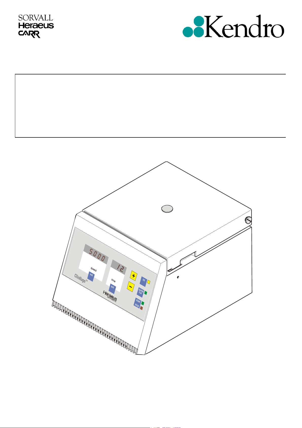
Clinifuge
Update Parts List Feb '02
120V 60 Hz
SERVICE MANUAL P/N 12003539
®

TABLE OF CONTENTS
Section Title Doc.- No. Page
1 OPERATING INSTRUCTIONS
(not part of this manual)
1.1 Brochure Clinifuge_E
2 SERVICE
2.1 Servicing Schedule " - " 2-1/2
2.2 Trouble Shooting " - " 2-3/4
2.3 Test Points " - " 2-5
2.4 Cleaning of Instrument Parts " - " 2-6
2.5 Electrical Safety Check " - " 2-6
3 FUNCTIONAL DESCRIPTION
3.1 Block Functions " - " 3-1
3.2 Functions of Main Board " - " 3-1
4DIAGRAMS
4.1 Block Diagram " - " 4-1
4.2 Wiring Diagrams " - " 4-2/3
4.3 Wiring Connection Diagrams " - " 4-4
4.4 Main Board 14 - Component Plan " - " 4-5
4.5 Main Board 14 - Wiring Diagram " - " 4-6/8
4.6 Main Board 178 - Component Plan " - " 4-9
4.7 Main Board 178 - Wiring Diagram " - " 4-10/12
5 DISASSEMBLY OF INSTRUMENT PARTS
5.1 Housing / Casing Parts " - " 5-1
5.2 Electrical Components " - " 5-2
5.3 Drive Components " - " 5-3
5.4 Mechanical Components " - " 5-3
5.5 Service Kit " - " 5-4
5.6 Dismantling and assembling the rotor " - " 5-4
Clinifuge_2
Clinifuge_3
Clinifuge_4
Clinifuge_5
6 SPARE PART FIGURES AND LISTS
6.1 Spare Part Figures " - " 6-1/2
6.2 Spare Part Lists " - "
7 TECHNICAL BULLETINS
8 Preventive Maintenance Checklist
Edition: 02 TABLE OF CONTENTS
24.01.02 AH Page: 0 - 2
Clinifuge_6
Clinifuge_7 7-1/6
Clinifuge
Quality Products – Lifetime Care
Benefits
■ Easy to Use
■ Able to run wide range of
most popular medical tubes
■ Maintenance free
■ Safe
Maintenance free
The Clinifuge is equipped with a brushless
motor, so there is no need to replace
carbon brushes. Beside saving time and
money, this also ensures clean operating
conditions.
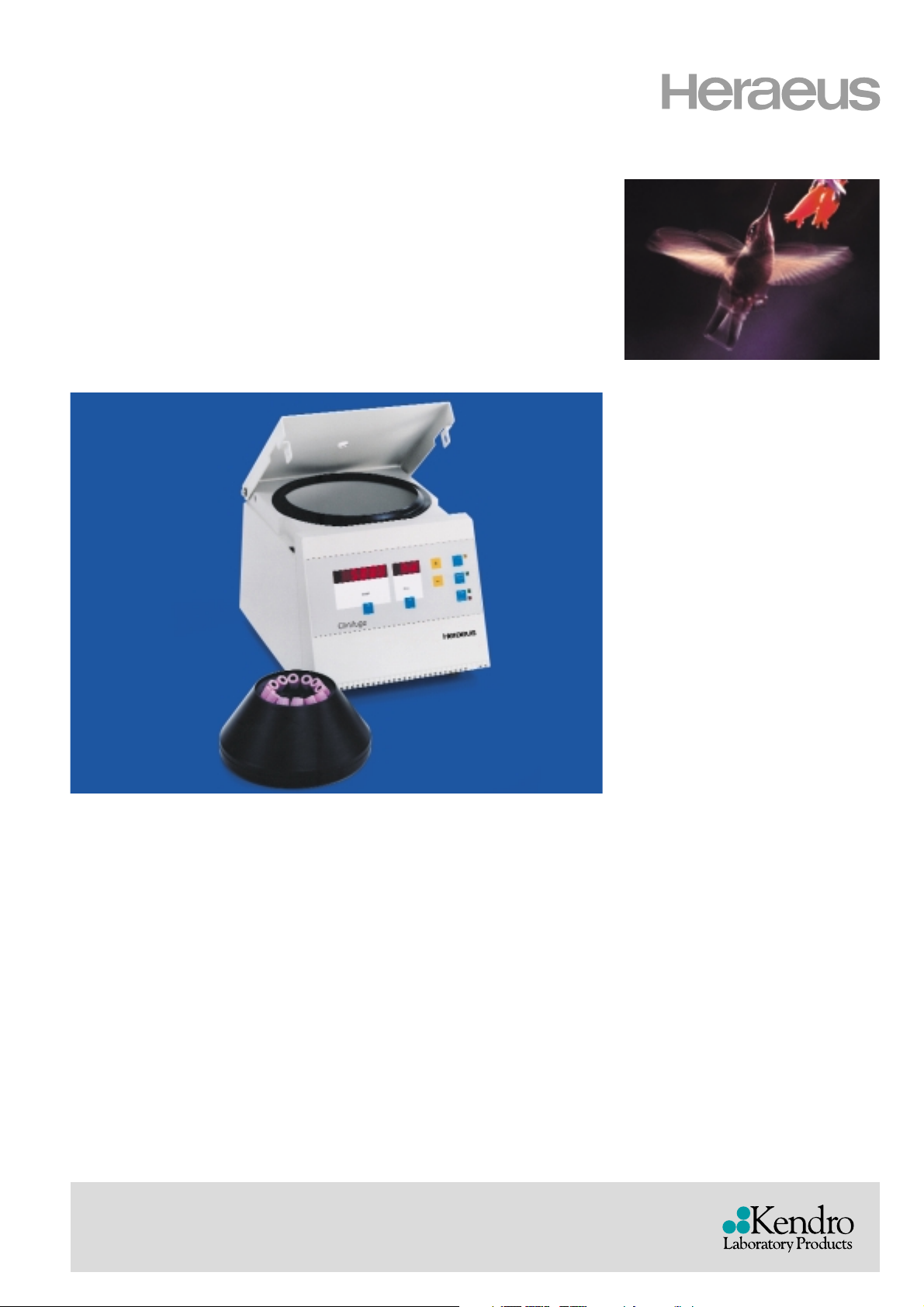
Accessories
The Clinifuge comes complete with an
adapter set and an autoclavable rotor.
Made of impact resistant, fiber glass
reinforced polyamide, this rotor offers
high stability and outstanding run
characteristics.
It is easily removed for cleaning in the
laboratory washing machine. An extensive
range of adapters permits centrifugation
of all standard 5, 7, 10 and 15 ml tubes,
including the popular “Monovette”, “Vacutainer” and “VenoJect” blood collection
tubes.
Safety
Samples processed in today’s laboratories
often harbor unknown risks. The Clinifuge
complies with international safety standards and is equipped with a lid lock, lid
interlock and steel armoured guard ring.
Clinifuge
▼
Functions
The microprocessor controlled Clinifuge is
equipped with bright digital displays and
touch-pad keys for quick and easy setting
of speed and run-time. The values last
used are stored. To repeat a run, simply
press the start key.
It is also designed with a user friendly self
diagnosis system which indicates faults
directly on the display.
The Heraeus®Clinifuge is functional and sophisticated with an ergonomic design.
It is ideal for use in medical practices, clinical and small laboratories and as a stand-by
unit in large laboratories.
Easy to Use
CLINIFUGE
®
COMPACT CENTRIFUGE
CLINIFUGE
®
COMPACT CENTRIFUGE
Asia Pacific Kendro Laboratory Products (H.K.) Limited · Hong Kong · Tel. +852 2711-3910 · Fax +852 2711-3858 · info@kendro.com
Europe, Middle East, Africa
Kendro Laboratory Products International Sales · Hanau · Germany · Tel. +49 (6181) 35-300 · Fax +49 (6181) 35 59 44 · info@kendro.de
Latin America Kendro Laboratory Products International Sales · Newtown · USA · Tel. 1 (203) 270-2080 · Fax. 1 (203) 270-2210 · info@kendro.com
USA Kendro Laboratory Products · Newtown · Tel. 1 (800) 522-7746 · Fax. 1 (203) 270-2166 · info@kendro.com
Internet http://www.kendro.com
Quality Products – Lifetime Care
Registered to ISO 9001. Kendro Laboratory Products meet or exceed stringent quality and product safety standards: CE for the European Union, and UL, cUL or
CSA standards for North America. ©2000 Kendro Laboratory Products. All Rights Reserved. S00254
Printed in Germany 5C 03/00 N 4t Künzel
TECHNICAL DATA
TECHNICAL DATA
ORDER NUMBERS
ORDER NUMBERS
Model Order No.
Clinifuge 120 V; 60 Hz 75003539
Accessories for Clinifuge
Angle rotor
1)
75003760
Max. speed (rpm) 5000
Max. RCF (x g) 2600
Max. capacity (ml) 12 x 15
Max. radius (cm) 9.65
Acceleration time (sec) 40
Braking time (sec) 45
Accessories for angle rotor 75003760
Tube volume Type of tube Dimension (mm) Tubes Type of Adapter
(ml) Diam. x Length per rotor adapter Order No.
7 Glass tubes (DIN) 12 100 12 yellow 75003227
1)
15 Glass tubes (DIN) 16 100 12
4)
–
3-5 VenoJect II (Terumo) 13 75 12 cream + 75003227
1)
rubber pad
7 VenoJect II (Terumo) 13 100 12 yellow 75003227
1)
9-10 VenoJect II (Terumo) 16 100 12 sleeves 75003763
3)
3-5 Vacutainer (BD)
2)
13 75 12 cream + 75003227
1)
rubber pad
7 Vacutainer (BD)
2)
13 100 12 yellow 75003227
1)
7 Vacutainer (BD) 16 75 12 sleeves + 75003763
3)
rubber pad 75003266
10 Vacutainer (BD)
2)
16 100 12
4)
–
15 Vacutainer (BD) 16 125 6
4)
–
4 Sarstedt Monovette 11.5 83.5 12 cream 75003227
1)
5 Sarstedt Monovette 13 90 12 cream 75003227
1)
7.5 Sarstedt Monovette 15 92 12
4)
–
9 Sarstedt Monovette 16.5 92 6 rubber pad 75003762
12 (Urine) Sarstedt Monovette 16.5 101.5 6
4)
–
Urine tubes BD, Terumo 16 100 12 sleeves 75003763
3)
1)
included with centrifuge
2)
tube incl. Hemoguard cap
3)
included with rotor
4)
not necessary
The adapter set 75003227 will contain the yellow and cream adapters andrubber pads.
Clinifuge 120 V version
Description Microprocessor controlled table top centrifuge
Maximum speed (rpm) 5000
Minimum speed (rpm) 1600
Maximum RCF (x g) 2600
Minimum RCF (x g) 270
Maximum capacity (ml) 12 x 15 (glass)
Controller Microprocessor controller for time and speed
Drive Brushless induction motor, microprocessor controlled
Runtime 1–99 min. and continuous operation (Hold)
Program memory Stores values last entered, unlimited
Safety Lid lock and lid interlock, steel armoured guard ring
Design Fibre glass reinforced polyamide housing with high noise and
vibration insulation properties
Dimensions (H xWxD) (mm/inch) 240 x 284 x 375 /9.5 x 11.2 x 14.8
Weight (incl. rotor) (kg / Ibs) Approx. 10.7 /23.5
Power consumption (W) 65
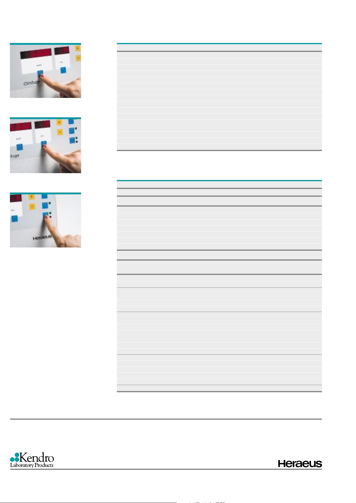
Set the required speed…
…and set the required time
With the “start” button, repeat
runs can easily be recalled
For Ordering or Technical Information

Service
2.1 Servicing Schedule (yearly procedure recommended)
2.1.1 Maintenance Routine without Dismantling the Centrifuge
2.1.1.1 Electrical Installation and Safety
• Switch OFF the centrifuge and disconnect the unit from power, check voltage supply and mains
fusing (16 Amps, slow blow characteristic)
• Check condition of plug and wall socket - (let) replace defective parts
• Check cord condition and fixing / connection - replace or refit it
2.1.1.2 Location and Mech anic a l In s tall ati on
• Check the base (ground, table, lorry with lockable wheels etc.) For resonance-free and stable
conditions
• Check for a well ventilated place and sufficient distances to walls or adjacent equipment, without
exposure to direct sunlight
• Check the leveling of instrument (use a spirit level)
2.1.1.3 Lid Locking Mec han is m an d Safety
• Connect the centrifuge to power and switch ON
• Check for easy lid closing and self-acting lid opening - if in disorder, readjust lid’s swivel hinge
and/or lock assembly
• Check the central rubber gasket for lid sealing and replace it, if damaged
• For checking the safety: start the centrifuge, let it shortly run and stop it, the lid must not be
unlocked by the microprocessor until the “end” message is shown on the display - if safety circuit is
out of function, replace the main board
2.1.1.4 Cleanliness of Spin Chamber and Motor Casing
• Open the lid and remove the rotor (for loosening turn the central winged nut anti clockwise from the
motor shaft)
• Clean the spin chamber with a dry and absorbent cloth (remove all dust and moisture - see also 2.5
Cleaning)
• Check the cleanliness of the motor casing and take care of the annular slot around the motor shaft:
penetrating fluids can damage the upper motor baring, remove fluids with an injector and/or
absorbent paper
2.1.1.5 Rotor and Accessories Condition and Sealing
• Check the condition of rotors and accessory parts (especially all supporting or stressed partitions):
the rotor and/or accessory parts must not be used any longer, if there are visible traces of
mechanical damage
2.1.1.6 Rotor Fixing and Motor Sha ft
• Check the trouble-free condition of the locking nut and replace it in case of malfunction
• High performance rotors made of plastic have a limited service life. Due to safety reasons they
have to be exchanged after 10,000 cycles or after being in use for five years. The expiry date can
be seen on the date clock in the rotor lower shell. The two-digit number in the middle represents
the year and the arrow points to the expiry month. The number of cycles may be checked at any
time by closing the lid and keeping both “set” keys pressed. The accumulated rotor cycles will be
displayed in the speed display.
• Check the condition of the drive motor shaft: the centrifuge must not be used any longer, if the
drive shaft is damaged (bend, thread is worn out, horizontal grooves etc.)
2.1.1.7 Temperature Level
• Check the air inlet underneath the lid and under the bottom plate for free ventilation, insufficient air
flow will lead to temperature rise of rotor, motor and electronic parts
Edition: 03 Servicing Schedule
17.04.02 AH Page: 2-1
Clinifuge

Service
2.1.2 Maintenance Routine after Dismantling the Centrifuge Casing
2.1.2.1 Motor Support ing E lements
• Check the supporting and damping elements of the drive motor and replace them in case of
increased rubber abrasion or abundance of imbalance but at least every 3 years
2.1.2.2 Braking Circuit
• Check the function of the braking circuit (even brake effect)
2.1.2.3 Lead and Screwing Connection
• Check the terminal and plug connections of all leads and on all boards and electrical components,
tighten all loosen screwing connections, refit or replace defective parts
• Check the screwing connections of all boards, mechanical and electrical components and re-
tighten them if necessary (use screw locking lac for motor mounts and lid lock assembly)
2.1.2.4 Protection Earth Core and Grounding Connections
• Check the protection earth core for continuity and all grounding plug connectors
• Check isolation resistance and accessible current (see 2.5)
Edition: 03 Servicing Schedule
17.04.02 AH Page: 2-2
Clinifuge

2.2 Trouble Shooting
Error
Indication
Displays
remain
dark
Displays
are
illuminated
, but drive
doesn’t
start
Drive
makes
noises-no
good
separation
result
Drive
doesn’t
decelerate
Lid cannot
be opened
by key
pressure
at
standstill
Error Cause
No mains
voltage supply
No low voltage
supply
Motor over-
temperature
switch has
tripped
Rotor didn’t
turn
Motor didn’t
start
Mechanics
Electrical
No brake
current
Lid coil is not
or not
sufficiently
supplied with
voltage
Faulty lid coil Faulty winding of coil Replace complete lid lock
Lid is not
correctly
locked
Service
Possible Error
Source
Mains fuse or circuit
breaker failed
Defective mains cord Check instrument cord, replace defective parts
Defective unit fuse or
fuses on main board
Faulty connection
from indication to
power board
Faulty indication or
power board
Motor temperature is
higher than 120°C
Rotor is jammed
Motor is jammed Replace motor
Connections inter
drive and main board
Defective drive
Faulty condenser Replace condenser
Faulty main board Remove main board completely and replace it
Wear out of motor
rubber mount
Motor bearing Change motor completely
Defective terminal
connection, faulty
lead or motor winding
Defective driving Replace main board
Faulty main board Remove main board completely and replace it
Missing mains voltage
PTC resistor has
released
Faulty driving or triac
circuit
Lid bolt is jamming Push lid into lock and press the key again
Lid is deformed or
disadjusted
Check fuse or circuit breaker, replace or switch
Replace it, if fuse blows again, disconnect
electrical parts, otherwise replace main board
Check connections on CPU, indicat. Board and
connecting leads, replace defective parts
Let motor cool down, then check temperature
Check for easy rotor movement, remove any
Check terminal and lead connections, replace
Check resistance of motor windings, replace
Check voltage on motor terminal and winding
resistances -see test points on boards
Remedy see above, manual opening only at
After a waiting time of 1-2 minutes press key
Corrective Procedure
on again
Replace main board
switch and leads with Ohmmeter
jamming objects
faulty parts
faulty parts
Replace motor rubber mounts
standstill
again
Replace the complete main board
Readjust the lid centrically
Edition: 03 Trouble Shooting
17.04.02 AH Page: 2-3
Clinifuge

Error
Indication
“LId“
message
appears in
speed
display
“OPEn“
message
in speed
display
“br “
message
appears in
speed
display
„E-“„ 2“
message
appears in
speed field
„E-“„ 3“
message
appears in
speed field
„E-“„12“
message
appears in
speed field
All dots in
the display
are
illuminated
Error Cause
Lid was
opened
manually
during run
Protection
circuit (15V)
for lid control
was
interrupted
during the run
15V supply
circuit is
interrupted at
standstill
Rotor comes
to standstill
without braking
force
Maintenance
counter
expired
No brake
current
Checksum
error of NV-
RAM
Disturbed data
transfer from
NV-RAM
Maintenance
counter
expired
Service
Trouble Shooting
Possible Error
Source
Forbidden
intervention
Emergency opening
can only be used at
standstill
Defective micro
switch or leads or
connectors to micro
switch are interrupted
Defective micro
switch or leads or
connectors to micro
switch are interrupted
Short interruption of
mains supply
Rotor has reached
10000 cycles
Faulty main board Remove main board completely and replace it
NV-RAM is not
initialized or false
Faulty main board Remove main board completely and replace it
Rotor has reached
10000 cycles
Close lid immediately, turn power off/on, wait
for termination of br phase until end message
Check leads and connectors to micro switch, in
case of a faulty micro switch, replace lid lock
Wait for rotor standstill (appr. 75 seconds) and
Replace rotor, NV-Ram and motor supports
Check NV-RAM and socket, insert the correct
Replace rotor, NV-Ram and motor supports
Corrective Procedure
appears
device completely
Check leads and micro switch
re-start
(Service Kit)
NV-RAM
(Service Kit)
Edition: 03 Trouble Shooting
17.04.02 AH Page: 2-4
Clinifuge

Service
2.3 Test Points
Test Points Unit value Conditions
Mains terminal XA
Lid micro switch
Plug XB
Terminal XC
Motor voltage
Motor current I
Motor windings
resistance 20°C
-insulation value
Lid solenoid
terminal XD
120V AV All given voltage and current values refer either to 120V (±10%)
160V DC Voltage drop by open lid at 120V units
Rotor #3760 not loaded, in each case measured after reaching the
selected speed
1600rpm
4000rpm
5300rpm
at the beginning of the braking phase
at the end of the braking phase
Rotor #3760 not loaded, in each case measured after reaching the
selected speed with a soft iron or digital effective measuring
instrument
1600rpm
4000rpm
5300rpm
maximum during acceleration
maximum during braking phase
switch OFF unit, pull off motor plug
mains winding (black – green)
auxiliary winding (black – yellow)
resistance inter each phase and motor casing
switch OFF unit,
resistance at 20°C (68°F)
M
approx.
58V AC
105V AC
120V AC
80V AC
75V AC
Approx.
1,2A
1,2A
0,8A
3,3A
2,0A
14,6Ω
14,6Ω
> 10MΩ
29Ω
Edition: 03 Test Points
17.04.02 AH Page: 2-5
Clinifuge
Service
2.4 Cleaning of Instrument Parts
ATTENTION - WARNING!
The electrical and electronic components must not be cleaned with moist detergents!
For Cleaning the centrifuge housing or its accessories see Operating Instructions section 1
(maintenance and care).
• Electronic components
Clean dusty components carefully with a dry and soft brush and remove loose dust with a vacuum
cleaner
• Vent holes
Remove dirt from vent holes of front panel or bottom plate using a brush and vacuum cleaner
2.5 Electrical Safety Check
ATTENTION!
A final electrical safety check must be performed after each maintenance and/or repair!
• Resistance check of protective conductor
The measuring value of the resistance between the mains plug's grounding pin and the grounding
conductors of the motor, electronic chassis and the casing must not exceed 200 mΩ.
• Insulation resistance Check
Check also the insulation resistance between the poles of the mains plug and the grounding
conductor; the resistance value must be more than 2 MΩ.
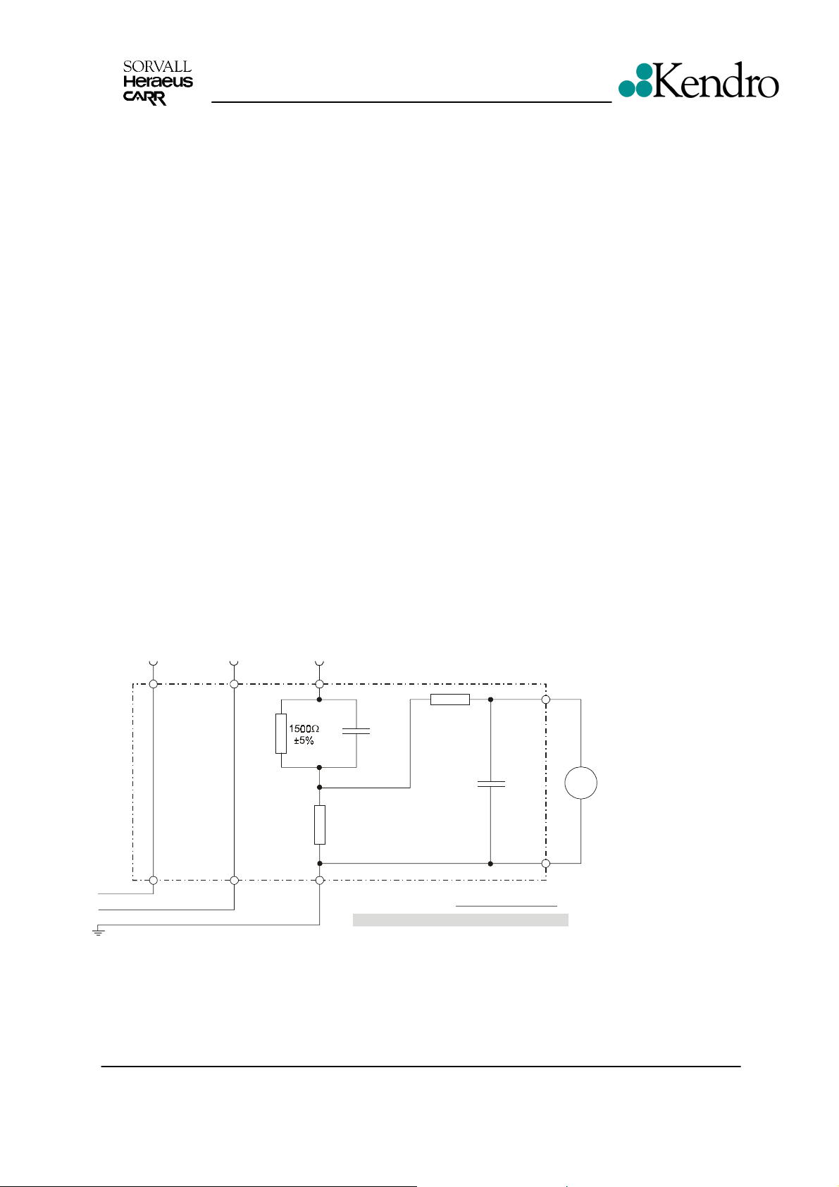
• Accessible current measured to EN 61 010
The accessible current must not exceed 3.5 mAmps in single fault condition (interrupted protection
earth wire)! In accordance with the EN61010, IEC1010 and UL3101 such a fault condition can be
reproduced by the following measuring circuit.
Steckergehäuse / plug-in casing
10k
Ω
±5%
0,022µF
±5%
I [mA] = U [mV] / 500:
max max
≡
L (N)
N (L)
PE
500
±1%
0,22µF
±5%
Ω
Körperstrom:
accessible current:
U = 1750mV I = 3,5mA
Edition: 03 Cleaning, Electrical Safety Check
17.04.02 AH Page: 2-6
Spezifaktionen für Meßgerät
- TRMS, DC - 5kHz oder mehr
- Eingangswiderstand > 1M
- Toleranz 5% oder besser
- Crest Faktor 5 oder besser
V
AC
Specifaction for the meter
- TRMS, DC - 5kHz or more
- Input resistance > 1M
- Tolerance 5% or better
- Crest Factor 5 or better
Clinifuge
Ω
Ω

FUNCTIONAL DESCRIPTION
3 Functional Description
3.1 Block Functions
The Clinifuge is a microprocessor controlled laboratory tabletop centrifuge with induction drive motor
and integrated air cooling system.
The unit incorporates following boards and components (see block diagram 4-1):
· Main board 14 or main board 178 with microprocessor part and power electronics
· Key and indication board (programming: MEGACONTROL simple), part of the main board
· 1 phase induction motor with phase shift capacitor and integrated thermal over temperature
switch (C. O. 125°C)
· Double lid lock assembly with solenoid and integrated micro switch (mechanical bolt keeper,
magnetically dislocking), attached in front on both sides of the vessel
3.2 Main Board Functions
The main board 14 / 178 is mounted completely behind the front panel. The components on main
board are arranged in following groups (see wiring diagram page 4-2).
· Board fusing (2 x 6.25 Amps. slow blow feature)
· Noise filter
· Power pack for low voltage supply of microprocessor part and power electronics (potential
separated by transformer)
· Triac control circuit for lid solenoid ( DC supply via bridge rectifier)
· Bridge rectifier for DC intermediate circuit supplying brake path and frequency converter
· Microprocessor part with CPU
· Exchangeable NV-RAM containing specific data of the unit
3.2.1 Power Pack
The power pack (transformer, bridge rectifier and voltage regulator) generates:
U1 = 5V: supplies central processor, key and indication board reference potential: protective
conductor (GND)
3.2.2 Intermediate Circuit with Brake Path and Frequency Converter
The DC intermediate circuit serves as an energy store between the AC power input and the
transmitted motor performance. The intermediate circuit consists of a bridge rectifier (4 diodes) and
two serial connected reservoir capacitors. The intermediate circuit is over voltage protected.
Edition: 02 Block Functions, Main Board Functions
17.01.02 AH Page: 3-1
Clinifuge
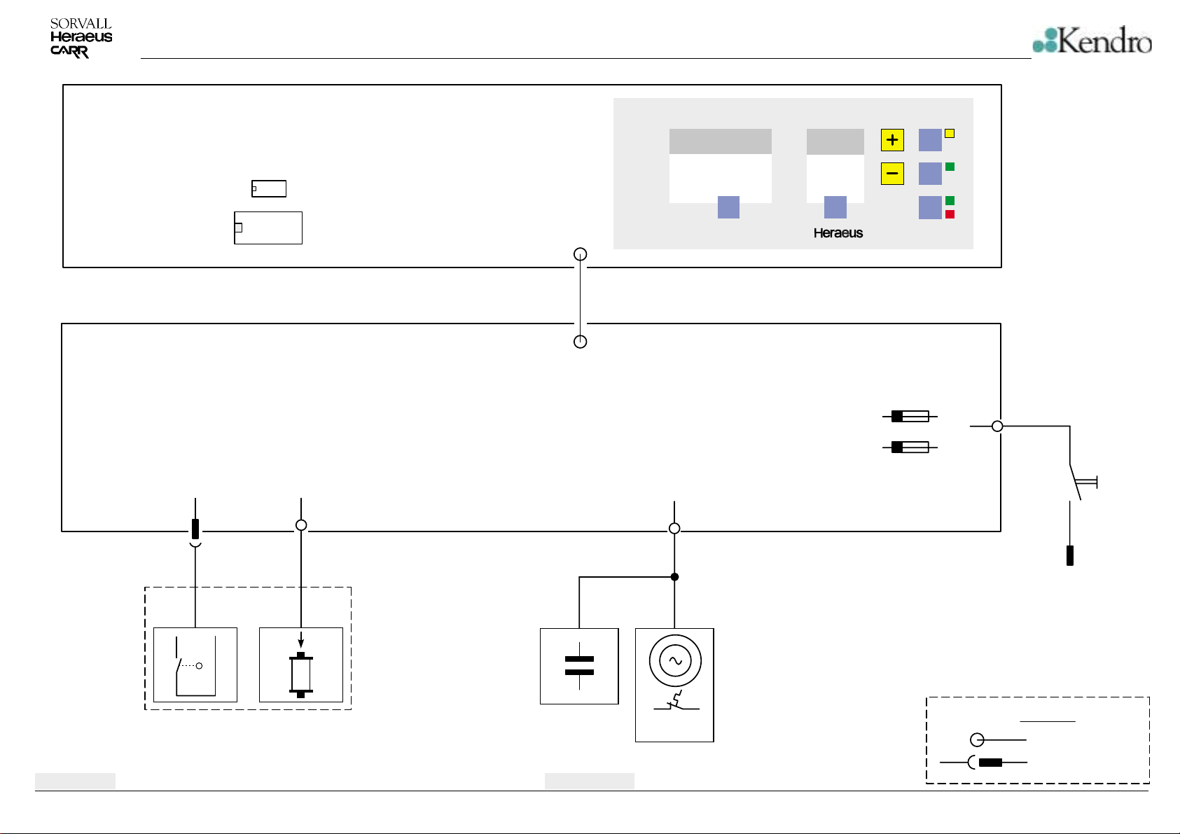
DIAGRAMMS
Main Board (Controller, )
Key and Indication Part
NV-RAM
µC
Main Board (Power Electronics)
XA
XD
XF
XF
Clinifuge
XC
speed
TM
set
time
set
F1
F2
lid
quick
run
start
stop
XA
S0
Edition: 02
23.01.02 AH
S1
S2
Lid Switch
Y1
Y2
Unlocking Solenoid
C1
Phase shift
capacitor
Block Diagram
4-1
120°C
M1
Motor
Mains
Mains Switch
Legend
solder connection
plug connection
Clinifuge
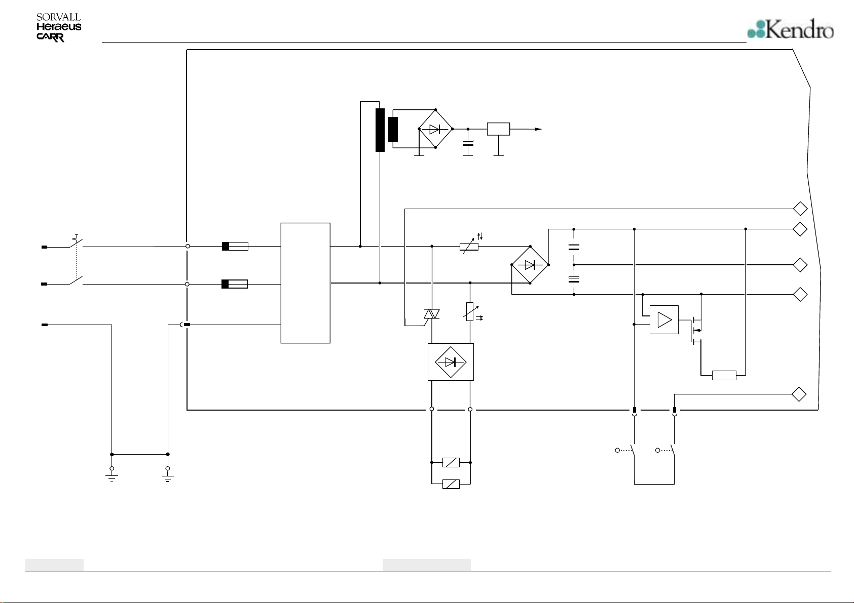
Main Board
DIAGRAMMS
Transformer, Rectifiers and Regulators
7805
A1=GND
5V (VCC)
Mains Switch
Mains
S0
PE
Chassis
PE
Motor
XL
XN
XPE
F1
F2
F1, F2
6,25 AT
Noise
Filter
NTC
PTC
XC/1 XC/2
Y1
Y2
J
J
DC intermediate circuit
XA/1
5
1
2
3
R4
XA/2
S2S1
Lid SwitchLid solenoid
Brake Resistor
4
Edition: 02
23.01.02 AH
Schematic Diagram
4-2
Clinifuge
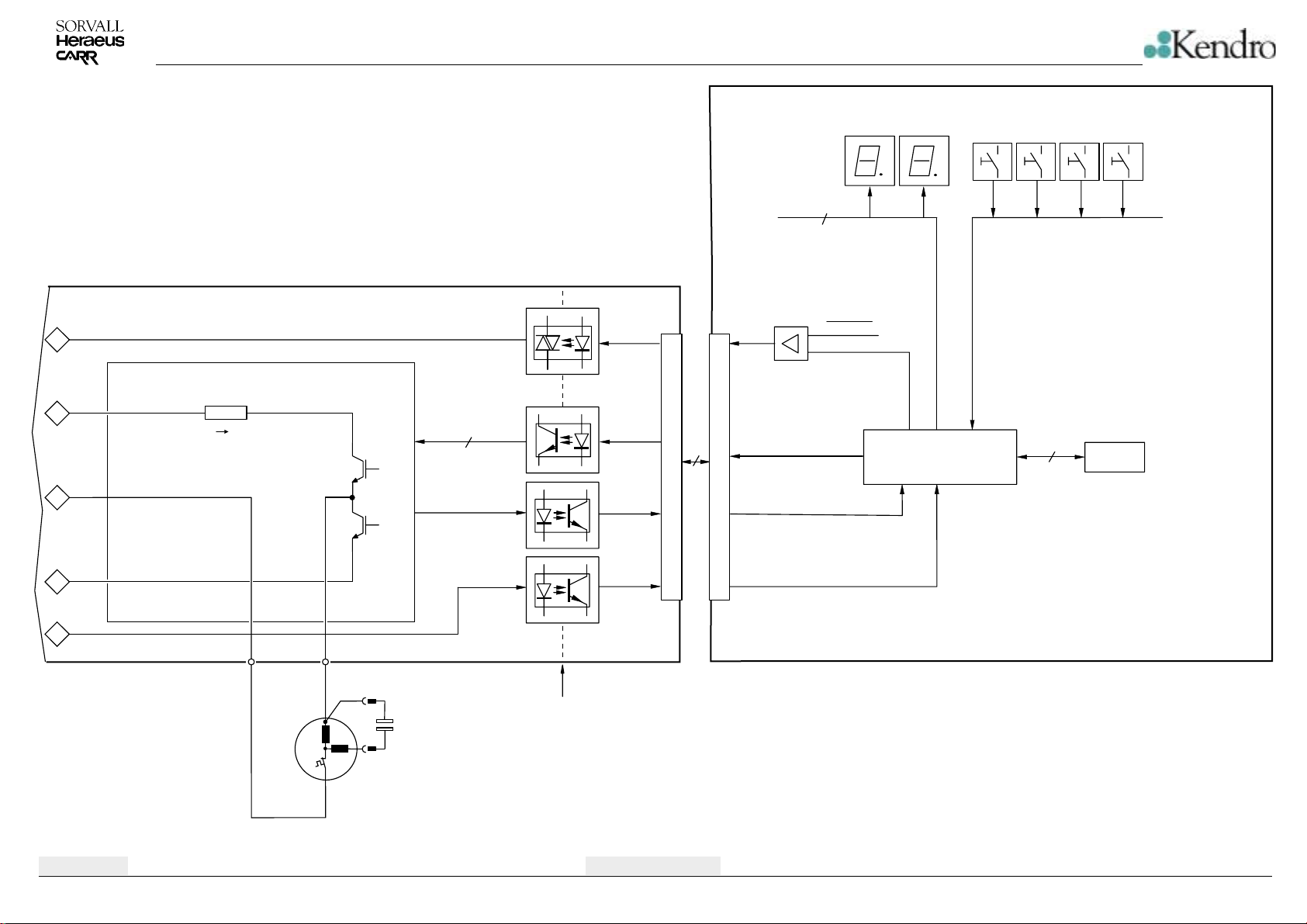
DIAGRAMMS
H1…H8 S1…S7
8
A,B,C,D
E,F,G,DP
Main Board Part 2
Y1/Y2
5
XG XG
Current Control Res.
RESET
µP - Part
1
2
3
4
Edition: 02
23.01.02 AH
i
dyn
XC/1 XC/2
Motor and run capacitor
125°C
C
L
C = 12µF
L
10
Physical Separation
HGTPs
14
i
dyn
“LId”...
Schematic Diagram
4-3
i
dyn
"LId"
CPU
4
NV-RAM
Key and indication part
Clinifuge
 Loading...