

Page 1

FastMig
SF 52W, SF 53W
Operating manual
Bruksanvisning
Gebrauchsanweisung
Manual de instrucciones
Käyttöohje
Manuel d’utilisation
Manuale d’uso
Gebruiksaanwijzing
Brugsanvisning
Instrukcja obsługi
Manual de utilização
EN
DA
DE
ES
FI
FR
IT
NL
NO
PL
PT
Инструкции по эксплуатации
Bruksanvisning
操作手册
RU
SV
ZH
Page 2

Page 3

OPERATING MANUAL
English
Page 4

EN
CONTENTS
1. Preface ........................................................................................................... 3
1.1 General ....................................................................................................................................... 3
2. Use .................................................................................................................. 4
2.1 Connecting and mounting the panel ............................................................................. 4
2.2 Functions of SF 52W and SF 53W function panel ...................................................... 5
2.3 SF 52W and SF 53W operations ........................................................................................ 6
2.4 Additional welding functions ..........................................................................................10
2.5 FastMig welding programs ...............................................................................................11
2.6 Panel SF 52W and SF 53W setup parameters ............................................................14
3. FastMig error codes ..................................................................................17
4. Disposal ....................................................................................................... 18
5. Ordering numbers .................................................................................... 18
2
FastMig SF 52W, SF 53W
Page 5

1. PREFACE
1.1 General
Congratulations on choosing the SF panel. Used correctly, Kemppi products can signicantly
increase the productivity of your welding, and provide years of economical service.
This operating manual contains important information on the use, maintenance and safety of
your Kemppi product. The technical specications of the equipment can be found at the end
of the manual.
Please read the manual carefully before using the equipment for the rst time. For your
own safety and that of your working environment, pay particular attention to the safety
instructions in the manual.
For more information on Kemppi products, contact Kemppi Oy, consult an authorised Kemppi
dealer, or visit the Kemppi web site at www.kemppi.com.
The specications presented in this manual are subject to change without prior notice.
Important notes
Items in the manual that require particular attention in order to minimise damage and
personal harm are indicated with the ’NOTE!’ notation. Read these sections carefully and follow
their instructions.
Disclaimer
While every eort has been made to ensure that the information contained in this guide
is accurate and complete, no liability can be accepted for any errors or omissions. Kemppi
reserves the right to change the specication of the product described at any time without
prior notice. Do not copy, record, reproduce or transmit the contents of this guide without
prior permission from Kemppi.
EN
© Kemppi Oy / 1515
3
Page 6

EN
2. USE
FastMig SF 52W and SF 53W control panels are designed to be used only with synergic power
sources FastMig KMS 300, 400, or 500. SF 52W panel can be mounted to MXF 63 (200 mm wire
spool) wire feeder and SF 53W panel to MXF 65 and 67 (300 mm wire spool) wire feeders.
2.1 Connecting and mounting the panel
Fasten the ribbon cable connector from the MXF wire feed unit to the function panel.
MXF 65
1.
1. Place the bottom edge of the panel behind the securing clips on the machine. Remove
the xing pin from the top edge with, for example, a screwdriver. Then gently push
the upper part of the panel into place. Make sure that the cables do not get damaged,
continue gently pushing the upper part of the panel until it clips into place.
2. Finally secure the panel into place with the additional black plastic security clip provided
(MXF 65 only). Ensure that the clip is positioned correctly. You will notice that the clip
does not seat snuggly if it's positioned upside down.
MXF 63 + MXF 67
+
MXF 63 MXF 67
2.
4
FastMig SF 52W, SF 53W
Page 7
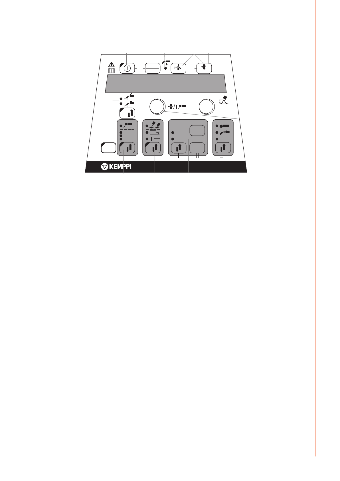
2.2 Functions of SF 52W and SF 53W function panel
7.
6.
WIRE INCH
8.
V
U
15.
13.
SET
SAVE
PANEL
CH
ch remote
W004270
SF 53W
16.14.
10.
9.
SELECT
SYNERGIC
PROGRAM
1.
2.
4T
2T
SETUP
MMA
WISE
1-MIG
MIG
MMA
11.
quick
setup
/ MINILOG
3. 4.
ARC FORCE
DYNAMICS
PEN
12.
5.
GAS TEST
m/min
mm
A
POWER
MEMORY
SET
ON
weld
data
ch clear
1. ON/OFF button
2. a) Wire feed speed/welding current/sheet thickness display
b) Selected SETUP entry display
3. MIG dynamics/MMA Arc Force/Wise Forming Pulse selection **)
4. Display of air/liquid cooled MIG gun (selection from setup)
5. Gas test
6. Weld data: Show last used welding parameters in displays
7. Wire inch
8. a) Welding voltage display
b) Selection display for adjustable parameters
9. a) 1-MIG/WISE synergic welding program check **)
b) 1-MIG/WISE synergic welding program selection (long press) **)
10. a) Selection of switching logic: 2T/4T/4T Minilog *)
b) Long press: Setting the basic parameters (SETUP)
11. Selection of welding process MIG, 1-MIG, MMA, WISE **)
12. Selection of additional MIG functions/WisePenetration **) (long press)
13. a) Adjustment of wire feed speed
b) Adjustment of welding power setting 1-MIG/WiseRoot/WiseThin **
c) Adjustment of MMA current
d) Selection of SETUP parameter
e) Selection of 1-MIG/WiseRoot/WiseThin welding program (material group) **
14. Memory channels, storage of MIG parameters
15. a) Welding voltage adjustment
b) Adjustment of length of welding arc (1-MIG)
c) Adjustment of MIG dynamics
d) Adjustment of SETUP parameter
e) Selection of 1-MIG/WiseRoot/WiseThin welding program (program number) **
f) WiseRoot and WiseThin base current adjustment **
16. Manual control/remote control unit selection
*) Minilog is not included in standard delivery.
**) Wise products are available as optional welding process solutions. Not included in the
standard delivery. Please visit www.kemppi.com or Kemppi Datastore.
EN
© Kemppi Oy / 1515
5
Page 8

EN
2.3 SF 52W and SF 53W operations
ON/OFF button (1)
The wire feed unit remains in the OFF position when the power source is switched on, thus
preventing start-up. ’OFF’ is shown on the display.
When the ON/OFF button is pressed for more than 1 second, the unit starts up. The unit is now
ready for welding and will automatically return back to it previous position, before the power
was cut o. The wire feed unit starts up also by pressing three (short) times the switch of the
welding gun.
Basic settings and displays
With MIG welding the wire feed speed is set via left potentiometer (control knob) and the
value is shown on the left display. The welding voltage is set via right potentiometer (control
knob) and the value is shown on the right display. During welding, the left display shows the
actual welding current value and the display on the right shows the welding voltage.
With electrode welding (MMA) the welding current value is set via the potentiometer and
the value is shown on the left display. The display on the right shows the idling voltage of the
power source. During welding the left display shows the actual welding current value and the
display on the right shows the welding voltage.
When MIG dynamics/electrode welding Arc force adjustment is activated with Arc Force/
Dynamics button the value is adjusted via right potentiometer (control knob) (see the
information on adjustment of MIG dynamics/arc force).
With Synergic 1-MIG welding, the power value is set via left potentiometer (control knob) and
the length of the arc via right potentiometer (control knob) (see ’1-MIG welding’).
Adjustment of MIG dynamics/Arc Force (3)
With MIG welding dynamics adjustment is inuenced on welding stability and spatter
amount. Zero setting is recommended basic setting. Values –> min (-1 ... -9), softer arc for
reduced spatter amount. Values –> max (1 ... 9), harder arc for increased stability and when
100 % CO₂ shielding gas is used when welding steel.
With electrode welding Arc Force adjustment is inuenced on welding stability. Adjustment
is needed for using dierent types of electrodes. Control range (-9 ... 0) is commonly used
for welding electrodes for stainless steel. Control range (0 ... +9) is used for harder arc
characteristic to increase stability, e.g. for welding with thicker basic electrodes and using
lower current value than recommendated. Factory set value (0) is a good general use for
adjusting the roughness of the arc.
Indication of liquid-cooled MIG gun (4)
You can activate either liquid- or air-cooled MIG gun with a setup parameter. For more
information, see chapter 2.6.
If the LED (4) is lit, liquid-cooling is activated in the system. In this case, ensure that you have
connected a liquid-cooled MIG gun to the equipment. The cooling units starts on the next
machine startup.
6
FastMig SF 52W, SF 53W
Page 9

Gas test (5)
WIRE INCH
GAS TEST
SET
ON
CH
PANEL
SAVE
SET
MEMORY
quick
setup
weld
data
ARC FORCE
DYNAMICS
4T
2T
SETUP
PEN
POWER
U
A
V
m/min
mm
/ MINILOG
The gas test button opens the gas valve without activating the wire feed or power source. Gas
ows for 20 seconds by default. The display shows the remaining gas ow time. The default
time of gas ow can be adjusted via the right-hand potentiometer within a range of 0 to 60
seconds. The new time setting is recorded in the memory. The gas ow can be discontinued
by pressing the ON/OFF button or the start switch of the gun.
Weld data (6)
The weld data function is activated by pressing buttons 5 and 7 simultaneously. The weld
data function returns the welding current and voltage values to the displays that were in use
during the last weld.
Wire inch (7)
The wire inch button starts the wire feed motor without opening the gas valve and without
engaging the power source. The default wire feed speed is 5 m/min. The speed can be
adjusted via the right-hand potentiometer. When the button is released, the wire feed stops.
Operation returns to normal approx. 3 seconds after release of the button or if the ON/OFF
button is pressed briey.
Selection of welding process (11)
MMA
WISE
1-MIG
MIG
MMA
The welding process – normal MIG, 1-MIG or Wise – can be chosen by the welding process
selection button. In normal MIG welding wire feed speed and welding voltage is adjusted
separately. In synergic 1-MIG and Wise welding the welding voltage and other parametres
related to welding are optimally bound to each other! In synergic welding the setting for
power and arc lenght are adjusted.
Wise welding is the facility provided separately, so the function is not in every equipment.
Electrode welding (MMA) is selected by pressing the button for >1 second.
NOTE! When electrode welding is selected, the power source, the electrode holder connected to it
and the MIG gun become energised (open circuit voltage).
EN
© Kemppi Oy / 1515
7
Page 10

Selection of MIG operating procedure (10)
WIRE INCH
GAS TEST
quick
setup
weld
data
ARC FORCE
DYNAMICS
4T
2T
POWER
U
A
V
m/min
mm
/ MINILOG
/ MINILOG
4T
2T
SETUP
MIG 2T: MIG welding with two-sequence procedure of welding gun start switch
1. switch pressed: welding starts
2. switch released: welding stops
MIG 4T: MIG welding with four-sequence procedure of welding gun start switch
1. switch pressed: shielding gas ow starts
2. switch released: welding starts
3. switch pressed: welding stops
4. switch released: shielding gas ow stops
Minilog: When Minilog is selected, 4T/Minilog LED ashes. Minilog is an additional function,
which can be purchased separately. (Minilog is also referred as 'Matchlog' in DataStore.)
Without Minilog license, press of the button chooses between 2T and 4T.
EN
Setup (10)
SETUP
When the adjustment of SETUP parameters has been conrmed with a long press of the
SETUP button (10), the adjustable parameter is selected via left potentiometer (control knob)
and the name of the parameter is shown on the left display. The parameter’s value is set via
right potentiometer (control knob) and the value is shown on the display on the right (see
’SETUP functions’).
Synergic 1-MIG or Wise welding (9, 11)
SELECT
SYNERGIC
PROGRAM
In Synergic 1-MIG welding, the optimal welding parameters for the welding wires and gas
used are recorded in the unit. The welding is controlled by adjusting the welding power and
arc length.
Synergic Wise processes are additional functions, which can be purchased separately.
Welding program selection:
Before starting to weld, a welding program suitable for the welding wire and gas used must
be chosen based on this Operating Manual.
Welding program selection is activated by pressing Synergic Program button longer than one
second. In this case both displays begin to ash and the material group is selected from the
left-hand potentiometer and the welding program for the material group in question from the
right potentiometer; see the enclosed table.
The selected programme is immediately recorded in the memory. To get back to normal status
press ON/OFF (1) key, or Synergic PROGRAM button (9).
8
Use of a selected welding program:
Select the relevant welding process with the 1-MIG selection button (11). Check that the
welding program corresponds to the welding wire and shield gas in use. The check is
performed by briey pressing the Synergic PROGRAM button (9), after which the displays
show the material group and the welding program number. Consult the above-mentioned
table for the wire type and gas that correspond with the welding program.
Set the desired welding power via the left-hand potentiometer (control knob) and the arc
length via the potentiometer (control knob) on the right.
FastMig SF 52W, SF 53W
Page 11

Memory functions (15)
WIRE INCH
GAS TEST
PANEL
weld
data
POWER
U
A
V
m/min
mm
U
V
MEMORY
SET
ON
SET
SAVE
CH
Storage of settings
The memory functions can be used to record useful welding values in the memory. There are
ten dierent memory locations: 0 … 9.
In addition to welding values (wire feed speed, welding voltage), function options such as
2T/4T, Creep Start, and Crater Level are recorded in the memory.
Storage in memory is performed as follows:
1. Press the MEMORY button twice; the SET light begins to ash if the channel is not in use.
If the channel is in use, the light remains lit. If the memory is empty, press the MEMORY
key once to get in SET mode.
2. Select the desired memory channel with the CH key.
3. Make the settings and store them in the memory by pressing the SAVE button.
4. Press the MEMORY key twice. Notice that the ON light is lit.
5. Begin welding.
If you wish to change some values, the light must be switched from the ON setting to the SET
setting to enable you to select the required parameters. Press the SAVE button to complete
the procedure. It is also possible to save the parameters of the current weld by pressing SET
when the memory function is in OFF status (all lights o ). The channel can be cleared by
pressing MEMORY and the CH button simultaneously in SET mode.
EN
Use of stored settings
1. Press the MEMORY button.
2. Select the memory channel via the CH button.
3. Begin welding.
Remote Selection Button (17)
PANEL
Short Press: Panel /Gun Remote / Hand remote selection. If remote auto recognition is
selected ON, only those remote controls which can be found are selected.
Long Press: CH remote function ON/OFF. Gun remote or Hand remote control must be rst
selected before CH remote function can be selected ON/OFF. When active, memory channels
are selectable from the remote control device.
The Ch remote function enables selection of memory channels via the selection controller
located on the gun. The function is activated by pressing REMOTE and CH buttons
simultaneously. When the CH-remote is activated the light in remote control or in gun control
starts to ash.
© Kemppi Oy / 1515
9
Page 12

EN
WIRE INCH
GAS TEST
SET
ON
CH
PANEL
SAVE
SET
MEMORY
quick
setup
weld
data
ARC FORCE
DYNAMICS
4T
2T
SETUP
PEN
POWER
U
A
V
m/min
mm
/ MINILOG
2.4 Additional welding functions
Activation with the MIG function selection button (11)
MMA
WISE
1-MIG
MIG
MMA
The selection button for additional MIG functions can be used to activate the Hot Start, Crater
Fill or WisePenetration (licence required) function. Further presses of the selection button can
select one or more of the above func tions. Only the available additional functions for each
method can be selected.
• HotStart function is meant to reduce initial welding errors when welding highly heatconductive materials such as aluminium. Hot Start can be selected when using Synergic
1-MIG welding and when the 4T operating mode is selected. In this case, when the start
switch of the gun is held down, a xed pre-gas time is displayed after which welding
starts at the level determined by the SETUP mode’s Hot Start parameter, returning to the
normal level when the gun switch is released.
• WisePenetration™ is a welding function for delivering constant welding power
regardless of changes in the stick out length. It is an optional feature, which can be
purchased through Kemppi DataStore.
• Crater Fill is meant to reduce welding defects caused by end cratering. The Crater Fill
function can be selected when using Synergic 1-MIG welding and when the 4T operating
mode is selected. When the gun switch is pressed down in connection with termination
of welding, the welding power drops to the crater-lling level selected previously. The
crater lling function is discontinued by releasing the gun switch.
NOTE! In crater ll, the initial value of the welding power must be greater than the nal
value, and therefore the adjustment ranges for the initial and nal values are restricted
automatically, if necessary.
Welding Level
Crater Fill Start Level
Crater Fill Time
Crater Fill End Level
Parameters related to these functions are set via the SETUP function (see ’SETUP functions’).
Stopping is performed as with the normal 4T function.
The values of parameters related to additional MIG functions can be changed either with the
SETUP function (see ’SETUP’) or with the Quick SETUP function. Quick SETUP is activated by
simultaneously pressing buttons 1 and 3. In this way, parameters related to MIG additional
functions can be set.
Parameters are selected for adjustment via potentiometer on the left. The value of the
parameter is set via potentiometer on the right. The value is immediately recorded in the
memory.
10
FastMig SF 52W, SF 53W
Page 13

Activation through SETUP
Other additional MIG functions are activated through SETUP.
• Creep Start is meant to facilitate the initial weld – e.g., when welding with a high wire
feed speed. The wire feed speed is kept low until the wire touches the work piece and
the current begins to ow. Creep Start can be selected with normal MIG welding or with
Synergic 1-MIG welding.
• WiseFusion™ is a welding function for ensuring consistent weld quality in all positions.
It is an optional feature, which can be purchased through Kemppi DataStore.
• MatchLog™ contains MiniLog™ function for quickly changing welding parameters on
the run. It is an optional feature, which can be purchased through Kemppi DataStore.
• If your welding needs change and you wish to update your system in the future, you can
order additional welding programs or other welding software and load them to your
system with Kemppi DataGun eld programming device.
For further information about the available welding programs, modied processes and special
enhanced arc performance solutions, visit Kemppi web site at www.kemppi.com or contact
the local Kemppi dealer.
2.5 FastMig welding programs
1-MIG (Standard welding programs)
Fe group Wire (mm) Material Shielding gas
101
102
103
104
106
111
112
113
114
116
121
122
123
124
126
152
154
164
174
184
194
0.8 Fe Ar+18%-25%CO₂
0.9 Fe Ar+18%-25%CO₂
1.0 Fe Ar+18%-25%CO₂
1.2 Fe Ar+18%-25%CO₂
1.6 Fe Ar+18%-25%CO₂
0.8 Fe CO₂
0.9 Fe CO₂
1.0 Fe CO₂
1.2 Fe CO₂
1.6 Fe CO₂
0.8 Fe Ar+8%CO₂
0.9 Fe Ar+8%CO₂
1.0 Fe Ar+8%CO₂
1.2 Fe Ar+8%CO₂
1.6 Fe Ar+8%CO₂
0.9 Fe Metal Ar+18%-25%CO₂
1.2 Fe Metal Ar+18%-25%CO₂
1.2 Fe Metal CO₂
1.2 Fe Rutil Ar+18%-25%CO₂
1.2 Fe Rutil CO₂
1.2 Fe Basic Ar+18%-25%CO₂
EN
© Kemppi Oy / 1515
11
Page 14

EN
Ss group Wire (mm) Material Shielding gas
201
202
203
204
206
211
212
213
214
216
221
222
223
224
231
232
233
234
242
244
252
254
0.8 CrNiMo 19 12 Ar+2%CO₂
0.9 CrNiMo 19 12 Ar+2%CO₂
1.0 CrNiMo 19 12 Ar+2%CO₂
1.2 CrNiMo 19 12 Ar+2%CO₂
1.6 CrNiMo 19 12 Ar+2%CO₂
0.8 CrNiMo 19 12 Ar+30%He+1%O₂
0.9 CrNiMo 19 12 Ar+30%He+1%O₂
1.0 CrNiMo 19 12 Ar+30%He+1%O₂
1.2 CrNiMo 19 12 Ar+30%He+1%O₂
1.6 CrNiMo 19 12 Ar+30%He+1%O₂
0.8 CrNi 23 12 Ar+2%CO₂
0.9 CrNi 23 12 Ar+2%CO₂
1.0 CrNi 23 12 Ar+2%CO₂
1.2 CrNi 23 12 Ar+2%CO₂
0.8 CrNi 23 12 Ar+30%He+1%O₂
0.9 CrNi 23 12 Ar+30%He+1%O₂
1.0 CrNi 23 12 Ar+30%He+1%O₂
1.2 CrNi 23 12 Ar+30%He+1%O₂
0.9 FC-CrNiMo 19 12 Ar+18%-25%CO₂
1.2 FC-CrNiMo 19 12 Ar+18%-25%CO₂
0.9 FC-CrNiMo 19 12 CO₂
1.2 FC-CrNi 23 12 Ar+18%-25%CO₂
Al group Wire (mm) Material Shielding gas
303
304
306
313
314
316
1.0 AlMg5 Ar
1.2 AlMg5 Ar
1.6 AlMg5 Ar
1.0 AlSi5 Ar
1.2 AlSi5 Ar
1.6 AlSi5 Ar
SPE group Wire (mm) Material Shielding gas
401
402
403
404
411
412
413
421
423
424
0.8 CuSi3 Ar
0.9 CuSi3 Ar
1.0 CuSi3 Ar
1.2 CuSi3 Ar
0.8 CuSi3 Ar+2% CO₂
0.9 CuSi3 Ar+2% CO₂
1.0 CuSi3 Ar+2% CO₂
0.8 CuAl8 Ar
1.0 CuAl8 Ar
1.2 CuAl8 Ar
12
FastMig SF 52W, SF 53W
Page 15

WiseRoot (Standard welding programs)
Fe group Wire (mm) Material Shielding gas
802
803
804
812
813
814
0.9 Fe Ar+18%-25%CO₂
1.0 Fe Ar+18%-25%CO₂
1.2 Fe Ar+18%-25%CO₂
0.9 Fe CO₂
1.0 Fe CO₂
1.2 Fe CO₂
Ss group Wire (mm) Material Shielding gas Backing gas
822
823
824
832
833
834
0.9 CrNiMo 19 12 Ar+2%CO₂ Ar
1.0 CrNiMo 19 12 Ar+2%CO₂ Ar
1.2 CrNiMo 19 12 Ar+2%CO₂ Ar
0.9 CrNiMo 19 12 Ar+30%He+1%O₂ Ar
1.0 CrNiMo 19 12 Ar+30%He+1%O₂ Ar
1.2 CrNiMo 19 12 Ar+30%He+1%O₂ Ar
WiseThin (Standard welding programs)
Fe group Wire (mm) Material Shielding gas Backing gas
701
702
703
704
711
712
713
714
0.8 Fe Ar+18%-25%CO₂
0.9 Fe Ar+18%-25%CO₂
1.0 Fe Ar+18%-25%CO₂
1.2 Fe Ar+18%-25%CO₂
0.8 Fe CO₂
0.9 Fe CO₂
1.0 Fe CO₂
1.2 Fe CO₂
Ss group Wire (mm) Material Shielding gas Backing gas
721
722
723
724
0.8 CrNiMo 19 12 Ar+2%CO₂ Ar
0.9 CrNiMo 19 12 Ar+2%CO₂ Ar
1.0 CrNiMo 19 12 Ar+2%CO₂ Ar
1.2 CrNiMo 19 12 Ar+2%CO₂ Ar
Cu group Wire (mm) Material Shielding gas Backing gas
743
753
NOTE! More welding programs are available in Kemppi DataStore.
1.0 CuSi3 Ar
1.0 CuAl8 Ar
EN
© Kemppi Oy / 1515
13
Page 16

2.6 Panel SF 52W and SF 53W setup parameters
Normal MIG welding Setup -parameters
EN
Name of parameter
Pre Gas Time
Post Gas Time
Creep Start
Creep Start Level
Start Power
Post Current Time
Arc Voltage
Cable Length
Synergic MIG -welding SETUP -parameters
Name of parameter
Pre Gas Time
Post Gas Time
Creep Start
Creep Start Level
Hot Start Level
Hot Start 2T Time
Crater Fill End Level
Crater Fill Start Level
Crater Fill Time
Wise Fusion On
Wise Fusion Percent
Penetration Level
MiniLog On
MiniLog Level
Name on
display
PrG 0.0 – 9.9 s 0,0 s Pre gas time in seconds
PoG 0.0 – 9.9 s Aut Post gas time in seconds or automatically
Cr OFF, on OFF Switch creep start on or o.
CrE 10 – 170% 50% Percentage of wire feed speed:
StA -9 ... +9 0 Strength of start pulse
PoC -9 ... +9 0 Post current
Ard OFF, on OFF on: Display shows arc voltage
CAb std, 5 – 80m std Cable loss is calculated for optimal arc
Name on
display
PrG 0.0 – 9.9 s Syn Pre gas time in seconds or automatically
PoG 0.0 – 9.9 s Syn Post gas time in seconds or automatically
Cr OFF, on OFF Switch creep start on or o.
CrE 10 – 170% 50% Percentage of wire feed speed:
Hot -50 ... 75% 30% Percentage of welding power:
H2t 0.0 – 9.9 s 1.2 s The duration of the hot start in seconds in
CrL 10 – 250% 30% The welding power at the end of the crater
CrS 10 – 250% 30% The welding power at the beginning of
CrT 0.0 – 9.9 s 2.0 s The duration of the crater ll stage in
FUS OFF, on OFF
FUP 10...60% 25%
PEn -30 ... +30% 0%
ML on, OFF OFF
MLo -99 ... +200% 50%
Parameter
values
Parameter
values
Factory
setting
Factory
setting
Description
according to welding current (Aut)
10% slowed start
100% = no creep start function
170% accelerated start
OFF: Display shows pole voltage
control and for the Arc Voltage display
Description
according to synergic welding program
(Syn)
according to synergic welding program
(Syn)
10% slowed start
100% = no creep start function
170% accelerated start
-50% cold and +75% hot
2T mode
ll stage as a percentage of the welding
power preset value
the crater ll stage as a percentage of the
welding power preset value
seconds (only in 2T mode)
Switch Wise Fusion on/o (only in 1-MIG)
Percentage of Wise Fusion (only in 1-MIG)
Set the arc length where penetration
control begins (only in 1-MIG)
Switch on/o MiniLog
Set the minilog power level as a
percentage of the welding power
14
FastMig SF 52W, SF 53W
Page 17

Synergic Start Time
Synergic Start
FSt -9 ... +9 0 Start time in WiseRoot/WiseThin welding
FuL -30 ... +30 0 Voltage level in the beginning of
Voltage
Start Power
Post Current Time
Synergic MIG Unit
Arc Voltage
Cable Length
Common Setup -parameters for MIG processes
Name of parameter
Device Address
Using features of PMT
StA -9 ... +9 0 Strength of start pulse
PoC -9 ... +9 0 Post current
Unl m/min, mm, A m/min In 1-MIG and WiseRoot welding, the
Ard OFF, on OFF on: Display shows arc voltage
CAb std, 5 – 80m std Cable loss is calculated for optimal arc
Name on
display
Add 3 or 6 3 Wire feeder bus address
Gun OFF, on on on = PMT gun
Parameter
values
Gun
Gas Guard Connected
LongSystem Mode
Code Entry
PIN Code Entry
Panel Locking
Water Cooler
Wire Inch Stop
Auto Wire Inch
Demo Licence Time
GG no, YES no Implementation of gas guard
LSY OFF, on OFF on: Gives optimum welding characteristics
Cod ---, Ent --- Entering license codes manually:
PIn ---, PIn --- Enters pin code for Panel Locking
LoC OFF, on OFF Enables panel locking
Coo OFF, on on Enables water cooler
Inc OFF, on on OFF = Stops wire inch in case arc does not
AIn OFF, on on SuperSnake Automatic Wire Inch
dEt 3-h, 2-h, **’,
**’’, OFF
Factory
setting
WiseRoot/WiseThin welding
(not in WiseRoot/WiseThin)
parameter shown in left-hand display:
wire feed speed (m/min), sheet thickness
(mm) or average current (A)
OFF: Display shows pole voltage
(not in WiseRoot/WiseThin)
control and for the Arc Voltage display
(not in WiseRoot/WiseThin)
EN
Description
OFF = other gun
with long welding cables. Recommended
to be used when the cable length exceeds
40 m.
1. Adjust right potentiometer to (‘Ent’).
2. Press REMOTE.
3. Set code with right potentiometer.
4. Choose next with left potentiometer.
5. Go back to point 3, until all codes have
been set.
6. Approve by pressing REMOTE. (‘Suc cEs’)
ignite
on = Feeds wire as long as the welding
gun start switch is pressed.
function. Wire Inch button runs the ller
wire from the wire feeder up to the
SuperSnake.
The remaining time for the WiseDemo
licence
(readable value only).
3-h = max. 3 hours left
2-h = max. 2 hours left
**’ = ** minutes left
**’’ = ** seconds left
OFF = Demo period has expired.
© Kemppi Oy / 1515
15
Page 18

Restore Factory
FAC OFF, PAn, ALL OFF Control panel reset function.
Settings
Setup-parameters for MMA welding
OFF = No reset
PAn = Settings will be restored, but
memory channels remain unchanged
ALL = All settings will be restored to
factory values.
EN
Name of parameter
Start Power
Device Address
Code Entry
Restore Factory
Settings
NOTE! In these setup lists following functions needs activation (Err 171):
• Arc Voltage Display
• Minilog
• Panel Locking
• WisePenetration
• WiseFusion
Name on
display
StA -9 ... +9 0 Strength of start pulse
Add 3 or 6 3 Wire feeder bus address
Cod ---, Ent ---
FAC OFF, PAn, ALL OFF
Parameter
values
Factory
setting
Description
Entering license codes manually:
1. Adjust right potentiometer to (‘Ent’).
2. Press REMOTE.
3. Set code with right potentiometer.
4. Choose next with left potentiometer.
5. Go back to point 3, until all codes have
been set.
6. Approve by pressing REMOTE. (‘Suc cEs’)
Control panel reset function.
OFF = No reset
PAn = Settings will be restored, but
memory channels remain unchanged
ALL = All settings will be restored to
factory values
16
FastMig SF 52W, SF 53W
Page 19

3. FASTMIG ERROR CODES
The existence of possible faults in the equipment is investigated in connection with each
wire feed unit start-up. If a fault is detected, the fault in question will be indicated as an ’Err’
message on the panel display.
Error code examples:
Err 2: Undervoltage
The device has stopped because it has detected a mains undervoltage that disturbs welding.
Check the quality of the supply network.
Err 3: Overvoltage
The device has stopped because dangerously high temporary voltage surges or a continuous
over-voltage has been detected in the electric network. Check the quality of the supply
network.
Err 4: Power source is overheated
The power source has overheated. The cause may be one of the following:
• The power source has been used for a long time at maximum power.
• The circulation of cooling air to the power source is blocked.
• The cooling system has experienced a failure.
Remove any obstacle to air circulation, and wait until the power source fan has cooled down
the machine.
Err 5: Water unit alarm
The water circulation is blocked. The cause may be one of the following:
• Congestion or disconnection in the cooling pipeline
• Insucient cooling liquid
• Excessive cooling liquid temperature
Check the circulation of the cooling liquid and the air circulation of the water unit.
Err 54: No data communication from power source
The data transmission between the power source and the wire feed unit has been cut o or is
defective. Check the extension lead and connections.
Err 55: Power source is busy
The communication channel is busy. The power source is being used by another wire feed unit
or the programming for some other device in the channel (e.g. control panel) is in progress.
Err 61: The water unit is not found
Water unit is not connected to the equipment or there is a connection fault.
Connect up the water unit or change the setting of the unit to air-cooled, if you are using an
air-cooled welding gun.
Err 153: Overheating of liquid-cooled PMT gun
When starting to weld or during welding, the overheat protection on the liquid-cooled MIG
welding gun has activated. Check that there is sucient liquid in the cooling unit and that
air is circulating freely through it. Ensure that liquid is circulating freely through the cooling
hoses.
Err 154: Overloading of the wire feed motor
The welding has been interrupted because the loading of the wire feed motor has risen to
a high level. The cause of this could be a blockage of the wire line. Check the wire conduit,
contact tip and feed rolls.
Err 155: Warning of the wire feed unit overloading
The wire feed motor load level has risen. The cause could be dirty wire conduits or a gun cable
twisted into sharp curves. Check the state of the gun and clean the wire line if necessary.
Err 165: Gas guard alarm
Gas guard function has worked, because the pressure of gas has decreased. Possible reasons:
Gas is unconnected to the wire feeder. Gas has been ran out, gas hose is leaking or there is no
pressure enough in the gas web. Connect the gas to the wire feeder, check gas hose and the
pressure of the gas web.
EN
© Kemppi Oy / 1515
17
Page 20

EN
Err 171: Conguration not found for the device
The optional features cannot be used. There is no licence code for that or the equipment’s
internal data transmission has been cut o. Turn o the machine, detach the welding gun
and re-start the machine. If an error code does not appear in the display, the fault lies in the
welding gun. If this error code pertains, contact maintenance.
Err 172: A wrong conguration code has been supplied
License activation with DataGun has failed. Turn o the machine, detach DataGun and restart
the machine. Reconnect DataGun. If this error code recurs, contact maintenance.
Err 201: Use of PMT gun is prevented
You try to use the PMT welding gun, but the necessary settings have not been entered into
the machine’s control panel. Select ‘PMT gun’ from the control panel SETUP menu, if you wish
to use it. This fault can also occur with other guns, if the trigger contacts are bad or dirty.
Err 221: Two wire feeders connected with the same device address.
Two wire feed units have the same device address. Dene dierent addresses for the devices
as follows:
1. Press any button on either control panel (except the ESC button). “Add” (Device Address)
is displayed.
2. Change the device address using the right-hand control knob.
3. Return to normal status by pressing again any button on the control panel.
The machines will return to normal status within 15 seconds.
Other error codes:
The machine can show codes not listed here. In the event of an unlisted code appearing,
contact an authorised Kemppi service agent and report the error code shown.
4. DISPOSAL
Do not dispose of electrical equipment with normal waste!
In observance of European Directive 2002/96/EC on waste electrical and electronic
equipment, and its implementation in accordance with national law, electrical equipment
that has reached the end of its life must be collected separately and taken to an appropriate
environmentally responsible recycling facility.
The owner of the equipment is obliged to deliver a decommissioned unit to a regional
collection centre, per the instructions of local authorities or a Kemppi representative. By
applying this European Directive you will improve the environment and human health.
5. ORDERING NUMBERS
SF 52W MSF 53, MXF 63 6085200W
SF 53W MSF 55, MSF 57, MXF 65, MXF 67 6085300W
18
FastMig SF 52W, SF 53W
Page 21

Page 22

KEMPPI OY
Kempinkatu 1
PL 13
FIN-15801 LAHTI
FINLAND
Tel +358 3 899 11
Telefax +358 3 899 428
export@kemppi.com
www.kemppi.com
Kotimaan myynti:
Tel +358 3 899 11
Telefax +358 3 734 8398
myynti.@kemppi.com
KEMPPI SVERIGE AB
Box 717
S-194 27 UPPLANDS VÄSBY
SVERIGE
Tel +46 8 590 783 00
Telefax +46 8 590 823 94
sales.se@kemppi.com
KEMPPI NORGE A/S
Postboks 2151, Postterminalen
N-3103 TØNSBERG
NORGE
Tel +47 33 346000
Telefax +47 33 346010
sales.no@kemppi.com
KEMPPI DANMARK A/S
Literbuen 11
DK-2740 SKOVLUNDE
DANMARK
Tel +45 4494 1677
Telefax +45 4494 1536
sales.dk@kemppi.com
KEMPPI BENELUX B.V.
NL-4801 EA BREDA
NEDERLAND
Tel +31 765717750
Telefax +31 765716345
sales.nl@kemppi.com
KEMPPI (UK) LTD
Martti Kemppi Building
Fraser Road
Priory Business Park
BEDFORD, MK44 3WH
UNITED KINGDOM
Tel +44 (0)845 6444201
Telefax +44 (0)845 6444202
sales.uk@kemppi.com
KEMPPI FRANCE S.A.S.
65 Avenue de la Couronne des Prés
78681 EPONE CEDEX
FRANCE
Tel +33 1 30 90 04 40
Telefax +33 1 30 90 04 45
sales.fr@kemppi.com
KEMPPI GMBH
Perchstetten 10
D-35428 LANGGÖNS
DEUTSCHLAND
Tel +49 6 403 7792 0
Telefax +49 6 403 779 79 74
sales.de@kemppi.com
KEMPPI SPÓŁKA Z O.O.
Ul. Borzymowska 32
03-565 WARSZAWA
POLAND
Tel +48 22 7816162
Telefax +48 22 7816505
info.pl@kemppi.com
KEMPPI AUSTRALIA PTY LTD
13 Cullen Place
P.O. Box 5256, Greystanes NSW 2145
SMITHFIELD NSW 2164
AUSTRALIA
Tel. +61 2 9605 9500
Telefax +61 2 9605 5999
info.au@kemppi.com
OOO KEMPPI
Polkovaya str. 1, Building 6
127018 MOSCOW
RUSSIA
Tel +7 495 240 84 03
Telefax +7 495 240 84 07
info.ru@kemppi.com
ООО КЕМППИ
ул. Полковая 1, строение 6
127018 Москва
Tel +7 495 240 84 03
Telefax +7 495 240 84 07
info.ru@kemppi.com
KEMPPI, TRADING (BEIJING) COMPANY LTD
Unit 105, 1/F, Building #1,
No. 26 Xihuan South Rd.,
Beijing Economic-Technological Development
Area (BDA),
100176 BEIJING
CHINA
Tel +86-10-6787 6064
+86-10-6787 1282
Telefax +86-10-6787 5259
sales.cn@kemppi.com
肯倍贸易(北京)有限公司
中国北京经济技术开发区
西环南路26号
1号楼1层105室(100176)
电话:+86-10-6787 6064/1282
传真:+86-10-6787 5259
sales.cn@kemppi.com
KEMPPI INDIA PVT LTD
LAKSHMI TOWERS
New No. 2/770,
First Main Road,
Kazura Garden,
Neelankarai,
CHENNAI - 600 041
TAMIL NADU
Tel +91-44-4567 1200
Telefax +91-44-4567 1234
sales.india@kemppi.com
KEMPPI WELDING SOLUTIONS SDN BHD
No 12A, Jalan TP5A,
Taman Perindustrian UEP,
47600 Subang Jaya,
SELANGOR, MALAYSIA
Tel +60 3 80207035
Telefax +60 3 80207835
sales.malaysia@kemppi.com
1923430
1515
www.kemppi.com
 Loading...