

Page 1
FastMig
MF 29
Operating manual
Bruksanvisning
Gebrauchsanweisung
Manual de instrucciones
Käyttöohje
Manuel d’utilisation
Manuale d’uso
Gebruiksaanwijzing
Brugsanvisning
Instrukcja obsługi
Manual de utilização
EN
DA
DE
ES
FI
FR
IT
NL
NO
PL
PT
Инструкции по эксплуатации
Bruksanvisning
RU
SV
Page 2

Page 3

OPERATING MANUAL
English
EN
© Kemppi Oy / 1515
Page 4

EN
CONTENTS
1. Preface ...........................................................................................3
1.1 General ....................................................................................................................................... 3
2. Product introduction ..................................................................... 4
2.1 Operation control and connectors .................................................................................. 4
2.2 Connection of system ........................................................................................................... 5
2.3 DuraTorque™ 400, 4 wheel wire feed mechanism ..................................................... 6
3. Installation ..................................................................................... 8
3.1 Assembly of MIG system ...................................................................................................... 8
3.2 Mounting of MIG welding gun .......................................................................................... 8
3.3 Mounting and locking of wire spool ............................................................................... 8
3.4 Automatic wire feed to gun................................................................................................ 9
3.5 Adjustment of pressure ........................................................................................................ 9
3.6 Adjustment of tightness of spool brake ........................................................................ 9
3.7 Burn back time ........................................................................................................................ 9
3.8 Ground cable ............................................................................................................................ 9
3.9 Shielding gas ..........................................................................................................................10
3.9.1 Installing gas cylinder....................................................................................................10
3.10 Main switch I/O .....................................................................................................................11
3.11 Operation of cooling unit, FastCool 10 ........................................................................11
3.12 Hanging....................................................................................................................................11
4. Service, operation disturbances .................................................. 11
5. Maintenance ................................................................................ 12
5.1 Daily maintenance ...............................................................................................................12
5.2 Service shop maintenance ...............................................................................................12
5.2.1 disposal of the machine ................................................................................................12
6. Ordering numbers ....................................................................... 13
7. Technical data .............................................................................. 14
2
FastMig MF 29
Page 5

1. PREFACE
1.1 General
Congratulations on choosing the FastMig equipment. Used correctly, Kemppi products can
signicantly increase the productivity of your welding, and provide years of
economical service.
This operating manual contains important information on the use, maintenance and safety of
your Kemppi product. The technical specications of the equipment can be found at the end
of the manual.
Please read the manual carefully before using the equipment for the rst time. For your
own safety and that of your working environment, pay particular attention to the safety
instructions in the manual.
For more information on Kemppi products, contact Kemppi Oy, consult an authorised Kemppi
dealer, or visit the Kemppi web site at www.kemppi.com.
The specications presented in this manual are subject to change without prior notice.
Important notes
Items in the manual that require particular attention in order to minimise damage and
personal harm are indicated with the ’NOTE!’ notation. Read these sections carefully and follow
their instructions.
Disclaimer
While every eort has been made to ensure that the information contained in this guide
is accurate and complete, no liability can be accepted for any errors or omissions. Kemppi
reserves the right to change the specication of the product described at any time without
prior notice. Do not copy, record, reproduce or transmit the contents of this guide without
prior permission from Kemppi.
EN
© Kemppi Oy / 1515
3
Page 6
2. PRODUCT INTRODUCTION
FastMig MF is basic wire feeder designed for demanding enviroment. It can be used with
Kemppi's basic FastMig power sources KM 300, KM 400, and KM 500.
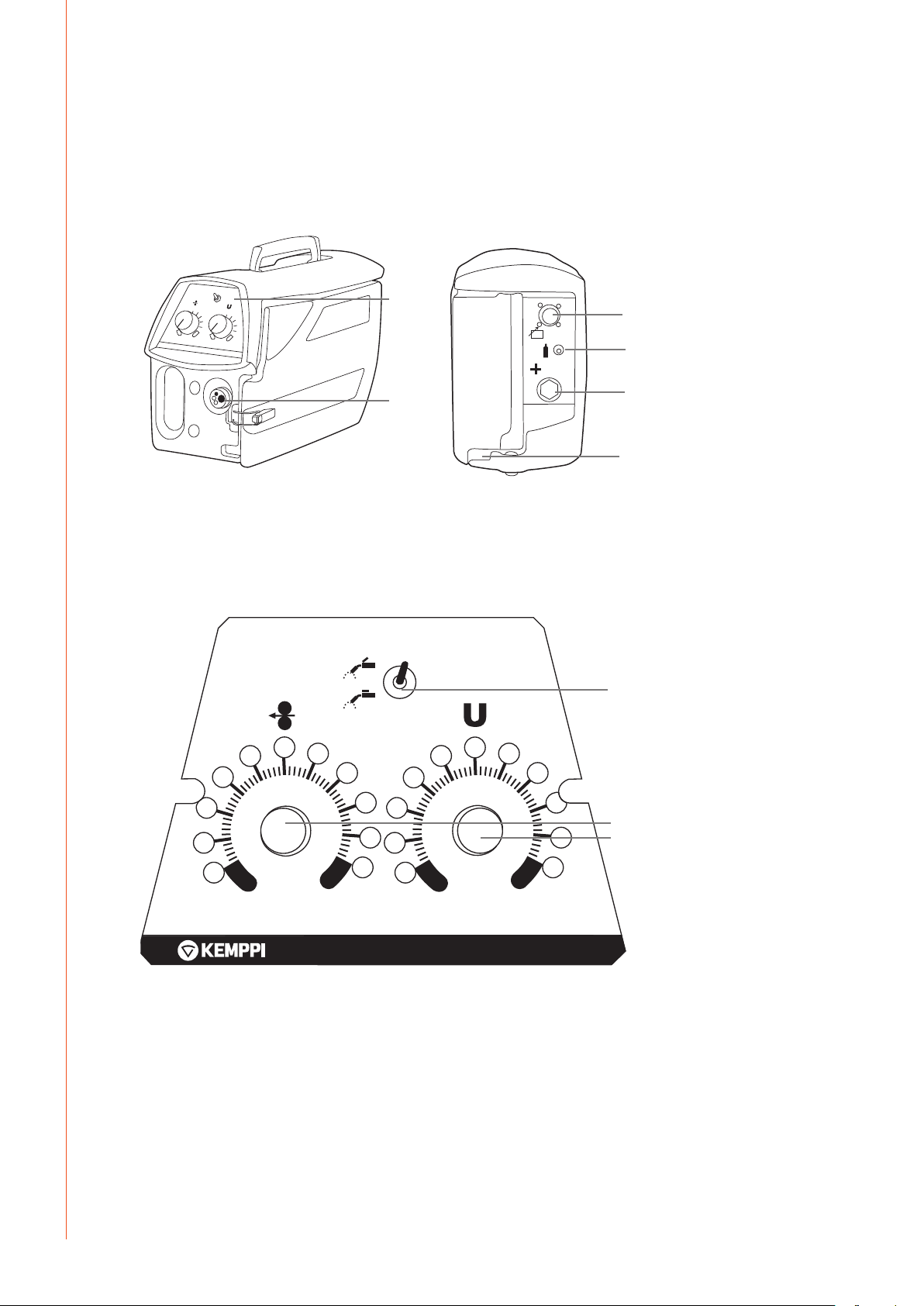
2.1 Operation control and connectors
EN
1. Control panel
2. Welding gun EURO connector
5
4
3
2
1
0
6
7
10
1.
3.
4.
2.
5.
6.
3. Connection for control cable
4. Shielding gas connection
5. Welding current cable connector
6. Lead-in of cooling liquid hoses
4T
1.
2T
5
4
3
8
2
6
7
8
2.
9
1
0
9
10
3.
4
1. Selection of gun operating mode
2. Adjustment of wire feed speed
3. Adjustment of welding voltage
FastMig MF 29
MIN
MAX MAXMIN
MF
MF
W001320
Page 7

2.2 Connection of system
EN
© Kemppi Oy / 1515
5
Page 8

EN
2.3 DuraTorque™ 400, 4 wheel wire feed mechanism
Wire guide tubes
ø mm outlet tube middle tube inlet tube
Ss, Al,
(Fe, Mc, Fc)
plastic
Fe, Mc, Fc
metal
0.6 W007437 W007429 W007293
0.8 – 0.9 W007438 W007430 W007294
1.0 W007439 W007431 W007295
1.2 W007440 W007432 W007296
1.4 W007441 W007433 W007297
1.6 W007442 W007434 W007298
2.0 W007443 W007435 W007299
2.4 W007444 W007436 W007300
0.8 – 0.9 W007454 W007465 W007536
1.0 W007455 W007466 W007537
1.2 W007456 W007467 W007538
1.4 – 1.6 W007458 W007469 W007539
2.0 W007459 W007470 W007540
2.4 W007460 W007471 W007541
6
FastMig MF 29
Page 9
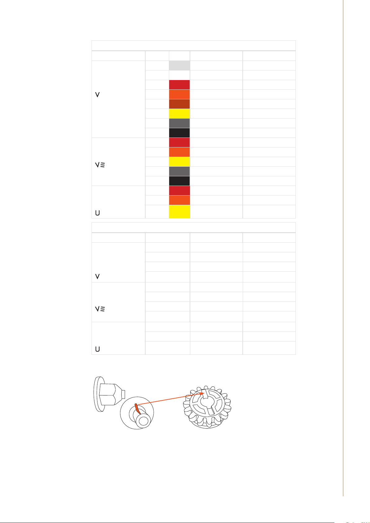
Wire feed rolls, plastic
Fe, Ss,
(Al, Mc, Fc)
V-groove
Fc, Mc, (Fe)
V-groove, knurled
Al, (Fc, Mc, Ss, Fe)
U-groove
ø mm lower upper
0.6 W001045 W001046
0.8 – 0.9 W001047 W001048
1.0 W000675 W000676
1.2 W000960 W000961
1.4 W001049 W001050
1.6 W001051 W001052
2.0 W001053 W001054
2.4 W001055 W001056
1.0 W001057 W001058
1.2 W001059 W001060
1.4 – 1.6 W001061 W001062
2.0 W001063 W001064
2.4 W001065 W001066
1.0 W001067 W001068
1.2 W001069 W001070
1.6 W001071 W001072
EN
Wire feed rolls, metal
ø mm lower upper
Fe, Ss,
(Al, Mc, Fc)
V-groove
Fc, Mc, (Fe)
V-groove, knurled
Al, (Fc, Mc, Ss, Fe)
U-groove
NOTE! Mount the lower feed roll, ensuring that the pin on the shaft ts in the cut on the feed roll.
0.8 – 0.9 W006074 W006075
1.0 W006076 W006077
1.2 W004754 W004753
1.4 W006078 W006079
1.0 W006080 W006081
1.2 W006082 W006083
1.4 – 1.6 W006084 W006085
2.0 W006086 W006087
1.0 W006088 W006089
1.2 W006090 W006091
1.6 W006092 W006093
© Kemppi Oy / 1515
7
Page 10

EN
3. INSTALLATION
3.1 Assembly of MIG system
Assemble the units in order mentioned below and follow mounting and operation
instructions which are delivered in packages.
Installation of power source
Read paragraph: ”Installation” in operation instructions for FastMig power sources and carry
out the installation according to that.
Mounting of KM power sources to transport wagon
Read and follow the instructions given in the transport cart installation/assembly manual
Connecting cables
Connect the cables in accordance with the equipment notes provided.
The polarity of the welding wire (+ or -) can be changed by replacing the MF welding current
cable and return current cable with the FastMig™ power source welding cable connector.
Mounting of FastMig wire feed units to boom
NOTE! Wire feed unit must be mounted to boom in such a way that its chassis is galvanic separated
both from swing arm and boom.
Suspension angle of wire feed unit can be changed by moving xing point in handle.
3.2 Mounting of MIG welding gun
In order to ensure trouble-free welding check in operation instructions of gun used by you
that wire guide tube and contact tip of gun are according to manufacturer’s recommendation
suitable to be used for wire feed diameter and type in question. To tight a wire guide tube
might cause for wire feed unit a bigger stress than normally as well as disturbances in wire
feed.
Screw snap connector of gun tight that there won’t come any voltage losses on connecting
surface. A loose connection will heat gun and wire feed unit and feeder.
3.3 Mounting and locking of wire spool
A
B
• Release the locking nut (A)!
• Mount the spool at its place. Note rotating direction of spool
• Lock the spool with locking nut.
NOTE! Check that in ller wire spool there are no parts sticking out, which could e.g. chafe against
chassis or door of wire feed unit. Dragging parts might expose chassis of wire feed unit under
voltage.
8
FastMig MF 29
Page 11

3.4 Automatic wire feed to gun
Automatic wire feed makes change of wire spool more rapid. In spool change the pressure of
feed rolls need not to be released and ller wire goes automatically to correct wire line.
• Make sure that groove of feed roll matches the diameter of welding wire used.
• Release the wire end from spool and cut o the bent length. Be careful that the wire
does not spill from the spool to sides!
• Straighten about 20 cm of the wire and see that the end of it has no sharp edges (le
o if necessary). A sharp edge may damage the wire guide tube and contact tip of the
welding gun.
• Draw a bit of loose wire from wire spool. Feed wire through back liner to feed rolls. Do
not release pressure of feed rolls!
• Press the gun switch and feed wire until wire goes through feed rolls to gun. See that
wire is in grooves of both feed roll pairs!
• Press still the gun switch until wire has come through contact tip.
Automatic feed may sometimes fail with thin wires (Fe, Fc, Ss: 0,6 – 0,8 mm, Al: 0,8 – 1,0 mm).
In that case you might have to open feed rolls and feed wire manually through feed rolls.
3.5 Adjustment of pressure
Adjust the pressure of feed rolls with the control screw (20) so that the wire is fed into the wire
guide tube evenly and allows a little braking when coming out from the contact tip without
slipping at the feed rolls.
NOTE! Excessive pressure causes attening of the ller wire and damage to the coating. It also
causes undue wear of the feed rolls as well as friction.
EN
3.6 Adjustment of tightness of spool brake
A
B
Brake force is adjusted by screwing the adjusting nut (B), tightening clockwise direction.
Adjust brake force as so big that the wire is not allowed to become too loose on the spool so
that it would spill from the spool when the rotation of the spool stops. Need for brake force is
increased with increase of wire feed speed.
Since the brake loads for its part the motor, you shouldn’t keep it unnecessarily tight.
3.7 Burn back time
Electronics of feed unit controls stopping of welding automatically so that the wire end
doesn’t melt fastened to the contact tip or the work piece. Automatics work regardless of the
wire feed speed. Can be adjusted also from power source SETUP-menu ('PoC').
3.8 Ground cable
Connecting of earth cable should be preferably connected directly to the welding material.
Contact surface of press always should be as large as possible.
Clean the fastening surface from paint and rust!
Use in your MIG equipment at least 70 mm². Thinner cross-sectional areas might cause
overheating of connectors and insulations.
Make sure that the welding gun in your use is designed for max. welding current needed by
you!
NOTE! Never use a damaged welding gun!
© Kemppi Oy / 1515
9
Page 12

3.9 Shielding gas
NOTE! Handle gas cylinder with care. There is a risk for injury if the cylinder or its valve is damaged!
For welding stainless steels, mixed gases are normally used. Check that the gas cylinder valve
is suitable for the gas. The ow rate is set according to the welding power used in the job. A
suitable ow rate is normally 8 – 10 l/min. If the gas ow is not suitable, the welded joint will
be sporous. Contact your local Kemppi-dealer for choosing gas and equipment.
3.9.1 Installing gas cylinder
NOTE! Always fasten gas cylinder properly in vertical position in a special holder on the wall or on a
carriage. Remember to close gas cylinder valve after having nished welding.
Parts of gas ow regulator
EN
A
A. Gas cylinder valve
B. Press regulation screw
C. Connecting nut
D. Hose spindle
E. Jacket nut
F. Gas cylinder pressure meter
G. Gas hose pressure meter
The following installing instructions are valid for most of the gas ow regulator types:
1. Step aside and open the cylinder valve (A) for a while to blow out possible impurities
from the cylinder valve.
2. Turn the press regulation screw (B) of the regulator until no spring pressure can be felt.
3. Close needle valve, if there is one in the regulator.
4. Install the regulator on cylinder valve and tighten connecting nut (C) with a wrench.
5. Install hose spindle (D) and jacket nut (E) into gas hose and tighten with hose clamp.
6. Connect the hose with the regulator and the other end with the wire feed unit. Tighten
the jacket nut.
7. Open cylinder valve slowly. Gas cylinder pressure meter (F) shows the cylinder pressure.
Note! Do not use the whole contents of the cylinder. The cylinder should be lled when
the cylinder pressure is 2 bar.
8. Open needle valve if there is one in the regulator.
9. Turn regulation screw (B) until hose pressure meter (G) shows the required ow (or
pressure). When regulating ow amount, the power source should be in switched on and
the gun switch pressed simultaneously.
Close cylinder valve after having nished welding. If the machine will be out of use for a long
time, unscrew the pressure regulation screw.
F
C
G
B
E
D
10
FastMig MF 29
Page 13

3.10 Main switch I/O
When you turn the main switch of the FastMig power source into I-position, the pilot lamp
closest to this switch will light up, indicating the power source is ready for welding.
NOTE! Always start and switch o the machine with the main switch, never use the mains plug as a
switch.
3.11 Operation of cooling unit, FastCool 10
Operation of cooling unit is controlled in such a way that pump is started when welding is
started. After welding stop pump is rotating for approx. 5 min cooling the gun and the cooling
liquid to ambient temperature.
Read in operation instructions for the FastCool 10 unit the trouble situations of the liquid
circulation system and protection against torch etc. damage.
3.12 Hanging
MF 29 can be hanged to the barrier with an optional hanging frame (6185285). The machine is
not supposed to be hanged from its handle.
4. SERVICE, OPERATION DISTURBANCES
The amount of use and the working environment should be taken into consideration when
planning the frequency of maintenance of MF. Careful use and preventive maintenance will
help to ensure trouble-free operation.
EN
The following maintenance operations should be carried out at least every six months:
Check:
• The wear of the grooves of the feed rolls. Excessive wear of grooves causes problems in
wire feed.
• The wear of the wire guide tubes of wire feed. Badly worn feed rolls and wire guide tubes
should be discarded.
• The wire guide tube in the gun should be set as near the feed rolls as possible, but not
touching them and the wire must follow a straight line from the end of the tube to the
groove of the feed roll.
• Spool brake adjustment.
• Electric connections
- Oxidised couplings must be cleaned
- Loose couplings must be tightened
Clean dust and dirt from the equipment.
NOTE! When using compressed air, always protect your eyes with proper eye protection.
In case of problems contact your KEMPPI dealer.
Lubricate the feed rolls twice a year.
© Kemppi Oy / 1515
11
Page 14

5. MAINTENANCE
When considering and planning routine maintenance, please consider the the frequency of
machine use and the working environment.
Correct operation of the machine and regular maintenance will help you avoid unnecessary
downtime and equipment failure.
NOTE! Disconnect the machine from the mains before handling the electrical cables.
5.1 Daily maintenance
• Check the overall condition of the welding gun. Remove welding spatter from the
contact tip and clean the gas nozzle. Replace worn or damaged parts. Only use original
Kemppi spare parts.
• Check the condition and connection of the welding circuit components: welding gun,
earth return cable and clamp, sockets and connectors.
• Check the condition of the feed rolls, needle bearings and shafts. Clean and lubricate
bearings and shafts with a small quantity of light machine oil if necessary. Assemble,
adjust and test function.
EN
5.2 Service shop maintenance
Kemppi Service Workshops complete maintenance according to their Kemppi service
agreement. Recommended termed service and cleaning is listed in the FastMig KM power
source manual.
Regular preventative maintenance by trained technicians will increase equipment life and
ensure reliable operation.
5.2.1 DISPOSAL OF THE MACHINE
Do not dispose of electrical equipment with normal waste!
In observance of European Directive 2002/96/EC on waste electrical and electronic
equipment, and its implementation in accordance with national law, electrical equipment
that has reached the end of its life must be collected separately and taken to an appropriate
environmentally responsible recycling facility.
The owner of the equipment is obliged to deliver a decommissioned unit to a regional
collection centre, per the instructions of local authorities or a Kemppi representative. By
applying this European Directive you will improve the environment and human health.
12
FastMig MF 29
Page 15

6. ORDERING NUMBERS
MF 29 6063200
KM 300 3-ph 400V 6033000
KM 400 3-ph 400V 6034000
KM 500 3-ph 400V 6035000
Cooling unit FastCool 10 6068100
Transport unit PM500 6185291
Accessories
KWF 200 protection slides 6185286
KWF gas ow regulator (mounting set) W000364
MIG-guns
MMT 25 3 m 6252513MMT
MMT 25 4,5 m 6252514MMT
MMT 27 3 m 6252713MMT
MMT 27 4,5 m 6252714MMT
MMT 32 3 m 6253213MMT
MMT32 4,5 m 6253214MMT
MMT 35 3 m 6253513MMT
MMT 35 4,5 m 6253514MMT
MMT 42 3 m 6254213MMT
MMT 42 4,5 m 6254214MMT
MMT 30W 3 m 6253043MMT
MMT 30W 4,5 m 6253044MMT
MMT 42W 3 m 6254203MMT
MMT 42W 4,5 m 6254204MMT
MMT 52W 3 m 6255203MMT
MMT 52W 4,5 m 6255204MMT
Interconnecting cables
KM 70-1.8-WH 6260411
KM 70-15-WH 6260412
KM 70-1.8-GH 6260413
KM 70-15-GH 6260414
EN
© Kemppi Oy / 1515
13
Page 16

EN
7. TECHNICAL DATA
MF 29
Operating voltage (safety voltage)
Connection capacity
Output 40 °C
Wire feed mechanism
Diameter of feed roll
Wire feed speed
Filler wires
Wire spool
Gun connection
Operating temperature range
Storage temperature range
EMC class
Degree of protection
External dimensions
Weight
24 VDC
100 W
60 % ED 520 A
100 % ED 440 A
4-roll feed
32 mm
0 – 25 m/min
ø Fe, Ss 0.6 – 1.6 mm
ø Cored wire 0.8 – 1.6 mm
ø Al 1.0 – 1.6 mm
max. weight 5 kg
max. ø 200 mm
Euro
-20 ... +40 °C
-40 ... +60 °C
A
IP23S
LxWxH 510 x 200 x 310 mm
8.0 kg
14
FastMig MF 29
Page 17

Page 18

KEMPPI OY
Kempinkatu 1
PL 13
FIN-15801 LAHTI
FINLAND
Tel +358 3 899 11
Telefax +358 3 899 428
export@kemppi.com
www.kemppi.com
Kotimaan myynti:
Tel +358 3 899 11
Telefax +358 3 734 8398
myynti.@kemppi.com
KEMPPI SVERIGE AB
Box 717
S-194 27 UPPLANDS VÄSBY
SVERIGE
Tel +46 8 590 783 00
Telefax +46 8 590 823 94
sales.se@kemppi.com
KEMPPI NORGE A/S
Postboks 2151, Postterminalen
N-3103 TØNSBERG
NORGE
Tel +47 33 346000
Telefax +47 33 346010
sales.no@kemppi.com
KEMPPI DANMARK A/S
Literbuen 11
DK-2740 SKOVLUNDE
DANMARK
Tel +45 4494 1677
Telefax +45 4494 1536
sales.dk@kemppi.com
KEMPPI BENELUX B.V.
NL-4801 EA BREDA
NEDERLAND
Tel +31 765717750
Telefax +31 765716345
sales.nl@kemppi.com
KEMPPI (UK) LTD
Martti Kemppi Building
Fraser Road
Priory Business Park
BEDFORD, MK44 3WH
UNITED KINGDOM
Tel +44 (0)845 6444201
Telefax +44 (0)845 6444202
sales.uk@kemppi.com
KEMPPI FRANCE S.A.S.
65 Avenue de la Couronne des Prés
78681 EPONE CEDEX
FRANCE
Tel +33 1 30 90 04 40
Telefax +33 1 30 90 04 45
sales.fr@kemppi.com
KEMPPI GMBH
Perchstetten 10
D-35428 LANGGÖNS
DEUTSCHLAND
Tel +49 6 403 7792 0
Telefax +49 6 403 779 79 74
sales.de@kemppi.com
KEMPPI SPÓŁKA Z O.O.
Ul. Borzymowska 32
03-565 WARSZAWA
POLAND
Tel +48 22 7816162
Telefax +48 22 7816505
info.pl@kemppi.com
KEMPPI AUSTRALIA PTY LTD
13 Cullen Place
P.O. Box 5256, Greystanes NSW 2145
SMITHFIELD NSW 2164
AUSTRALIA
Tel. +61 2 9605 9500
Telefax +61 2 9605 5999
info.au@kemppi.com
OOO KEMPPI
Polkovaya str. 1, Building 6
127018 MOSCOW
RUSSIA
Tel +7 495 240 84 03
Telefax +7 495 240 84 07
info.ru@kemppi.com
ООО КЕМППИ
ул. Полковая 1, строение 6
127018 Москва
Tel +7 495 240 84 03
Telefax +7 495 240 84 07
info.ru@kemppi.com
KEMPPI, TRADING (BEIJING) COMPANY LTD
Unit 105, 1/F, Building #1,
No. 26 Xihuan South Rd.,
Beijing Economic-Technological Development
Area (BDA),
100176 BEIJING
CHINA
Tel +86-10-6787 6064
+86-10-6787 1282
Telefax +86-10-6787 5259
sales.cn@kemppi.com
肯倍贸易(北京)有限公司
中国北京经济技术开发区
西环南路26号
1号楼1层105室(100176)
电话: +86-10-6787 6064/1282
传真: +86-10-6787 5259
sales.cn@kemppi.com
KEMPPI INDIA PVT LTD
LAKSHMI TOWERS
New No. 2/770,
First Main Road,
Kazura Garden,
Neelankarai,
CHENNAI - 600 041
TAMIL NADU
Tel +91-44-4567 1200
Telefax +91-44-4567 1234
sales.india@kemppi.com
KEMPPI WELDING SOLUTIONS SDN BHD
No 12A, Jalan TP5A,
Taman Perindustrian UEP,
47600 Subang Jaya,
SELANGOR, MALAYSIA
Tel +60 3 80207035
Telefax +60 3 80207835
sales.malaysia@kemppi.com
1906320
1515
www.kemppi.com
 Loading...