

Page 1
Käyttöohje • suomi
Bruksanvisning • svenska
Bruksanvisning • norsk
Brugsanvisning • dansk
Operation instructions • english
Gebrauchsanweisung • deutsch
Gebruiksaanwijzing • nederlands
Manuel d’utilisation • français
1913100
Master MLS MEX
Page 2

CONTENTS
1. PREFACE .......................................................................................................3
1.1. Introduction................................................................................................... 3
1.2. Product introduction ..................................................................................... 3
1.2.1. Main functions of the MEX panel .............................................................. 4
1.3. Operation safety ........................................................................................... 5
2. INSTALLATION...............................................................................................5
2.1. Installation instructions ................................................................................. 5
2.1.1. MEX delivery package contains................................................................ 5
2.1.2. MEX installation ........................................................................................ 6
3. MEX FUNCTIONS...........................................................................................6
3.1. Pilot lamps.................................................................................................... 6
3.2. MODE, selection of welding method ............................................................ 6
3.3. TYPE, selection of electrode type ................................................................ 7
3.4. Regulation of welding current and other parameters ................................... 7
3.5. HOT START pulse control............................................................................ 7
3.6. ARC FORCE control dynamics .................................................................... 8
3.7. REMOTE control selection ........................................................................... 8
3.8. MEX memory functions ................................................................................ 8
3.9. SETUP, preset values of welding parameters.............................................. 9
2 – Master MLS MEX / 0241
© COPYRIGHT KEMPPI OY
Page 3

1. PREFACE
1.1. INTRODUCTION
Congratulations on having purchased this product. Properly installed Kemppi
products should prove to be productive machines requiring maintenance at only
regular intervals. This manual is arranged to give you a good understanding of
the equipment and its safe operation. Read this manual from front to back before
installing, operating or maintaining the equipment for the fi rst time. For further
information on Kemppi products please contact us or your nearest Kemppi distributor.
The specifi cations and designs presented in this manual are subject to change
without prior notice.
In this document, for danger to life or injury the following symbol is used:
Read the warning texts carefully and follow the instructions. Please also study
the Operation safety instructions and respect them when installing, operating and
servicing the machine.
1.2. PRODUCT INTRODUCTION
MEX is a control panel designed for the power sources of the Master MLS
product range. Operations of the MEX panel are versatile and very suitable for
demanding MMA welding.
This manual describes installation, functions and use of the MEX panel.
Installation and functions of the Master MLS power sources are described in
manual and installation instructions delivered with the unit in question.
© COPYRIGHT KEMPPI OY
Master MLS MEX / 0241 – 3
Page 4

1.2.1. Main functions of the MEX panel
1
7
5
3
6
2
9
1. Pilot lamps: Main switch, overheating, wrong mains voltage
2. MODE button for welding method selection: normal MMA, contact TIG,
carbon arc gouging, broken arc
3. Selection of electrode type
4
8
4. Potentiometer for regulation of welding current and other parameters
5. Displays of welding current and other parameters (A, V, s, mm)
6. Selection of welding parameter to be regulated (arrow button to the left / to the
right, focusing (RETURN))
- Hot start regulation (HOT START)
- Welding current (A)
- Arc force control dynamics (ARC FORCE)
7. Figure indicating selection of welding parameter: HOT START, A, ARC
FORCE
8. Selection of remote control / SETUP function
9. Memory functions
4 – Master MLS MEX / 0241
© COPYRIGHT KEMPPI OY
Page 5

1.3. OPERATION SAFETY
Please study these Operation safety instructions and respect them when installing, operating and servicing the machine.
Welding arc and spatters
Welding arc hurts unprotected eyes. Be careful also with refl ecting arc fl ash.
Welding arc and spatter burn unprotected skin. Use safety gloves and protective
clothing.
Danger for fi re or explosion
Pay attention to fi re safety regulations. Remove fl ammable or explosive materials
from welding place. Always reserve suffi cient fi re-fi ghting equipment on welding
place. Be prepared for hazards in special welding jobs, e.g. for the danger of fi re
or explosion when welding container type work pieces. Note! Fire can break out
from sparks even several hours after the welding work has been fi nished!
Mains voltage
Never take welding machine inside a work piece (e.g. container or truck). Do
not place welding machine on a wet surface. Always check cables before operating the machine. Change defect cables without delay. Defect cables may cause
an injury or set out a fi re. Connection cable must not be compressed, it must not
touch sharp edges or hot work pieces.
Welding power circuit
Isolate yourself by using proper protective clothing, do not wear wet clothing.
Never work on a wet surface or use defect cables. Do not put hot electrode or
welding cables on welding machine or on other electric equipment.
Welding fumes
Take care that there is suffi cient ventilation during welding. Take special safety
precautions when welding metals which contain lead, cadmium, zinc, mercury or
beryllium.
2. INSTALLATION
2.1. INSTALLATION INSTRUCTIONS
2.1.1. MEX delivery package contains
A. MEX control panel
B. This operation manual
© COPYRIGHT KEMPPI OY
Master MLS MEX / 0241 – 5
Page 6

2.1.2. MEX installation
a) Make sure that main switch of power source is in position OFF.
b) Mount the MEX control panel to the power source according to mounting
instructions given in operation manual of power source.
c) Make sure that Master MLS power source has program version 0A5 (display
shows 015 when switching on the power source) or newer. If not, a software
update is needed. The power source is delivered with program version 0A5 from
the following serial number on:
Master 1600 MLS (6102160): 1078803
Master 2500 MLS (6104250): 1077793
Master 3500 MLS (6104350): 1077963
Mastertig 2000 MLS (6112200): 1078823
Mastertig 2500 MLS (6114250): 1077913
Mastertig 3500 MLS (6114350): 1079468
If your power source has a lower serial number, please contact a Kemppi service
workshop.
3. MEX FUNCTIONS
3.1. PILOT LAMPS (1)
1
1. Power On light
2. Thermal overload light
3. Wrong mains voltage, over or under voltage
2
3.2. MODE, SELECTION OF WELDING METHOD (2)
3
2
1
6 – Master MLS MEX / 0241
3
4
You have four welding methods to
select from:
1. Normal MMA welding
2. Contact TIG welding
3. Carbon arc gouging
4. Broken arc welding
© COPYRIGHT KEMPPI OY
Page 7
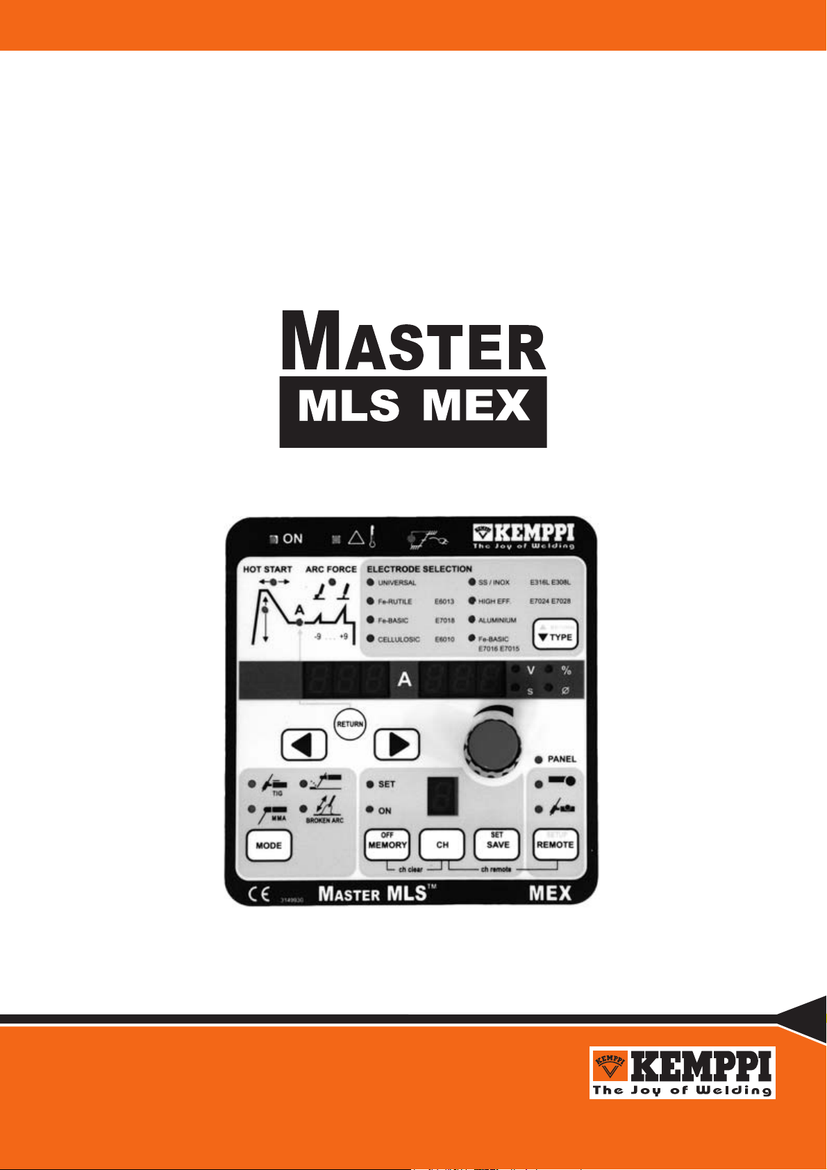
3.3. TYPE, SELECTION OF ELECTRODE TYPE (3)
Welding parameters settle automatically to optimum values according to selected
electrode type. You have seven different electrode types to choose from.
When selecting UNIVERSAL, the parameters are set to normal values. If the
initial state was UNIVERSAL select the electrode material you use by pressing
TYPE button (3) as many times as needed to point the right material from the list.
Backwards stepping is done by keeping the RETURN button down while pressing the TYPE button.
3.4. REGULATION OF WELDING CURRENT AND OTHER
PARAMETERS (4, 5, 6, 7)
To select welding parameters you only need to use two buttons (6): arrow-left
and arrow-right. Adjustment is done with the potentiometer (4).
By pressing the RETURN button, adjustment of parameter goes straight to welding current. The display (5) shows automatically numeric values and the units of
the parameters. When you adjust parameters, you can see the value on the numerical display. After 10 seconds, the display will return to the welding current.
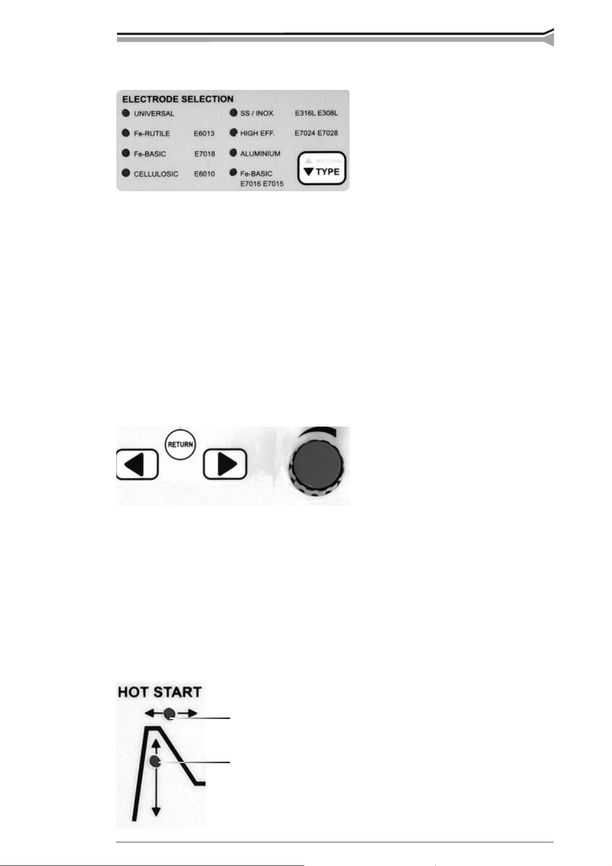
3.5. HOT START PULSE CONTROL (4, 5, 6, 7)
© COPYRIGHT KEMPPI OY
a
b
Select either pulse height (a) or pulse duration (b)
with the arrow buttons (6). Pulse height is shown
on display (5) in ampere and duration in seconds.
Adjust values with potentiometer when needed.
Master MLS MEX / 0241 – 7
Page 8

3.6. ARC FORCE CONTROL DYNAMICS (4, 5, 6, 7)
Select Arc Force with arrow buttons (6), in which case the
corresponding pilot lamp (7) is lit and the numerical value
is shown on display (5): -9…0…+9. With potentiometer
for regulation of welding parameters (4) you can adjust the
arc softer (-1…-9) or harder (+1…+9) when needed.
3.7. REMOTE CONTROL SELECTION (8)
local
control
When you want to adjust welding current
R 10
R11T
RTC 10
with a remote control unit, connect the unit
and select remote control with REMOTE
button (8). The pilot lamp on panel indicating local control is switched off; select the
remote control unit you need (hand remote
control unit R10, R11T if R10 is not fi tted,
or TIG torch potentiometer remote RTC10).
3.8. MEX MEMORY FUNCTIONS (9)
MEX panel has 10 memory channels for user settings. The selections for saving
are made on MEMORY fi eld (9). Not only welding parameters but also selections
are saved in the memory. MMA welding values can also be stored in memory
channels.
8 – Master MLS MEX / 0241
© COPYRIGHT KEMPPI OY
Page 9

Proceed as follows:
1. Press MEMORY button twice and if the SET light starts blinking,
the channel is free. If the channel is in use the led will remain lit.
2. Select memory channel by pressing CH button.
3. Select the parameters and press SAVE button.
4. Press MEMORY button twice. ON led is lit.
5. Start welding and adjust settings if necessary.
If saved settings need to be changed, the led has to be moved from ON into SET
position in order to select parameters. Press the SAVE button. It is also possible
to save the currently used parameters in the panel by pressing SET when the
memory function is in off state (no lights on). Channel is cleared if MEMORY
and CH buttons are pressed simultaneously in SET mode.
The saved settings are taken into use as follows:
1. Select MEMORY by pressing the button.
2. Select memory channel by pressing CH button.
3. Start welding.
Remote control of memory channels is accomplished as follows:
Memory channels are selected by pressing simultaneously both REMOTE and
CH button. With the remote control you can retrieve saved settings on memory
channels.
3.9. SETUP, PRESET VALUES OF WELDING PARAMETERS
MEX panel has special MMA-MEX Setup functions. Press
REMOTE (SETUP) button (8) longer than normally to
enter (or exit) the Setup mode. You can select the functions
(see list below) by pressing the arrow buttons and then
change the settings by turning the potentiometer.
FUNCTION NUMBER FACTORY SETTING
Hot start adjustment method: 1 knob or 2 knob A1 0 2 knob
Antifreeze on/off in TIG A3 0 off
Antifreeze on/off in MMA A4 1 on
Adaptive hot start on/off A5 0 off
No load voltage selection 80V / 40V A7 0 80V
Function of hand remote (normal remote current
regulation of MMA/TIG changeover)
A12 0 normal
© COPYRIGHT KEMPPI OY
Master MLS MEX / 0241 – 9
Page 10

KEMPPI OY
PL 13
FIN – 15801 LAHTI
FINLAND
Tel (03) 899 11
Telefax (03) 899 428
www.kemppi.com
KEMPPIKONEET OY
PL 13
FIN – 15801 LAHTI
FINLAND
Tel (03) 899 11
Telefax (03) 7348 398
e-mail: myynti.fi @kemppi.com
KEMPPI SVERIGE AB
Box 717
S – 194 27 UPPLANDS VÄSBY
SVERIGE
Tel (08) 59 078 300
Telefax (08) 59 082 394
e-mail: sales.se@kemppi.com
KEMPPI NORGE A/S
Postboks 2151, Postterminalen
N – 3103 TØNSBERG
NORGE
Tel 33 34 60 00
Telefax 33 34 60 10
e-mail: sales.no@kemppi.com
KEMPPI DANMARK A/S
Literbuen 11
DK – 2740 SKOVLUNDE
DANMARK
Tel 44 941 677
Telefax 44 941 536
e-mail:sales.dk@kemppi.com
KEMPPI BENELUX B.V.
Postbus 5603
NL – 4801 EA BREDA
NEDERLAND
Tel (076) 5717 750
Telefax (076) 5716 345
e-mail: sales.nl@kemppi.com
KEMPPI (U.K) Ltd.
4-6 Sergeants Way
Elms Industrial Estate
BEDFORD, MK 41 OEH
ENGLAND
Tel (01234) 213 581
Telefax (01234) 215 128
e-mail: sales.uk@kemppi.com
KEMPPI FRANCE S.A.
S.A. au capital de 5 000 000 F.
65 Avenue de la Couronne des Prés
78681 EPONE CEDEX
FRANCE
Tel (01) 30 90 04 40
Telefax (01) 30 90 04 45
e-mail: sales.fr@kemppi.com
KEMPPI GmbH
Otto – Hahn – Straße 14
D – 35510 BUTZBACH
DEUTSCHLAND
Tel (06033) 88 020
Telefax (06033) 72 528
e-mail:sales.de@kemppi.com
KEMPPI SP. z o.o.
Ul. Piłsudskiego 2
05-091 ZA¸BKI
Poland
Tel +48 22 781 6162
Telefax +48 22 781 6505
e-mail: info.pl@kemppi.com
KEMPPI SWITZERLAND AG
Chemin de la Colice 4
CH-1023 Crissier/ Lausanne
SUISSE
Tel. +41 21 6373020
Telefax +41 21 6373025
e-mail: sales.ch@kemppi.com
KEMPPI WELDING
MACHINES AUSTRALIA PTY LTD
P.O. Box 404 (2/58 Lancaster Street)
Ingleburn NSW 2565, Australia
Tel. +61-2-9605 9500
Telefax +61-2-9605 5999
e-mail: info@kemppi.com.au
Ver. 5
www.kemppi.com
 Loading...