

Page 1
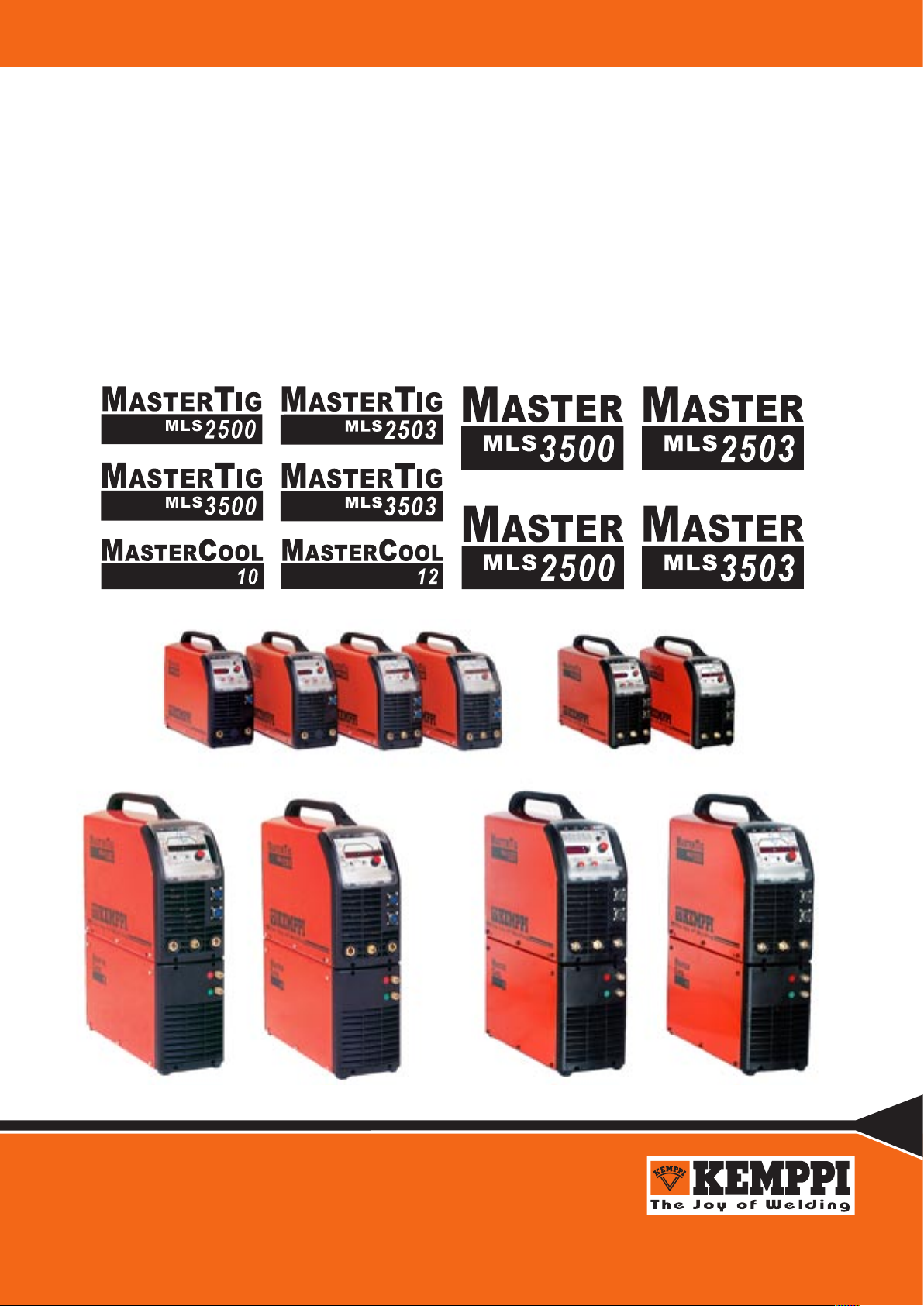
Operation instructions • english
Gebrauchsanweisung • deutsch
Gebruiksaanwijzing • nederlands
Manuel d’utilisation • français
1910030E
0311
Page 2

2 – Master(tig) 2500, 2503, 3500, 3503 MLS™/ 0311
© COPYRIGHT KEMPPI OY
Master(tig) 2500, 2503, 3500, 3503 MLS™/ 0311 – 3
© COPYRIGHT KEMPPI OY
CONTENTS
1. PREFACE........................................................................................................................ 3
1.1. Introduction ............................................................................................................................... 3
1.2. Product introduction.................................................................................................................. 3
1.3. Operation safety .......................................................................................................................3
2. INSTALLATION ...............................................................................................................4
2.1. Removal from packaging ..........................................................................................................4
2.2. Locating the machine................................................................................................................ 4
2.3. Serial number ...........................................................................................................................4
2.4. Installation and main parts........................................................................................................ 4
2.5. Installation of the panel............................................................................................................. 5
2.6. Mains connection...................................................................................................................... 5
2.7. Welding cable connections ....................................................................................................... 6
2.7.1. Choosing welding polarity in MMA welding .............................................................................. 6
2.7.2. Earthing .................................................................................................................................... 6
2.8. Cooling unit (Mastercool 10, Mastercool 12) ............................................................................6
2.9. Shield gas .................................................................................................................................7
2.9.1. Installation of gas bottle............................................................................................................ 7
3. OPERATION.................................................................................................................... 8
3.1. Welding processes....................................................................................................................8
3.1.1. MMA welding ............................................................................................................................ 8
3.1.2. TIG welding .............................................................................................................................. 8
3.1.3. Synergetic Pulsed TIG welding ................................................................................................ 8
3.1.4. Long Pulsed TIG welding ........................................................................................................ 8
3.2. Operation functions................................................................................................................... 8
3.2.1. Power source............................................................................................................................ 8
3.2.2. Function panels (MTL,MTX, MTZ, MTM, MEL, MEX) .............................................................8
3.2.2.1. Indicator lights .................................................................................................... 9
3.2.2.2. MMA welding panel MEL.................................................................................... 9
3.2.2.3. MMA welding panel MEX ................................................................................. 10
3.2.2.4. TIG welding panel MTL .................................................................................... 11
3.2.2.5. TIG welding panel MTX.................................................................................... 13
3.2.2.6. TIG welding panel MTZ ................................................................................... 14
3.2.2.7. TIG welding panel MTM ................................................................................... 15
3.2.3. Saving welding settings (MTM) .............................................................................................. 16
3.2.4. Adopting the saved settings.................................................................................................. 16
3.2.5. Remote control memory channels.......................................................................................... 16
3.2.6. SETUP functions .................................................................................................................... 16
3.2.7. Foot pedal control R11F ......................................................................................................... 17
3.3. Cooling unit operation (Mastercool 10, Mastercool 12) ..........................................................17
3.4. Storage ................................................................................................................................... 17
4. MAINTENANCE ............................................................................................................18
4.1. Regular maintenance.............................................................................................................. 18
4.1.1. Every sixth months ................................................................................................................. 18
4.1.2. Service contract...................................................................................................................... 18
4.2. Troubleshooting ...................................................................................................................... 18
4.3. Disposal of the machine .........................................................................................................19
5. ORDERING NUMBERS ................................................................................................19
6. TECHNICAL DATA........................................................................................................ 21
Page 3

Master(tig) 2500, 2503, 3500, 3503 MLS™/ 0311 – 3
© COPYRIGHT KEMPPI OY
1. PREFACE
1.1. INTRODUCTION
Congratulations on having purchased a KEMPPI product. Properly installed and used Kemppi products should prove to be productive machines requiring a small amount of regular maintenance. This
manual is to give you a good understanding of the equipment and its safe operation. It also contains
maintenance information and technical specications. Read this manual completely from front to back
before installing, operating or maintaining the equipment for the rst time. For further information on
Kemppi products please contact us or your nearest Kemppi distributor.
The specications and designs presented in this manual are subject to change without prior notice.
In this document, for danger to life or injury the following symbol is used:
Read the warnings carefully and follow the instructions. Please also study the Operation safety
instructions and respect them when installing, operating and servicing the machine.
1.2. PRODUCT INTRODUCTION
Kemppi Master 2500, 2503, 3500 and 3503 MLS™ is a MMA welding machine designed for industrial use and for welding all kinds of covered electrodes, including difcult-to-weld types such as
cellulose electrodes. The equipment consists of power source, welding cables and function panel.
Kemppi Mastertig 2500, 2503, 3500 and 3503 MLS™ is a TIG welding system especially designed
for industrial use and for welding e.g. stainless steel materials. The equipment consists of a power
source, function panel, TIG welding torch, ground cable and an optional cooling unit. The cooling unit
(Mastercool 10, Mastercool 12) is used in water-cooled TIG welding.
The power source is a multifunctional machine for demanding professional use for MMA, TIG and
pulsed TIG welding with direct current. The power source is controlled with IGBT transistors with a
frequency of approximately 20 kHz, and the operational functions with a microprocessor. The welding
torch can be either water-cooled or gas-cooled.
1.3. OPERATION SAFETY
Please study these Operation safety instructions and respect them when installing, operating and servicing the machine.
Welding arc and spatters
Welding arc hurts unprotected eyes. Be careful also with reecting arc ash. Welding arc and spatter
burn unprotected skin. Use safety gloves and protective clothing.
Danger for re or explosion
Pay attention to re safety regulations. Remove ammable or explosive materials from welding place.
Always have sufcient re-ghting equipment wherever you are welding. Be prepared for hazards in
special welding jobs, e.g. for danger of re or explosion when welding container-type work pieces.
Note! Fire can break out from sparks even several hours after the welding work has been nished!
Mains voltage
Never take welding machine inside a work piece (e.g. container or truck). Do not place welding
machine on a wet surface. Always check cables before operating the machine. Change damaged
cables without delay. Damaged cables may cause an injury or start a re. Connection cable must not
be crushed, it must not touch sharp edges or hot work pieces.
Page 4
4 – Master(tig) 2500, 2503, 3500, 3503 MLS™/ 0311
© COPYRIGHT KEMPPI OY
Master(tig) 2500, 2503, 3500, 3503 MLS™/ 0311 – 5
© COPYRIGHT KEMPPI OY
1
2
3
5
4
6
Welding power circuit
Isolate yourself by using proper protective clothing, do not wear wet clothing. Never work on a
wet surface or use damaged cables. Do not put TIG torch or welding cables on welding machine
or on other electric equipment. Do not press TIG torch switch if the torch is not directed towards
the work piece.
Welding fumes
Take care that there is sufcient ventilation during welding. Take special safety precautions
when welding metals which contain lead, cadmium, zinc, mercury or beryllium.
Lifting the equipment
Always remove gas bottle before lifting.
2. INSTALLATION
2.1. REMOVAL FROM PACKAGING
The equipment is packed in durable packages designed especially for it. However, it is necessary to check the equipment before using it to make sure that the equipment or any part of it has
not got damaged during transportation. Also check that the delivery corresponds to your order
and that you have received all necessary instructions for installing and operating the equipment.
The packaging material is recyclable.
2.2. LOCATING THE MACHINE
Place the machine on a horizontal, stable and clean ground. Protect the machine from rain and
direct sunshine. Check that there is enough space for cooling air circulation in front of and
behind the machine.
2.3. SERIAL NUMBER
Serial number of the machine is marked on the rating plate. The serial number is the only proper
means of identifying parts for a specic product. It is important to make correct reference to the
serial number of the product when making repairs or ordering spare parts.
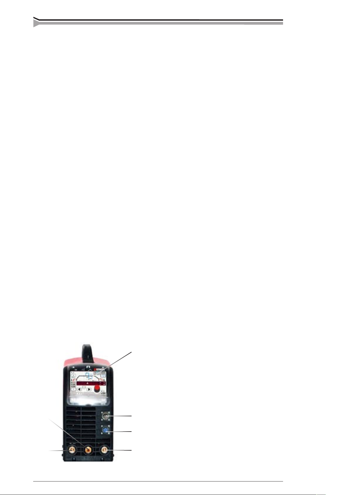
2.4. INSTALLATION AND MAIN PARTS
Front of machine
1. Function panel
2. Remote control connector
3. TIG torch control connector, not in MMA version
4. Shield gas and current connector for TIG torch, not in MMA
version
5. (+) connector for electrode holder or earth cable, in TIG welding for earth cable
6. (-) connector for earth cable or electrode holder in MMA
welding (stick welding)
Markings for (+/-) poles on the machine front are embossed.
Page 5
© COPYRIGHT KEMPPI OY
1
2
1.
2.
Master(tig) 2500, 2503, 3500, 3503 MLS™/ 0311 – 5
Rear of machine
1. Mains switch
2. Snap connector for gas
Torch Installing gas-cooled
torch
Installing water-cooled torch
2.5. INSTALLATION OF THE PANEL
1. Fasten the cable connectors of the function panel to the power source (2 pieces).
2. Place the bottom edge of the panel behind the securing clips on the machine. Remove the
fixing pin from the top edge with, for example, a screwdriver. Then gently push the upper part
of the panel into place. Make sure that the cables do not get damaged, continue gently pushing
the upper part of the panel until it clips into place. Finally, push the fixing pin back into its
place.
2.6. MAINS CONNECTION
Only an authorised electrician is allowed to install mains cable and plug!
The power source is equipped with a 5-meter mains cable without plug. The plug may be installed by an authorised electrician only. The fuse and cable sizes are given in the Technical data at
the end of this manual.
Page 6
6 – Master(tig) 2500, 2503, 3500, 3503 MLS™/ 0311
© COPYRIGHT KEMPPI OY
Master(tig) 2500, 2503, 3500, 3503 MLS™/ 0311 – 7
© COPYRIGHT KEMPPI OY
2.7. WELDING CABLE CONNECTIONS
2.7.1. Choosing welding polarity in MMA welding
You can change the welding polarity by choosing (+) or (-) cable connector.
2.7.2. Earthing
If possible, always fasten the earth clamp of return current cable directly onto work piece.
1. Clean contact surface of earth clamp from paint and rust.
2. Fasten clamp properly, so that contact surface is as large as possible.
3. Check that clamp is fastened rmly.
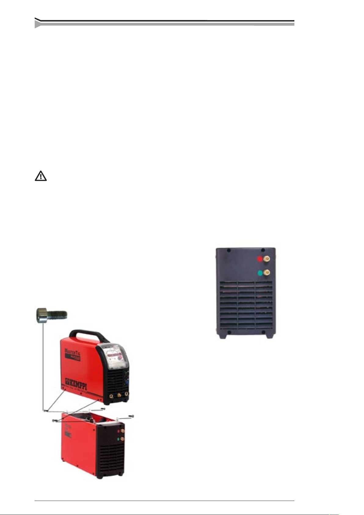
2.8. COOLING UNIT (MASTERCOOL 10, MASTERCOOL 12)
Cooling liquid is injurious! Avoid also contact with skin or eyes. In case of injury,
seek for medical advice.
Cooling unit Mastercool 10 and Mastercool 12 together with TIG torch of Kemppi’s TTC-W
range enables TIG welding with water-cooled torch.
The cooling unit is installed beneath the power source with screws. Electrical connections are
on the bottom of power source. Fill the reservoir with a 20 - 40 % mixture of glycol and water,
or with any other suitable antifreeze. The capacity of the reservoir is 3 litres.
Mastercool 10: Mastercool 12:
Mastertig 2500 MLS™ Mastertig 2503 MLS™
Mastertig 3500 MLS™ Mastertig 3503 MLS™
Installation of cooling unit
Page 7
Master(tig) 2500, 2503, 3500, 3503 MLS™/ 0311 – 7
© COPYRIGHT KEMPPI OY
A
C
F
G
B
E
D
2.9. SHIELD GAS
Handle gas bottle with care. There is a risk for injury if gas bottle or bottle valve is
damaged!
Use inert gases such as argon, helium or argon-helium mixture as shield gas for TIG welding.
Make sure that the gas ow regulator is suitable for the gas type used. The ow rate is set
according to the welding current, joint form and the size of the electrode. A suitable ow rate
is normally 8 – 10 l/min. If the gas ow is not suitable the welded joint will be porous. Spark
ignition becomes more difcult if the gas ow is too high. Contact your local Kemppi dealer for
choosing gas and equipment.
2.9.1. Installation of gas bottle
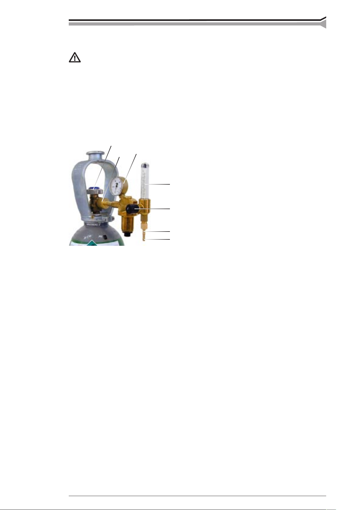
Parts of gas ow regulator
A Gas bottle valve
B Pressure regulation screw
C Connecting nut
D Hose spindle
E Jacket nut
F Gas bottle pressure meter
G Gas hose pressure meter
Always fasten gas bottle properly in vertical position in a special holder on the wall or on a
carriage. Remember to close gas bottle valve after having nished welding.
The following installation instructions are valid for most gas ow regulator types:
1. Step aside and open the bottle valve (A) for a while to blow out possible impurities
from the bottle valve. Note! Watch out for the gas ow.
2. Turn the press regulation screw (B) of the regulator until no spring pressure can be felt.
3. Close needle valve if there is one in the regulator.
4. Install the regulator on bottle valve and tighten connecting nut (C) with a wrench.
5. Install hose spindle (D) and jacket nut (E) into gas hose and tighten with hose clamp.
6. Connect one end of the hose with the regulator and the other end with the power source.
Tighten the jacket nut.
7. Open bottle valve slowly. Gas bottle pressure meter (F) shows the bottle pressure.
Note! Do not use the whole contents of the bottle. The bottle should be lled when the
bottle pressure is 2 bar.
8. Open needle valve if there is one in the regulator.
9. Turn regulation screw (B) until hose pressure meter (G) shows the required ow (or
pressure). When regulating ow amount, the power source should be switched on and
the gun switch pressed simultaneously.
Close bottle valve after having nished welding. If the machine will be out of use for a long
time, unscrew the pressure regulation screw.
Page 8

8 – Master(tig) 2500, 2503, 3500, 3503 MLS™/ 0311
© COPYRIGHT KEMPPI OY
Master(tig) 2500, 2503, 3500, 3503 MLS™/ 0311 – 9
© COPYRIGHT KEMPPI OY
(a)
(b)
3. OPERATION
Welding in places presenting an immediate re or explosion hazard is forbidden!
Welding fumes may cause injury, take care of sufcient ventilation during welding!
3.1. WELDING PROCESSES
3.1.1 MMA welding
MMA welding, as well as carbon arc gouging, is possible with all Master MLS and Mastertig
MLS power sources with all MLS panel versions when switched to MMA process.
3.1.2 TIG welding
Mastertig MLS power sources are designed especially for TIG welding. They are equipped with
HF spark ignition and versatile panel functions depending on the panel used. The panels predominantly for TIG welding are MTL, MTX, MTZ and MTM. Also the MEL and MEX panel on
Master MLS power source can be used for TIG welding with contact ignition.
3.1.3 Synergetic Pulsed TIG welding (a)
MTX, MTZ and MTM panels include the synergetic pulsed TIG process, in which you only need to adjust the welding current while other
pulse parameters are programmed. Pulsing frequency is high, which
guarantees concentrated arc and increased welding speed.
3.1.4 Long Pulsed TIG welding (b)
This method gives you the possibility to adjust all pulse parameters.
Weld pool control is also easier. Long pulsed TIG welding is included
in MTX, MTZ and MTM panels.
3.2. OPERATION FUNCTIONS
3.2.1. Power source
Always switch the machine on and off from main switch. Do not use the mains plug
for switching!
Never watch the arc without a proper face shield designed for arc welding! Protect
yourself and the surroundings against welding arc and hot spatters!
3.2.2. Function panels
Before welding starts, welding settings suitable for the work piece are chosen with the function
panel. See 3.1. Welding processes.
The Kemppi Multi Logic System, MLS, allows you to select from different function panels
according to your welding application. MEL and MEX panels are designed for MMA welding.
MTL, MTX, MTZ and MTM panels are for TIG welding with basic functions, or with pulsed
TIG, 4T-LOG, or MINILOG control of welding current, or with memory channels. See also 3.1.
Welding processes.
Page 9

Master(tig) 2500, 2503, 3500, 3503 MLS™/ 0311 – 9
© COPYRIGHT KEMPPI OY
1 2
3
1
2
3
4
5
6
7
8
3.2.2.1. Indicator lights
1. Power On
2. Thermal overload of power source
3. Wrong mains voltage, over or under-voltage
3.2.2.2. MMA welding panel MEL
1. Remote/local control switch
2. Welding current potentiometer
3. Contact TIG welding
4. MMA welding
5. Arc force
6. Hot start
7. Digital display and amperage/voltage switch
8. Welding current table
Page 10

10 – Master(tig) 2500, 2503, 3500, 3503 MLS™/ 0311
© COPYRIGHT KEMPPI OY
Master(tig) 2500, 2503, 3500, 3503 MLS™/ 0311 – 11
© COPYRIGHT KEMPPI OY
3
4
8
9
1
7
5
6
2
3.2.2.3. MMA welding panel MEX
MEX panel is available separately. The functions of MEX panel are described in the operating
manual delivered with the panel.
1. Indicator lights: Main switch, overheating, wrong mains voltage
2. MODE button for welding method selection: MMA, contact TIG, carbon arc gouging, broken arc
3. Selection of electrode type
4. Potentiometer for regulation of welding current and other parameters
5. Displays of welding current and other parameters (A, V, s, mm)
6. Selection of welding parameter to be regulated (arrow button to the left / to the right, focusing
(RETURN))
- Hot start regulation (HOT START)
- Welding current (A)
- Arc force control dynamics (ARC FORCE)
7. Figure indicating selection of welding parameter: HOT START, A, ARC FORCE
8. Selection of remote control / SETUP function
9. Memory functions
Page 11

Master(tig) 2500, 2503, 3500, 3503 MLS™/ 0311 – 11
© COPYRIGHT KEMPPI OY
12
13
14
8
6
3
1
2
7
4
9
5
10
11
3.2.2.4. TIG welding panel MTL
- basic functions
1. Selection of MMA welding
2. Selection of arc force (MMA) and pedal low/high (minimum and maximum welding current)
displays and regulation (TIG welding)
3. Selection of hot start (MMA) and gas test (TIG welding)
4. Selection of TIG welding, 4T and 2T functions of torch switch
5. Selection of HF/contact and water ll function
6. Selection of panel, foot pedal and remote control
7. Selection of welding parameters
8. Adjustment of welding parameters
9. Pre-gas 0 - 10 s
10. Upslope 0 - 10 s
11. Welding current
12. Downslope 0 - 15 s
13. Post-gas 1 - 30 s
14. Return to welding current
Page 12

12 – Master(tig) 2500, 2503, 3500, 3503 MLS™/ 0311
© COPYRIGHT KEMPPI OY
Master(tig) 2500, 2503, 3500, 3503 MLS™/ 0311 – 13
© COPYRIGHT KEMPPI OY
1. MMA
Select MMA welding by pressing the selection button of MMA welding. The led is lit when
MMA is on.
2. Arc force
Press the arc force button and you will see the numerical value corresponding to the MMA
dynamics in the display. Factory setting for all electrode types is zero. You can change the value
by turning the pulse potentiometer. If numerical value is adjusted negative (-1...9) the arc is softened, and the amount of spatter decreases when welding at the upper end of the recommended
current range of the electrode. On the positive side (1...9) the arc is rough.
In TIG mode, you can select the max. and min. current for the foot pedal (PEDAL LO/HI).
3. Hot start
When pressing the hot start button, you will see on the display the numerical value corresponding to the MMA hot start pulse. You can adjust the value by turning the potentiometer. In TIG
mode you can select gas test function.
4. TIG welding is selected
4. Welding torch switch 2 sequence function
Gas ow starts when the torch switch is pressed. After preset pre-gas time welding starts, and
current will rise to the welding level within the up-slope time. Release the torch switch, and the
current starts to drop, and after the selected down-slope time the arc is broken. After this, the
shield gas will ow for the time selected.
4. Welding torch switch 4 sequence function
Gas ow starts when the torch switch is pressed. Release the torch switch. The ignition spark
ignites the arc, and the current will rise to the welding level within the up-slope time. Press the
torch switch down, and the welding continues. Release the torch switch, and the current starts to
drop and after the selected down-slope time the arc is broken. After this, the shield gas will ow
for the time selected.
5. HF/contact ignition in TIG welding (water ll)
TIG arc can be started either with high frequency (HF) or without (contact ignition). HF ignition
is chosen by pressing the HF CONTACT button (5) to turn on the HF light.
If you use water-cooled torch you can ll it with water by pressing the HF CONTACT button
for more than 2 seconds.
6. Remote control
If you choose to adjust the welding current with a remote control unit you need to connect the
unit and select the REMOTE button. The panel led switches off and you can select the unit
(R10, wireless remote control R11T for MMA welding, or foot pedal control R11F). There is
an automatic recognition of remote control units with potentiometers and only the symbol of a
connected unit can be chosen. The foot pedal control works only in 2T mode.
7., 8. and 14. Adjustment of parameters
To select TIG welding parameters you only need to use two buttons: arrow-left and arrow-right.
Adjustment is done with the potentiometer. When pressing the RETURN button, adjustment of
parameters goes straight to welding current. The display shows automatically numeric values
and the units of the parameters. When you adjust the parameters, you can see the value on the
numerical display. After 10 seconds, the display will return to the welding current.
Page 13

Master(tig) 2500, 2503, 3500, 3503 MLS™/ 0311 – 13
© COPYRIGHT KEMPPI OY
2
9
8
7
4
5
3
6
1
3.2.2.5. TIG welding panel MTX
- pulsed TIG functions
1. 4T-LOG
2. Selection for spot, synergetic quick pulse and long pulse
3. Search arc 10 – 80 % of welding current
4. Pulse current 10 A – max.
5. Pulse ratio 10 – 70 % of pulse time
6. Frequency 0.2 – 300 Hz
7. Base current 10 – 70 % of pulse current
8. Spot time 0 – 10 s
9. Tail arc 10 – 80 % of welding current
1. Welding torch switch 4T-LOG function (only MTX panel)
When torch switch is pressed current goes to search arc; after the switch is released current goes
to welding current within the upslope time. When the switch is pressed again, current goes to
downslope and then to the tail arc. Current stops when the switch is released.
2. Spot
Spot function is practical when welding a denite spot with TIG. It can be used both in 2T and
4T mode. Enter the spot time adjustment by pressing arrow button, and when the led is lit you
can choose the spot time needed by turning the pulse potentiometer.
Page 14

14 – Master(tig) 2500, 2503, 3500, 3503 MLS™/ 0311
© COPYRIGHT KEMPPI OY
Master(tig) 2500, 2503, 3500, 3503 MLS™/ 0311 – 15
© COPYRIGHT KEMPPI OY
1
2
2. Synergetic quick pulse
Press the PULSE button twice and the synergetic light turns on. Pulse parameters are calculated
automatically when average welding current is selected. Other pulse selections are not necessary.
2. Long pulse
Long pulse method gives you the possibility to adjust all pulse parameters (pulsing frequency,
pulse ratio, pulse current and pause current). You can also adjust the welding current, in which
case you receive a new pulse current value. Pulse ratio and pause current percentage remain
constant. When you adjust the pulse ratio, pulse current or pause current, the new average welding current value is shown on the display.
3.2.2.6. TIG welding panel MTZ
- pulsed TIG and MINILOG function
1. Minilog
2. Minilog 10 – 90 % of welding current
1. MTZ Minilog
When torch switch is pressed current goes to search arc; after the switch is released current goes
to welding current within the upslope time. With Minilog operation you can select from two
current levels: the welding current and the Minilog current. You can move from one to the other
by quickly pressing the torch switch. Press torch switch for 1 second, current goes to downslope
and then to the tail arc. Current stops when the switch is released.
Page 15

Master(tig) 2500, 2503, 3500, 3503 MLS™/ 0311 – 15
© COPYRIGHT KEMPPI OY
5
32
1
4
1. Minilog
2. Selection of memory function
3. Selection of channel in memory function
4. Minilog 10 – 90 % of welding current
5. SAVE
1. Minilog operation
When torch switch is pressed gas ow starts. When you release the switch current goes to
search arc. A quick press on the switch, and current goes to welding current within the upslope
time. After another short press it goes to Minilog operation, and you can select from two current levels: the welding current and the Minilog current. You can move from one to the other by
quickly pressing the torch switch. Press the torch switch for 1 second, release it and current goes
to downslope.
3.2.2.6. TIG welding panel MTM
- pulsed TIG and MINILOG function with memory
Page 16

16 – Master(tig) 2500, 2503, 3500, 3503 MLS™/ 0311
© COPYRIGHT KEMPPI OY
Master(tig) 2500, 2503, 3500, 3503 MLS™/ 0311 – 17
© COPYRIGHT KEMPPI OY
3.2.3. Saving welding settings (MTM)
MTM panel has 10 memory channels for user settings. The selections are made in the MEMORY
eld. Not only welding parameters but also function selections can be saved in the memory. MMA
welding values can also be stored in memory channels. Proceed as follows:
1. Press MEMORY button twice and if the SET light starts blinking the channel is free. If
the channel is reserved the led will remain lit.
2. Select memory channel by pressing CH button.
3. Select the parameters and press SAVE button.
4. Press MEMORY button twice. ON led is lit.
5. Start welding and adjust settings if necessary.
If the saved settings need to be adjusted the led has to be moved from ON to SET position in order
to select parameters. Press the SAVE button. It is also possible to save the currently used parameters by pressing SET when the memory function is in OFF state (no lights on). Channel is cleared if
MEMORY and CH buttons are pressed simultaneously in SET mode.
3.2.4. Adopting the saved settings
1. Select MEMORY by pressing the button.
2. Select memory channel by pressing the CH button.
3. Start welding.
3.2.5. Remote control memory channels
Memory channels are selected by pressing simultaneously both REMOTE and CH button. With the
remote control you can retrieve saved settings on memory channels.
3.2.6. SETUP functions
A so called SETUP state is included for modifying panel functions. You can enter the SETUP state
by pressing the REMOTE (SETUP) button longer than normally. Exit is performed in the same
way. You can select the function (see list below) by pressing the arrow buttons and then change the
setting by turning the potentiometer.
Display Function Factory setting
A1 Upslope with constant time setting / gradient (steepness) setting 0 constant time
A2 Downslope with constant time setting / gradient (steepness) setting 0 constant time
A3 TIG antifreeze off / on 1 off
A4 MMA antifreeze off / on 1 on
A5 MMA hot start pulse non adaptive / adaptive 0 non adaptive
A6 Downslope cut off on / off 0 on
A7 MMA open circuit voltage 80V / 40V 0 80V
A8 2T downslope normal / cuts off by short switch action 0 normal
A9 Tacking automatics off / on 0 off
A10 Current at arc start steep / slightly sloped 0 steep
A11 Downslope linear / non-linear 0 linear
A12 MMA/TIG method selection with remote control off /on 0 off
A13 Search arc off / on 1 on
A14 Possibility to current freezing during downslope off / on 0 off
A15 Control of channels with torch up-down switch off / on 0 off
Page 17

Master(tig) 2500, 2503, 3500, 3503 MLS™/ 0311 – 17
© COPYRIGHT KEMPPI OY
A16 Control of current with torch up-down switch always active / active only when selected
with REMOTE button 0 always active
A17 Guard functions of cooling unit not activated / activated 1 activated
A18 Downslope for Minilog and 4T in MTM and MTL panels performed during long switch
action / after switch operation (normal) 0 normal
A19 Cooling unit operates on forced control / automatic on/off control 0 automatic
3.2.7. Foot pedal control R11F
First read under “3.2.2.4. TIG welding panel MTL” point “6. Remote control” for installing
the remote control ready for operation. Foot pedal R11F is used in TIG welding, and its control
range is adjustable. The minimum value of control range is set with the panel potentiometer
when the pedal is not pressed, display shows “LO”. Control range maximum is set similarly by
pressing rst the PEDAL LO/HI button on the panel, display shows “HI”. Welding is started
with a light press on the pedal, the arc ignites to the set minimum current. Welding current
goes to maximum when the pedal is pressed to the bottom. The arc is broken when the pedal is
released. Adjust again if necessary.
3.3. COOLING UNIT OPERATION
(MASTERCOOL 10, MASTERCOOL 12)
The operation of cooling units Mastercool 10 and Mastercool 12 is controlled by the power
source. The cooling unit pump starts automatically when welding starts. Proceed as follows:
1. Start power source.
2. Check water level and input ow of the reservoir, add liquid if needed.
3. If you use a water-cooled torch you can ll it with water by pressing WATER FILL
(HF CONTACT) button for more than 2 seconds.
The pump operates for 5 another minutes after welding has been nished to cool the water to the
same temperature as in the machine surrounds. This reduces the need of service.
Thermal overload
The thermal overload light is lit, the machine stops and display shows COOLER when temperature control of the machine has detected cooling water overheating. The cooling unit fan cools
down the water, and when the light goes out welding can be started again.
Water ow signal
Display shows COOLER when water ow is blocked.
3.4. STORAGE
The machine must be stored in a clean and dry room. Protect the machine from rain and direct
sunshine in places where temperature exceeds +25 °C.
Page 18

18 – Master(tig) 2500, 2503, 3500, 3503 MLS™/ 0311
© COPYRIGHT KEMPPI OY
Master(tig) 2500, 2503, 3500, 3503 MLS™/ 0311 – 19
© COPYRIGHT KEMPPI OY
4. MAINTENANCE
Watch out for mains voltage when handling electric cables!
Degree and circumstances of machine utilisation should be taken into consideration when planning product maintenance. Careful use and preventive maintenance help to avoid unnecessary
production disturbances and breaks. Check the condition of the welding and connection cables
daily. Do not use damaged cables.
4.1. REGULAR MAINTENANCE
4.1.1. Every sixth months
NOTE! Disconnect the plug of the machine from the mains socket and wait for ca. 2 minutes
(capacitor charge) before removing the casing plate.
The following maintenance operations should be carried out at least every sixth months:
• Electric connections of the machine - clean any oxidised parts and tighten any loose
ones. NOTE! You must know the correct tension torques before you start repairing
the connections.
• Clean the inner parts of the machine from dust and dirt e.g. with a soft brush and a
vacuum cleaner. Do not use compressed air because there is the danger that the dirt
is packed even more tightly in the gaps of the cooling proles. Do not use a pressure
washer.
Only an authorised electrician may repair the machine.
4.1.2. Service contract
KEMPPI service workshops make special service contracts with customers about regular maintenance. All parts are cleaned, checked and if necessary, repaired. Also the operation of welding
machine is tested.
4.2. TROUBLESHOOTING
Power On light is not lit.
There is no power in the machine.
• Check mains fuses, replace blown fuses.
• Check mains cable and plug, replace defect parts.
The machine is not welding properly.
There are plenty of spatters during welding. Weld joint is porous or power supply is insufcient.
• Check welding settings and adjust if needed.
• Check gas ow and gas hose connection.
• Check that earth clamp is properly fastened and that earth cable has no defects.
Change the position if necessary and replace defect parts.
• Check welding torch cable and connector. Tighten the connection and replace
defective parts.
• Check the consumable parts of welding torch. Clean and replace defect parts.
• Check mains fuses, replace blown fuses.
Page 19

Master(tig) 2500, 2503, 3500, 3503 MLS™/ 0311 – 19
© COPYRIGHT KEMPPI OY
Power source overheat indicator light is lit.
Power source is overheated.
• Check that there is enough free space behind the machine for cooling air circulation.
• Check cooling unit for water circulation, clean cooling unit lter and air grate. Add
cooling liquid if necessary.
For further information and assistance, contact your nearest Kemppi service workshop.
4.3. DISPOSAL OF THE MACHINE
Kemppi machines are produced mainly of recyclable materials. Please deliver an old machine
to be removed from service to a treatment plant where it is possible to separate the materials for
recycling.
4.2. ORDERING NUMBERS
Master 2500 MLS 6104250
Master 2503 MLS 6102250
Welding cable 35mm², 2,5 m 6184301
Earth cable 25mm², 2,5 m 6184311
Electric plug 16 A, 5-poles 9770812
Master 3500 MLS 6104350
Master 3503 MLS 6102350
Welding cable 50mm², 2,5 m 6184501
Earth cable 50mm², 2,5 m 6184511
Electric plug 16 A, 5-poles 9770812
Mastertig 2500 MLS 6114250
Mastertig 2503 MLS 6112250
Torches
TTC 160 4m 627016004
TTC 160 8m 627016008
TTC 160 16m 627016016
TTC 220 4m 627022004
TTC 220 8m 627022008
TTC 220 16m 627022016
Earth cable 35mm², 5 m 6184311
Electric plug 16 A, 5-poles 9770812
Gas ow meter AR/clock 6265136
Mastertig 3500 MLS 6114350
Mastertig 3503 MLS 6112350
Torches
TTC 160 4m 627016004
TTC 160 8m 627016008
TTC 160 16m 627016016
Page 20

20 – Master(tig) 2500, 2503, 3500, 3503 MLS™/ 0311
© COPYRIGHT KEMPPI OY
Master(tig) 2500, 2503, 3500, 3503 MLS™/ 0311 – 21
© COPYRIGHT KEMPPI OY
TTC 220 4m 627022004
TTC 220 8m 627022008
TTC 220 16m 627022016
Earth cable 35mm², 5 m 6184311
Electric plug 16 A, 5-poles 9770812
Gas ow meter Ar/clock 6265136
Mastercool 10 6122350
Mastercool 12 6122360
Water-cooled torches
TTC 200W 4m 627020504
TTC 200W 8m 627020508
TTC 200W 16m 627020516
TTC 250W 4m 627025504
TTC 250W 8m 627025508
TTC 250W 16m 627025516
Panels
MEL, MMA 6106000
MEX, MMA 6106010
MTL, TIG 6116000
MTX, TIG 4T-LOG 6116005
MTZ, TIG MINILOG 6116015
MTM, TIG MEMORY 6116010
Optional device
TIG torch controls
RTC 10 6185477
RTC 20 6185478
Remote control
R 10 6185409
R11T 6185442
R11F 6185407
Transport unit
T100 6185250
T110 6185251
T130 6185222
T200 6185258
Page 21

Master(tig) 2500, 2503, 3500, 3503 MLS™/ 0311 – 21
© COPYRIGHT KEMPPI OY
5. TECHNICAL DATA
MASTER MLS™ AND MASTERTIG MLS™ WELDING SYSTEM
Power source Master(tig)3500 MLS, Master(tig) 3503 MLS
Mains voltage 3~400V –15%…+10% (Mastertig 3500 MLS)
3~400V –15%…+20% (Master 3500 MLS)
3~230V –15%…+10% (Mastertig 3503 MLS)
3~230V –15%…+15% (Master 3503 MLS)
Rated power 40% ED MMA 350A
60% ED MMA 285A
100% ED MMA 220A
30% ED TIG 400A
60% ED TIG 285A
100% ED TIG 220A
Connection cable/fuse 4 x 2.5S mm² - 5 m/16 A delayed (Master(tig) 3500 MLS)
4 x 6S mm² - 5 m/32 A delayed (Master(tig) 3503 MLS)
Welding current range MMA 10 A/20.5V...350A/34.0V
(nominal values) TIG 5A/10.0V...400A/26.0V
Max welding voltage 45.0V/350A
Electrode sizes to be welded Ø1.5...6.0 mm
Welding current control stepless
Open circuit voltage 80V
Efciency 86% (350A/34,0V)
Power factor 0.95 (350A/34,0 V)
Open circuit power approx. 10 W
External dimensions length 500mm
width 180mm
height 390mm (650mm: TIG power source + cooling unit)
weight, TIG 23 kg
MMA 21 kg
Power source Master(tig) 2500 MLS, Master(tig) 2503 MLS
Mains voltage 3~400V –15%…+10% (Mastertig 2500 MLS)
3~400V –15%…+20% (Master 2500 MLS)
3~230V –15%…+10% (Mastertig 2503 MLS)
3~230V –15%…+15% (Master 2503 MLS)
Rated power 40% ED MMA 250A
60% ED MMA 205A
100% ED MMA 160A
30% ED TIG 300A
60% ED TIG 205A
100% ED TIG 160A
Page 22

22 – Master(tig) 2500, 2503, 3500, 3503 MLS™/ 0311
© COPYRIGHT KEMPPI OY
Master(tig) 2500, 2503, 3500, 3503 MLS™/ 0311 – 23
© COPYRIGHT KEMPPI OY
Connection cable/fuse 4 x 1.5S mm² - 5 m/10 A delayed (Master(tig) 2500 MLS)
4 x 2.5S mm² - 5 m/20 A delayed (Master(tig) 2503 MLS)
Welding current range MMA 10 A/20.5V...250A/30.0V
(nominal values) TIG 5A/10.0V...300A/22.0V
Max. welding voltage 36.0V/250A
Electrode sizes to be welded Ø1.5...5.0 mm
Welding current control stepless
Open circuit voltage 80V
Efciency 86 % (250A/30.0V)
Power factor 0.95 (250A/30.0V)
Open circuit power approx. 10 W
External dimensions length 500 mm
width 180 mm
height 390 mm (650 mm: TIG power source + cooling unit)
weight, TIG 22 kg
MMA 20 kg
Cooling unit (TIG welding) Mastercool 10, Mastercool 12
Connection voltage 400V –15%…+10% (Mastercool 10)
230V –15%…+10% (Mastercool 12)
Connection capacity 100 % ED 250 W
Cooling power 1.05 kW
Start pressure, max. 4.5 bar
Cooling liquid 20% - 40 % glycol-water
Reservoir volume approx. 3 l
External dimensions: length 500 mm
width 180 mm
height 260 mm
weight 10 kg
Power source and cooling unit
Operating temperature range -20 … +40 oC
Storage temperature range -40 … +60 oC
Degree of protection IP 23 C
The products meet conformity requirements for CE-marking.
Page 23

KEMPPI OY
PL 13
FIN – 15801 LAHTI
FINLAND
Tel (03) 899 11
Telefax (03) 899 428
www.kemppi.com
KEMPPIKONEET OY
PL 13
FIN – 15801 LAHTI
FINLAND
Tel (03) 899 11
Telefax (03) 7348 398
e-mail: myynti.@kemppi.com
KEMPPI SVERIGE AB
Box 717
S – 194 27 UPPLANDS VÄSBY
SVERIGE
Tel (08) 59 078 300
Telefax (08) 59 082 394
e-mail: sales.se@kemppi.com
KEMPPI NORGE A/S
Postboks 2151, Postterminalen
N – 3103 TØNSBERG
NORGE
Tel 33 34 60 00
Telefax 33 34 60 10
e-mail: sales.no@kemppi.com
KEMPPI DANMARK A/S
Literbuen 11
DK – 2740 SKOVLUNDE
DANMARK
Tel 44 941 677
Telefax 44 941 536
e-mail:sales.dk@kemppi.com
KEMPPI BENELUX B.V.
Postbus 5603
NL – 4801 EA BREDA
NEDERLAND
Tel (076) 5717 750
Telefax (076) 5716 345
e-mail: sales.nl@kemppi.com
KEMPPI (UK) Ltd
Martti Kemppi Building
Fraser Road
Priory Business Park
BEDFORD, MK443WH
ENGLAND
Tel 0845 6444201
Fax 0845 6444202
e-mail: sales.uk@kemppi.com
KEMPPI FRANCE S.A.
S.A. au capital de 5 000 000 F.
65 Avenue de la Couronne des Prés
78681 EPONE CEDEX
FRANCE
Tel (01) 30 90 04 40
Telefax (01) 30 90 04 45
e-mail: sales.fr@kemppi.com
KEMPPI GmbH
Otto – Hahn – Straße 14
D – 35510 BUTZBACH
DEUTSCHLAND
Tel (06033) 88 020
Telefax (06033) 72 528
e-mail:sales.de@kemppi.com
KEMPPI SP. z o.o.
Ul. Piłsudskiego 2
05-091 ZA¸BKI
Poland
Tel +48 22 781 6162
Telefax +48 22 781 6505
e-mail: info.pl@kemppi.com
KEMPPI SWITZERLAND AG
Chemin de la Colice 4
CH-1023 Crissier/ Lausanne
SUISSE
Tel. +41 21 6373020
Telefax +41 21 6373025
e-mail: sales.ch@kemppi.com
KEMPPI WELDING
MACHINES AUSTRALIA PTY LTD
P.O. Box 404 (2/58 Lancaster Street)
Ingleburn NSW 2565, Australia
Tel. +61-2-9605 9500
Telefax +61-2-9605 5999
e-mail: info@kemppi.com.au
Ver. 7
www.kemppi.com
 Loading...