

Page 1
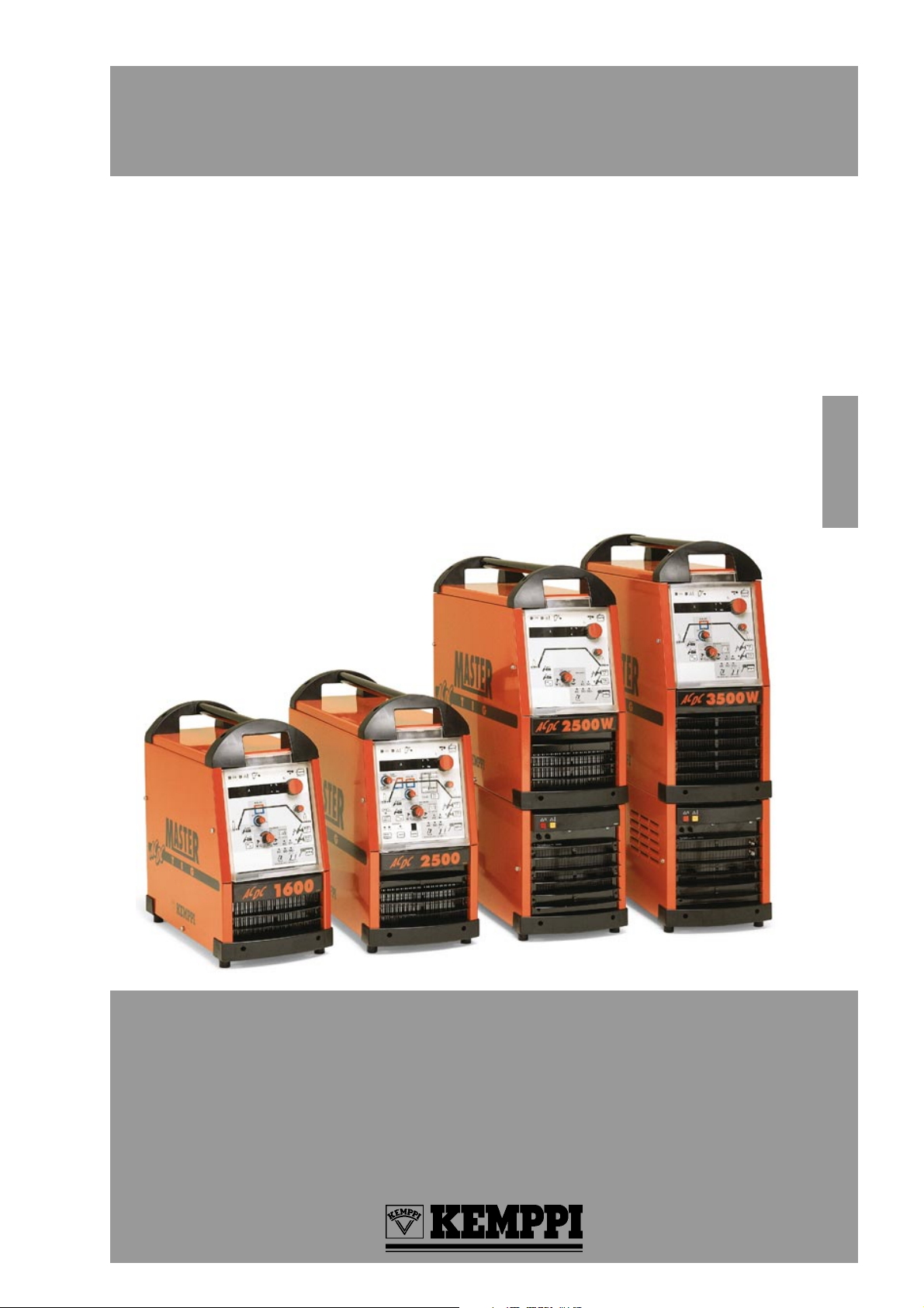
MASTERTIG AC/DC
MASTERTIG AC/DC
9901
Operation instructions
MASTERTIG AC/DC 1600 1~ 230 V
MASTERTIG AC/DC 2500 3~ 230 V / 400 V / 460 V
MASTERTIG AC/DC 2500W 3~ 230 V / 400 V / 460 V
MASTERTIG AC/DC 3500W 1~ 400 V
1916110E
English
Read carefully these instructions before you use the welding machine !
Bitte, lesen Sie diese Gebrauchsanweisungen vor Gebrauch der Schweiß-
maschine !
Lees deze gebruiksaanwijzing aandachtig door voor u de lasmachine in
gebruik neemt !
Veuillez lire et appliquer ces instructions avant utilisation de la machine!
Page 2

English
OPERATION SAFETY............................................. 3
TERMS OF GUARANTEE....................................... 3
1. GENERAL .......................................................... 4
2. INSTALLATION OF THE MACHINE ...................5
2.1 Cabling the machine ....................................5
2.2 Siting the machine ....................................... 7
2.3 Start of installation ....................................... 7
2.4 Connecting the machine to the mains supply .. 7
2.5 Cable for MMA welding and return
current cable ................................................ 8
2.6 The welding torch ........................................ 8
2.7 Electrodes to be welded ..............................8
2.8 TIG DC welding ........................................ 8
2.9 TIG AC welding ............................................8
2.10 Shielding gas ............................................. 9
2.11 Gas flow regulator ...................................... 9
3. OPERATING PANELS ...................................... 10
3.1 Numerical displays and signal lights
English
of the panel ............................................... 12
3.2 Use of the remote control .......................... 12
3.3 MMA welding ............................................. 12
3.4 TIG welding ............................................... 12
3.5 Memory functions
(only with the pulse panel) ......................... 16
3.6 Code locking .............................................. 16
4. COOLING UNIT
(only Mastertig AC/DC 2500W, -3500W) .......... 18
5. INTERNAL PROTECTIONS OF THE MACHINE.. 18
5.1 Overheating protection .............................. 18
5.2 Over-voltage protection of the mains
supply voltage ............................................ 18
5.3 The wrong voltage selection ...................... 18
5.4 Protection of a water-cooled torch ............. 18
6. MAINTENANCE ............................................... 18
6.1 The welding torch ...................................... 18
6.2 Cables ....................................................... 19
6.3 The power source ...................................... 19
6.4 Regular maintenance ................................19
7. OPERATION DISTURBANCES ........................ 19
8. ACCESSORIES................................................ 19
8.1 Remote control units.................................. 19
8.2 Wheel barrows and transport chassises ....20
9. EXTRA FUNCTIONS ........................................ 20
10. TECHNICAL DATA .........................................21
2 / 1916110E / 9901
Page 3

OPERATION SAFETY
Never watch the arc without a face shield designed for arc welding!
The arc damages unprotected eyes!
The arc burns unprotected skin!
Be careful for reflecting radiation of arc!
Protect yourself and the surroundings against the arc and hot spray!
Dont use power source for melting of frozen pipes!
Remember general fire safety!
Pay attention to the fire safety regulations. Welding is always classified as a fire risk operation.
Welding where there is flammable or explosive material is strictly forbidden.
If it is essential to weld in such an area remove inflammable material from the immediate vicinity of the
welding site.
Fire extinguishers must always be on site where welding is taking place.
Note! Sparks may cause fire many hours after completion of welding.
Watch out for the mains voltage!
Take care of the cables - the connection cable must not be compressed, touch sharp edges or hot work pieces.
Faulty cables are always a fire risk and highly dangerous.
Do not locate the welding machine on wet surfaces.
Do not take the welding machine inside the work piece (i.E. In containers, cars etc.)
Ensure that neither you nor gas bottles or electrical equipment are in contact with live wires or connections!
Do not use faulty welding cables.
Isolate yourself by using dry and not worn out protective clothes.
Do not weld on wet ground.
Do not place the TIG torch or the welding cables on the power source or other electrical equipment.
Be careful of TIG ignition pulse voltage!
Dont press on torch switch, if the torch is not directed towards work piece.
Dont use wet TIG torch. Do not use damaged TIG torch.
Watch out for the welding fumes!
Ensure that there is sufficient ventilation.
Follow special safety precautions when you weld metals which contain lead, cadmium, zinc, mercury or
beryllium.
Note the danger caused by special welding jobs!
Watch out for the fire and explosion danger when welding container type work pieces.
English
TERMS OF GUARANTEE
KEMPPI OY provides a guarantee for products manufactured and sold by them if defects in manufacture and
materials occur. Guarantee repairs must be carried out only an Authorized KEMPPI Service Agent. Packing,
freight and insurance costs to be paid by third party. The guarantee is effected on the day of purchase. Verbal
promises which do not comply with the terms of guarantee are not binding on guarantor
Limitations on guarantee
The following conditions are not covered under terms of guarantee: defects due to fair wear and tear, noncompliance with operating and maintenance instructions, connection to incorrect or faulty supply voltage (including voltage surges outside equipment spec.), incorrect gas pressure, overloading, transport or storage damage, fire or damage due to natural causes i.e. ligthning or flooding.
This guarantee does not cover direct or indirect travelling costs, daily allowances or accomodation.
Note: Under the terms of the guarantee, Welding torches and their consumables, feed, drive rollers and feeder
guide tubes are not covered.
Direct or indirect damage due to a defective product is not covered under the guarantee.
The guarantee is void if changes are made to the product without approval of the manufacturer, or if repairs are
carried out using non-approved spare parts. The guarantee is also void if repairs are carried out by non-authorised agents.
Guarantee period
The guarantee is valid for one year from date of purchase, provided that the machine is used for single-shift
operation. The guarantee period for double and treble shift operation is six months and four months respectively.
Undertaking guarantee repairs
Guarantee defects must be informed to KEMPPI or authorised KEMPPI Service Agents within the guarantee
period. Before any guarantee work is undertaken, the customer must provide proof of purchase and serial
number of the equipment in order to validate the guarantee. The parts replaced under the terms of the guarantee
remain the property of KEMPPI. Following the guarantee repair, the guarantee of the machine or equipment,
repaired or replaced, will be continued to the end of the original guarantee period.
9901 / 1916110E / 3
Page 4
1. GENERAL
Mastertig AC/DC is a power source for TIG /MMA welding suitable for AC and DC welding and designed
for demanding professional use. The power source is an inverter, which is formed with IGB transistors.
The power source is available in three sizes, 160 A, 250 A and 350 A. The 250 A power source comes in
two separate versions for gas-cooled torches and for water-cooled torches. Three different exchangeable panel versions are available for the power source: a basic panel, a MINILOG panel and a pulse panel.
ACDC panel
TTM 25W
ACDC minilog ACDC pulse
TTM 15
English
C 100AC
Equipment
Mastertig AC/DC 1600 ............................... 6161600
Mastertig AC/DC 2500 ............................... 6162500
Mastertig AC/DC 2500W ........................... 6162505
Mastertig AC/DC 3500W ........................... 6163505
ACDC panel................................................. 6162801
ACDC minilog .............................................. 6162802
ACDC pulse ................................................. 6162803
Accessories
T 120 transport unit .................................... 6185252
T 22 transport unit ...................................... 6185256
GH 20 (gun holder) ...................................... 6256020
TTM 22
GH 20
C 100F
TIG torches, gas-cooled
TTM 13 .......... 4 m .................................... 6271421
TTM 13 .......... 8 m .................................... 6271422
TTM 15 .......... 4 m .................................... 6271424
TTM 15 .......... 8 m .................................... 6271425
TTM 15 .......... 16 m .................................... 6271428
TTM 15S ....... 4 m .................................... 6271434
TTM 15S ....... 8 m .................................... 6271435
TTM 22 .......... 4 m .................................... 6271426
TTM 22 .......... 8 m .................................... 6271427
TTM 22 .......... 16 m .................................... 6271429
TTM 22S ....... 4 m .................................... 6271436
TTM 22S ....... 8 m .................................... 6271437
Remote control units
C 100C ........................................................ 6185410
C 100D ........................................................ 6185413
C 100AC ...................................................... 6185417
C 100F......................................................... 6185405
Cables
Extension cable for remote control ... 10 m ..... 6185456
Start extension cable C 100F......... 10 m ..... 6185310
Welding cables
Cable for MMA welding .. 25 mm
......................................25 mm
Cable for MMA welding .. 50 mm
......................................50 mm
Return current cable ....... 25 mm
......................................25 mm
Return current cable ....... 50 mm
......................................50 mm
4 / 1916110E / 9901
2
.. 5 m ..... 6184201
2
.. 10 m..... 6184202
2
5 m..... 6184501
..
2
.. 10 m..... 6184502
2
.. 5 m ..... 6184211
2
10 m..... 6184212
..
2
.. 5 m ..... 6184511
2
.. 10 m..... 6184512
TIG torches, water-cooled
TTM 20W ...... 4 m .................................... 6271511
TTM 20W ...... 8 m .................................... 6271512
TTM 25W ...... 4 m .................................... 6271521
TTM 25W ...... 8 m .................................... 6271522
TTM 25WS .... 4 m .................................... 6271531
TTM 25WS .... 8 m .................................... 6271532
TTM 35W ...... 4 m .................................... 6271541
TTM 35W ...... 8 m .................................... 6271542
= Warning
Page 5
2. INSTALLATION OF THE MACHINE
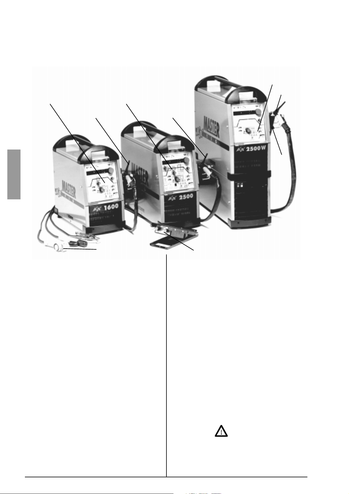
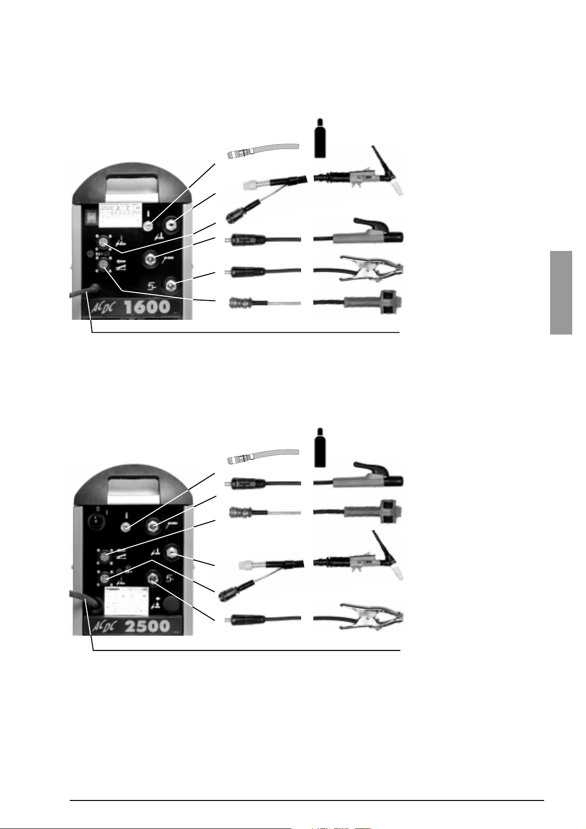
2.1 Cabling the machine
Mastertig AC/DC 1600
Shielding gas hose
Gas-cooled TIG torch
Cable for MMA welding
Return current cable
Remote control unit
English
Mains cable
Mastertig AC/DC 2500
Shielding gas hose
Cable for MMA welding
Remote control unit
Gas-cooled TIG torch
Return current cable
Mains cable
9901 / 1916110E / 5
Page 6
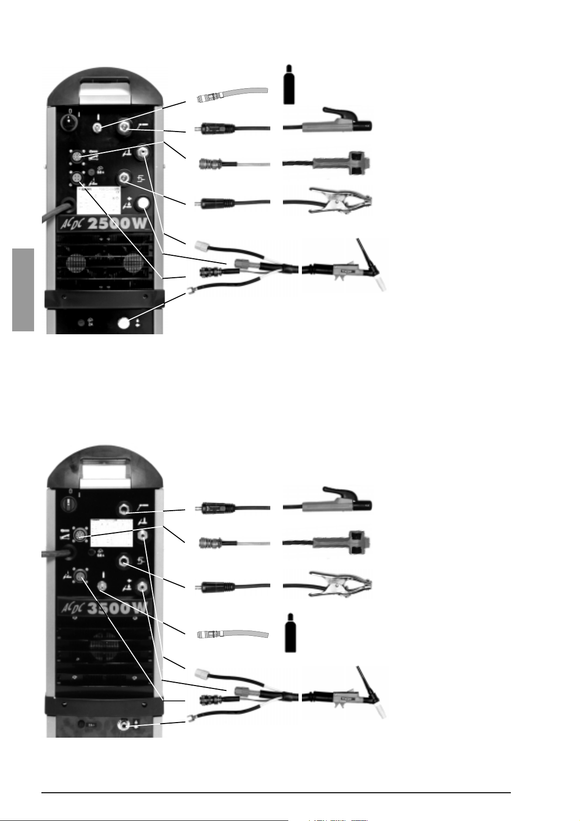
Mastertig AC/DC 2500W
English
Shielding gas hose
Cable for MMA welding
Remote control unit
Return current cable
Water-cooled TIG torch
Mastertig AC/DC 3500W
Cable for MMA welding
Remote control unit
Return current cable
Shielding gas hose
Water-cooled TIG torch
6 / 1916110E / 9901
Page 7
2.2 Siting the machine
When siting the machine, the following have to be
considered:
Site the machine on a fixed dry base, which does not
cause dust etc. into the suction air of cooling.
Make sure that the machine is placed away from
the line of particle spray from grinding tools.
Ensure the free circulation of the cooling air. Make
sure that there is at least a 20cm free distance
both in front of and at the rear of the machine for
the circulation of the cooling air.
Protect the machine against heavy rain and in hot
circumstances against direct sunshine.
2.3 Start of installation
2.4 Connecting the machine to the mains
supply
The installation or replacement of the mains
cable and the plug may be carried out only by
an authorized electric shop or electrician.
Mastertig AC/DC 1600
1600
The Machine is delivered with a mains cable with a
schuko plug for connection to a mains supply of 230 V.
To be noted when replacing the mains cable:
The lifting handles, cover and the right-hand-side plate
have to be opened. The cable in brought to the machine
through the inlet ring on the rear panel and fastened
with a cable clamp. The phase lead of the cable are
coupled to connector L, the blue to the connector of
the N lead and the yellow-green to the connector of
the protective grounding lead .
English
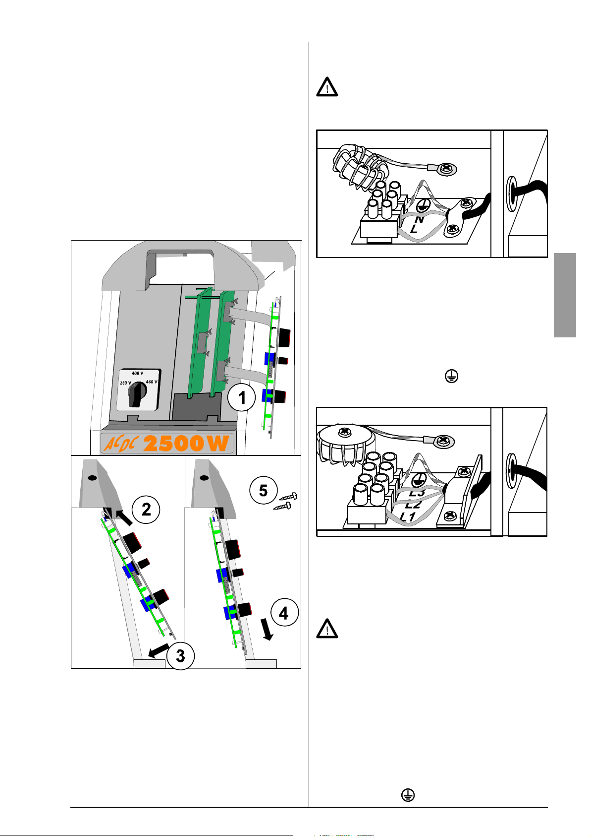
Mastertig AC/DC 2500 and -2500W: Check first that the
mains voltage change-over switch is in right position.
If it is needed to change mains cable, do it before
mounting to the wheel barrow T120. Otherwise you
bossibly have to dismount the machine.
Before connecting the machine to the mains supply,
one of the three panels, the ACDC panel, the ACDC
minilog or the ACDC pulse panel, has to be installed.
Installation instructions 4283280 are in the package of
the panel.
Mastertig AC/DC 2500, -2500W and -3500W
2500, 2500W, 3500W
The machine is delivered with a 5m mains cable
(4×2.5mm2) without a plug. Mains cable is suitable
for all mains voltages with recommended fuse size
(please look at Technical data table). 4×6mm2 cable
can be assembled to the machine, if local regulations
are requiring it.
If you use greater fuse size than recommended
big short circuit current can cause extra damage in case of failure.
Mastertig AC/DC 2500, -2500W
Before connecting the machine to the mains supply,
make sure that the voltage change-over switch of the
machine is turned to the position corresponding to the
mains supply voltage (230 / 400 / 460V).
When replacing the mains cable, note the following:
The lifting handles, cover and right-hand-side plate of
the machine have to be opened. The cable is brought
to the machine through the inlet right on the rear panel
and fastened with a cable clight. The phase leads of
the cable are coupled to connectors L1, L2 and L3; the
yellow-green is coupled to the connector of the protective grounding lead .
9901 / 1916110E / 7
Page 8

2.5 Cable for MMA welding and return
current cable
The welding cables have to be at least 16 mm2 copper
cables for Mastertig AC/DC 1600 and 25 mm2 copper
cables for Mastertig AC/DC 2500, Mastertig AC/DC
2500W and 50 mm2 copper cables for Mastertig AC/
DC 3500W. Thinner cables will cause voltage losses
and heating.
Connect the grounding clight of the return cable carefully, preferably directly to the piece to be welded. Use
as short welding cables as possible. Unnecessarily long
cables will lower the maximum output voltage of the
machine. Coiling of the excess cable lowers the output voltage of the machine especially in AC welding
and decreases the ignition spark.
Clean the fastening surface of any paint and rust!
Choice of the electrode for DC welding. The table is
only given as a guide.
Welding
current
range
Electrode
Gas nozzle
Gas
flow
rate
DC– WC20 Argon
A ø mm number ø mm l / min
5...80 1,0 4/5 6,5/8,0 5...6
70...140 1,6 4/5/6 6,5/8,0/9,5 6...7
140...230 2,4 6/7 9,5/11,0 7...8
225...350 3,2 7/8 11,0/12,5 8...10
330...350 4,0 10 16 10...12
2.6 The welding torch
In Mastertig AC/DC1600 and Masterig AC/DC2500,
only an gas-cooled torch can be used. In Mastertig AC/
DC 2500W and -3500W, you can use either an gascooled or a water-cooled torch. Make sure that the torch
English
you are using is designed for the maximum welding
current that you need.
Never use a damaged torch !
2.7 Electrodes to be welded
By the Mastertig AC/DC power sources you can use
all electrodes designed for DC or AC welding within
the current limits of the machine in question.
Mastertig AC/DC 2500, -2500W and -3500W power
sources is suitable for carbon arc gouging and cutting
according to its maximum power.
Reference max elecctrode diameters and yield
electrode type yield 1600
Fe-rutile 95 % ø 4 ø 5 ø 6
Fe-base 100 % ø 4 ø 5 ø 6
Fe-high-yield 180 %
Ss-rutile - - - ø 4 ø 6 ø 6
Ss-base - - - ø 4 ø 6 ø 6
Ss-high-yield 150 % ø 3,25 ø 5 ø 6
Hard facing by
welding
250-270 %
100 % ø 3,25 ø 5 ø 6
ø 2,5
- - -
2500,
2500W
ø 4
ø 4
2.8 TIG DC welding
DC current is used typically when welding different
kind of steel. We rekommend for DC welding a WC20
(grey) elctrode.
Sharpening of the electrode
The tip of the electrode is sharpened into a cone, so
that the arc becomes steady and the thermal energy is
concentrated on the spot being welded. The length of
the sharpening to the diameter of the electrode:
d
l
with small current sharp l = 3 x d
with large current blunt l = 1 x d
3500W
ø 5
ø 5
2.9 TIG AC welding
AC-current is typically used when welding aluminium.
We recommend for AC-welding a WC20 (grey) or a
clean wolfram electrode (green).
Balance
In AC-welding the ratio between the positive and negative half-cycle is called balance. With the balance you
can control heat between the electrode and work piece.
When balance is positive, it means that the positive
half-cycle is longer than the negative, more heat is
coming to the electrode than to the work piece. Correspondingly when balance is negative, negative halfcycles are longer, the work piece is hotter and the electrode is colder. Mastertig AC/DC-machines have buildin BALANCE-automatism, which chooses automatically
right balance value. User adjusts the BALANCE-knob
according to the electrode, and the machine takes care
of the balance control in different currents.
BALANCE automatics offers two benefits as compared to a constant balance:
In AC welding, you can use both a sharpened and
a rounded (cut) electrode. When welding starts,
the machine will round the cut tip so that its is suitable.
The current-range of the electrode is extended: the
current of the lower end is lowered and the current
of the maximum end is increased.
With BALANCE automatics, you can use the position
for a sharpened electrode with a
narrower arc to obtain a narrower
seam and to a deeper penetration
than with a rounded electrode. A narrow seam is useful especially in fillet
welding.
When using a rounded electrode, the arc is broad and
the cleaning area of the arc is also
wider, so it can be used for end-toend seams and outer corners.
8 / 1916110E / 9901
Page 9

The table is only given as a guide.
Welding current
range AC
min min max
A A A ø mm number ø mm l / min
15 25 90 1,6 4/5/6 6,5/8,0/9,5 6...7
20 30 150 2,4 6/7 9,5/11,0 7...8
30 45 200 3,2 7/8/10 11,0/12,5/16 8...10
40 60 350 4,0 10/11 16/17,5 10...12
Electrode
WC20 Argon
Gas nozzle
Gas
flow
rate
The table and the panel scale are based on the use of
WC20 (grey). When using pure wolfram electrode
(green) the tip rounds off slightly.
2.10 Shielding gas
Use as the shielding gas argon or other gas which is
suitable for TIG welding. The flow rate of the gas is
defined by the welding current and the size of the electrode. The table above shows the flow rate recommended.
Connect hose onto regulator and machine, tighten
jacket nuts.
Open valve of bottle slowly
Pressure meter (P1) shows pressure of bottle. Nev-
er use up all the gas in the bottle, send the bottle
for filling up when the bottle pressure still is 2 bar.
Open needle valve if there is one in regulator.
Screw regulation screw (2) inwards until hose pres-
sure meter (P2) shows flow (or pressure) required.
By regulation of flow amount the machine has to
be in operation and the gun switch should be
pressed on at the same time.
Close valve of bottle always after having stopped
welding
If the machine will be unused for a longer time, you
should also unscrew pressure regulation screw (2).
English
2.11 Gas flow regulator
Gas flow regulator should be suitable for shielding gas
used by you. The regulator being in your use might be
different from the one in picture, however, following general instructions are valid for all pressure regulators.
P1P2
51
53
55
54
56
57
Before mounting of flow regulator
Step aside, open cylinder valve (1) somewhat for a
moment, in this way you can blow out any dirt that
may be in the valve of bottle.
Screw the press regulation screw (2) of regulator
outwards so long that no spring pressure can be
felt (screw is turning freely).
Close needle valve (3) if there is one in regulator.
Connect regulator onto valve of bottle
Tighten connecting nut (4) preferably with a wrench.
Put hose spindle (5) of regulator with jacket nuts
(6) onto gas hose, connection should be ensured
with hose clamp (7).
52
56
9901 / 1916110E / 9
Page 10

3. OPERATING PANELS
BASIC
12
6
5
4
3
English
MINILOG
13
15
1
22
21
19
6
5
11
12
13
15
10 / 1916110E / 9901
4
3
2
1
22
21
21
19
Page 11

PULSE
10
79 8
ACDC
6
11
MINILOG
4
5
12
3
2
BALANCE
13
1
14
-9 ... 0 ... 9
15
3140530
3140050
16
1 Selection switches for TIG welding: TIG HF = spark TIG and TIG CONTACT = contact TIG
2 Frequency of AC welding,
3 Adjustment of post-gas time 0 ... 100 s
4 Adjustment potentiometer of the down-slope time of the welding current 0 ... 15 s
5 Current adjustment knob
6 Selection of local / remote control
CODE LOCK/ENTER
7 Adjustment of the pulse current of Pulse TIG PULSE 3 ... 160 A (250 A)
and the adjustment of the pulse ratio
8 Selection key of Pulse TIG
9 Adjustment of the background current of Pulse TIG
and adjustment of the frequency
10 Adjustment of the start current, starting with a current lower than the welding current
START, or with a current higher than the welding current HOT START -70 ... +50 %
11 Selection of Minilog operations and adjustment of the current level
12 Adjustment of the pre-gas time, and at the same time the key for code locking
13 Adjustment of the up-slope time of the welding current 0 ... 5 s
14 Selection of fusion spot welding and adjustment of time,
15 Selection of the operation mode of the torch switch
16 Calling the welding parameters from the memory or from the panel
17 Saving the welding values in the memory
18 Selection key of the memory channel
19 Selection key for broken-arc method
20 Adjustment of the dynamics (arc force) of MMA welding
21 Selection key of MMA welding
22 Adjustment potentiometer of the form of the AC TIG arc BALANCE -70 ... +70 %
17
FREQUENCY 50 ... 200 Hz
I
, used also to adjust the values of the parameters with keys.
2
REMOTE and at the same time the key for code locking
RATIO 10 ... 75 %
FREQUENCY 0.1 ... 300 Hz
SAVE.
CHANNEL 1 ... 9
BROKEN ARC.
MMA
2018 19
BACK 20 ... 40 %
MINILOG -80 ... +20 %
SPOT WELD 0 ... 10 s
2T / 4T.
MEM. / PANEL.
DYNAMICS -9 ... 9
22
21
SOFT
CODE LOCK.
English
9901 / 1916110E / 11
Page 12

kuvat 11 - 15
3.1 Numerical displays and signal lights
of the panel
Machine on
Display of welding
current or set value current
The signal light of thermal protection is on when the
machine has over-heated. Let the machine on so that
the fan will cool the machine. Wait until the light goes
off, and you can continue welding.
The light for the wrong voltage turns on if the mains
English
voltage is too high or too low. Check the voltage setting of the machine and/or the mains voltage. The wrong
voltage light will also turn on if there is a momentaneous over-voltage in the mains supply.
The current is displayed with a tolerance of 3 % ± 2 A;
the voltage with a tolerance of 3 % ± 0.2 V.
Heat protection
Display of
welding voltage
or parameters
Wrong mains
voltage, over or
under-voltage
Units of the
display
3.2 Use of the remote control
Broken arc method
Press the BROKEN ARC key and the signal light for
broken arc method turns on.
A broken arc method has to be used if the seam to be
welded cannot tolerate the heat of a continuous arc.
The heat of the welding is controlled by breaking the
arc. Usually the reason is thin material or various fittings. In the broken arc method position, the arc breaks
faster and the ignition pulse is smaller then in ordinary
MMA welding.
Control of MMA welding dynamics (only with
minilog and pulse panels)
-9 ... 0 ... 9
DYNAMICS
Press the DYNAMICS key and you will see the numerical value corresponding to the dynamics in the display. You can change the value by turning the current
knob. Numerical value zero is the normal setting for all
MMA electrodes. When the value is adjusted negative
(-1...9), the arc is softened. The amount of spatter
decreases when welding at the upper end of the recommended current range of the electrode. On the positive side (1...9) the arc is rough. It is suitable e.g. for
thin stainless steel rods when welding near the lower
end of the recommended current range.
3.4 TIG welding
The remote control is selected from the key REMOTE.
With the remote control you can adjust the welding
current of MMA and TIG welding. The values of the
parameters (up-slope and down-slope times, gas flow
times etc.) are adjusted from the current knob.
With remote control unit C100AC you can also change
the welding method (MMA / TIG). The machine selects
the polarity (type of current) in accordance with an advance selection on the panel.
3.3 MMA welding
Selection of type of current
Select MMA welding by pressing the selection key of
MMA welding. The signal light of the type of current
indicates the current type selected: AC, DC-, DC+.
Change the current type by pressing the MMA selection key again and the current type will change and the
signal light will show the current type selected.
12 / 1916110E / 9901
Selection of TIG welding and type of current
TIG
HF
TIG
AC
Press the selection key next to the selected TIG method, spark TIG (TIG HF) or contact TIG (TIG CONTACT),
and the signal light next to the key will show the method.
You can change the type of current by pressing the selection key again. (If you want to select DC+ as the current type for TIG, press both TIG keys at the same time.)
Spark ignition
Use contact ignition when you are welding in a
environment where are sensitive electronic
equipements. The ignition spark can cause interferences in equipements near the welding machine.
The arc is ignited with a high-frequency, high-voltage
spark without touching the work piece. If the arc is not
ignited in spite of the spark within one second, you will
have to try the ignition again by pressing the torch
switch. In some cases the spark ignition works better if
you touch the work piece with the gas nozzle lightly
before the ignition.
DC-
CONTACT
Page 13

kuvat 16 - 23
Contact ignition
2134
Press the electrode lightly against the work piece (1).
Press the switch and the shielding gas will start to flow
and a small current will pass through the electrode. Lift
the electrode away from the work piece by turning it so
that gas nozzle rests against the work piece (2 ja 3),
and the arc will ignite and the current will rise to the
welding level within the up-slope time (4).
Use and selection of operation of the torch
switch
4T
2T
4. Release the torch switch, and the welding current
will drop in accordance with the selected downslope time. After the arc is turned off, the shielding
gas will continue to flow for the post-gas time.
2
The down-slope time of the welding current can be interrupted by quickly pressing the torch switch.
2
You can go back to the welding current from the downslope current by pressing the torch switch down. After
that, the current will rise at a rate corresponding to the
down-slope time.
4-function (4T) / spark ignition
English
4T
/
2T
The operation of the torch switch is selected by pressing the 2T/4T key.
2-function (2T) / spark ignition
2
1. Press the torch switch. The gas starts to flow and
after the pre-gas time selected, the arc is ignited
and the current rises to the welding level within the
selected up-slope time.
2. Release the torch switch, and the welding current
will drop in accordance with the selected downslope time. After the arc is turned off, the gas will
continue to flow for the post-gas time.
2-function (2T) / contact ignition
21
2
2413
1. Press the torch switch down. The shielding gas
starts to flow.
2. Release the torch switch. The ignition spark ignites
the arc and the current will rise to the welding level
within the up-slope time.
3. Press the torch switch down. The welding continues.
4. Release the torch switch, and the current starts to
drop and after the selected down-slope time the
arc is broken. After this, the shielding gas will flow
for the time selected.
4-function (4T) / contact ignition
3
241
2
1. Press the tip of the torch lightly against the work piece.
2. Press down the torch switch.
3. Lift the electrode slowly away from the work piece.
The arc will ignite and the welding current will rise
to the welding level within the selected up-slope
time.
2
13
2
1. Press the electrode lightly against the work piece.
2. Press the torch switch down for a moment.
3. Lift the electrode slowly away from the work piece.
The arc will ignite and the welding current will rise
to the welding level within the up-slope time.
4. Press the torch switch down. The welding continues.
5. Release the torch switch, and the welding current
will drop and stop after the selected down-slope
time. After the arc is turned off, the shielding gas
will continue to flow for the post-gas time.
4
5
9901 / 1916110E / 13
Page 14

kuvat 24 - 31
2
By pressing the torch switch during the down-slope time
of the current, the current will remain at that level as
long as the switch is pressed down. After the release
of the switch, the current will drop further.
Adjustment of the form of the arc, BALANCE
The BALANCE function will adjust the balance so that
it is suitable for the selected electrode and current. At
the same time, it adjusts the pre-heating of the tip of
the electrode at the start in accordance with the tip
form selected.
2.4
3.2
BALANCE
4.0
2
By pressing the switch down for a moment, you can
raise the welding current back to the welding level.
Adjustment of the down-slope time of the
welding current
English
15 s
The adjustment of the down-slope time is done from
the potentiometer. The time can be adjusted between
0-15 s. When you adjust the down-slope time, you
can see the time in seconds in the right-hand numerical display. After 5 seconds, the display will return to
the start status.
Adjustment of the up-slope time of the welding current
AC
1a. When welding with a sharpened electrode, turn the
control knob to the left edge of the range of the
electrode that you have selected. (Narrow arc, deep
penetration, range: small seams)
1b. When welding with a rounded electrode, turn the
control knob to the right edge of the range of the
electrode that you have selected.
2. If you want more heat to the electrode, turn the knob
to the right, or if you want less heat, turn it to the left.
Frequency adjustment of TIG AC welding (only
with minilog and pulse panel)
The frequency of AC welding can be adjusted by means
of the MINILOG and PULSE PANEL. Raising the frequency will make the arc slightly more stable and narrow, but it will increase the noise caused by arc.
FREQUENCY
50 - 200 Hz
AC
1. Press the FREQUENCY key in the AC square.
2. Adjust the frequency with the current knob. The
adjustment range of the frequency is 50...200Hz.
When leaving the factory, the frequency of the
machine is 60Hz.
CODE LOCK
1. Press the key next to the up-slope of the current
pattern. The right-hand numerical display will show
the up-slope time in seconds.
2. Select the desired value by turning the current knob
(0-5s). 5 seconds after the adjustment, the displays will return to show the set value of the current.
Adjustment of the pre-gas and post-gas times
1. Press the switch in the panel next to the gas bottle
of the current model of either the pre-gas or the
post-gas.
2. Turn the current knob until the value that you want
is shown in the right-hand display. (Pre-gas 0-5s,
post-gas 0-100s)
14 / 1916110E / 9901
Minilog operation (only with minilog and pulse
panel)
MINILOG
OFF
+20%
-80%
With the Minilog operation you can select two currency levels, the welding current and the base current,
and you can move from one to the other by quickly
pressing the torch. The Minilog operation can be used
only with a 4-function torch switch operation.
Page 15

kuvat 32 - 37
The selection and adjustment of the Minilog operation
is done by means of the potentiometer. When the potentiometer is in the OFF position, the operation is not in
use. The welding current is selected from the current
knob like usually. The Minilog knob is used to select a
basic current, the minimum of which is 80% below the
welding current and the maximum is 20% above the
current level. During the adjustment, you can see the
set value of current in amperes in the current display.
2
You can move from the welding current to the basic
current by quickly pressing the torch.
By quickly pressing it again, you move back to the
welding current. The signal lights on the panel show
you the current level you are on.
You can stop the welding by a longer pressing of the
torch switch (>0.7 s).
The Minilog operation can be used to adjust the heat,
if the work piece is overheated or if you need more
heat for a moment.
With the Minilog operation you can go to a lower current level for example when you change the position or
the grip of the filler material wire without having to stop
the welding to do that.
A lower current can also be used as the crater filling
current if you do not want to use the down-slope time
for that.
Pulse welding (only with the pulse panel)
PULSE
RATIO
BACK.
pulse current, but please note that this will change
the average current.
6. When you press the key PULSE RATIO again, you
can adjust the pulse ratio, rAt. The pulse ratio is shown
as a percentage of the total length of the cycle.
7. When you press either of the parameter keys a
third time, the adjustment goes back to the average current AvE.
Control of the start current (only with the pulse
panel)
OFF
SOFT
START
By means of the control potentiometer of the start current you can select either a soft, normal or hot start.
The start current is available only with a 4-function torch
switch operation.
By turning the potentiometer to OFF, you have a normal start (see the use of the torch switch / 4-function)
By turning the potentiometer to the left, you get a soft
start (SOFT START). When you raise the torch switch,
the current rises in accordance with the up-slope of
the start current to the start current, which is smaller
than the welding current.
From the start current, you can move to the welding current by pressing the torch switch for a short moment.
The start current is proportional to the welding current.
You can see the value of the start current in the numerical display during the control.
HOT
START
+50%
-70%
2
English
FREQUENCY
ON /
PULSE
1. Switch the pulse welding on by means of the pulsesection key ON/OFF.
2. Adjust the average current that you want from the
current adjustment knob. The current display will
show you the average current.
3. Press the key BACK. FREQUENCY once. The text
bAc of the right-hand display shows you that now
you can adjust the background current from the
current knob. The background current is proportional to the average current, but it is shown in the
current display in amperes.
4. Press the key BACK. FREQUENCY again. The text
FrE of the current display shows that now you can
adjust the pulse frequency. The pulse frequency is
shown in Hz.
5. Press the key PULSE RATIO once. You will see
the pulse current in the current display. The righthand display reads PUL. You can also adjust the
OFF
2
When you turn the potentiometer to the right, the start
current is higher than the welding current (HOT
START). Otherwise the start is made in the same way
as with a soft start.
Fusion spot welding (only with a pulse panel)
0 - 10 s
SPOT
WELD
Select fusion spot welding by pressing the special operation key SPOT WELD. To show that you have selected fusion spot welding, the signal light next to the
9901 / 1916110E / 15
Page 16

kuvat 38 - 48
key goes on. You can select the spot time that you
want with the current knob. The time selected is shown
in the numerical display during the adjustment. Five
seconds after the adjustment, the display returns to
the set value of the current and you can adjust the
welding current.
The time shown in the display means the time you have
the welding current. The down-slope and the up-slope
times are increasing the burning time of the arc.
3.5 Memory functions (only with the pulse
panel)
By means of the memory functions you can save 9
panel settings in the permanent memory. All adjusta-
English
ble or chooseen values are saved in the memory. When
the memory function is not in use, the numerical display of the memory section is black.
With the CHANNEL key you can select the channel to
be read and used for the saving of a setting.
The MEM / PANEL key is used to select whether to
use the values in the memory or values controlled from
the panel.
The function of the SAVE key is two-phased. When
you press it once, you select the values to be saved. In
this case the light SAVING is blinking to show that you
are performing a saving operation. When the light is
blinking, you can find the channel into which you want
to save the values. When you press the key again, the
information is saved in the memory.
Calling the values from the memory.
1. Press the CHANNEL key so many times that the
numerical channel display shows the number of
the channel that you want. At the same time, the
signal lights of the panel show you the selections
of the selected channel and the current display
shows you the set value of the current. You can
see the other values of the welding parameters by
pressing the parameter key or by turning the potentiometer. All the values are locked, which means
that you cannot change them while the MEM signal light is on.
Saving a welding situation (parameters) in the
memory.
You have good welding values, which you want to save
in the memory.
1. Press the SAVE key once and the SAVING light
starts to blink.
PANEL
SAVINGMEM.
2. Press the CHANNEL key so many times that the
number of the channel in which you want to save
the values is shown in the numerical display.
PANEL
SAVINGMEM.
3. Now press the SAVE key again and the values are
saved in the memory.
PANEL
SAVINGMEM.
Note! When you are saving (= the SAVING light is blinking) and you have rolled the number of the channel
that you want by using the CHANNEL key, you can see
the previous values of that channel by pressing the
MEM / PANEL key to bring the panel to the MEM status, so that you can check the present values of that
channel. In this case the values to be saved will not
change. After the check, press the MEM / PANEL key
again and you can again see the values to be saved
and you can save them by pressing SAVE.
3.6 Code locking
The welding machine has a theft protection. You can
install a three-digit machine-specific code into the machine, which the user must know in order to turn the
machine on. The code is saved in the panel. If you
change the panel the code is follows the panel.
When the machine leaves the factory, the code locking operation is not on.
Installing the code locking
1. Press the pre-gas key (CODE LOCK) and the key
of the remote control (REMOTE / CODE LOCK/
ENTER) at the same time.
PANEL
SAVINGMEM.
2. If you want to change the values found, press the
MEM / PANEL key and the PANEL signal light
comes on and you can change the values.
PANEL
SAVINGMEM.
16 / 1916110E / 9901
2. Select the first digit from the current adjustment
knob (e.g. 4).
3. Press the accept key (REMOTE / CODE LOCK/
ENTER).
Page 17

kuvat 49 - 52
4. Select the second digit from the knob (e.g. 3) and
again accept it by pressing the key (REMOTE /
CODE LOCK/ENTER).
5. Select the third digit in the same way (e.g.2).
Now the code locking is on with the number that
you have chosen (e.g. 432).
Turning the machine on when the code locking is on
When you turn on a machine in which the code locking
is on, you must always feed in the opening code that
you have installed in order to be able to use the machine.
3. Turn the machine off. The machine is now ready
for use.
Changing the code
1. Remove the code locking in accordance with the
above instruction.
2. Install the code locking again.
English
1. Feed in the first digit from the current adjustment
knob.
2. Accept the digit by pressing (REMOTE / CODE
LOCK/ENTER).
3. Feed in the second and third digits in the same
way.
The machine is ready for use.
If you enter wrong code, you can try again by
turning the machine off and on. If you can not
open the machine, you do not remember the right
code, contact an authorized service agent.
Removal of code locking
1. Press the key for pre-gas (CODE LOCK) and the
key for remote control (REMOTE / CODE LOCK/
ENTER) at the same time.
2. Feed in the digits of the code in the same way as
when opening the machine. The code locking will
be removed after you have fed in the last digit.
9901 / 1916110E / 17
Page 18

kuvat 53 - 54
4. COOLING UNIT
(only Mastertig AC/DC 2500W, -3500W)
P
e
English
no
pressure
overheated
liquid
diately turned off. If the over-voltages are short in duration, this may be seen as short breaks in the current.
The signal light of the panel showing an over / undervoltage comes on during a long period of over-voltage.
5.3 The wrong voltage selection
Mastertig ACDC 2500, Mastertig ACDC 2500W
If a multi-voltage machine is connected
to the wrong voltage, the machine will not
start and the signal light in the front panel comes on to indicate this. The machine
will not be damaged if it is connected to
the wrong voltage for a short time. Unplug the machine
from the mains supply and select the correct voltage
from the switch under the front panel.
5.4 Protection of a water-cooled torch
Mastertig ACDC 2500W and -3500W
If the switch of the cooling unit is in the position for an
gas-cooled torch and you start welding with a watercooled torch and a current is over 60 A, the welding is
broken.
gas- / water-cooled
torch GAS / WATER
Filling in the liquid and checking the liquid level is done
by pulling open the hatch in the lower part of the machine so that you can see the filling hole for the liquid.
The cooling units tank is filled with 2040% glycol/
water mixture according to antifreeze requirements.
Instead of glycol/water mixture you can also use another liquid according to your experience.
The circulation of the liquid is operation-controlled,
which means that the liquid is circulating only during
welding and for a while after the welding.
test run of the circulation
of the liquid TEST
5. INTERNAL PROTECTIONS OF
THE MACHINE
5.1 Overheating protection
The yellow signal light of the overheating
protection comes on and the machine
stops when the machine has overheated. The machine
may overheat if the machine is loaded for a long time
with a current higher than 100 % of the duty cycle or
when the circulation of the cooling air is prevented.
5.2 Over-voltage protection of the mains
supply voltage
If the over-voltages in the mains supply are
so high that they can endanger the ma-
chine, the supply of the machine is imme-
6. MAINTENANCE
The amount of use and an unusual working environment have a special effect on the need for maintenance.
Proper use and preventive maintenance will help to
ensure trouble-free operation of the machine without
unexpected interruptions.
6.1 The welding torch
Due to high temperatures and wear, the welding end
of the TIG torch requires maintenance most, but also
the condition of the other parts should be checked regularly.
The welding end
Check that...
all insulations of the welding end are undamaged
and in place.
the gas nozzle is undamaged and suitable for the
work.
the flow of the shielding gas is free and even.
the electrode is undamaged. Use an electrode size
and tip sharpening which are suitable for the weld-
ing job. Sharpen the electrode lengthwise.
the fastening parts of the electrode are undamaged
and that the electrode is tightly fastened in its place.
The torch cable
Check that...
the insulation of the handle and the torch cable is
undamaged.
the torch cable has not sharp bends.
Always replace any damaged parts immediately!
Follow the instructions of the torch manufacturer in all
maintenance and repair measures.
18 / 1916110E / 9901
Page 19

6.2 Cables
Check the condition of the welding and connection
cables daily. Do not use damaged cables!
Check also that the mains connection cables that you
use are in good condition and that they comply with all
the regulations!
Mains connection cables may be repaired and installed
only by an authorized electric shop or electrician.
6.3 The power source
NOTE! Disconnect the plug of the machine from the
mains socket and wait for ca. 2 minutes (capacitor
charge) before removing the casing plate.
Check at least very six months:
The electric connections of the machine clean any
oxidized parts and tighten any loose ones.
NOTE! You must know the correct tension torques
before you start to repair the connections.
Clean the inner parts of the machine from dust and
dirt e.g. with a soft brush and a vacuum-cleaner.
Do not use pressurized air, because there is the
danger that the dirt is packed even more tightly in
the gaps of the cooling profiles. Do not use a pres-
sure washing device.
Only an authorized electric shop or electrician may repair the machine.
C 100C
Control of MMA / TIG welding current, memory scale
1 - 10.
C 100D
Control and fine-tuning of MMA / TIG welding current,
memory scale 1 - 10.
C 100AC
Control of MMA / TIG welding current, memory scale
1 - 10 and MMA / TIG selection.
C 100F
Foot pedal control unit for TIG welding
start function
adjustment of the welding current with pedal move-
ments
limitation of the welding-current range with min and
max potentiometers
English
6.4 Regular maintenance
KEMPPI Service Repair Shops handle regular maintenance by agreement.
Regular maintenance includes e.g. the following:
Cleaning of the machine.
Checking and maintenance of the welding tools.
Checking the clamps, switches and potentiome-
ters.
Checking the electric connections.
Checking the mains cable and plug.
Replacement of any parts that are damaged or in
poor condition.
Maintenance testing. The operation and perform-
ance values of the machine are checked and,
where necessary, adjusted by means of test equip-
ment.
7. OPERATION DISTURBANCES
In the case of operation disturbances, contact an authorized KEMPPI Service Repair Shop.
Check the maintenance parts before sending the machine to the service shop.
Connecting the foot pedal unit:
The foot pedal unit has two connections, which are
connected to the remote control and start connections
in the rear of the power source. When using the foot
pedal unit, the maximum current output of the machine
is ca. 30 % below its maximum output unless the machine is calibrated for the foot pedal unit.
Calibration of the machine for the foot pedal unit:
1. Turn the machine off.
2. Press the REMOTE key and at the same time turn
the machine on; the display will show the text rEn 01.
3. Turn the current adjustment knob so that the display will show rEn02. (01=C 100C, 02=C 100F)
4. Press the REMOTE key so that the setting is saved
in the memory.
8. ACCESSORIES
8.1 Remote control units
C 100C C 100D
C 100AC
9901 / 1916110E / 19
Page 20

8.2 Wheel barrows and transport chassises
T 120 (transport unit)
Mastertig AC/DC 1600, 2500, 2500W, 3500W
lifting ear
Do not lift the
welding machine
and the transport
unit with a gas
bottle.
English
T 22 (transport unit)
Mastertig AC/DC 2500,
2500W, 3500W
post gas button. All jumper settings are then saved
in the memory.
Jumper functions are:
(Factory settings are underlined)
J01: [On] = slope of up slope is constant, up slope time
depends on set value of current.
Off = up slope time is independed of set value
of current.
J02: [On] = slope of down slope is constant, down
slope time depends on set value of current.
Off = down slope time is independed of set value of current.
J03: On = TIG antifreeze is on.
[Off] = TIG antifreeze is not in use.
J04: [On] = manual AC balance control.
Off = balance function in use.
J05: [On] = tag welding automatics on.
Off = tag welding automatics is not in use.
J06: [On] = down slope falls to minimum end level cur-
rent (3 A DC, 10 A AC)
Off = down slope falls down to end level which
is 20 % of the welding current
J07: [On] = open-circuit voltage is 39 V
Off = open-circuit voltage is 70 V
J08: [On] = when stopping welding with 4T function
the down slope starts by pressing torch connector. Slope continues as long as you press the connector. Current stays at end level in case you press
longer than down slope´s normal time (look J06).
Off = 4T function is as it has been described on
the operation instructions.
J09 ... J15 Not in use.
J16: Length of positive start cycle of AC-TIG 0.0...2.0,
factory setting is 1.
J17: Adjustment of MMA ignition pulse 0.0...2.0, fac-
tory setting is 1.
lifting ears
on the both sides (total 4 pcs)
9. EXTRA FUNCTIONS
There is extra functions and selections in the machine,
which are not seen in the panel. The welder needs these functions not in normal welding, but they may be a
solution in some special cases. These function are called jumper-functions, because they are behind jumper
numbers. Function can be On/Off -type or adjustable
parameter.
Jumper functions are used as follows:
1. Turn off the machine.
2. Press the post gas button and in the same time
turn the machine on. You can see text (SE.1 000)
on the panel.
3. Press once the pre gas button. Now text (J01 OFF)
or (J01 On) is on te panel.
4. Choose jumper number, which you want by pressing REMOTE button.
5. Change setting of the jumper with current knob I2.
6. When you have done all changes press once the
20 / 1916110E / 9901
Page 21

Technical data Mastertig AC/DC 1600
Mains voltage 1~ 50 / 60 Hz 230 V ± 10 %
Rated power TIG 25 % ED
TIG 100 % ED
MMA 15 % ED
MMA 100 % ED
Connection cable 3 x 1,5 mm2 S - 3 m
Fuse 16 A slow
Welding current range TIG DC
AC
MMA DC
AC
Maximum load **) TIG AC 50 % ED (T = 40 °C)
TIG AC 100 % ED (T = 40 °C)
MMA 15 % ED (T = 40 °C)
MMA 100 % ED (T = 40 °C)
TIG AC 60 % ED (T = 20 °C)
TIG AC 100 % ED (T = 20 °C)
MMA 15 % ED (T = 20 °C)
MMA 100 % ED (T = 20 °C)
Open circuit voltage (AC and DC) 70 V DC
Frequency of AC fixed / adjustable *) 60 Hz / 50 ... 200 Hz
Efficiency 75 % (160 A / 26 V)
Power factor 0,8 (160 A / 26 V)
Open circuit power 18 W
Storage temperature range -40 ... +60 °C
Operating temperature range -20 ... +40 °C
Temperature class / Degree of protection B (130 °C), H (180 °C) / IP 23C
External dimensions length, width, height 540 mm, 260 mm, 510 mm
Weight 28 kg
160 A / 4,7 kVA
90 A / 2,3 kVA
160 A / 6,8 kVA
90 A / 3,5 kVA
3 A / 10 V ... 160 A / 16,4 V
10 A / 10 V ... 160 A / 16,4 V
10 A / 20 V ... 160 A / 26,4 V
10 A / 20 V ... 160 A / 26,4 V
160 A / 16,4 V
120 A / 14,8 V
160 A / 26,4 V
90 A / 23,6 V
160 A / 16,4 V
135 A / 14,8 V
160 A / 26,4 V
100 A / 24 V
English
Technical data Mastertig AC/DC 2500 2500W 3500W
Mains voltage 3~ 50 / 60 Hz 230 V ± 10 %
Rated power (U1=400V) TIG 70 % ED
Connection cable 4 x 2,5 mm2 S - 5 m
Fuse 230 V
Welding current range
Maximum load (T=40 °C) TIG AC 60 % ED
Maximum load (T=20 °C)
Open circuit voltage (AC and DC) 70 V DC
Frequency of AC fixed / adjustable *) 60 Hz / 50 ... 200 Hz
Efficiency 80 % (250 A / 30 V) 80 % (350 A / 34 V)
Power factor 0,9 (250 A / 30 V) 0,9 (350 A / 34 V)
Open circuit power 18 W
Storage temperature range -40 ... +60 °C
Operating temperature range -20 ... +40 °C
Temperature class / Degree of protection B (130 °C), H (180 °C) / IP 23C
External dimensions
Weight 39 kg 65 kg 74 kg
Max liquid pressure of cooling unit – – – – 350 kPa 350 kPa
Rated power of cooling unit – – – – 1300 W 1300 W
TIG 100 % ED
MMA 40 % ED
MMA 60 % ED
MMA 100 % ED
400 V
460 V
TIG DC
AC
MMA 10 A / 20 V ... 250 A / 30 V 10 A / 20 V ... 350 A / 34 V
70 % ED
100 % ED
MMA DC 40 % ED
60 % ED
100 % ED
TIG AC 100 % ED 250 A / 20 V 310 A / 22,4 V
MMA DC 80 % ED
100 % ED
length
width
height
400 V ± 10 %
460 V ± 10 %
250 A / 7,5 kVA
200 A / 6,7 kVA
250 A / 10,3 kVA
– – – –
200 A / 7,9 kVA
20 A slow
16 A slow
16 A slow
3 A / 10 V ... 250 A / 20 V
10 A / 10 V ... 250 A / 20 V
– –
250 A / 20 V
220 A / 18,8 V
250 A / 30 V
– –
200 A / 28V
250 A / 30 V
240 A / 29,6 V
690 mm
260 mm
550 mm
690 mm
260 mm
830 mm
3 A / 10 V ... 350 A / 24 V
10 A / 10 V ... 350 A / 24 V
– – – –
400 V ± 10 %
– – – –
350 A / 11,7 kVA
320 A / 9,3 kVA
– – – –
350 A / 15,7 kVA
280 A / 11,2 kVA
– – – –
20 A slow
– – – –
350 A / 24 V
– –
280 A / 21,2 V
– –
350 A / 34 V
280 A / 31,2 V
350 A / 34 V
300 A / 32 V
690 mm
260 mm
870 mm
*) Adjustable with MINILOG- and PULSE panels.
**) Fuse can reduce maximum load.
The products meet conformity requirements for CE marking.
9901 / 1916110E / 21
 Loading...