

Page 1
Mastertig
aC/DC 2000, 2500, 2500W, 3500W
1916200E
0701
Page 2

2 – Mastertig aC/DC 2000, 2500, 2500W, 3500W/0701 © keMppi oy
CONTENTS
1. PREFACE ........................................................................................................................ 3
1.1. Introduction .......................................................................................................................3
1.2. Product introduction ..........................................................................................................
3
1.3. Operation safety ................................................................................................................
4
2. INSTALLATION ............................................................................................................... 5
2.1. Cabling the machine .........................................................................................................5
2.2. Siting the machine .............................................................................................................
7
2.3. Start of installation .............................................................................................................
7
2.4. Connecting the machine to the mains supply ...................................................................
8
2.5. Cable for MMA welding and return current cable ..............................................................
9
2.6. The welding torch ..............................................................................................................
9
2.7. Electrodes to be welded ....................................................................................................
9
2.8. TIG DC welding .................................................................................................................
9
2.8.1. Sharpening of the electrode ............................................................................................ 9
2.9. TIG AC welding ...............................................................................................................10
2.9.1. Balance .........................................................................................................................10
2.10. Shield gas ....................................................................................................................... 11
2.10.1. Installing gas bottle ....................................................................................................... 11
3. OPERATING PANELS ..................................................................................................12
3.1. Numerical displays and signal lights of the panel ...........................................................14
3.2. Use of the remote control ................................................................................................
14
3.3. MMA welding ...................................................................................................................
14
3.3.1. Selection of type of current ........................................................................................... 14
3.3.2. Broken arc method ........................................................................................................
14
3.3.3. Control of MMA welding dynamics (only with minilog and pulse panels) ......................
15
3.4. TIG welding .....................................................................................................................15
3.4.1. Selection of TIG welding and type of current ................................................................ 15
3.4.2. Spark ignition ................................................................................................................
15
3.4.3. Contact ignition .............................................................................................................
15
3.4.4. Use and selection of operation of the torch switch ........................................................
16
3.4.5. Adjustment of the down-slope time of the welding current ............................................
17
3.4.6. Adjustment of the up-slope time of the welding current ................................................
17
3.4.7. Adjustment of the pre-gas and post-gas times ..............................................................
17
3.4.8. Adjustment of the form of the arc, BALANCE ...............................................................
17
3.4.9. Frequency adjustment of TIG AC welding (only with minilog and pulse panel) ............
18
3.4.10. Minilog operation (only with minilog and pulse panel) ...................................................
18
3.4.11. Pulse welding (only with the pulse panel) .....................................................................
19
3.4.12. Control of the start current (only with the pulse panel) ..................................................
19
3.4.13. Fusion spot welding (only with a pulse panel) ...............................................................
19
3.5. Memory functions (only with the pulse panel) .................................................................20
3.5.1. Calling the values from the memory .............................................................................. 20
3.5.2. Saving a welding situation (parameters) in the memory ...............................................
20
3.6. Code locking ...................................................................................................................20
3.6.1. Installing the code locking ............................................................................................. 21
3.6.2. Turning the machine on when the code locking is on ...................................................
21
3.6.3. Removal of code locking ...............................................................................................
21
3.6.4. Changing the code ........................................................................................................
21
4. COOLING UNIT (ONLY MASTERTIG AC/DC 2500W, -3500W) .................................. 22
5. INTERNAL PROTECTIONS OF THE MACHINE ..........................................................
22
5.1. Overheating protection .................................................................................................... 22
5.2. Over-voltage protection of the mains supply voltage ......................................................
22
5.3. The wrong voltage selection ...........................................................................................
22
5.4. Protection of a water-cooled torch ..................................................................................
22
6. ACCESSORIES ............................................................................................................. 23
6.1. Remote control units ....................................................................................................... 23
6.1.1. Connecting the foot pedal unit ...................................................................................... 23
6.1.2. Calibration of the machine for the foot pedal unit ..........................................................
23
6.2. Wheel barrows and transport chassises ......................................................................... 23
7. EXTRA FUNCTIONS ..................................................................................................... 24
8. MAINTENANCE ............................................................................................................
25
8.1. The welding torch ............................................................................................................ 25
6.1.1. The welding end ............................................................................................................ 25
6.1.2. The torch cable .............................................................................................................
25
8.2. Cables .............................................................................................................................25
8.3. The power source ...........................................................................................................
26
8.4. Regular maintenance ......................................................................................................
26
9. OPERATION DISTURBANCES ....................................................................................26
10. DISPOSAL OF THE MACHINE .....................................................................................
26
11. ORDERING NUMBERS ................................................................................................
27
12. TECHNICAL DATA ........................................................................................................
29
13. TERMS OF GUARANTEE .............................................................................................
32
Page 3
Mastertig aC/DC 2000, 2500, 2500W, 3500W/0701 – 3© keMppi oy
GH 20
C 100AC C 100F
ACDC minilog
ACDC pulse
ACDC panel
TTK 160
TTK 220
TTK 350W
1. PREFACE
1.1. INTRODUCTION
Congratulations on having purchased this product. Properly installed Kemppi products should
prove to be productive machines requiring maintenance at only regular intervals. This manual
is arranged to give you a good understanding of the equipment and its safe operation. It also
contains maintenance information and technical specications. Read this manual from front to
back before installing, operating or maintaining the equipment for the rst time. For further
information on Kemppi products please contact us or your nearest Kemppi distributor.
The specications and designs presented in this manual are subject to change without prior
notice.
In this document, for danger to life or injury the following symbol is used:
Read the warning texts carefully and follow the instructions. Please also study the Operation
safety instructions and respect them when installing, operating and servicing the machine.
1.2. PRODUCT INTRODUCTION
Mastertig AC/DC is a power source for TIG /MMA welding suitable for AC and DC welding
and designed for demanding professional use. The power source is an inverter, which is formed
with IGB transistors. The power source is available in three sizes, 200 A, 250 A and 350 A. The
250 A power source comes in two separate versions for gas-cooled torches and for water-cooled
torches. Three different exchangeable panel versions are available for the power source: a basic
panel, a minilog panel and a pulse panel.
Page 4

4 – Mastertig aC/DC 2000, 2500, 2500W, 3500W/0701 © keMppi oy
1.3. OPERATION SAFETY
Please study these Operation safety instructions and respect them when installing, operating and
servicing the machine.
Welding arc and spatters
Welding arc hurts unprotected eyes. Be careful also with reecting arc ash. Welding arc and
spatter burn unprotected skin. Use safety gloves and protective clothing.
Danger for re or explosion
Pay attention to re safety regulations. Remove ammable or explosive materials from welding
place. Always ensure that you have sufcent re ghting equipment available where you are
welding. Be prepared for hazards in special welding jobs, eg. for the danger of re or explosion
when welding container type work pieces. Note! Fire can break out from sparks even several
hours after the welding work has been nished!
Mains voltage
Never take welding machine inside a work piece (eg. container or truck). Do not place welding
machine on a wet surface. Always check cables before operating the machine. Change damaged
cables without delay. Damaged cables may cause an injury or set out a re. Connection cable
must not be crushed, it must not touch sharp edges or hot work pieces.
Welding power circuit
Isolate yourself by using proper protective clothing, do not wear wet clothing. Never work
on a wet surface or use defect cables. Do not put the TIG torch or welding cables on welding
machine or on other electric equipment. Do not press the TIG torch switch, if the torch is not
directed towards a work piece.
Welding fumes
Take care that there is sufcient ventilation during welding. Take special safety precautions
when welding metals which contain lead, cadmium, zinc, mercury or beryllium.
This equipment’s electromagnetic compatibility (EMC) is designed for use in an
industrial environment. Class A equipment is not intended for use in residential location
where the electrical power is provided by the public low-voltage supply system.
Page 5
Mastertig aC/DC 2000, 2500, 2500W, 3500W/0701 – 5© keMppi oy
Mastertig AC/DC 2000
Mastertig AC/DC 2500
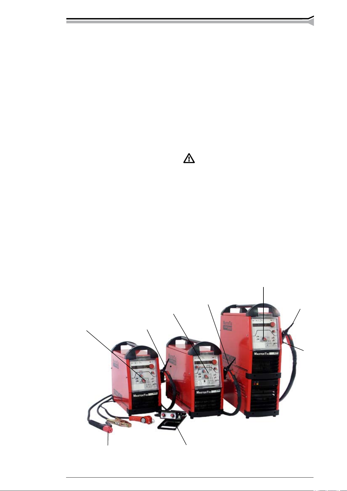
2. INSTALLATION
2.1. CABLING THE MACHINE
Shielding gas hose
Gas-cooled TIG
torch
Cable for MMA
welding
Return current
cable
Remote control unit
Mains cable
Shielding gas hose
Cable for MMA
welding
Remote control
unit
Gas-cooled TIG
torch
Return current
cable
Mains cable
Page 6
6 – Mastertig aC/DC 2000, 2500, 2500W, 3500W/0701 © keMppi oy
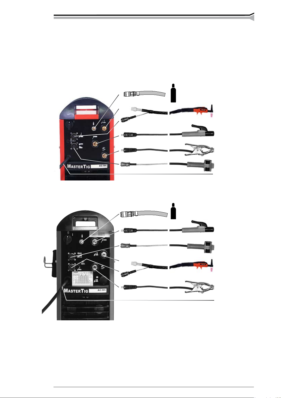
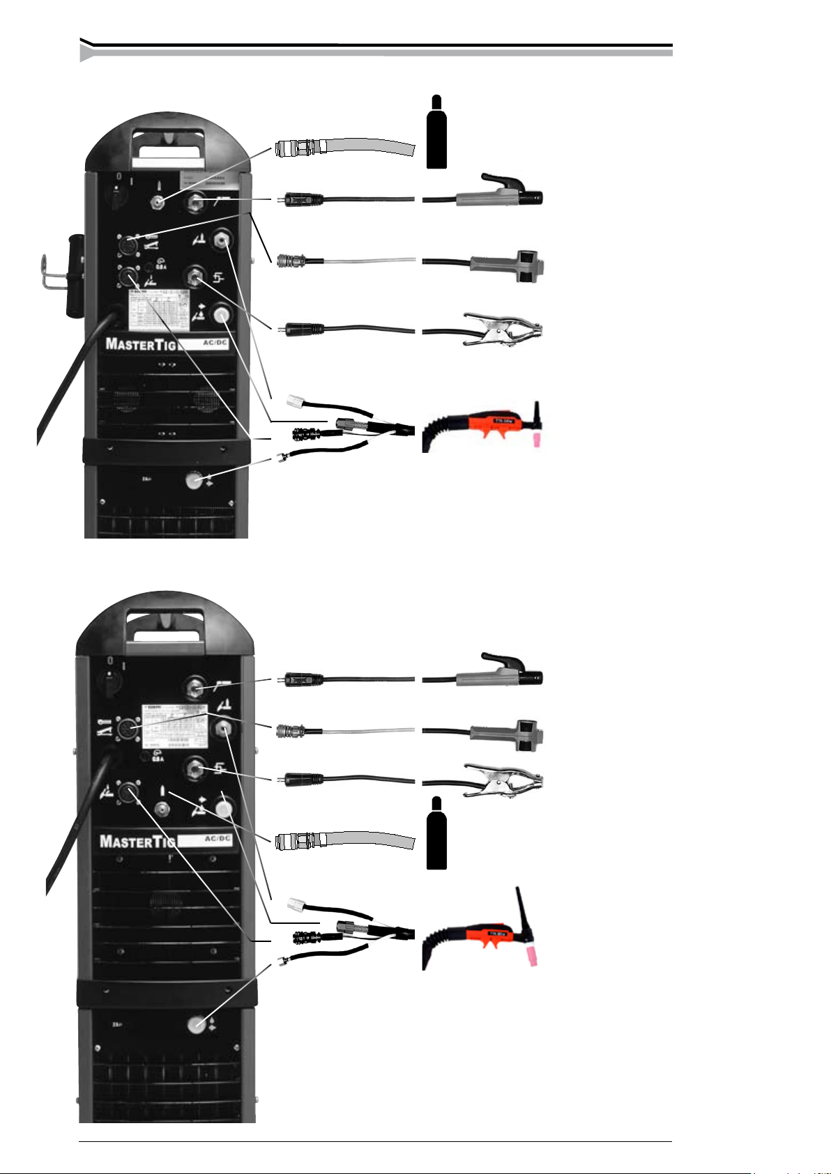
Mastertig AC/DC 2500W
Mastertig AC/DC 3500W
Shielding gas hose
Cable for MMA
welding
Remote control unit
Return current cable
Water-cooled TIG
torch
Cable for MMA
welding
Remote control unit
Return current
cable
Shielding gas hose
Water-cooled TIG
torch
Page 7
Mastertig aC/DC 2000, 2500, 2500W, 3500W/0701 – 7© keMppi oy
2.2. SITING THE MACHINE
When siting the machine, the following have to be considered:
Site the machine on a xed dry base, which does not cause dust etc. into the suction air of
cooling.
– Make sure that the machine is placed away from the line of particle spray from grinding
tools.
– Ensure free circulation of the cooling air. Make sure that there is at least a 20 cm free dis
-
tance both in front of and at the rear of the machine for the circulation of the cooling air.
– Protect the machine against heavy rain and in hot circumstances against direct sunshine.
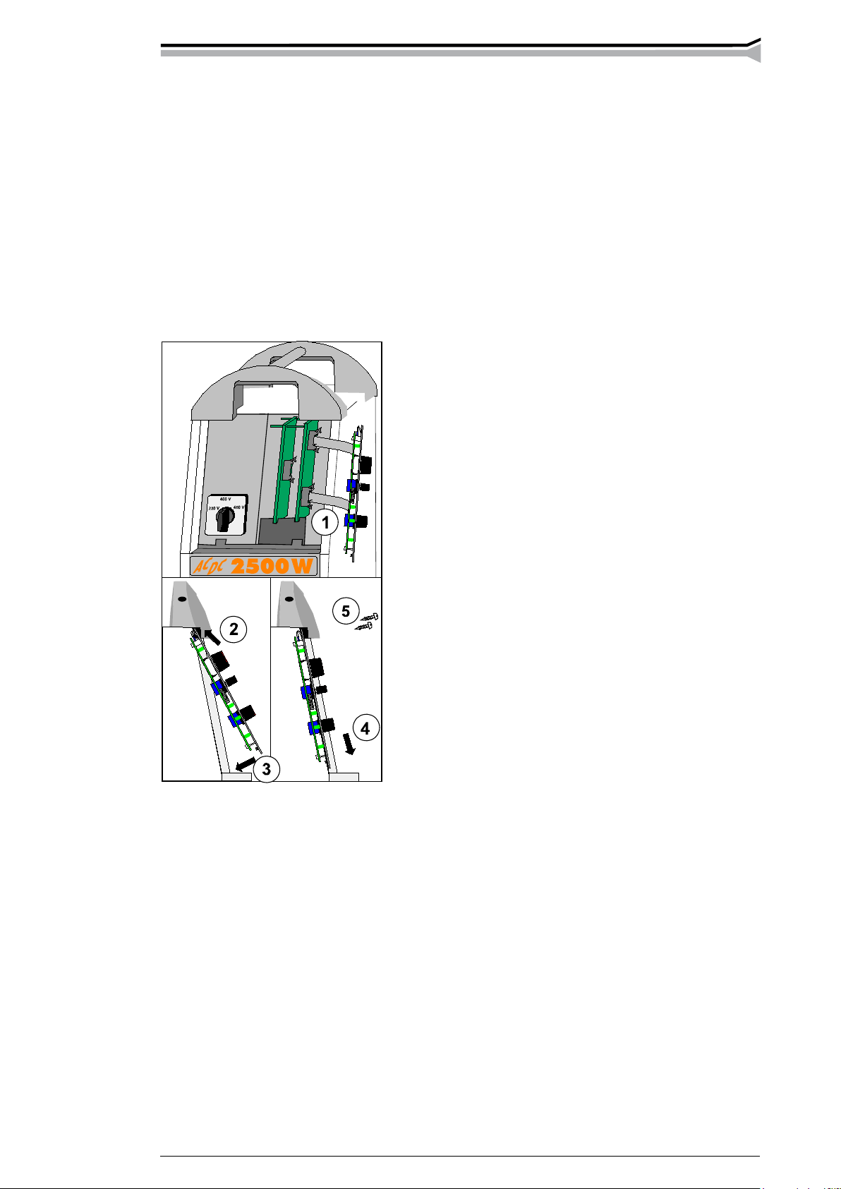
2.3. START OF INSTALLATION
Mastertig AC/DC 2500 and -2500W: Check rst that the
mains voltage change-over switch is in right position.
If it is necessary to change mains cable, do it before mounting to the wheel barrow T 120. Otherwise you possibly
have to dismount the machine.
Before connecting the machine to the mains supply, one
of the three panels, the ACDC panel, the ACDC minilog
or the ACDC pulse panel, has to be installed. Installation
instructions 4283280 are in the package of the panel.
Page 8
8 – Mastertig aC/DC 2000, 2500, 2500W, 3500W/0701 © keMppi oy
2500, 2500W, 3500W
2.4. CONNECTING THE MACHINE TO THE MAINS SUPPLY
The installation or replacement of the mains cable and the plug may be carried
out only by an authorized electric shop or electrician.
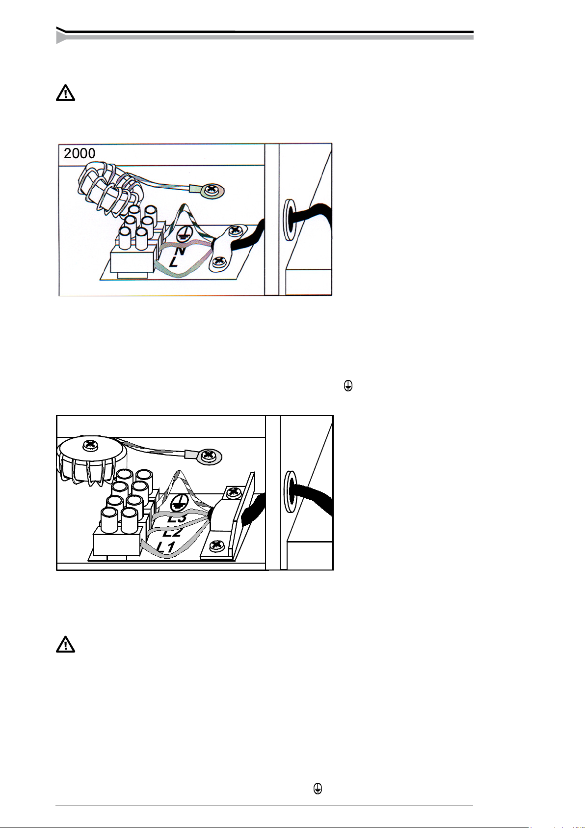
Mastertig AC/DC 2000
The machine is delivered with a mains cable with an earthed plug for connection to a mains
supply of 230 V.
To be noted when replacing the mains cable:
The lifting handles, cover and the right-hand-side plate have to be opened. The cable in brought
to the machine through the inlet ring on the rear panel and fastened with a cable clamp. The
phase lead of the cable are coupled to connector L, the blue to the connector of the N lead and
the yellow-green to the connector of the protective grounding lead .
Mastertig AC/DC 2500, -2500W and -3500W
The machine is delivered with a 5 m mains cable (4×2.5 mm2) without a plug. Mains cable is
suitable for all mains voltages with recommended fuse size (please look at Technical data table).
4×6 mm2 cable can be connected to the machine, if local regulations are requiring it.
If you use greater fuse size than recommended big short circuit current can
cause extra damage in case of failure.
Mastertig AC/DC 2500, -2500W
Before connecting the machine to the mains supply, make sure that the voltage change-over
switch of the machine is turned to the position corresponding to the mains supply voltage (230 /
400 / 460 V).
When replacing the mains cable, note the following:
The lifting handles, cover and right-hand-side plate of the machine have to be opened. The cable
is brought to the machine through the inlet right on the rear panel and fastened with a cable
clamp. The phase leads of the cable are coupled to connectors L1, L2 and L3; the yellow-green
is coupled to the connector of the protective grounding lead .
Page 9
Mastertig aC/DC 2000, 2500, 2500W, 3500W/0701 – 9© keMppi oy
Reference max electrode diameters and yield
electrode type yield 2000 2500, 2500W 3500W
Fe-rutile 95 % ø 4 ø 5 ø 6
Fe-base 100 % ø 4 ø 5 ø 6
Fe-high-yield 180 % ø 2,5 ø 4 ø 5
250-270 % - - - ø 4 ø 5
Ss-rutile - - - ø 4 ø 6 ø 6
Ss-base - - - ø 4 ø 6 ø 6
Ss-high-yield 150 % ø 3,25 ø 5 ø 6
Hard facing by welding 100 % ø 3,25 ø 5 ø 6
2.5. CABLE FOR MMA WELDING AND RETURN
CURRENT CABLE
The welding cables have to be at least 16 mm2 copper cables for Mastertig AC/DC 2000 and 25
mm2 copper cables for Mastertig AC/DC 2500, Mastertig AC/DC 2500W and 50 mm2 copper
cables for Mastertig AC/DC 3500W. Thinner cables will cause voltage losses and heating.
Connect the grounding clamp of the return cable carefully, preferably directly to the piece to be
welded. Use as short welding cables as possible. Unnecessarily long cables will lower the maximum output voltage of the machine. Coiling of the excess cable lowers the output voltage of the
machine especially in AC welding and decreases the ignition spark.
Clean the fastening surface of any paint and rust!
2.6. THE WELDING TORCH
In Mastertig AC/DC 2000 and Masterig AC/DC 2500, only an gas-cooled torch can be used.
In Mastertig AC/DC 2500 W and -3500W, you can use either an gas-cooled or a water-cooled
torch. Make sure that the torch you are using is designed for the maximum welding current that
you need.
Never use a damaged torch!
2.7. ELECTRODES TO BE WELDED
With the Mastertig AC/DC power sources you can use all electrodes designed for DC or AC
welding within the current limits of the machine in question.
Mastertig AC/DC 2500, -2500W and -3500W power sources are suitable for carbon arc gouging
and cutting according to their maximum power.
2.8. TIG DC WELDING
DC– current is used typically when welding different kind of steel. We rekommend for DC–
welding a WC20 (grey) elctrode.
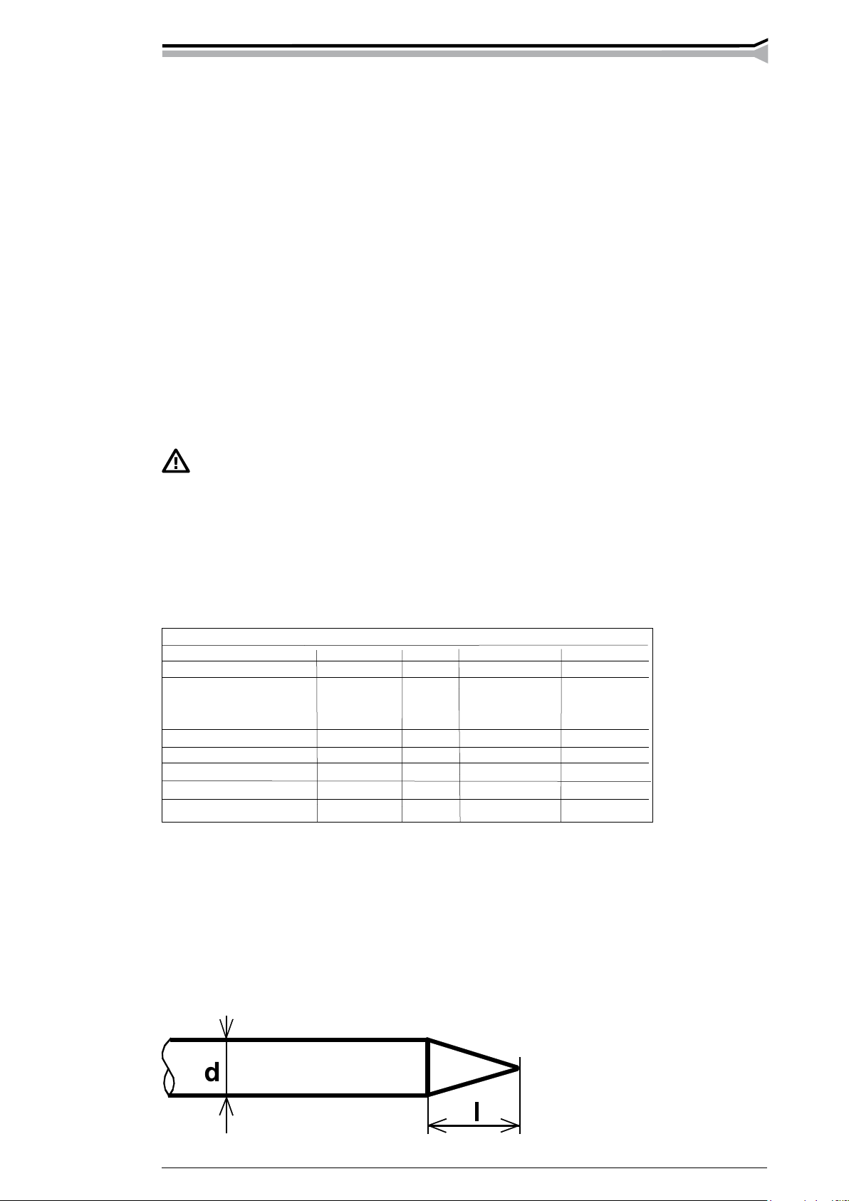
2.8.1. Sharpening of the electrode
The tip of the electrode is sharpened into a cone, so that the arc becomes steady and the thermal
energy is concentrated on the spot being welded. The length of the sharpening to the diameter
of the electrode:
with small current sharp l = 3 x d
with large current blunt l = 1 x d
Page 10
10 – Mastertig aC/DC 2000, 2500, 2500W, 3500W/0701 © keMppi oy
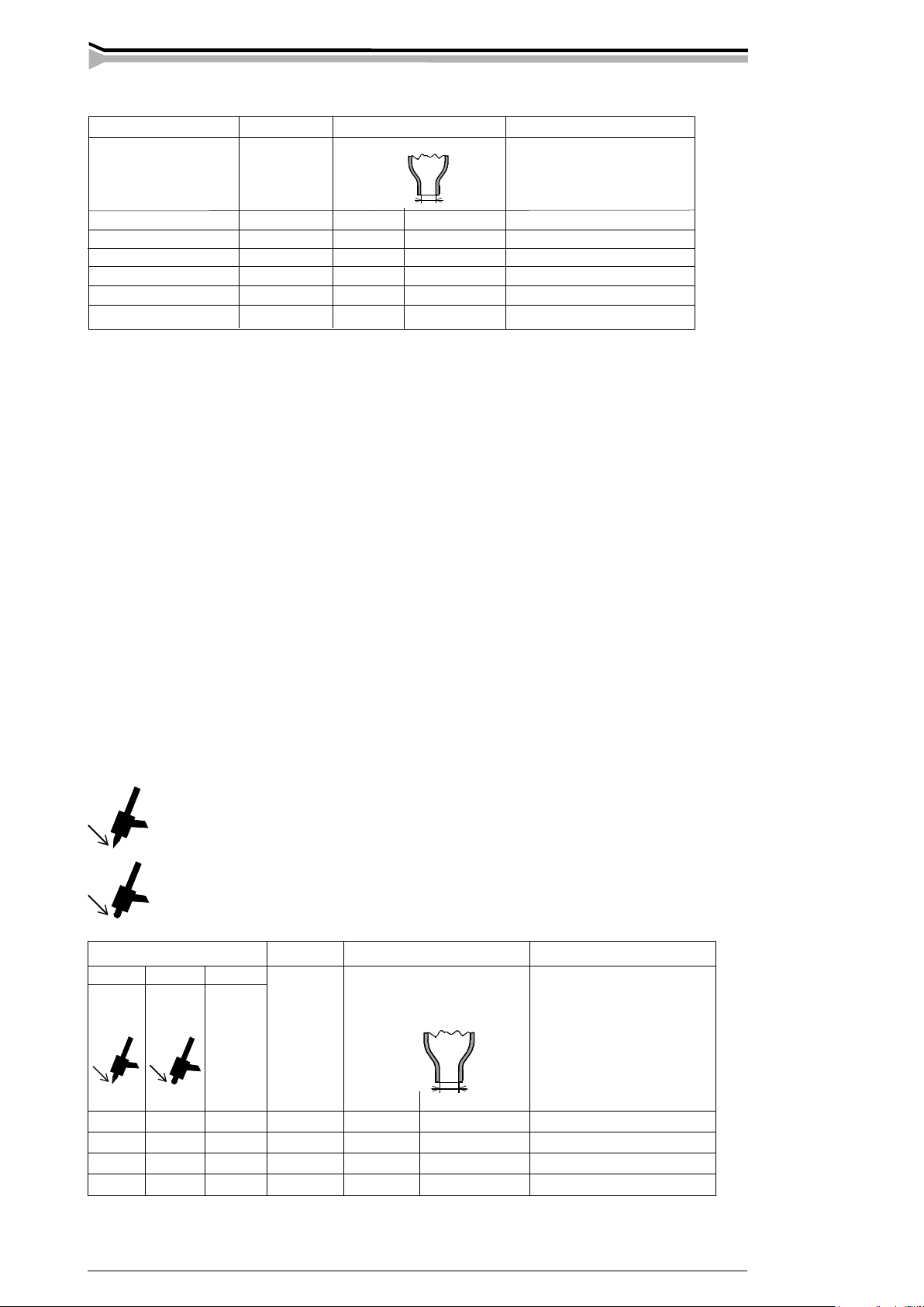
Choice of the electrode for DC welding. The table is only given as a guide.
2.9. TIG AC WELDING
AC-current is typically used when welding aluminium. We recommend for AC-welding a WC20
(grey) or a clean wolfram electrode (green).
2.9.1. Balance
In AC-welding the ratio between the positive and negative half-cycle is called balance. With the
balance you can control heat between the electrode and work piece. When balance is positive,
it means that the positive half-cycle is longer than the negative, more heat is coming to the
electrode than to the work piece. Correspondingly when balance is negative, negative half-cycles
are longer, the work piece is hotter and the electrode is colder. Mastertig AC/DC-machines have
build-in BALANCE-automatism, which chooses automatically right balance value. User adjusts
the BALANCE-knob according to the electrode, and the machine takes care of the balance
control in different currents.
BALANCE automatics offers two benets as compared to a constant balance:
– In AC welding, you can use both a sharpened and a rounded (cut) electrode. When welding
starts, the machine will round the cut tip so that its is suitable.
– The current-range of the electrode is extended: the current of the lower end is lowered and
the current of the maximum end is increased.
With BALANCE automatics, you can use the position for a sharpened electrode with
a narrower arc to obtain a narrower seam and to a deeper penetration than with a
rounded electrode. A narrow seam is useful especially in llet welding.
When using a rounded electrode, the arc is broad and the cleaning area of the arc is
also wider, so it can be used for end-to-end seams and outer corners.
The table is only given as a guide.
The table and the panel scale are based on the use of WC20 (grey). When using pure wolfram
electrode (green) the tip rounds off slightly.
Welding current range Electrode Gas nozzle Gas ow rate
DC- WC20 Argon
A ø mm number ø mm l / min
5...80 1,0 4/5 6,5/8,0 5...6
70...140 1,6 4/5/6 6,5/8,0/9,5 6...7
140...230 2,4 6/7 9,5/11,0 7...8
225...350 3,2 7/8 11,0/12,5 8...10
330...350 4 10 16 10...12
Welding current range
Electrode Gas nozzle Gas ow rate
min. min. max.
WC20 Argon
A A A ø mm number ø mm l / min
15 25 90 1,6 4/5/6 6,5/8,0/9,5 6...7
20 30 150 2,4 6/7 9,5/11,0 7...8
30 45 200 3,2 7/8/10 11,0/12,5/16 8...10
40 60 350 4,0 10/11 16/17,5 10...12
Page 11

Mastertig aC/DC 2000, 2500, 2500W, 3500W/0701 – 11© keMppi oy
E
B
D
C
A
G
2.10. SHIELD GAS
Handle gas bottle with care. There is a risk for injury if gas bottle or bottle valve
is damaged!
Argon, argon-helium or helium gases are normally used as shield gas. Check that the gas bottle
valve is suitable for the gas. The ow rate is set according to the welding power used in the job.
A suitable ow rate is normally 8 - 10 l/min. If the gas ow is not suitable, the welded joint will
be sporous. Contact your local Kemppi-dealer for choosing gas and equipment.
The following installing instructions are valid for most of the gas ow regulator types:
1. Step aside and open the bottle valve (A) for a while to blow out possible impurities from
the bottle valve.
2. Turn the press regulation screw (B) of the regulator until no spring pressure can be felt.
3. Close needle valve, if there is one in the regulator.
4. Install the regulator on bottle valve and tighten connecting nut (C) with a wrench.
5. Install hose spindle (D) and jacket nut (E) into gas hose and tighten with hose clamp.
6. Connect the hose with the regulator and the other end with the wire feed unit.
Tighten the jacket nut.
7. Open bottle valve slowly. Gas bottle pressure meter (F) shows the bottle pressure.
Note! Do not use the whole contents of the bottle. The bottle should be lled when the
bottle pressure is 2 bar.
8. Open needle valve if there is one in the regulator.
9. Turn regulation screw (B) until hose pressure meter (G) shows the required ow
(or pressure). When regulating ow amount, the power source should be in switched on and
the gun switch pressed simultaniously.
Close bottle valve after having nished welding. If the machine will be out of use for a long
time, unscrew the pressure regulation screw.
2.10.1. Installing gas bottle
Always fasten gas bottle properly in vertical position in a special holder on the
wall or on a carriage. Remember to close gas bottle valve after having nished
welding.
Parts of gas ow regulator
A Gas bottle valve
B Press regulation screw
C Connecting nut
D Hose spindle
E Jacket nut
F Gas bottle pressure meter
G Gas hose pressure meter
F
Page 12

12 – Mastertig aC/DC 2000, 2500, 2500W, 3500W/0701 © keMppi oy
12
13
14
6
5
4
3
1
22
21
19
11
12
13
14
6
5
4
3
2
1
22
21
20
19
3. OPERATING PANELS
BASIC
MINILOG
Page 13

Mastertig aC/DC 2000, 2500, 2500W, 3500W/0701 – 13© keMppi oy
10
11
12
13
14
15
6
5
4
3
1
22
21
9 8 7
16 17 18 19 20
2
PULSE
1. Selection switches for TIG welding: TIG HF = spark TIG and TIG CONTACT = contact TIG
2. Frequency of AC welding, FREQUENCY 50 ... 200 Hz
3. Adjustment of post-gas time 0 ... 100 s
4. Adjustment potentiometer of the down-slope time of the welding current 0 ... 15 s
5. Current adjustment knob I2, used also to adjust the values of the parameters with keys.
6. Selection of local / remote control REMOTE and at the same time the key for code locking
CODE LOCK/ENTER
7. Adjustment of the pulse current of Pulse TIG PULSE 3 ... 200A, 250A, 350A
and the adjustment of the pulse ratio RATIO 10 ... 75 %
8. Selection key of Pulse TIG
9. Adjustment of the background current of Pulse TIG BACK 20 ... 40 %
and adjustment of the frequency FREQUENCY 0.1 ... 300 Hz
10. Adjustment of the start current, starting with a current lower than the welding current SOFT START,
or with a current higher than the welding current HOT START -70 ... +50 %
11. Selection of Minilog operations and adjustment of the current level MINILOG -80 ... +20 %
12. Adjustment of the pre-gas time, and at the same time the key for code locking CODE LOCK.
13. Adjustment of the up-slope time of the welding current 0 ... 5 s
14. Selection of fusion spot welding and adjustment of time, SPOT WELD 0 ... 10 s
15. Selection of the operation mode of the torch switch 2T / 4T.
16. Calling the welding parameters from the memory or from the panel MEM. / PANEL.
17. Saving the welding values in the memory SAVE.
18. Selection key of the memory channel CHANNEL 1 ... 9
19. Selection key for broken-arc method BROKEN ARC.
20. Adjustment of the dynamics (arc force) of MMA welding DYNAMICS -9 ... 9
21. Selection key of MMA welding MMA
22. Adjustment potentiometer of the form of the AC TIG arc BALANCE -70 ... +70 %
Page 14

14 – Mastertig aC/DC 2000, 2500, 2500W, 3500W/0701 © keMppi oy
3.1. NUMERICAL DISPLAYS AND SIGNAL LIGHTS OF THE PANEL
Machine on Heat protection Wrong mains voltage, over or under-voltage
Display of
welding current
or set value
current
Display of
welding voltage
or parameters
Units of the display
The signal light of thermal protection is on when the machine has over-heated. Let the machine on so
that the fan will cool the machine. Wait until the light goes off, and you can continue welding.
The light for the wrong voltage turns on if the mains voltage is too high or too low. Check the voltage
setting of the machine and/or the mains voltage. The wrong voltage light will also turn on if there is a
momentaneous over-voltage in the mains supply.
The current is displayed with a tolerance of 3 % ± 2 A; the voltage with a tolerance of 3 % ± 0.2 V.
3.2 USE OF THE REMOTE CONTROL
The remote control is selected from the key REMOTE. With
the remote control you can adjust the welding current of MMA
and TIG welding. The values of the parameters (up-slope and
down-slope times, gas ow times etc.) are adjusted from the
current knob.
With remote control unit C 100AC you can also change the
welding method (MMA / TIG). The machine selects the polarity
(type of current) in accordance with an advance selection on
the panel.
3.3. MMA WELDING
3.3.1. Selection of type of current
Select MMA welding by pressing the selection key of MMA welding. The signal light of the
type of current indicates the current type selected: AC, DC-, DC+.
Change the current type by pressing the MMA selection key again and the current type will
change and the signal light will show the current type selected.
3.3.2. Broken arc method
Press the BROKEN ARC key and the signal light for broken arc method turns on.
A broken arc method has to be used if the seam to be welded cannot tolerate the heat of a
continuous arc. The heat of the welding is controlled by breaking the arc. Usually the reason is
thin material or various ttings. In the broken arc method position, the arc breaks faster and the
ignition pulse is smaller then in ordinary MMA welding.
Page 15

Mastertig aC/DC 2000, 2500, 2500W, 3500W/0701 – 15© keMppi oy
3.3.3. Control of MMA welding dynamics
(only with minilog and pulse panels)
Press the DYNAMICS key and you will see the numerical value corresponding to the dynamics
in the display. You can change the value by turning the current knob. Numerical value zero is the
normal setting for all MMA electrodes. When the value is adjusted negative (-1... 9), the arc is
softened. The amount of spatter decreases when welding at the upper end of the recommended
current range of the electrode. On the positive side (1...9) the arc is rough. It is suitable e.g. for
thin stainless steel rods when welding near the lower end of the
recommended current range.
3.4. TIG WELDING
3.4.1. Selection of TIG welding and type of current
Press the selection key next to the selected TIG method, spark
TIG (TIG HF) or contact TIG (TIG CONTACT), and the
signal light next to the key will show the method. You can
change the type of current by pressing the selection key again.
(If you want to select DC+ as the current type for TIG, press
both TIG keys at the same time.)
3.4.2. Spark ignition
Use contact ignition when you are welding in a environment where there are
sensitive electronic equipements. The ignition spark can cause interferences in
equipement near the welding machine.
The arc is ignited with a high-frequency, high-voltage spark without touching the work piece. If
the arc is not ignited in spite of the spark within one second, you will have to try the ignition
again by pressing the torch switch. In some cases the spark ignition works better if you touch the
work piece with the gas nozzle lightly before the ignition.
3.4.3. Contact ignition
Press the electrode lightly against the work piece (1). Press the switch and the shielding gas will
start to ow and a small current will pass through the electrode. Lift the electrode away from the
work piece by turning it so that gas nozzle rests against the work piece (2 ja 3), and the arc will
ignite and the current will rise to the welding level within the up-slope time (4).
Page 16

16 – Mastertig aC/DC 2000, 2500, 2500W, 3500W/0701 © keMppi oy
4T
2T
4T
2T
/
2
21
2
241
3
2
2
2
2 41 3
3.4.4. Use and selection of operation of the torch switch
The operation of the torch switch is selected by pressing the 2T/4T key.
2-function (2T) / spark ignition
1. Press the torch switch. The gas starts to ow and after the pre-
gas time selected, the arc is ignited and the current rises to the
welding level within the selected up-slope time.
2. Release the torch switch, and the welding current will drop in
accordance with the selected down-slope time. After the arc is
turned off, the gas will continue to ow for the post-gas time.
2-function (2T) / contact ignition
1. Press the tip of the torch lightly against the work piece.
2. Press down the torch switch.
3. Lift the electrode slowly away from the work piece. The arc
will ignite and the welding current will rise to the welding
level within the selected up-slope time.
4. Release the torch switch, and the welding current will drop in
accordance with the selected down-slope time. After the arc is
turned off, the shielding gas will continue to ow for the post-
gas time.
The down-slope time of the welding current can be interrupted by quickly
pressing the torch switch.
You can go back to the welding current from the down-slope current by
pressing the torch switch down. After that, the current will rise at a rate
corresponding to the down-slope time.
4-function (4T) / spark ignition
1. Press the torch switch down. The shielding gas starts to
ow.
2. Release the torch switch. The ignition spark ignites the
arc and the current will rise to the welding level within
the up-slope time.
3. Press the torch switch down. The welding continues.
4. Release the torch switch, and the current starts to drop
and after the selected down-slope time the arc is broken.
After this, the shielding gas will ow for the time
selected.
Page 17

Mastertig aC/DC 2000, 2500, 2500W, 3500W/0701 – 17© keMppi oy
2
2
15 s
CODE LOCK
2
251 3
4
4-function (4T) / contact ignition
1. Press the electrode lightly against the work piece.
2. Press the torch switch down for a moment.
3. Lift the electrode slowly away from the work piece. The
arc will ignite and the welding current will rise to the
welding level within the up-slope time.
4. Press the torch switch down. The welding continues.
5. Release the torch switch, and the welding current will
drop and stop after the selected down-slope time. After
the arc is turned off, the shielding gas will continue to
ow for the post-gas time.
By pressing the torch switch during the down-slope time of the current, the
current will remain at that level as long as the switch is pressed down. After
the release of the switch, the current will drop further.
By pressing the switch down for a moment, you can raise the welding
current back to the welding level.
3.4.5. Adjustment of the down-slope time of the welding current
The adjustment of the down-slope time is done from the potentiometer. The time can be adjusted between 0 - 15 s. When you
adjust the down-slope time, you can see the time in seconds in
the right-hand numerical display. After 5 seconds, the display
will return to the start status.
3.4.6. Adjustment of the up-slope time of the welding current
1. Press the key next to the up-slope of the current pattern.
The right-hand numerical display will show the up-slope
time in seconds.
2. Select the desired value by turning the current knob
(0 - 5 s). 5 seconds after the adjustment, the displays will
return to show the set value of the current.
3.4.7. Adjustment of the pre-gas and post-gas times
1. Press the switch in the panel next to the gas bottle of the current model of either the pre-gas
or the post-gas.
2. Turn the current knob until the value that you want is shown in the right-hand display. (Pregas 0 - 5 s, post-gas 3 - 100 s)
3.4.8. Adjustment of the form of the arc, BALANCE
The BALANCE function will adjust the balance so that it is suitable for the selected electrode
and current. At the same time, it adjusts the pre-heating of the tip of the electrode at the start
in accordance with the tip form selected.
Page 18

18 – Mastertig aC/DC 2000, 2500, 2500W, 3500W/0701 © keMppi oy
BALANCE
2.4
3.2
4.0
AC
AC
FREQUENCY
50 - 200 Hz
MINILOG
OFF
-80%
+20%
2
1a. When welding with a sharpened electrode, turn the control
knob to the left edge of the range of the electrode that you
have selected. (Narrow arc, deep penetration, range: small
seams)
1b. When welding with a rounded electrode, turn the control knob
to the right edge of the range of the electrode that you have
selected.
2. If you want more heat to the electrode, turn the knob to the
right, or if you want less heat, turn it to the left.
3.4.9. Frequency adjustment of TIG AC welding
(only with minilog and pulse panel)
The frequency of AC welding can be adjusted by means of the MINILOG and PULSE PANEL.
Raising the frequency will make the arc slightly more stable and narrow, but it will increase the
noise caused by arc.
1. Press the FREQUENCY key in the AC square.
2. Adjust the frequency with the current knob. The adjustment range of the
frequency is 50 ... 200 Hz. When leaving the factory, the frequency of the
machine is 60 Hz.
3.4.10. Minilog operation (only with minilog and pulse panel)
With the Minilog operation you can select two currency levels, the welding
current and the base current, and you can move from one to the other by quickly
pressing the torch. The Minilog operation can be used only with a 4-function torch
switch operation.
The selection and adjustment of the Minilog operation is done by means of the
potentiometer. When the potentiometer is in the OFF position, the operation is
not in use. The welding current is selected from the current knob like usually. The
Minilog knob is used to select a basic current, the minimum of which is 80 %
You can move from the welding current to the basic current by quickly pressing the torch.
By quickly pressing it again, you move back to the welding current. The signal lights on the
panel show you the current level you are on.
You can stop the welding by a longer pressing of the torch switch (> 0.7 s).
The Minilog operation can be used to adjust the heat, if the work piece is overheated or if you
need more heat for a moment.
With the Minilog operation you can go to a lower current level for example when you change
the position or the grip of the ller material wire without having to stop the welding to do that.
A lower current can also be used as the crater lling current if you do not want to use the down-
slope time for that.
below the welding current and the maximum is 20 % above the
current level. During the adjustment, you can see the set value of
current in amperes in the current display.
Page 19

Mastertig aC/DC 2000, 2500, 2500W, 3500W/0701 – 19© keMppi oy
PULSE
ON /
OFF
PULSE
RATIO
BACK.
FREQUENCY
OFF
HOT
START
SOFT
START
+50%
-70%
2
2
0 - 10 s
SPOT
WELD
3.4.11. Pulse welding (only with the pulse panel)
1. Switch the pulse welding on by means of the pulse-section key ON/OFF.
2. Adjust the average current that you want from the current adjustment knob.
The current display will show you the average current.
3. Press the key BACK. FREQUENCY once. The text bAc of the right-hand
display shows you that now you can adjust the background current from the
current knob. The background current is proportional to the average current,
but it is shown in the current display in amperes.
4. Press the key BACK. FREQUENCY again. The text FrE of the current display shows that
now you can adjust the pulse frequency. The pulse frequency is shown in Hz.
5. Press the key PULSE RATIO once. You will see the pulse current in the current display. The
right-hand display reads PUL. You can also adjust the pulse current, but please note that this
will change the average current.
6. When you press the key PULSE RATIO again, you can adjust the pulse ratio, rAt. The pulse
ratio is shown as a percentage of the total length of the cycle.
7. When you press either of the parameter keys a third time, the adjustment goes back to the
average current AvE.
3.4.12. Control of the start current (only with the pulse panel)
By means of the control potentiometer of the start current you can
select either a soft, normal or hot start. The start current is available
only with a 4-function torch switch operation.
By turning the potentiometer to OFF, you have a normal start (see
the use of the torch switch / 4-function)
By turning the potentiometer to the left, you get a soft start (SOFT START).
When you raise the torch switch, the current rises in accordance with the
up-slope of the start current to the start current, which is smaller than the
welding current.
From the start current, you can move to the welding current by pressing the
torch switch for a short moment.
The start current is proportional to the welding current. You can see the
value of the start current in the numerical display during the control.
When you turn the potentiometer to the right, the start current is higher than
the welding current (HOT START). Otherwise the start is made in the same
way as with a soft start.
3.4.13. Fusion spot welding (only with a pulse panel)
Select fusion spot welding by pressing the special operation key SPOT WELD.
To show that you have selected fusion spot welding, the signal light next to the
key goes on. You can select the spot time that you want with the current knob.
The time selected is shown in the numerical display during the adjustment. Five
seconds after the adjustment, the display returns to the set value of the current and
you can adjust the welding current.
The time shown in the display means the time you have the welding current. The
down-slope and the up-slope times are increasing the burning time of the arc.
Page 20

20 – Mastertig aC/DC 2000, 2500, 2500W, 3500W/0701 © keMppi oy
SAVINGMEM.
PANEL
SAVINGMEM.
PANEL
SAVINGMEM.
PANEL
SAVINGMEM.
PANEL
SAVINGMEM.
PANEL
3.5. MEMORY FUNCTIONS (ONLY WITH THE PULSE PANEL)
By means of the memory functions you can save 9 panel settings in the permanent memory. All
adjustable or chosen values are saved in the memory. When the memory function is not in use, the
numerical display of the memory section is black.
With the CHANNEL key you can select the channel to be read and used for the saving of a setting.
The MEM / PANEL key is used to select whether to use the values in the memory or values control-
led from the panel.
The function of the SAVE key is two-phased. When you press it once, you select the values to be
saved. In this case the light SAVING is blinking to show that you are performing a saving operation.
When the light is blinking, you can nd the channel into which you want to save the values. When
you press the key again, the information is saved in the memory.
of the current. You can see the other values of the welding parameters
by pressing the parameter key or by turning the potentiometer. All the
values are locked, which means that you cannot change them while the
MEM signal light is on.
2. If you want to change the values found, press the MEM / PANEL key
and the PANEL signal light comes on and you can change the values.
3.5.2. Saving a welding situation (parameters) in the memory
3.5.1. Calling the values from the memory
1. Press the CHANNEL key so many times that the numerical channel display shows the
number of the channel that you want. At the same time, the signal lights of the panel show
you the selections of the selected channel and the current display shows you the set value
1. Press the SAVE key once and the SAVING light starts to blink.
You have good welding values, which you want to save in the memory.
2. Press the CHANNEL key so many times that the number of the channel
in which you want to save the values is shown in the numerical display.
3. Now press the SAVE key again and the values are saved in the memory.
Note! When you are saving (= the SAVING light is blinking) and you have rolled the number of
the channel that you want by using the CHANNEL key, you can see the previous values of that
channel by pressing the MEM / PANEL key to bring the panel to the MEM status, so that you
can check the present values of that channel. In this case the values to be saved will not change.
After the check, press the MEM / PANEL key again and you can again see the values to be
saved and you can save them by pressing SAVE.
3.6. CODE LOCKING
The welding machine has a theft protection. You can install a three-digit machine-specic code
into the machine, which the user must know in order to turn the machine on. The code is saved
in the panel. If you change the panel the code follows the panel.
When the machine leaves the factory, the code locking operation is not on.
Page 21

Mastertig aC/DC 2000, 2500, 2500W, 3500W/0701 – 21© keMppi oy
3.6.1. Installing the code locking
1. Press the pre-gas key (CODE LOCK) and the key of the remote control (REMOTE / CODE
LOCK/ENTER) at the same time.
2. Select the rst digit from the current adjustment knob (e.g. 4).
3. Press the accept key (REMOTE / CODE LOCK/ENTER).
4. Select the second digit from the knob (e.g. 3) and again accept it by pressing the key
(REMOTE / CODE LOCK/ENTER).
5. Select the third digit in the same way (e.g. 2).
Now the code locking is on with the number that you have chosen (e.g. 432).
3.6.2. Turning the machine on when the code locking is on
When you turn on a machine in which the code locking is on, you must always feed in the
opening code that you have installed in order to be able to use the machine.
1. Feed in the rst digit from the current adjustment knob.
2. Accept the digit by pressing (REMOTE / CODE LOCK/ENTER).
3. Feed in the second and third digits in the same way.
The machine is ready for use.
If you enter wrong code, you can try again by turning the machine off and on.
If you can not open the machine, you do not remember the right code, contact
an authorized service agent.
3.6.3. Removal of code locking
1. Press the key for pre-gas (CODE LOCK) and the key for remote control (REMOTE / CODE
LOCK/ENTER) at the same time.
2. Feed in the digits of the code in the same way as when opening the machine. The code
locking will be removed after you have fed in the last digit.
3. Turn the machine off. The machine is now ready for use.
3.6.4. Changing the code
1. Remove the code locking in accordance with the above instruction.
2. Install the code locking again.
Page 22

22 – Mastertig aC/DC 2000, 2500, 2500W, 3500W/0701 © keMppi oy
P
e
4. COOLING UNIT
(only Mastertig AC/DC 2500W, -3500W)
no pressure
overheated liquid
gas- / water-cooled torch GAS / WATER
test run of the circulation of the liquid TEST
Filling in the liquid and checking the liquid level is done by pulling open the hatch in the lower
part of the machine so that you can see the lling hole for the liquid. The cooling units tank
is lled with 20 – 40 % glycol / water mixture according to antifreeze requirements. Instead of
glycol / water mixture you can also use another liquid according to your experience.
The circulation of the liquid is operation-controlled, which means that the liquid is circulating
only during welding and for a while after the welding.
5. INTERNAL PROTECTIONS OF THE MACHINE
5.1. OVERHEATING PROTECTION
The yellow signal light of the overheating protection comes on and the machine stops
when the machine has overheated. The machine may overheat if the machine is loaded
for a long time with a current higher than 100 % of the duty cycle or when the
circulation of the cooling air is prevented.
5.2. OVER-VOLTAGE PROTECTION OF THE MAINS SUPPLY VOLTAGE
If the over-voltages in the mains supply are so high that they can endanger the
machine, the supply of the machine is immediately turned off. If the over-voltages
are short in duration, this may be seen as short breaks in the current. The signal
light of the panel showing an over / under-voltage comes on during a long period
of over-voltage.
5.3. THE WRONG VOLTAGE SELECTION
Mastertig ACDC 2500, Mastertig ACDC 2500W
If a multi-voltage machine is connected to the wrong voltage, the machine will not
start and the signal light in the front panel comes on to indicate this. The machine will
not be damaged if it is connected to the wrong voltage for a short time. Unplug the
machine from the mains supply and select the correct voltage from the switch under
the front panel.
5.4. PROTECTION OF A WATER-COOLED TORCH
Mastertig ACDC 2500W and -3500W
If the switch of the cooling unit is in the position for an gas-cooled torch and you start welding
with a water-cooled torch and a current is over 60 A, the welding is broken.
Page 23

Mastertig aC/DC 2000, 2500, 2500W, 3500W/0701 – 23© keMppi oy
C 100C
C 100D
C 100AC
6. ACCESSORIES
6.1. REMOTE CONTROL UNITS
C 100C Control of MMA / TIG welding current, memory scale 1 - 10.
C 100D Control and ne-tuning of MMA / TIG welding current, memory scale 1 - 10.
C 100AC Control of MMA / TIG welding current, memory scale 1 - 10 and MMA /
TIG selection.
C 100F Foot pedal control unit for TIG welding
– start function
– adjustment of the welding current with pedal movements
– limitation of the welding-current range with min and max potentiometers
6.1.1. Connecting the foot pedal unit:
The foot pedal unit has two connections, which are connected
to the remote control and start connections in the rear of the
power source. When using the foot pedal unit, the
maximum current output of the machine is ca. 30 %
below its maximum output unless the machine is calibrated for
the foot pedal unit.
6.1.2. Calibration of the machine for the foot pedal unit:
1. Turn the machine off.
2. Press the REMOTE key and at the same time turn the machine on; the display will show
the text rEn 01.
3. Turn the current adjustment knob so that the display will show rEn 02. (01=C 100C, 02=C 100F)
4. Press the REMOTE key so that the setting is saved in the memory.
6.2. WHEEL BARROWS AND TRANSPORT CHASSISES
T 120 (transport unit)
Mastertig AC/DC 2000, 2500, 2500W, 3500W
lifting ear
Do not lift the welding machine and
the transport unit with a gas bottle.
T 22 (transport unit)
Mastertig AC/DC
2500, 2500W, 3500W
lifting ears
on both sides
(total 4 pcs)
Page 24

24 – Mastertig aC/DC 2000, 2500, 2500W, 3500W/0701 © keMppi oy
7. EXTRA FUNCTIONS
There are extra functions and selections in the machine, which are not seen in the panel. The welder
needs these functions not in normal welding, but they may be a solution in some special cases.
These function are called jumper functions, because they are behind jumper numbers. Function can
be On/Off -type or adjustable parameter.
Jumper functions
1. Turn off the machine.
2. Press the [POST GAS] button and at the same time turn the machine on.
You can see text (J01 OFF) or (J01 ON) on the panel.
3. Choose jumper number you need by pressing the [REMOTE] button.
4. Change jumper setting with the pulse potentiometer.
5. When you have done the changes needed press the [POST GAS] button. All jumper settings are
then saved in the memory.
Factory settings are underlined.
J01: [On] = slope of up slope is constant, time depends on set value of current.
[
Off] = up slope time is independent of set value of current.
J02: [On] = slope of down slope is constant, time depends on set value of current.
[
Off] = down slope time is independent of set value of current.
J03: [
On] = TIG antifreeze is on.
[Off] = TIG antifreeze is not in use.
J04: [On] = manual AC balance control.
[
Off] = balance function in use.
J05: [On] = tag welding automatics is not in use.
[
Off] = tag welding automatics on.
J06: [On] = down slope of TIG is minimum end level current.
[
Off] = end level current is 20 % of the welding current
J07: [Off] = open-circuit voltage is 70 V
[On] = open-circuit voltage is 12 V without VRD card, 22 V with VRD card
J08: [On] = when stopping welding with 4T function the down slope starts by pressing torch
connector. Slope continues as long as you press the connector. Current stays at
end level in case you press longer than down slope´s normal time (look J06).
[
Off] = normal 4T function.
J09: [Off] = primary frequency is 18 kHz / 36 kHz (depending on the set value)
[On
] = primary frequency is 18 kHz in the whole current range.
J10: [
Off] = hot/soft - start function is not in use on 2T function.
[On] = hot/soft - start function is in use on 2T function.
J11: hot/soft - start time adjustment on 2T function (0.0 … 9.9 s). J10 has to be in position [On]
J12: [
Off] = on 2T function the down slope is cut off by a short press of the switch
[On] = on 2T function the down slope does not cut off by a short press of the switch
J13: [
Off] = on TIG AC the level of positive half-cycle changes when the balance and set value
change (both with auto and manual balance)
[On] = on TIG AC the level of positive half-cycle is always the same as the level of the
negative half-cycle
Page 25

Mastertig aC/DC 2000, 2500, 2500W, 3500W/0701 – 25© keMppi oy
8. MAINTENANCE
The amount of use and an unusual working environment have a special effect on the need for
maintenance. Proper use and preventive maintenance will help to ensure trouble-free operation
of the machine without unexpected interruptions.
8.1. THE WELDING TORCH
Due to high temperatures and wear, the welding end of the TIG torch requires maintenance
most, but also the condition of the other parts should be checked regularly.
8.1.1. The welding end
Check that...
– all insulations of the welding end are undamaged and in place.
– the gas nozzle is undamaged and suitable for the work.
– the ow of the shielding gas is free and even.
– the electrode is undamaged. Use an electrode size and tip sharpening which are suitable for
the welding job. Sharpen the electrode lengthwise.
– the fastening parts of the electrode are undamaged and that the electrode is tightly fastened
in its place.
8.1.2. The torch cable
Check that...
– the insulation of the handle and the torch cable are undamaged.
– the torch cable has no sharp bends.
Always replace any damaged parts immediately!
Follow the instructions of the torch manufacturer in all maintenance and repair measures.
8.2. CABLES
Check the condition of the welding and connection cables daily.
J14: [Off] = limit of short press of the TIG switch is 0.7 s
[On] = limit of short press of the TIG switch is 0.3 s
J15: [
Off] = AC TIG welding is started in the positive half-cycle
[On] = AC TIG welding is started in the negative half-cycle
J16: 0 -> 2.0 = ratio for the start length of DC in AC TIG
factory setting is 1.0
J17: 0 -> 2.0 = ratio for MMA ignition pulse
factory setting is 1.0
J18: ---------- vacant
J19: ---------- vacant
Do not use damaged cables!
Check also that the mains connection cables that you use are in good condition
and that they comply with all the regulations!
Mains connection cables may be repaired and installed only by an authorized electric shop or
electrician.
Page 26

26 – Mastertig aC/DC 2000, 2500, 2500W, 3500W/0701 © keMppi oy
8.3. THE POWER SOURCE
NOTE! Disconnect the plug of the machine from the mains socket and wait for ca. 2 minutes
(capacitor charge) before removing the casing plate.
Check at least very six months:
– The electric connections of the machine– clean any oxidized parts and tighten any loose
ones.
NOTE! You must know the correct tension torques before you start to repair the connections.
– Clean the inner parts of the machine from dust and dirt e.g. with a soft brush and a
vacuum-cleaner.
Do not use pressurized air, because there is the danger that the dirt is packed even more
tightly in the gaps of the cooling proles. Do not use a pressure washing device.
Only an authorized electric shop or electrician may repair the machine.
8.4. REGULAR MAINTENANCE
KEMPPI Service Repair Shops handle regular maintenance by agreement.
Regular maintenance includes e.g. the following:
– Cleaning of the machine.
– Checking and maintenance of the welding tools.
– Checking the clamps, switches and potentiometers.
– Checking the electric connections.
– Checking the mains cable and plug.
– Replacement of any parts that are damaged or in poor condition.
– Maintenance testing. The operation and performance values of the machine are checked and,
where necessary, adjusted by means of test equipment.
9. OPERATION DISTURBANCES
In the case of operation disturbances, contact an authorized KEMPPI Service Repair Shop.
Check the maintenance parts before sending the machine to the service shop.
10. DISPOSAL OF THE MACHINE
Do not dispose of electrical equipment together with normal waste!
In observance of European Directive 2002/96/EC on Waste Electrical and Electronic
Equipment and its implementation in accordance with national law, electrical equipment
that has reached the end of its life must be collected separately and returned to an
environmentally compatible recycling facility. As the owner of the equipment, you should
get information on approved collection systems from our local representative.
By applying this European Directive you will improve the environment and human
health!
Page 27

Mastertig aC/DC 2000, 2500, 2500W, 3500W/0701 – 27© keMppi oy
11. ORDERING NUMBERS
Mastertig AC/DC 2000 6162000
Mastertig AC/DC 2500 6162500
Mastertig AC/DC 2500W 6162505
Mastertig AC/DC 3500W 6163505
ACDC panel 6162801
ACDC minilog 6162802
ACDC pulse 6162803
Accessories
T 120 transport unit 6185252
T 22 transport unit 6185256
GH 20 (gun holder) 6256020
Remote control units
C 100C 6185410
C 100D 6185413
C 100AC 6185417
C 100F 6185405
Cables
Extension cable for remote control 10 m 6185456
Start extension cable C 100F 10 m 6185310
Welding cables
Cable for MMA welding 25 mm2 5 m 6184201
25 mm
2
10 m 6184202
Cable for MMA welding 50 mm
2
5 m 6184501
50 mm
2
10 m 6184502
Return current cable 25 mm
2
5 m 6184211
25 mm
2
10 m 6184212
Return current cable 50 mm
2
5 m 6184511
50 mm
2
10 m 6184512
TIG torches, gas-cooled
TTK 130 4 m 627063004
TTK 130 8 m 627063008
TTK 130 16 m 627063016
TTK 130F 4 m 627063104
TTK 130F 8 m 627063108
TTK 130F 16 m 627063116
TTK 160 4 m 627066004
TTK 160 8 m 627066008
TTK 160 16 m 627066016
TTK 160S 4 m 627066204
TTK 160S 8 m 627066208
TTK 160S 16 m 627066216
TTK 220 4 m 627072004
TTK 220 8 m 627072008
TTK 220 16 m 627072016
TTK 220S 4 m 627072304
Page 28

28 – Mastertig aC/DC 2000, 2500, 2500W, 3500W/0701 © keMppi oy
TTK 220S 8 m 627072308
TTK 220S 16 m 627072316
TIG torches, water-cooled
TTK 250WS 4 m 627075704
TTK 250WS 8 m 627075708
TTK 250WS 16 m 627075716
TTK 300W 4 m 627080504
TTK 300W 8 m 627080508
TTK 300W 16 m 627080516
TTK 350W 4 m 627085504
TTK 350W 8 m 627085508
TTK 350W 16 m 627085516
Page 29

Mastertig aC/DC 2000, 2500, 2500W, 3500W/0701 – 29© keMppi oy
Mains voltage
Rated power
Welding current range
Connection cable
Fuse
Maximum load**)
Fuse
Maximum load***)
Open circuit voltage
Frequency of AC*)
Efciency
Power factor
Cos i
Open circuit power
Storage temperature range
Operating temperature range
Temperature class / Degree of protection
External dimensions
Weight
1~ 50 / 60 Hz
TIG max.
TIG 100 %
MMA max.
MMA 100 %
TIG DC
AC
MMA DC
AC
TIG AC 30 % ED (T = 40 °C)
TIG AC 100 % ED (T = 40 °C)
MMA 20 % ED (T = 40 °C)
MMA 100 % ED (T = 40 °C)
TIG AC 50 % ED (T = 40 °C)
TIG AC 100 % ED (T = 40 °C)
MMA 60 % ED (T = 40 °C)
MMA 100 % ED (T = 40 °C)
(AC and DC)
xed / adjustable
length
width
height
230 V ± 10 %
200 A / 6,8 kVA
150 A / 4,5 kVA
160 A / 7,3 kVA
100 A / 4,2 kVA
3 A / 10 V ... 200 A / 18 V
10 A / 10 V ... 200 A / 18 V
10 A / 10 V ... 160 A / 26,4 V
11 A / 10 V ... 160 A / 26,4 V
3 x 2,5 mm
2
S- 3
16 A delayed
200 A / 18 V
150 A / 16 V
160 A / 26,4 V
100 A / 23,6 V
20 A delayed
200 A / 18 V
150 A / 16 V
160 A / 26,4 V
140 A / 23,6 V
70 V DC
60 Hz / 50 ... 200 Hz
75 % (160 A / 26,4 V)
0,8 (160 A / 26,4 V)
0,96 (160 A / 26,4 V)
18 W
-40 ... +60 °C
-20 ... +40 °C
B (130 °C), H (180 °C) / IP 23C
540 mm
260 mm
510 mm
30 kg
12. TECHNICAL DATA
*) Adjustable with MINILOG- and PULSE panels.
**) Fuse reduces maximum load.
***) Use of 20 A fuse requires changing of connection cable.
The products meet conformity requirements for CE marking.
Mastertig AC/DC 2000
Page 30

30 – Mastertig aC/DC 2000, 2500, 2500W, 3500W/0701 © keMppi oy
Mastertig AC/DC 2500 2500W
Mains voltage
Rated power (U1=400V)
Connection cable
Fuse
Welding current range
Maximum load (T=40 °C)
Maximum load (T=20 °C)
Open circuit voltage
Frequency of AC
Efciency
Power factor
Open circuit power
Storage temperature range
Operating temperature range
Temperature class / Degree of protection
External dimensions
Weight
Max liquid pressure of cooling unit
Rated power of cooling unit
3~ 50 / 60 Hz
TIG 70 % ED
TIG 100 % ED
MMA 40 % ED
MMA 100 % ED
230 V
400 V
460 V
TIG DC
AC
MMA
TIG AC 60 % ED
70 % ED
100 % ED
MMA DC 40 % ED
100 % ED
TIG AC 100 % ED
MMA DC 80 % ED
100 % ED
(AC and DC)
xed / adjustable*)
length
width
height
230 V ± 10 %
400 V ± 10 %
460 V ± 10 %
250 A / 7,5 kVA
200 A / 6,7 kVA
250 A / 10,3 kVA
200 A / 7,9 kVA
4 x 2,5 mm2 S - 5 m
20 A delayed
16 A delayed
16 A delayed
3 A / 10 V ... 250 A / 20 V
10 A / 10 V ... 250 A / 20 V
10 A / 20 V ... 250 A / 30 V
– –
250 A / 20 V
220 A / 18,8 V
250 A / 30 V
200 A / 28 V
250 A / 20 V
250 A / 30 V
240 A / 29,6 V
70 V DC
60 Hz / 50 ... 200 Hz
80 % (250 A / 30 V)
0,9 (250 A / 30 V)
18 W
-40 ... +60 °C
-20 ... +40 °C
B (130 °C), H (180 °C) / IP 23C
690 mm 690 mm
260 mm 260 mm
550 mm 830 mm
39 kg 65 kg
– – – – 350 kPa
– – – – 1300 W
*) Adjustable with MINILOG- and PULSE panels.
**) Fuse can reduce maximum load.
The products meet conformity requirements for CE marking.
Page 31

Mastertig aC/DC 2000, 2500, 2500W, 3500W/0701 – 31© keMppi oy
Mastertig AC/DC 3500W
Mains voltage
Rated power (U1=400V)
Connection cable
Fuse
Welding current range
Maximum load (T=40 °C)
Maximum load (T=20 °C)
Open circuit voltage
Frequency of AC
Efciency
Power factor
Open circuit power
Storage temperature range
Operating temperature range
Temperature class / Degree of protection
External dimensions
Weight
Max liquid pressure of cooling unit
Rated power of cooling unit
– – – –
400 V ± 10 %
– – – –
350 A / 11,7 kVA
280 A / 8,2 kVA
350 A / 15,7 kVA
280 A / 11,2 kVA
4 x 2,5 mm
2
S - 5 m
20 A delayed
3 A / 10 V...350 A / 24 V
10 A / 10 V...350 A / 24 V
10 A / 20 V...350 A / 34 V
350 A / 24 V
280 A / 21,2 V
350 A / 34 V
280 A / 31,2 V
310 A / 22,4 V
350 A / 34 V
300 A / 32 V
70 V DC
60 Hz / 50 ... 200 Hz
80 % (350 A / 34 V)
0,9 (350 A / 34 V)
18 W
-40 ... +60 °C
-20 ... +40 °C
B (130 °C), H (180 °C) / IP 23C
690 mm
260 mm
870 mm
74 kg
350 kPa
1300 W
3~ 50 / 60 Hz
TIG 60 % ED
TIG 100 % ED
MMA 60 % ED
MMA 100 % ED
400 V
TIG DC
AC
MMA
TIG AC 60 % ED
100 % ED
MMA DC 60 % ED
100 % ED
TIG AC 100 % ED
MMA DC 80 % ED
100 % ED
(AC ja DC)
xed / adjustable*)
length
width
heigh
*) Adjustable with MINILOG- and PULSE panels.
**) Fuse can reduce maximum load.
The products meet conformity requirements for CE marking.
Page 32

32 – Mastertig aC/DC 2000, 2500, 2500W, 3500W/0701 © keMppi oy
13. TERMS OF GUARANTEE
Kemppi Oy provides a guarantee for products manufactured and sold by them if defects in
manufacture and materials occur. Guarantee repairs must be carried out only by an Authorised
Kemppi Service Agent. Packing, freight and insurance costs to be paid by orderer. The guarantee is
effected on the date of purchase. Verbal promises which do not comply with the terms of guarantee
are not binding on guarantor.
Limitations on guarantee
The following conditions are not covered under the terms of guarantee: defects due to natural wear
and tear, non-compliance with operating and maintenance instructions, connection to incorrect or
faulty supply voltage (including voltage surges outside equipment spec.), incorrect gas pressure,
overloading, transport or storage damage, re of damage due to natural causes i.e. lightning or
ooding.
This guarantee does not cover direct or indirect travelling costs, daily allowances or accommodation.
Note: Under the terms of guarantee, welding torches and their consumables, feeder drive rolls and
feeder guide tubes are not covered. Direct or indirect damage due to a defective product is not
covered under the guarantee. The guarantee is void if changes are made to the product without
approval of the manufacturer, or if repairs are carried out using non-approved spare parts.
The guarantee is also void if repairs are carried out by non-authorised agents.
Undertaking guarantee repairs
Guarantee defects must be informed to Kemppi or authorised Kemppi Service Agents within the
guarantee period. Before any guarantee work is undertaken, the customer must provide proof of
guarantee or proof of purchase, and serial number of the equipment in order to validate the guarantee.
The parts replaced under the terns of guarantee remain the property of Kemppi.
Following the guarantee repair, the guarantee of the machine or equipment, repaired or replaced,
will be continued to the end of the original guarantee period.
Page 33

KEMPPI OY
PL 13
FIN – 15801 LAHTI
FINLAND
Tel (03) 899 11
Telefax (03) 899 428
www.kemppi.com
KEMPPIKONEET OY
PL 13
FIN – 15801 LAHTI
FINLAND
Tel (03) 899 11
Telefax (03) 7348 398
e-mail: myynti.fi @kemppi.com
KEMPPI SVERIGE AB
Box 717
S – 194 27 UPPLANDS VÄSBY
SVERIGE
Tel (08) 590 783 00
Telefax (08) 590 823 94
e-mail: sales.se@kemppi.com
KEMPPI NORGE A/S
Postboks 2151, Postterminalen
N – 3103 TØNSBERG
NORGE
Tel 33 34 60 00
Telefax 33 34 60 10
e-mail: sales.no@kemppi.com
KEMPPI DANMARK A/S
Literbuen 11
DK – 2740 SKOVLUNDE
DANMARK
Tel 44 941 677
Telefax 44 941 536
e-mail:sales.dk@kemppi.com
KEMPPI BENELUX B.V.
Postbus 5603
NL – 4801 EA BREDA
NEDERLAND
Tel +31 (0)76-5717750
Telefax +31 (0)76-5716345
e-mail: sales.nl@kemppi.com
KEMPPI (UK) Ltd
Martti Kemppi Building
Fraser Road
Priory Business Park
BEDFORD, MK443WH
ENGLAND
Tel 0845 6444201
Fax 0845 6444202
e-mail: sales.uk@kemppi.com
KEMPPI FRANCE S.A.
65 Avenue de la Couronne des Prés
78681 EPONE CEDEX
FRANCE
Tel (01) 30 90 04 40
Telefax (01) 30 90 04 45
e-mail: sales.fr@kemppi.com
KEMPPI GmbH
Otto – Hahn – Straße 14
D – 35510 BUTZBACH
DEUTSCHLAND
Tel (06033) 88 020
Telefax (06033) 72 528
e-mail:sales.de@kemppi.com
KEMPPI SP. z o.o.
Ul. Piłsudskiego 2
05-091 ZA¸BKI
Poland
Tel +48 22 781 6162
Telefax +48 22 781 6505
e-mail: info.pl@kemppi.com
KEMPPI WELDING
MACHINES AUSTRALIA PTY LTD
P.O. Box 404 (2/58 Lancaster Street)
Ingleburn NSW 2565, Australia
Tel. +61-2-9605 9500
Telefax +61-2-9605 5999
e-mail: info.au@kemppi.com
OOO KEMPPI
127018 Moscow, Polkovaya str. 1,
Building 6
e-mail: info.ru@kemppi.com
ООО КЕМППИ
127018 Москва, ул. Полковая 1,
строение 6
Ver. 1 0
www.kemppi.com
 Loading...