

Page 1
ArcFeed
200, 300, 300P, 300RC
Operating manual • English
Käyttöohje • Suomi
Bruksanvisning • Svenska
Bruksanvisning • Norsk
Brugsanvisning • Dansk
Gebrauchsanweisung • Deutsch
Gebruiksaanwijzing • Nederlands
Manuel d’utilisation • Français
Manual de instrucciones • Español
Instrukcja obsługi • Polski
Инструкции по эксплуатации • По-русски
EN
FI
SV
NO
DA
DE
NL
FR
ES
PL
RU
操作手册 • 中文
ZH
Page 2

Page 3

OPERATING MANUAL
English
ArcFeed 200, 300, 300P, 300RC / © Kemppi Oy / 1117
Page 4

CONTENTS
EN
ArcFeed 200, 300, 300P, 300RC / © Kemppi Oy / 1117
1. PREFACE
1.1 General
1.2 About voltage-sensing technology
1.3 Introduction
........................................................................................................................................................ 3
................................................................................................................................................................. 3
................................................................................................ 3
..................................................................................................................................................... 4
2. BEFORE USE..............................................................................................................................................5
2.1 Connecting the cables ..............................................................................................................................5
2.2 Selecting the welding wire ...................................................................................................................5
2.3 Mounting the wire spool ........................................................................................................................ 5
2.4 Installing the MIG/MAG welding gun ............................................................................................6
3. MACHINE SETTINGS ......................................................................................................................6
3.1 Setting the maximum wire feed speed
3.2 Adjusting the pressure of the feed rolls .......................................................................................7
3.3 Adjusting the spool brake
3.4 Reversing polarity
........................................................................................................................................ 8
3.5 Changing the feed rolls
......................................................................................................................7
............................................................................................................................8
........................................................................................ 6
4. USING THE MACHINE ................................................................................................................ 10
4.1 Using the control panel functions ................................................................................................10
4.1.1 Switching the machine on and o .............................................................................................. 10
4.1.2 Selecting the CC or CV mode ........................................................................................................ 10
4.1.3 Selecting the welding gun operating mode ........................................................................... 11
4.1.4 Changing the wire feed speed adjustment scale ..................................................................12
4.1.5 Using the power source remote control (only 300 RC)........................................................ 12
4.2 Using the inside controls .....................................................................................................................13
4.2.1 Burn back time ................................................................................................................................... 13
4.2.2 Gas test ..................................................................................................................................................13
4.2.3 Wire inch ............................................................................................................................................... 13
4.2.4 Post gas time ....................................................................................................................................... 13
4.3 Hanging the device..................................................................................................................................13
5. MAINTENANCE .................................................................................................................................. 14
5.1 Daily maintenance
5.2 Regular maintenance ............................................................................................................................. 14
5.3 Disposal of the machine
..................................................................................................................................14
.......................................................................................................................14
6. ORDERING NUMBERS ...............................................................................................................15
7. TECHNICAL SPECIFICATIONS ........................................................................................ 16
2
Page 5

1. PREFACE
1.1 GENERAL
Congratulations on your choice of the Kemppi ArcFeed wire feeder. Used correctly, Kemppi
products can signicantly increase the productivity of your welding, and provide years of
economical service.
This operating manual contains important information on the use, maintenance and safety of
your Kemppi product. The technical specications of the equipment can be found at the end
of the manual.
Please read the manual carefully before using the equipment for the rst time. For your
own safety and that of your working environment, pay particular attention to the safety
instructions in the manual.
For more information on Kemppi products, contact Kemppi Oy, consult an authorised Kemppi
dealer, or visit the Kemppi web site at www.kemppi.com.
The specications presented in this manual are subject to change without prior notice.
Important notes
Items in the manual that require particular attention in order to minimise damage and
personal harm are indicated with the ’NOTE!’ notation. Read these sections carefully and follow
their instructions.
Disclaimer
While every eort has been made to ensure that the information contained in this guide
is accurate and complete, no liability can be accepted for any errors or omissions. Kemppi
reserves the right to change the specication of the product described at any time without
prior notice. Do not copy, record, reproduce or transmit the contents of this guide without
prior permission from Kemppi.
ArcFeed 200, 300, 300P, 300RC / © Kemppi Oy / 1117
EN
1.2 ABOUT VOLTAGESENSING TECHNOLOGY
The voltage-sensing wire feeder uses the welding voltage to generate the energy required for
controlling the wire feeder’s operations. Before starting to weld, you just select the desired
settings for the feeder and the power source according to the welding requirements, the base
and ller material, and the shielding gas to be used.
When you start welding in CC mode, the feeder controls the parameters so that the quality of
the welds always remains high.
In normal MIG/MAG welding, the parameters’ values are controlled by the power source via
the control cable, but voltage-sensing technology makes such a control cable between the
power source and the feeder unnecessary.
Constant Current (CC) power sources
The CC type of welding machine changes the wire feed speed according to the arc voltage.
The voltage will change with dierent arc lengths while only slightly varying the amperage.
Constant Voltage (CV) power sources
The CV type of welding machine maintains a relatively stable, consistent voltage regardless of
the amperage. It results in a relatively at volt-amp curve. The MIG/MAG welding machines are
typically CV type machines.
3
Page 6
1.3 INTRODUCTION
The Kemppi ArcFeed is a voltage sensing wire feeder for MIG/MAG welding. It can be
combined with a variety of power sources of various brands, also with the ones designed for
MMA welding. The recommended power sources to be used with Kemppi ArcFeed are Kemppi
Master 5001 and Kemppi Master MLS 3500.
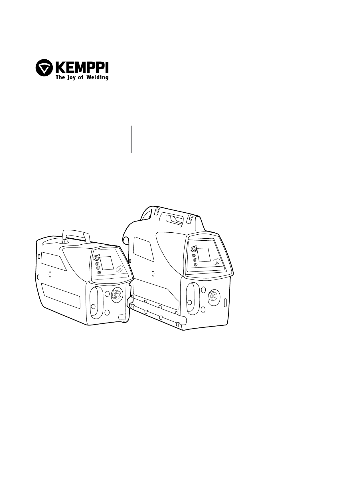
Front view
ArcFeed 200, 300, 300P, 300RC / © Kemppi Oy / 1117
1.
2.
3.
4.
EN
1. Main switch
2. Control panel
3. Welding cable connection
4. Locking latch
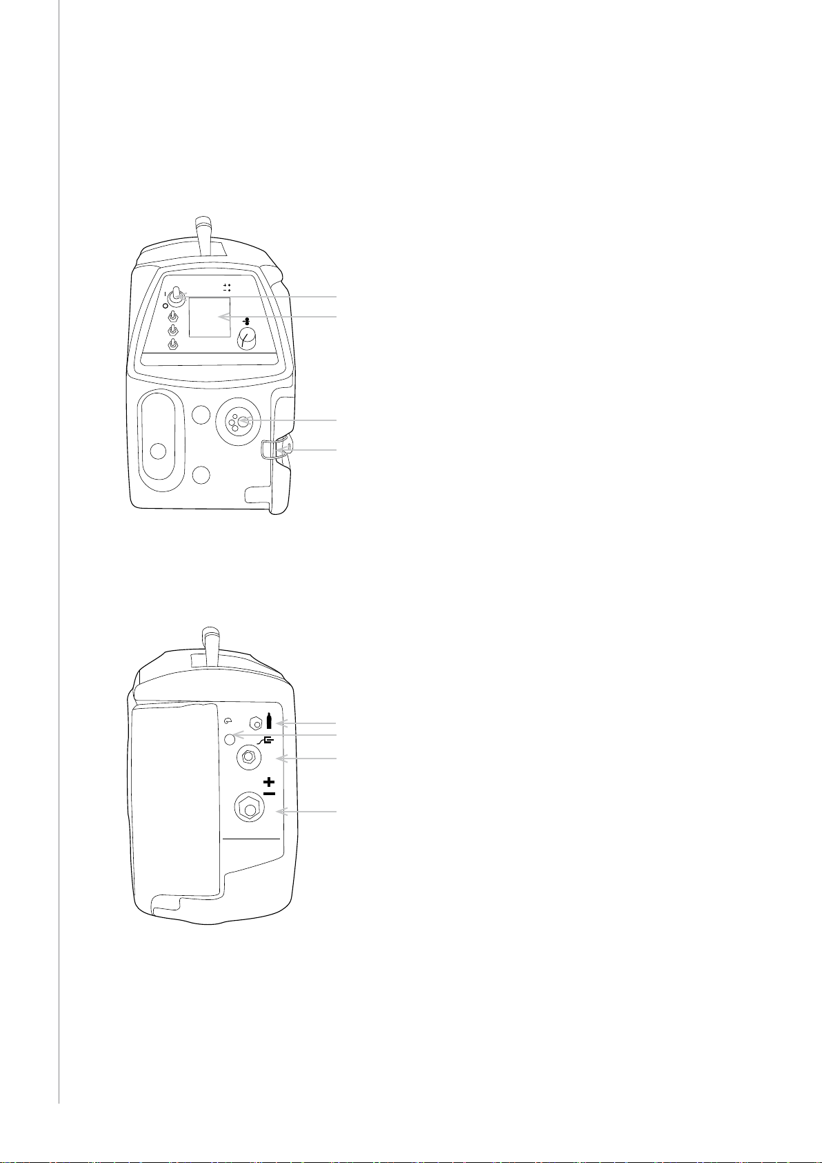
Back view
8 A
1.
2.
3.
4.
1. Shielding gas connection
2. Fuse
3. Earthing cable connection
4. Power source connection
4
Page 7

2. BEFORE USE
2.1 CONNECTING THE CABLES
Before starting to use the Kemppi ArcFeed, the necessary cable connections must be done in
the power source and the wire feeder.
To connect the cables, do the following:
1. Switch o the power source and connect its earthing clamp to the workpiece.
2. Switch o the Kemppi ArcFeed and connect the feeder earthing cable to the male DIX
connector (negative pole) in the back of the feeder. Then connect the feeder earthing
clamp to the workpiece.
3. Connect the welding cable from the power source to the female DIX connector (positive
pole) in the back of the feeder.
4. Connect the shielding gas hose to the connector (1) in the back of the feeder.
The Kemppi ArcFeed is now connected to the power source.
2.2 SELECTING THE WELDING WIRE
Select the suitable welding wire according to the base material, ller material and shielding
gas. The Kemppi ArcFeed is optimized for use with 1.2mm rutile ux-cored or solid wire, but
the following wires can be used:
• Flux-cored wires 1.2–2.0 mm
or up to 2.4 mm with the 300P model
• Innershield wires 1.6–2.0 mm
or up to 2.4 mm with the 300P model
• Solid wires 1.0–1.6 mm
In Kemppi ArcFeed 200 you can use 200mm wire spools. In models 300, 300P and 300RC, you
can use 300 mm wire spools.
ArcFeed 200, 300, 300P, 300RC / © Kemppi Oy / 1117
EN
2.3 MOUNTING THE WIRE SPOOL
Model 200:
A
1. Open the locking nut (A) of the spool holder.
2. Check the rotating direction of the wire spool and push the spool into its place so that it
rotates in the right direction.
3. Close the locking nut (A).
Models 300, 300P and 300RC:
1 2
1. Turn the locking knob (1) of the spool holder so that the locking clips are opened.
2. Check the rotating direction of the wire spool and push the spool into its place so that it
rotates in the right direction.
3. Turn the locking knob (2) of the spool holder to close the locking clips.
5
Page 8

2.4 INSTALLING THE MIG/MAG WELDING GUN
After mounting the wire spool, connect the welding gun cable to the connector (3) in the
front of the feeder.
Remember that you need to use suitable wire liner and feed rolls for the welding wire you are
using. Check also, that the correct groove is used in the feed rolls. If you need to change the
feed rolls or select dierent groove, look the instructions in chapter 3.5.
Before feeding the wire into the gun, release the wire from spool and cut o the bent length.
Be careful not to let the wire unwind from the spool. Check that the end of the wire has no
sharp edges, which may damage the wire guide tube and the contact tip of the welding gun.
NOTE! When feeding the welding wire into the gun, be sure that you are not pointing the gun at
anyone and that there isn’t anything in front of the gun. The cut wire can be very sharp.
To feed the wire from the spool to the welding gun, do the following:
1. Draw some loose wire from the wire spool and feed it through the back guide to the feed
rolls. Do not release pressure of feed rolls!
2. Locate the Wire inch button inside the feeder and push the button down to start the
wire inching. Let the wire go through the feed rolls and enter the wire liner.
3. Keep the wire inch button pressed, until the wire comes through the contact tip.
Check once again that the wire is still properly in the grooves of both feed roll pairs. Now the
ArcFeed 200, 300, 300P, 300RC / © Kemppi Oy / 1117
Kemppi ArcFeed is ready to weld.
NOTE! When welding gun trigger is pressed, the welding current is connected to the wire. To avoid
accidents and electric shock, it is not recommended to use gun trigger for wire inching.
EN
3. MACHINE SETTINGS
3.1 SETTING THE MAXIMUM WIRE FEED SPEED
The maximum wire feed speed of Kemppi ArcFeed is by default 18 m/min. This is enough
for most welding work. However, if you need higher speed, you can raise it to 25 m/min by
replacing the gear wheel D28 with a larger one, model D40.
NOTE! After changing the gear wheel, you must also set the right jumper setting on the control card
of the feeder.
To change the gear wheel, do the following:
1
6
2 4 5 2 3 6 3
6
Page 9

1. Open the locking lever (1) and remove the lower feed rolls (2). Open the screw (4) and
remove its washer. Then remove the gear wheel (5) from motor shaft.
2. Loosen the screws (6) by one turn and replace the gear wheel with the larger one.
Tighten the screw (4).
3. Put the lower feed rolls (2) back to their place, but don't tighten the screws.
4. Lift the motor so that there is a clearance of about 0.2 mm between the gear wheel and
the lower feed rolls.
5. Tighten screws (6). Check the gear clearance and adjust the motor position if necessary.
Tighten the feed roll srews (3).
To set the jumper setting, do the following:
1. Turn the feeder o.
2. Remove the plastic cover of the feeder by unscrewing the xing bolts.
3. Locate the control card inside the feeder and change the position of the jumper X6 so
that it connects the two pins.
4. Replace the cover of the feeder and tighten the xing screws.
3.2 ADJUSTING THE PRESSURE OF THE FEED ROLLS
1
ArcFeed 200, 300, 300P, 300RC / © Kemppi Oy / 1117
The pressure adjustment knob is located at the end of the locking lever (1). With the
adjustment knob you can adjust the pressure of the feed rolls, so that the wire runs smoothly
into the wire liner and brakes a little when coming out of the contact tip.
Make sure that the pressure is hard enough to avoid wire from slipping in the feed rolls, but
not too hard, because then it might atten the welding wire or damage its coating. Too hard
pressure may also cause friction and excessive wearing of the feed rolls.
3.3 ADJUSTING THE SPOOL BRAKE
The Kemppi ArcFeed is equipped with a spool brake to prevent the wire from unwinding and
tangling when the spool stops rotating at the end of the weld. The need for spool brake force
is increased with the increase of the wire feed speed.
The spool brake causes extra load to the wire feed motor, so do not apply too high brake force.
To adjust the spool brake in model 200, do the following:
A
B
EN
Increase the spool brake force by turning the brake adjusting knob (B) clockwise. To decrease
the brake force, turn the knob anticlockwise.
7
Page 10

To adjust the spool brake in models 300, 300P and 300RC, do the following:
Adjust the spool brake force through the hole in the spool locking mechanism with a screw
driver. Increase by turning the screw clockwise and decrease by turning it anticlockwise.
3.4 REVERSING POLARITY
Polarity of the welding machine refers to the pole in which the welding cable is connected.
In MIG/MAG welding the gun is usually connected to the plus pole, i.e. you are using positive
polarity. However, some ller wires are recommended to be welded with the gun in negative
ArcFeed 200, 300, 300P, 300RC / © Kemppi Oy / 1117
pole.
The Kemppi ArcFeed recognizes automatically the polarity you are using. This means that
it knows in which pole the welding cable is connected at the power source. The led on the
control panel indicates, whether you are using positive or negative polarity.
A
EN
To reverse the polarity, do the following:
Switch the welding cable and earthing cable from one pole to the other at the power source.
After that, the wire feeder recognizes the new polarity, and indicates it with the control panel
led.
3.5 CHANGING THE FEED ROLLS
There are dierent feed rolls for dierent welding wires. Also, each feed roll has two grooves
for dierent wire sizes.
The Kemppi ArcFeed is equipped with standard feed rolls, which are equipped with plain
grooves. These feed rolls can be used in welding with all kinds of wires. There are, however,
following feed roll groove shapes available for special purposes:
• Knurled groove is designed for cored wires and steel wires.
• U groove is designed for aluminium wires.
• Trapezoidal groove is designed for heavy welding applications.
The feed rolls and the wire liners have following colour codes in order to make identication
easier.
Feed rolls
colour of filler wire ø mm
white 0.6 and 0.8
red 0.9, 1.0, 1.2
yellow 1.4, 1.6, 2.0
black 2.4
Wire guide tubes
colour of filler wire ø mm
orange 0.6-1.6
blue over 1.6
8
Page 11

To change feed rolls, do the following:
1. Remove the feed rolls by unscrewing their xing screws.
2. Insert the new feed rolls into their place.
3. Select the right groove according to the wire you are using. See the instructions below.
4. Fasten the feed rolls with their xing screws and drive the wire into the welding gun as
instructed in chapter 2.4 'Installing the welding gun'.
To change the feed roll groove, do the following:
Each feed roll has two grooves for dierent ller wire diameters. When changing the feed rolls
select the groove according to the wire you are using.
1 1
Move the feed roll selector plates from one side to another.
Choose the correct groove by moving the groove selector plate (1) from one side to another in
feed roll as shown in the left-hand picture above.
ArcFeed 200, 300, 300P, 300RC / © Kemppi Oy / 1117
Move also the gear wheel selector plate.
When changing the feed roll groove you must also set the gear wheel to new position. This is
done by changing the gear wheel selector plate to the other side of the wheel.
EN
9
Page 12

4. USING THE MACHINE
Before starting to use the Kemppi ArcFeed wire feeder, you must be aware of the power
source type you are using ( either CC, constant current, or CV, constant voltage). The suitable
welding wire for the welding application must also be loaded in the feeder. For more
information, see Chapter 3.
4.1 USING THE CONTROL PANEL FUNCTIONS
6
7
1
EN
ArcFeed 200, 300, 300P, 300RC / © Kemppi Oy / 1117
4
1. ON/OFF switch
2. Gun operating mode selector (2T/4T)
3. CC/CV mode selector
4. Selector of the wire feed speed scale
5. Control knob.
6. Polarity indicator light
7. LCD display
4.1.1 Switching the machine on and o
To turn on the machine, set the main switch (1) to position ON. The LCD display of the control
panel lights up, and the machine is ready for use.
4.1.2 Selecting the CC or CV mode
With the CC/CV switch you can choose between constant current (CC) and constant voltage
(CV) type of power source. Set this switch according to the power source you are using. See
the documentation of the power source to nd its type.
2
3
5
10
Page 13

Adjusting the welding values in CC mode:
In CC mode, the display shows the open-circuit voltage and a reference value for welding
current. The reference value is a pre-dened value that has been determined using 1.2 mm
ux-cored wire.
Before starting to weld, use the control knob (5) to set the welding current to match the
welding current of the power source.
NOTE! When welding in CC mode, the dynamics setting at the power source must be set to its
maximum value. For instructions on how to do it, see the documentation of the power source.
ArcFeed 200, 300, 300P, 300RC / © Kemppi Oy / 1117
Adjusting the welding values in CV mode:
In CV mode the display shows the welding voltage and wire feed speed (WFS). The adjustment
range of the wire feed speed depends on the size of the wire drive roll. With the small drive roll
the WFS can be 0–18 m/min, and with the large drive roll it can be 0–25 m/min.
To adjust the welding values in CV mode, do the following:
1. Estimate the welding values to be used in the welding task.
2. At the power source, select the correct values for welding voltage and current, if
available.
3. Use the control knob of the Kemppi ArcFeed to enter the necessary WFS setting at the
feeder. The value is shown on the display.
EN
4.1.3 Selecting the welding gun operating mode
With the switch (2) you can set the MIG welding gun to either two-sequence (2T) or foursequence (4T) mode.
11
Page 14

EN
How to use the welding gun in 2T operating mode:
1. Press the gun trigger down to start welding.
2. Release the gun trigger to stop welding.
How to use the welding gun in 4T operating mode:
1. Press the gun trigger down to start the ow of the shielding gas.
2. Release the trigger to start welding.
3. Press the trigger down again to stop welding.
4. Release the switch again to stop the ow of the shielding gas.
4.1.4 Changing the wire feed speed adjustment scale
With the wire feed speed scale selector (4) you can aect the sensitivity of the control knob
when changing the wire feed speed.
• If you want to use exact wire feed speed adjustment, select the adjustment scale 0…9
(max 9 m/minute).
• If you want to use rough adjustment, select the adjustment scale 0…18
(max 18 m/minute).
4.1.5 Using the power source remote control (only 300 RC)
ArcFeed 300RC model is equipped with a power source remote control function. It allows
you to adjust the power source current level straight from the work site. Remote control can
ArcFeed 200, 300, 300P, 300RC / © Kemppi Oy / 1117
be used in constant current (CC) mode only. For more information on CC mode, see 4.1.2
“Selecting the CC or CV mode”.
To use the remote control
1. Turn the selector switch (2) to up position (REMOTE) and keep it there.
2. Select the desired welding current with the adjustment knob (1). The scale is suggestive
for Master 5001 power source.
3. Release the selector switch.
ARCFEED
300RC
100
50
25
10
REMOTE
150
200
300
400
A
1 adjusting knob
selector switch
2
12
Page 15

4.2 USING THE INSIDE CONTROLS
WIRE INCH
GAS TEST
POST GAS
1 2 3 4
ArcFeed 200 ArcFeed 300, 300P and 300RC
4.2.1 Burn back time
Burn back time control knob (1) lets you adjust the length of the post-welding current. Using
Burn back feature makes it easy to stop welding without wire sticking or burning back to the
contact tip.
4.2.2 Gas test
Gas test button (2) lets you test the shielding gas and measure the gas ow.
4.2.3 Wire inch
Wire inch button (3) lets you drive the welding wire without turning on the welding current.
This feature can be used for example when feeding in the new wire.
BURNBACK
WIRE INCH
GAS TEST
POST GAS
BURN
1
BACK
POST
WIRE
GAS
GAS
INCH
TEST
2
3
4
ArcFeed 200, 300, 300P, 300RC / © Kemppi Oy / 1117
EN
4.2.4 Post gas time
Post gas time (4) control knob lets you adjust the length of the post-welding gas ow. This
feature, combined with the burn back time, provides a smooth nish of the weld.
4.3 HANGING THE DEVICE
The Kemppi ArcFeed 200 wire feeder should never be hanged by its handle. Use a special
hanging frame for hanging it to a welding beam or other. See 'Accessories' in Chapter
'Ordering numbers' at the end of this manual.
The Kemppi ArcFeed 300, 300P and 300RC models can be hanged by their handle by using a
special hanging device, KFH 1000. See 'Accessories' in Chapter 'Ordering numbers' at the end
of this manual.
13
Page 16

5. MAINTENANCE
5.1 DAILY MAINTENANCE
Do the following always before starting to use the machine:
• Check the tightness of the earthing cable connections.
• Check the condition of mains and welding cables and replace damaged cables.
• Make sure that all extension cables used in the mains connection are in proper condition
and compliant with regulations.
NOTE! The mains cables may be repaired and installed only by electrical contractors and installers
authorised to perform such operations.
5.2 REGULAR MAINTENANCE
All electromechanical devices require routine service maintenance depending on usage. This
type of routine maintenance will prevent hazards and malfunctions.
We recommend that you schedule a service inspection of your welding machine every six
months. An authorised Kemppi service agent will inspect and clean your machine, ensuring
that all power connections are tight and secure. Power connections can become loose and
oxidised with frequent and high changes in temperature.
ArcFeed 200, 300, 300P, 300RC / © Kemppi Oy / 1117
5.3 DISPOSAL OF THE MACHINE
NOTE! Disconnect the machine from the mains power supply before handling electric cables.
EN
Do not dispose of electrical equipment with normal waste!
In observance of European Directive 2002/96/EC on waste electrical and electronic
equipment, and its implementation in accordance with national law, electrical equipment
that has reached the end of its life must be collected separately and taken to an appropriate
environmentally responsible recycling facility.
The owner of the equipment is obliged to deliver a decommissioned unit to a regional
collection centre, per the instructions of local authorities or a Kemppi representative. By
applying this European Directive you will improve the environment and human health.
14
Page 17

6. ORDERING NUMBERS
Wire feeders
Kemppi ArcFeed 200
Kemppi ArcFeed 300
Kemppi ArcFeed 300P
Kemppi ArcFeed 300RC
Accessories
Gas flow regulator
Hanging frame for ArcFeed 200
KFH 1000 hanger ArcFeed 300 and 300P
Protection slides for ArcFeed 200
Protection slides for ArcFeed 300 and 300P
Ordering number
6120200
6120300
6120310
6120301
W000364
6185285
6185100
6185286
6185287
Cables
Extension cable
Extension cable
Earthing cable
MIG guns
MMT 32
MMT 32
MMT 35
MMT 35
MMT 42
MMT 42
ArcFeed 200, 300, 300P, 300RC / © Kemppi Oy / 1117
70 mm², 25 m 6183725
70 mm², 10 m 6183710
16 mm², 5m SKM25 6184015
EN
3 m 6253213MMT
4,5 m 6253214MMT
3 m 6253513MMT
4,5 m 6253514MMT
3 m 6254213MMT
4,5 m 6254214MMT
15
Page 18

EN
7. TECHNICAL SPECIFICATIONS
Kemppi ArcFeed 200 300/300RC 300P
Rated power (W)
Welding wire types
Flux-cored wires, ø (mm)
Innershield wires, ø (mm)
Solid wires, ø (mm)
Loadability (A)
Wire feed speed with small drive roll (m/min)
Wire feed speed with large drive roll (m/min)
Storage temperature range
Operating temperature range
ArcFeed 200, 300, 300P, 300RC / © Kemppi Oy / 1117
Degree of protection
EMC class
Dimensions
Length (mm)
Height (mm)
Weight (kg)
Spool size (mm)
Gun connector type
60 % ED
80 % ED
100% ED
Width (mm)
150 150 150
1.2…2.0 1.2…2.0 1.2…2.4
1.6…2.0 1.6…2.0 1.6…2.4
1.0…1.6 1.0…1.6 1.0…1.6
300 300 300
0…18 0…18 0…9
0…25 0…25 0…12.5
-40 °C… +60 °C -40 °C… +60 °C -40 °C… +60 °C
-20 °C… +40 °C -20 °C… +40 °C -20 °C… +40 °C
IP23S IP23S IP23S
A A A
510 590 590
200 240 240
310 445 445
11 15 15
200 300 300
EURO EURO EURO
16
Page 19

ArcFeed 200, 300, 300P, 300RC / © Kemppi Oy / 1117
EN
17
Page 20

KEMPPI OY
Hennalankatu 39
PL 13
FIN-15801 LAHTI
FINLAND
Tel +358 3 899 11
Telefax +358 3 899 428
export@kemppi.com
www.kemppi.com
Kotimaan myynti:
Tel +358 3 899 11
Telefax +358 3 734 8398
myynti.@kemppi.com
KEMPPI SVERIGE AB
Box 717
S-194 27 UPPLANDS VÄSBY
SVERIGE
Tel +46 8 590 783 00
Telefax +46 8 590 823 94
sales.se@kemppi.com
KEMPPI NORGE A/S
Postboks 2151, Postterminalen
N-3103 TØNSBERG
NORGE
Tel +47 33 346000
Telefax +47 33 346010
sales.no@kemppi.com
KEMPPI DANMARK A/S
Literbuen 11
DK-2740 SKOVLUNDE
DANMARK
Tel +45 4494 1677
Telefax +45 4494 1536
sales.dk@kemppi.com
KEMPPI BENELUX B.V.
Postbus 5603
NL-4801 EA BREDA
NEDERLAND
Tel +31 765717750
Telefax +31 765716345
sales.nl@kemppi.com
KEMPPI (UK) Ltd
Martti Kemppi Building
Fraser Road
Priory Business Park
BEDFORD, MK44 3WH
ENGLAND
Tel +44 (0)845 6444201
Telefax +44 (0)845 6444202
sales.uk@kemppi.com
KEMPPI FRANCE S.A.S.
65 Avenue de la Couronne des Prés
78681 EPONE CEDEX
FRANCE
Tel +33 1 30 90 04 40
Telefax +33 1 30 90 04 45
sales.fr@kemppi.com
KEMPPI GmbH
Otto-Hahn-Straße 14
D-35510 BUTZBACH
DEUTSCHLAND
Tel +49 6033 88 020
Telefax +49 6033 72 528
sales.de@kemppi.com
KEMPPI SPÓŁKA Z O.O.
Ul. Borzymowska 32
03-565 WARSZAWA
POLAND
Tel +48 22 7816162
Telefax +48 22 7816505
info.pl@kemppi.com
KEMPPI AUSTRALIA PTY LTD.
13 Cullen Place
P.O. Box 5256, Greystanes NSW 2145
SMITHFIELD NSW 2164
AUSTRALIA
Tel. +61 2 9605 9500
Telefax +61 2 9605 5999
info.au@kemppi.com
OOO KEMPPI
Polkovaya str. 1, Building 6
127018 MOSCOW
RUSSIA
Tel +7 495 739 4304
Telefax +7 495 739 4305
info.ru@kemppi.com
ООО КЕМППИ
ул. Полковая 1, строение 6
127018 Москва
Tel +7 495 739 4304
Telefax +7 495 739 4305
info.ru@kemppi.com
KEMPPI, TRADING (BEIJING) COMPANY,
LIMITED
Room 420, 3 Zone, Building B,
No.12 Hongda North Street,
Beijing Economic Development Zone,
100176 Beijing
CHINA
Tel +86-10-6787 6064
+86-10-6787 1282
Telefax +86-10-6787 5259
sales.cn@kemppi.com
肯倍贸易(北京)有限公司
中国北京经济技术开发区宏达北路12号
创新大厦B座三区420室 (100176)
电话: +86-10-6787 6064
+86-10-6787 1282
传真: +86-10-6787 5259
sales.cn@kemppi.com
KEMPPI INDIA PVT LTD
LAKSHMI TOWERS
New No. 2/770,
First Main Road,
KAZURA Gardens,
Neelangarai,
CHENNAI - 600 041
TAMIL NADU
Tel +91-44-4567 1200
Telefax +91-44-4567 1234
sales.india@kemppi.com
www.kemppi.com
1931570
1117
 Loading...