

Page 1

150
1920380
1615
A7 TIG Orbital System
EN
OPERATING MANUAL
Page 2

2
A7 TIG Orbital System 150© Kemppi Oy 2016 1615
OPERATING MANUAL
CONTENTS
1. Introduction ..........................................................................................4
1.1 General ......................................................................................................4
1.2 About the product ....................................................................................5
1.3 Weld head ..................................................................................................6
1.3.1 Tube diameters and weld head outline dimensions .......................................6
1.3.2 Collets ..................................................................................................7
1.3.3 Collet frame and collets ...........................................................................7
1.3.4 Flush collets ..........................................................................................8
1.3.5 Extended collets / combination .................................................................8
1.4 Controller unit ...........................................................................................9
1.4.1 Front panel ............................................................................................9
1.4.2 Gas ow................................................................................................9
1.4.3 Water cooler .........................................................................................9
1.5 Compatibility .............................................................................................9
2. Installation ...........................................................................................10
2.1 Controller unit connectors ......................................................................10
2.2 Connecting the weld head .....................................................................10
2.3 Suitable collets to the collet frame .........................................................11
2.4 Mounting the weld head ........................................................................11
3. Operation .............................................................................................12
3.1 Rotor gear ................................................................................................12
3.2 Tungsten electrode .................................................................................12
3.2.1 Diameter and length .............................................................................12
3.2.2 Holder ................................................................................................13
3.2.3 Geometry guidelines .............................................................................13
3.3 Electrode sharpeners ..............................................................................14
3.4 Filling water cooler with coolant ...........................................................14
3.5 Preparing for welding .............................................................................15
3.5.1 Preparing the workpiece ........................................................................15
3.5.2 Shielding and backing gas .....................................................................16
3.6 Instructions for welding .........................................................................16
3.7 Weld head control panel .........................................................................17
3.8 Controller unit control panel .................................................................17
3.8.1 Start-up ..............................................................................................18
3.8.2 Main screen/Menu ................................................................................18
3.8.3 Using Auto program..............................................................................20
3.8.4 Override Limit function .........................................................................21
3.8.5 Program information .............................................................................21
3.8.6 Alphanumeric labeling ..........................................................................23
3.8.7 Manual programming ...........................................................................23
3.8.8 Pulsing levels .......................................................................................24
3.8.9 RPM Step ............................................................................................24
3.8.10 Pre-purge – Upslope Screen ...................................................................25
3.8.11 Pass level screens .................................................................................25
3.8.12 Other screens ......................................................................................27
3.8.13 Override Limit function .........................................................................27
3.8.14 Maintenance Menu ...............................................................................28
3.8.15 Options Menu ......................................................................................28
3.8.16 Copying/transferring les to memory stick ................................................30
3.8.17 Deleting welds .....................................................................................30
3.8.18 Printing welds ......................................................................................31
3.8.19 Tungsten electrode length calculator .......................................................32
3.8.20 Advanced Help ....................................................................................32
3.8.21 Autotack .............................................................................................32
4. Additional details ..............................................................................33
4.1 Technical data ..........................................................................................33
5. Ordering information ......................................................................33
5.1.1 Collets ................................................................................................38
5.1.2 Tungsten electrode material ...................................................................41
Page 3

3
A7 TIG Orbital System 150© Kemppi Oy 2016 1615
OPERATING MANUAL
6. Troubleshooting ................................................................................42
6.1 Operation problems ................................................................................42
6.2 Tungsten electrode rotation not concentric to tube O.D. ......................42
7. Maintenance .......................................................................................44
7.1 Periodic maintenance .............................................................................44
7.1.1 Factory and eld calibration ...................................................................44
7.2 Weld head maintenance .........................................................................44
7.2.1 Calibrating the weld head ......................................................................44
7.2.2 Cleaning the weld head .........................................................................45
7.2.3 Internal arcing .....................................................................................45
7.3 Printer operation and maintenance .......................................................46
7.3.1 Installing paper in the printer..................................................................46
7.3.2 Cleaning the printer ..............................................................................46
7.4 Updating software ..................................................................................46
7.5 Service Workshop maintenance ............................................................46
8. Disposal ................................................................................................47
Page 4

4
A7 TIG Orbital System 150© Kemppi Oy 2016 1615
OPERATING MANUAL
1. INTRODUCTION
1.1 General
Congratulations on choosing A7 TIG Orbital System 150
welding equipment. Used correctly, Kemppi products can
signicantly increase the productivity of your welding and
provide years of economical service.
This operating manual contains important information on
the use, maintenance and safety of your Kemppi product.
The technical specications of the equipment can be
found at the end of the manual.
Please read the operating manual and the safety
instructions booklet carefully before using the equipment
for the rst time. For your own safety and that of your
working environment, pay particular attention to the
safety instructions in the manual.
For more information on Kemppi products, contact
Kemppi Oy, consult an authorized Kemppi dealer, or visit
the Kemppi website at www.kemppi.com.
The specications presented in this manual are subject to
change without prior notice.
Important notes
Items in the manual that require particular attention in
order to minimise damage and harm are indicated with
below symbols. Read these sections carefully and follow
their instructions.
Note: Gives the user a useful piece of information.
Caution: Describes a situation that may result in
damage to the equipment or system.
Warning: Describes a potentially dangerous situation.
If not avoided, it will result in personal damage or fatal
injury.
Disclaimer
While every eort has been made to ensure that the
information contained in this guide is accurate and
complete, no liability can be accepted for any errors
or omissions. Kemppi reserves the right to change the
specication of the product described at any time without
prior notice. Do not copy, record, reproduce or transmit
the contents of this guide without prior permission from
Kemppi.
Page 5

5
A7 TIG Orbital System 150© Kemppi Oy 2016 1615
OPERATING MANUAL
1.2 About the product
A7 TIG Orbital System 150 is used for TIG orbital welding. It
is a semi-automatic welding method where the arc moves
automatically and without interruption 360° around tubes
or tting components.
The system consists of a weld head and a controller unit.
The controller unit includes an integrated TIG power
source and a cooling unit.
You can create and save up to 100 welding programs and
select the most suitable for each welding object by using
the unit’s graphic interface.
The system has been designed to weld tubes made of
various materials, including stainless steel, Duplex and
Titanium, up to wall thickness of 3 mm.
Weld heads of various (5) sizes enable welding pipes with
diameters from 3 to 150 mm.
The system oers a wide operating range and good
reach and is suitable for
• tube-to-tube
• tube-angle
• tube-to-tting welding.
Page 6

6
A7 TIG Orbital System 150© Kemppi Oy 2016 1615
OPERATING MANUAL
1.3 Weld head
W009315
The weld head contains a U-shaped rotor gear that moves
the tungsten electrode orbiting the non-moving tube. The
head totally encloses the weld joint and allows the interior
of the head to be ooded with shielding gas. The system
includes water cooling for heavy duty cycles.
Control panel is in the handle, and assembly to the
controller is provided by a 7.5-metre hose (longer cables
are available).
The weld head is clamped on tubes by changeable collets.
It includes a chamber for shielding gas. Spesic collets are
recommended for each tube outer diameter (OD).
1.3.1 Tube diameters and weld head outline dimensions
A B
C D
15010 15020 15030 15040 15060
Weight (kg) 3.2 5.0 6.4 8.2 10.0
Tube Diameter (mm) 3–25 6–51 9–76 12–102 50–152.4
A (mm) 124 175 202 231 297
B (mm) 62 83 96 110 144
C (mm) 43 43 43 43 43
D (mm) 19 19 19 19 19
Page 7
7
A7 TIG Orbital System 150© Kemppi Oy 2016 1615
OPERATING MANUAL
1.3.2 Collets
Collets are used for clamping the weld head on the tube
or tting to be welded. Collets always come in pairs, and
they are mounted on the hinged collet frame with screws.
Collets are specied by:
• Weld head model
• Outer diameter (OD) of the tube or pipe.
Two types of collets are available: ush and extended.
1.3.3 Collet frame and collets
The collets mount in the weld head and are used to clamp
the head on to the tube or ttings to be welded.
• The collet frame swings open on a hinge and is
held closed using two latches on either side of
the head.
• Both sides of the collet frame open and close
independently.
• This allows one tube (or tting) to be clamped
in place and the second tube (or tting) to be
butted tightly to the rst clamped tube before it
is clamped.
Above function is solely to keep the head from moving
during welding, and it should not be used as a substitute for
external alignment xtures, clamps, or tack welding to hold
the workpieces aligned.
Each collet pair consists of two half-circle pieces that are
mounted on both sides of the hinged collet frame using
screws (see images below).
The collet frame and collets are connected to the work (+)
lead of the torch cable, and a separate return lead is not
needed.
Collet sets must be ordered separately. One weld head
requires two pairs of collets (1 set = two pairs).
Page 8

8
A7 TIG Orbital System 150© Kemppi Oy 2016 1615
OPERATING MANUAL
1.3.5 Extended collets / combination
Figure: A pair of extended collets
Extended collet is thicker than ush collet, and it extends
wider from the collet frame. Wider or thicker collets can be
used where the parts to be welded have enough straight
length to be clamped. The amount of extension is 18 mm
on each side of the weld head where extended collets are
used.
Advantages:
• More stable and more capability for holding both
welded pieces aligned with each other.
• Greater alignment capability due to longer
length.
Disadvantages:
• Takes more space, and may not allow welding in
tight places for example in certain tting-to-tube
welds, depending upon tting type.
• Requires a certain straight length of tube on
which to clamp.
1.3.4 Flush collets
Figure: A pair of ush collets
The outer surface of the collet pair is ush with the outer
face of the collet frame. Flush collets are used for joints
where there is very little straight length between the joint
and an obstruction.
Advantages:
• Enables welding in tight places where there is
not much room for clamping, for example when
welding ttings on a tube or pipe.
• Allows the minimum distance between the
tungsten electrode and an obstruction. For
example, if a tting must be welded there is
frequently only a minimal straight length on the
tting available for clamping.
Disadvantages:
• Less stable and less capability for holding both
welded pieces aligned with each other.
• The thicker or wider the collet, the greater
alignment capability it has to hold the tube
or tting so that both ends of the tubes to be
welded are squarely aligned. Therefore, ush
collets have minimal width alignment of tube
ends.
Figure: A combination of collets
Combination:
• Combination of extended and ush collet pair
can be used for tube-to-tting welding, for
example.
• If your application consists of tube-to-tting
welding but you need greater alignment
capability when mounting on the tube side, use
an extended collet pair on one side of the head
and a ush collet pair on the other
Page 9

9
A7 TIG Orbital System 150© Kemppi Oy 2016 1615
OPERATING MANUAL
1.4 Controller unit
A7 TIG Orbital System 150 power source and cooling unit
are integrated inside the controller unit. This unit also
involves a printer to print welding parameters on paper.
The parameters can be saved on a memory stick through
the USB port. Programs can be stored in internal memory
(100) and saved on a memory stick.
1.4.1 Front panel
A7 TIG Orbital System 150 features a clear color display, a
control knob, and press buttons. Its intuitive graphical user
interface oers easy-to-use menus and auto programming
for automatic calculation of welding parameters, including:
• Electrode length calculator
• Creation of custom programs
• Instructions and information for the operator.
The power source front panel provides the controls to
develop, save, and call up welding programs.
1.4.2 Gas flow
The power source is equipped with a gas ow sensor that
is factory preset. Shielding gas must be owing to the
weld head to initiate a welding arc.
• If gas ow is insucient, pressing the Start Weld
button will not initiate a welding arc.
• If the gas ow is interrupted during welding, the
sensor will immediately extinguish the arc. A
warning message is displayed.
1.4.3 Water cooler
The controller unit contains an integrated water cooler
that monitors water circulation, and any failure or block
causes an alarm.
The water ow function is factory calibrated. Interruption
or insucient water ow (less than 0.5 LPM) results in
termination of welding and a warning message on the
display.
Water ow
The water ow sensor has a factory preset trip point that
is not adjustable.
• If water ow is insucient to actuate the
sensor, a welding arc cannot be initiated.
• Pressing Start Weld causes pre‐purge. When the
arc should be initiated, the starting sequence is
interrupted and a warning is displayed.
1.5 Compatibility
A7 TIG Orbital System 150 controller is compatible with
the 150 series of weld heads.
Page 10

10
A7 TIG Orbital System 150© Kemppi Oy 2016 1615
OPERATING MANUAL
2. INSTALLATION
2.1 Controller unit connectors
A
E
B
F
C
G
D
All connections are located on the rear of the controller
unit:
A. Power ON/OFF
B. Resettable fuses
TRVL = Travel motor, (WIRE = Wire feed motor, not
available)
C. Weld head control cable
D. Gas Out (to weld head)
E. Gas In (from cylinder)
F. Welding power connector ( – )
G. Earth return connector ( + )
2.2 Connecting the weld head
A
B
C
D
All connections are located on the rear of the controller
unit. Do the following:
A. Connect the weld head’s control cable to the
connector marked with the weld head symbol.
B. Connect the weld head’s gas hose to the Gas Out
connector.
C. Connect the hose from gas cylinder to the Gas In
connector.
D. Connect the weld head’s power cable to the
negative terminal ( – ).
E
F
E. Connect the coolant hoses to two couplings. They
are dierent by their design to avoid incorrect
installation.
F. Connect the weld head’s power return cable to the
positive (+) terminal of the controller unit.
Page 11

11
A7 TIG Orbital System 150© Kemppi Oy 2016 1615
OPERATING MANUAL
2.3 Suitable collets to the collet frame
The collets are designed to clamp rmly on the outside
diameter (OD) of the tube or ttings to be welded. The
interior diameter (ID) of standard collets is oversize relative
to the tube to be welded by .075 mm to allow for standard
dimensional tolerances. The collet halves that make a pair
are identical. They are engraved to show the tube OD or
tube tting OD and type.
1. Install the two (2) pairs of appropriate collets on
either side of the weld head collet frame using
button head screws. The collet inserts are not
threaded to eliminate stripped threads in the collet
frame, which is more expensive to repair or replace.
2. Accomplish rm clamping by slight over-closure
of the collet frame. Compliance and preload are
provided by the collet frame adjustable latch
mechanism.
The latch lever provides very high clamping loads
with minimal eort. After adjusting the thumbscrew on
the latch mechanism, the toggle action of the lever should
require no more than light pressure of one nger to close.
Over-tightening can result in damage to the collet frame or
tubing.
2.4 Mounting the weld head
Do the following:
1. Install suitable collets on the weld head.
2. Install suitable electrode in the holder.
3. Mount the weld head on the tube and align the
tungsten electrode with the welding joint.
4. Close one side of the weld head and lock it
against the tube with the latch.
5. Place the other tube very tightly against the rst
tube already clamped.
6. Close the other side of the weld head and lock
with the latch.
7. Look through the hole on top of the weld head to
ensure that the alignment is right.
8. Close the hole cover.
Page 12

12
A7 TIG Orbital System 150© Kemppi Oy 2016 1615
OPERATING MANUAL
3. OPERATION
3.1 Rotor gear
Weld head contains a rotor gear that drives the electrode
around the tube. Rotor gear is U-shaped to allow
easy placement of the weld head on and o the tube.
Electrode is fastened on the rotor gear with an easily
replaceable electrode holder. The holder prevents the
rotor gear from damage.
Electrodes and holders are available in the following
diameters:
• 1 mm (.040”)
• 1.6 mm (.062”)
• 2.4 mm (.094”)
3.2 Tungsten electrode
ø 1.0 /1.6 / 2.4 mm
20 – 30°
14 – 75 mm
0.25 – 1.0 mm
Electrode diameter, tip geometry, and arc gap are
important factors in repetitive precision welding. The
electrode must be exactly the correct length with a
maximum tolerance of 0.1 mm.
Inserted into the holder and carefully bottomed, the
electrode forms exactly the correct arc gap. Pre-grinded
and cut-to-length electrodes are available.
3.2.1 Diameter and length
You can use multiple tungsten electrode sizes in each
weld head by changing the tungsten electrode holder.
Order the tungsten electrodes or cut them to a precise
length by yourself. When the tungsten is inserted into
the holder and bottomed, it will create the desired tip-towork distance without the need for adjustment.
Weld head Rotor gear
radius
15010 28.7 mm
15020 42.0 mm
15030 54.6 mm
15040 66.8 mm
15060 100.6 mm
The electrode must be precisely the correct length with
a maximum tolerance of 0.1 mm. Its correct length
depends on the weld head size, electrode diameter and
tube diameter.
To determine correct electrode length, use the
150 series controller Tungsten Length Calculator. If the
controller is not available, calculate cut-length by using the
formula below or a calculator on the Kemppi website.
Length calculation formula:
Length = rotor gear radius – tube radius – arc gap
Page 13

13
A7 TIG Orbital System 150© Kemppi Oy 2016 1615
OPERATING MANUAL
3.2.2 Holder
To install the tungsten electrode and holder, do the
following:
1. Turn the controller power switch ON.
2. Using the +/- Rotation Jog on the weld head
handle, rotate the rotor until you can see the
electrode holder's postiion at the open throat
area of the weld head.
3. Using 3 mm x 6 mm cap screws, install the block
and tungsten electrode into desired position. The
tungsten electrode mount block is a split block.
a. Leave screws loose and push up against the
tungsten intu the holder.
b. Tighten screws, solid side rst, then split side.
The standard position of the tungsten electrode
as viewed from the side along the tube centerline is a 5°
down from 3 o’clock. This is to avoid breaking of tungsten
when installing the weld head on pre-tacked tube. You
can use alternative tapped holes in rotor (8 or 6 o’clock
position) e.g. in case of stripped threads in the rotor.
3.2.3 Geometry guidelines
Diameter
Use the smallest diameter tungsten electrode suitable
for the weld current range for positive arc ignition and
a stable arc. Thicker diameters handle high currents and
have a greater life at the expense of arc starting.
Electrode diameter Tube wall thickness
Up to 1.0 mm 1.0 mm
1.0–2.4 mm 1.6 mm (.062")
2.4–4.0 mm
2.4 mm (0.094”)
Arc gap
The tungsten electrode tip-to-work distance, the arc length
is kept to a minimum and produces a more stable arc and
deeper penetration. For general tube welding, the arc gap
should be adjusted between 0.75 mm (.03") and 1.8 mm
(.07").
Tube wall thickness Recommended arc length
0.5–1.0 mm 0.75 mm
1.0–2.0 mm 1.3 mm
2.0–4.0 mm
1.8 mm
Tip angle and at diameter
The tungsten electrode angles (included angle) between 15° to 30° enable the most automated welding.
Kemppi recommends 20° for autogenous welding in the general current range used with the 150 series
weld heads.
Tungsten electrode tip angle and at diameter
Electrode
Diameter mm
Flat diameter
mm
Included
Angle (deg)
Constant current
Range (amp)
Pulsed current
Range (amp)
1.0 mm 0.25 mm 20° 1
1.6 mm 0.5 mm 20° 8–50 8–100
1.6 mm 0.75 mm 20° 10–70 10–140
2.4 mm 0.75 mm 30° 12–90 12–180
2.4 mm 1.0 mm 30° 15–150 15–250
3.2 mm 1.0 mm 30° 20–200
20–300
Page 14

14
A7 TIG Orbital System 150© Kemppi Oy 2016 1615
OPERATING MANUAL
3.3 Electrode sharpeners
Ultima – TIG – cut NEUTRIX
Use sharpener to sharpen the electrodes, to cut them to
correct length, and to help gather and recycle welding
dust.
Desktop model (recommended) allows more precise
lengths. It recycles dust into liquid instead of air. You can
also use a hand-held model. Only sharpening is possible
with the hand-held model, not accurately cutting to
length.
You can obtain a faster and more uniform grinding result
compared to manual grinding with an optional auto-grind
device.
Tungsten is the most suitable material for welding
electrodes but it is hazardous as waste and when breathed.
3.4 Filling water cooler with coolant
You can ll the water tanks with normal tap water. However,
the degree of water purity as well as the temperature of
the environment determine if you need to apply additives
and/or otherwise take care of the water supply.
When employing TIG system at temperatures below
+8 °C, add an anti-freeze medium.
1. Fill the water tank with 3.5 liters of Kemppi torch
coolant uid or equivalent (Monopropylenglycol).
2. Use max. 40 % of coolant uid added to water. This
will provide freezing protection to ‐25 °C.
Do not use distilled or demineralized water. Zinc
deciency causes corrosion and a risk of leakage.
Even if the temperature stays above +8 °C, use a
small quantity (ca. 10 %) of anti-freeze additive. It prevents
adverse algal growth in warm water.
The amount of cooling uid required depends on the cable
length of the weld head. Normally, 3.5 litres is sucient.
Check the level of coolant after several minutes of rst
turning on power to top o the coolant level as required.
Page 15

15
A7 TIG Orbital System 150© Kemppi Oy 2016 1615
OPERATING MANUAL
3.5 Preparing for welding
1. Turn the power supply ON.
2. Clamp the weld head on the workpiece.
3. Purge the gas hose and chamber of the weld head
using the purge button on the power supply. Purge
the weld head and gas line for approximately ten
(10) minutes prior to the start of welding each shift.
4. Purge the tube ID in preparation for welding with
backing gas.
5. Load the appropriate weld program number as
described in the power supply manual. The red LED
on the handle next to the Home position ignites.
If this does not occur, press the Home button. The
rotor rotates until Start position is reached, and LED
ignites. Press the Start Weld button.
Do not start the head if it is out of its Home position
because it is then exposed to the walls of the chamber and
collets that are at work return potential. While welding, the
arc voltages are so low as to have no consequences, but
during the start sequence having the gear partially exposed
may cause misre. In rare cases this can create an arch- over,
allowing the follow on welding current to establish between
the rotating gear and the housing. This will only happen
if at the same time the tungsten-to-workpiece-to-collet
conductivity is poor due to oxidation or contaminated from
machining operations, primarily lubricants.
6. At the completion of the weld the auto rewind
function rotates the rotor into "open throat"
position to allow the weld head to be removed.
If you do not use this function, press the Home
button once again. The rotor rotates into correct
position to allow the weld head to be removed
from the workpiece.
7. Open both sides of the hinged collet frame and
remove the weld head from the workpiece.
3.5.1 Preparing the workpiece
For successful fusion welding, do the following:
1. Ensure that the tube ends (or ttings) are machined
square relative to their axis.
2. Place the two ends butt-tight together.
3. Leave no gap between the tube ends resulting
from lack of squareness or burrs left from the
machining process.
4. Once the tube end is faced o, check for burrs. Any
burrs must be carefully removed with a hand-held
deburring tool.
5. If the tube wall thickness variation exceeds 10%,
use chamfer cut of 5° on the inside of the tube
ends.
After the tube has been machined, it must be properly
cleaned using the following procedure:
1. Wipe the tube end with a lint-free towel dipped in a
solvent, such as acetone or denatured alcohol, and
immediately wipe with a second clean cloth before
the solvent dries. Use an abrasive cloth to remove
any surface oxides or contaminants. Clean the tube
end back to approximately 12 mm.
2. Repeat the cleaning operation. Ensure that tube’s
inner diameter is similarly cleaned.
Page 16

16
A7 TIG Orbital System 150© Kemppi Oy 2016 1615
OPERATING MANUAL
3.5.2 Shielding and backing gas
Select proper shield gas/gas mix for optimum results.
100% argon is normally used for TIG welding. In certain
cases, you can benet from using a mixed gas, such as 95%
argon, 5% hydrogen. This mixed gas gives better control of
the weld puddle and lower heat input. Adding hydrogen
or helium increases the arc voltage and creates a "stier",
more focused arc column.
Industrial grade inert gas is sucient for most stainless
steel welds. Use a higher purity grade for high quality
welds on easily oxidizable alloys.
The purpose of purging is to replace unwanted air and
other vapor contaminants from the root pass by a gas
that prevents oxidation during welding. Oxidation can
produce a variety of problems, such as root oxidation
(sugar), incomplete fusion, porosity and changes in weld
chemistry, which can aect weld mechanical and corrosion
resistance properties adversely.
Use purging when welding stainless steel, nickel alloys,
and most nonferrous base metals. Argon is commonly
used.
The “chamber” created around the tube joint by the
installation of the weld head is ooded with inert gas
that both protects the weld puddle from oxidation and
the tungsten electrode. The gas hose material used
in the weld heads is specically designed to prevent
atmospheric moisture from contaminating the shielding
gas by permeation.
The gas regulator/ow meter should be set for 4
bar (60 PSI) and a suitable ow rate. Recommended gas
ow rate is 3 to 5 l/min for backing gas and 5-10 l/min
for shielding gas. Set pre-purge time so that backing gas
volume is about 10 times the volume to be put inside the
tube.
You can apply separate backing gas for root
protection. When using backing gas, also use dual owmeter regulator that allows having two independently
regulated (shielding and backing gas) circuits from one gas
bottle.
3.6 Instructions for welding
Use the following 5-step procedure to start welding:
1. Select and install suitable collets.
2. Mount weld head around the tube.
3. Pre-purge the tube ID with shielding gas.
4. Select the program you want to use.
5. Star t welding by pressing the Start button.
Page 17

17
A7 TIG Orbital System 150© Kemppi Oy 2016 1615
OPERATING MANUAL
3.7 Weld head control panel
W009315
A
B
C
D
A. Stop: immediately terminate the weld cycle and all
functions of the weld head.
B. Star t Weld: initiate the weld program. LED light
beside the button is lit during the weld cycle. This is
also a soft way to stop welding.
C. Home position: welding can be started only when
the rotor gear is in its home position. It also allows
easy installation and removal of the workpiece.
1. Press the Home button to move the rotor gear
to the home position.
2. A red LED ignites next to this button, when the
rotor gear reaches its home position.
D. Rotation forward or reverse: with these buttons you
can move the rotor gear to either direction when
welding arc is not on. This is useful when mounting
or replacing the electrode or checking its condition.
3.8 Controller unit control panel
D
E
B
C
AF
G
I
H
A. Color LCD display: shows the setup values,
parameters and the soft key functions.
B. Stop: terminates the weld cycle and all weld head
functions.
C. Start Weld/Start Downslope: starts welding or
initiates downslope if welding is in progress.
D. USB port: connect memory stick to back up
programs and copy them from one power source
to another, to download QC programs, and to save
welding parameters and print them on a PC.
E. Cursor up: highlight the item above on display.
F. Cursor down: highlight the item below on display.
G. Enter: activate the highlighted item.
H. Control knob: increase/decrease the value of the
selected item.
I. Soft keys (4): select menu items shown on the
display depending on the operation mode (Setup,
Programming, Operation etc.)
Page 18

18
A7 TIG Orbital System 150© Kemppi Oy 2016 1615
OPERATING MANUAL
3.8.1 Start-up
When the control is rst turned on the main display will
remain o except for backlighting. After approximately
12 seconds the model, S/N, software release date, and last
calibration date appear on the display.
3.8.2 Main screen/Menu
Four soft keys on the main screen allow access to:
1. Librar y of existing procedures
2. Help with detailed explanation of highlighted item
3. Menu that provides access to various functions and
system conguration
4. New to create a new weld program.
Library
Programs are listed. Use the up/down cursor to scroll
through programs. Select program with Select (soft key).
Library displays the following choices:
• Weld Number XX
• Run
• Review Parameters
• Review Notes
• Edit Weld
Scroll through the list to make your selection.
To run, review, and edit existing program in Library
Move cursor to desired program and press Select.
Only weld numbers 001 to 099 are in use to store
programs in internal memory. Weld number 100 and above
are used when exporting weld programs to another power
source.
To run a weld in Library
1. Move cursor to Run (highlighted in red). Press
Select.
Also use cursor and Select to Review Parameters, Review
Notes, and Edit Weld.
Page 19

19
A7 TIG Orbital System 150© Kemppi Oy 2016 1615
OPERATING MANUAL
2. Press Start Weld to initiate weld or press Purge to
pull in gas solenoid if you want to use a longer
purge time. (For example, to purge gas lines when
rst connecting the weld head to the power
source.)
Menu
Use the Up/Down cursor to select from software
accessories:
• Maintenance Menu
• Copy Welds
• Delete Welds
• Print Welds
• QC Set-up
• Options
New
Create procedures using either the Auto program or
standard manual entry.
Navigating
• Select and proceed through a task using four soft
keys (see Main screen/ Menu). The selected item
is highlighted in red. To select an item, use the
up/down keys to highlight the selection in red
(move the cursor).
• To change a numerical value, select Yes/No, or
select an item from a drop-down menu using the
control knob.
• To move to the next screen, press the Next soft
key.
• Certain items are selected using Enter: for
example, the digit to be changed (00.00) or the
text labeling subroutine.
Page 20

20
A7 TIG Orbital System 150© Kemppi Oy 2016 1615
OPERATING MANUAL
3.8.3 Using Auto program
You can automatically select certain default values by
using Autoprogram. For example, to always use four
levels. To change these default values, you must edit the
weld program after it has been generated.
1. Select Yes with the control knob. Press Next.
2. If Password Protection has been applied, you will
be asked for your password to continue.
3. Select Weld Number using the control knob.
4. Press Next when nished.
5. Use Back to move to previous screen.
1. Use the cursor to select each line (highlighted in
red).
2. Use the control knob to select Head Model and
Material.
3. Use Enter and the control knob to select and
change each digit of O.D. and Wall Thickness.
4. Press Next when nished.
Use cursor to select line and the control knob to modify
Next Weld to Run. You have two choices:
1. Repeat the weld program. At the completion of a
weld, the same program is automatically loaded so
that you don’t need to re-enter the weld number.
2. Run a dierent weld program to create work cycles.
Press Next when nished.
Page 21

21
A7 TIG Orbital System 150© Kemppi Oy 2016 1615
OPERATING MANUAL
3.8.4 Override Limit function
You may override any of the pre-programmed values,
but only within the limits dened during programming.
The percentage of override limits can be individually
programmed for each parameter between 0–100% of the
programmed value.
You can gain sucient override capacity to compensate
for tube t variations, for example, but avoid to modify
the original program outside of specied heat input
limitations. The override limits are saved with each weld,
which allows dierent override values based on which the
weld is run.
Use cursor to select line, the control knob to modify.
3.8.5 Program information
1. Use cursor to select item, the control knob to
modify.
Certain items have been previously selected and
cannot be changed (i.e. Weld No., Data, OD, etc.). The cursor
will bypass these items. To add description under Project
and Drawing, see Alphanumeric Labeling.
2. Recording notes
Use cursor to select line for additional notes. Save if all
program selections have been completed (or press Back
to make corrections).
Use cursor to select line, the control knob to modify.
3. Next Weld to Run
You have two choices:
a. Repeat the weld program. At the
completion of a weld, the same program
will automatically be loaded, eliminating
the need to enter the weld number again.
b. Run a dierent weld program. Press Next
when nished.
Completion of programming
Press Main to exit to Main Menu. Press Run to immediately
weld with the new program.
Page 22

22
A7 TIG Orbital System 150© Kemppi Oy 2016 1615
OPERATING MANUAL
Editing a weld program
Move cursor to edit. Press Select (soft key).
Use cursor to select item. Modify with the control knob.
Certain items may not be modied. The cursor will
bypass these items.
Choose Next to move through levels and edit as you go.
The edited weld will overwrite the original program if the
same weld number is selected. To create a new program,
select an unused program number.
Page 23

23
A7 TIG Orbital System 150© Kemppi Oy 2016 1615
OPERATING MANUAL
3.8.6 Alphanumeric labeling
Using the oating keyboard
The keyboard is accessible when a highlighted line
requires keyboard input; such as in the Password Entry or
Program Notes screen or on any other text entry line.
Use the cursor to select the item to be labeled.
Entering text
1. Press Enter on a text entry line to display the
oating keyboard.
2. Use the control knob to select a character.
3. Press Enter to insert selected on the line.
Arrow keys move the highlighted character to the left or
right along the line. You can replace a typed character by
moving the highlighted cursor on it and using the control
knob.
Use Delete (Del) to erase a line. This function only deletes
the last character on the line.
To end text entry and move to the next line on the screen,
press Up or Down.
3.8.7 Manual programming
Use in the same way as Auto program but select each
parameter and technique that you want to use. If password
protection has been applied, you will need to submit
password to continue.
1. Select No with the control knob. Press Nex t.
2. Select Weld Number with control knob. Press Next.
Page 24

24
A7 TIG Orbital System 150© Kemppi Oy 2016 1615
OPERATING MANUAL
1. Input all information as in Autogen but select the
number of Passes and Levels.
2. Move the cursor to the desired line and use the
control knob or Enter and control knob for OD and
Wall Thickness.
3. You can turn on Auto tack program if necessary
using the control knob.
4. Press Next.
3.8.8 Pulsing levels
You can select pulsed or non-pulsed current. Move the
cursor and use the control knob to change selections.
Pulsing varies the current between high and low values.
3.8.9 RPM Step
RPM Step can be turned on/o. This function indexes
tungsten electrode rotation with pulsed current. Tungsten
electrode will rotate during low current pulse and stop on
high current pulse (or be set to run at a percentage of low
current speed). Press Next.
Page 25

25
A7 TIG Orbital System 150© Kemppi Oy 2016 1615
OPERATING MANUAL
3.8.10 Pre-purge – Upslope Screen
Move the cursor and enter values with the control knob.
Press Next when nished.
• Pre-purge: the time period when gas ows at
weld start before arc ignition (seconds).
• Upslope: the time period in seconds that the weld
current ramps up from start amps value to level 1
value.
• Travel Delay: the period (seconds) beginning at
end of upslope before rotation begins. Used to
establish penetration.
• Start Amps: current level at which arc is initiated.
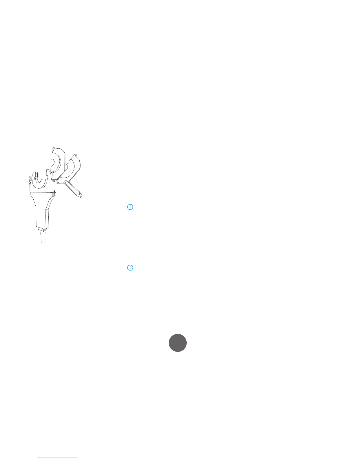
3.8.11 Pass level screens
Pass 1, Level 1
Move the cursor and enter values with the control knob.
• Amps: current at each level (using pulsed current,
this is high pulse current).
• RPM: Rotation Speed
• LP Amps: Low Pulse Amperage, shown as
percentage of high pulse current.
• HPT: High Pulse Time Period, in seconds.
• LPT: Low Pulse Time Period, in seconds.
• HP RPM: rotation speed on high current pulse
(shown only when RPM STEP is turned ON). Can
be set at any percentage from 0–99 of the low
pulse speed listed RPM.
• Level Time: the time during which these
parameters will be active in seconds.
• Time Remaining: as the tube size is input,
selection of RPM automatically calculates Total
(weld) Time.
• Time Remaining: automatically calculated once
Level Time is entered.
• Total Time: total time for weld in seconds. Enter
values and press Next soft key to go to Level 2.
Parameters are automatically carried down through
the levels.
The software of the 150 series controller makes it very easy
to copy parameters from one level to the next by merely
pressing Next.
Be careful when changing parameters at one specic
level to avoid unwanted changes.
Page 26
26
A7 TIG Orbital System 150© Kemppi Oy 2016 1615
OPERATING MANUAL
Example
You wish to change the amperage originally programmed
in Level 4 of a one pass weld. However, other parameter
changes occur in a subsequent level, such as level 5 or 6.
If you make the change in amperage in Level 4 and press
Next, you will automatically copy all of the Program Level
4 values into Level 5. Therefore, note any other changes
that are occurring in subsequent levels within the pass
before modifying any parameter in that pass. This is only
true for Level parameters within any given pass. For a
multi‐pass weld, once you move to a subsequent pass,
the parameters will not be copied from the previous pass.
Pass 1, Level 2
Move the cursor and enter values with the control knob
and press Next, or if no change is necessary, just press
Next.
Pass 1, Level 3 to Final Level
Continue moving through the screens for each level and
change parameters as needed
Page 27

27
A7 TIG Orbital System 150© Kemppi Oy 2016 1615
OPERATING MANUAL
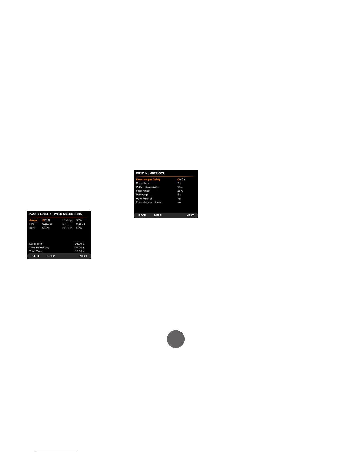
3.8.12 Other screens
Downslope Screen: move the cursor and enter values with
the control knob. Press Next when complete.
Downslope Delay: downslope of weld current will occur
immediately at the tie‐in of the start location. If you
want an overlap of the weld, set the desired seconds of
Downslope Delay.
Downslope: downslope or current taper time period in
seconds.
Pulsing Downslope: choice of pulse current or steady state
current during downslope period (Yes or No).
Final Amps: weld current level just prior to arc termination.
Post‐purge: time period gas ows after arc termination
(seconds).
Auto Rewind: if this feature is “switched on” (by selecting
Yes on the display), it will cause the weld head to
automatically rewind at completion of a weld and come
to a halt at the starting rotational position. Post‐purge will
also occur simultaneously with auto rewind.
Downslope At Home: if this function is left o, program
downslope will occur at the time out (completion) of the
nal level. If this function is turned ON with the control
knob, program downslope will begin exactly as Home
position is actuated. (If starting from Home position, this
will be one 360° revolution, then downslope will still occur
at 360° Home.
This may override level times. For example, if only
one level of 15 seconds is programmed, for a 1 RPM weld
(requiring 60 seconds), the weld will still be made with
downslope at Home, even though there was inadequate
time to complete the weld in the total level times. If the level
times are longer than 360°, then downslope will still occur at
360° Home.
Parameter Override: use cursor to select line, the control
knob to modify.
3.8.13 Override Limit function
You may override any of the pre-programmed values,
but only within the limits that may be dened during
programming. The percentage of override limits can be
individually programmed for each parameter between
0–100 % of the programmed value. You can have sucient
override capacity to compensate for tube t variations, for
example, but to avoid modifying the original program
outside of specied heat input limitations. The override
limits are saved with each weld so that they allow dierent
override values based on which the weld is being run.
Page 28

28
A7 TIG Orbital System 150© Kemppi Oy 2016 1615
OPERATING MANUAL
3.8.14 Maintenance Menu
In the Main Menu screen, press Menu. This will open the
Maintenance Menu screen. Most functions are passwordprotected if this option is selected.
Copy Welds (power source internal memory)
You may want copy an existing weld program as a starting
point for creating a new weld program for a dierent tube
size using the editing feature.
1. In the Maintenance Menu screen, select Copy
Welds and press Enter.
2. Enter the program numbers for source weld and
destination weld, then press Copy.
The Copy function allows you to copy a weld program
within the power source’s internal memory. (For example,
an existing weld number 2 could be copied to weld
number 10, assuming no program number 10 exists.)
The program will not be deleted from weld number 2;
two copies of the program now exist.
When per forming a Copy or Transfer to a destination
program of the same number, the new le does not write
over the existing le. You may delete the existing le or
select an unused destination program number.
Weld numbers 1–99 are les stored in the internal memory
of the power source.
3.8.15 Options Menu
Any changes made on this screen become active
immediately but are lost when the power is switched o. To
maintain changes, press Save after all changes are made on
the screen.
Setting the weld counter
At completion of each weld, the system stores the actual
parameters run and related weld ID number, operator
name, and time and date to print out if necessary. The
weld number sequentially increases by one digit per weld.
You can set/reset the weld counter at any specic number
using the control knob.
Page 29

29
A7 TIG Orbital System 150© Kemppi Oy 2016 1615
OPERATING MANUAL
Setting the password
Press Enter. Password screen appears. Press Enter. An
alphanumeric pop‐up eld appears. Enter a password up
to 10 characters using the technique described in section
Alphanumeric labeling. To conrm password, press Save.
Entering operator’s name
Enter operator’s name using the technique described in
section Alphanumeric labeling.
Setting date and time
Press Enter to select the Date/Time eld and set date and
time.
Setting the language
Use the control knob to scroll through the alternatives.
Setting the units of measure
The control knob lets you scroll between Standard and
Metric.
Using the test mode
If you need to use the test mode, use the control knob to
select Yes.
This mode allows simulation of an actual weld with
sequencing through the weld program and simultaneous
rotation of the weld head. By using this function You can
observe the rotation of the tungsten electrode while
changing the various levels of the program on the display.
It is a useful diagnostic tool if you suspect malfunction
during the weld mode. A service technician can operate
the system in a simulated weld mode without the need to
worry about the arc. In the test mode, the contactor signal
to the power supply is disabled, preventing initiation of
high frequency and a welding arc.
1. Exit the Options menu.
2. Select a program to run. TEST MODE appears on
the screen.
3. Press Start Weld.
Following the pre‐purge and current upslope time
interval, the rotation motor on the weld head becomes
operational. It will continue operation until current
downslope is over. If the Auto Rewind function has been
programmed to occur, it follows after the completion of
the simulated weld. The gas solenoid is pulled in during
pre‐purge, welding, and post‐purge.
Page 30

30
A7 TIG Orbital System 150© Kemppi Oy 2016 1615
OPERATING MANUAL
3.8.16 Copying/transferring files to memory stick
(*These are the actual weld programs, not print les. They
are special le types formatted for the welding control
system, not human-readable les.)
1. To transfer a weld program from internal memory
to a memory stick or vice versa, place the stick in
the USB port on the front of the power source.
The stick will require approximately 1 minute to
initialize, during which time the LCD on the side
of the key will slowly pulse. When it is ready, it will
blink rapidly 5 times.
2. In the Maintenance Menu, select Copy Welds and
press Enter. Enter the desired program numbers
for source weld and destination weld, then press
Copy. For weld programs 100 and above, indicate
a program to be stored (or presently stored) on the
stick.
When per forming a copy or transfer to a destination
program of the same number, the new le does not write
over the existing le. You can delete the existing le or select
an unused destination program number.
Until the stick has nished initializing, a message will
appear on the display “Data Key Not Ready”. If no stick is
installed, ERROR message will also display.
3.8.17 Deleting welds
The Delete function is used to remove unwanted programs
from memory.
1. In the Maintenance Menu, select Delete Welds and
press Enter.
2. Use the control knob to select a weld program.
3. Press Delete.
You can also use this feature to delete welds from a memory
stick if it has been installed and initialized. Program on the
stick is numbered 100 and higher.
Only existing weld programs are displayed in the
Delete screen.
Page 31

31
A7 TIG Orbital System 150© Kemppi Oy 2016 1615
OPERATING MANUAL
3.8.18 Printing welds
On the Print Weld Files screen you can print to the built‐in
paper tape printer and/or an internal memory location.
Printing to the printer provides an immediate hard copy
of the weld program. You can print weld programs to
memory one or more times over a period of time and then
download them to a memory stick for storage or transfer
them to other electronic media. The contents of memory
will be deleted.
1. On the Maintenance Menu, select Print Welds.
2. Select Weld To Print.
3. Using the control knob, enter the weld number to
print.
4. Select Print or Store File.
5. Use the control knob to select: Memory, Printer, or
Both.
6. Select Short Form (parameters only) or Long Form
(parameters, as well as all procedure information
and notes).
7. To save the settings that have been changed on the
Maintenance / Print Weld Files screen, press Save.
Memory Internal memory
Print Transfer les for printing to integrated printer
or transfer to memory stick for printing using
a PC.
Automatic
Printout
If set to Yes, the printout automatically occurs
following each weld.
3.8.20.1 Transferring print les to memory stick
You can use a memory stick to transfer or move les to
a standard PC equipped with a printer for later printout.
1. Select the weld number to transfer and use the
control knob to select Print to Memory, Print, or
Both.
2. Press Print. A screen will state that the weld has
been successfully saved to memory.
3. Save one or more welds to print later. (The memory
stick does not have to be installed at this time.)
To transfer a weld program from internal memory to a
memory stick:
1. Place the stick in the USB por t in the front panel.
2. The stick will require approximately 1 minute to
initialize, at which time the LCD on the side of the
key will slowly pulse.
3. When the stick is ready, the LCD blinks rapidly 5
times.
Page 32

32
A7 TIG Orbital System 150© Kemppi Oy 2016 1615
OPERATING MANUAL
4. If no stick is installed or it has not yet nished
initializing, an error message displays.
5. Press Dnload to download all stored print les to
the stick.
Dnload will delete these programs from memory.
You can open the print les saved on a memor y stick in any
text editor, such as Microsoft® Word, Microsoft® Notepad,
or Microsoft® Excel.
In case you see an error message, return to Main
Menu and re-enter the print screen. “Error” will change to
“Dnload”. If a memory stick is installed and initialized prior
to entering the print screen, this step is not required.
3.8.19 Tungsten electrode length calculator
To determine the optimum cut-length for the tungsten
electrode, refer to this screen. For 800 series weld heads,
tungsten electrode length is calculated based on tube OD.
3.8.20 Advanced Help
Advanced Help allows you to diagnose problems which
may result from an external situation (e.g. an empty
gas bottle) or an internal situation (e.g. the weld head
control cable is damaged or not connected). Advanced
Help provides assistance for the operator as well as for a
competent electric repair technician.
3.8.21 Autotack
Tack welding is useful when welding larger diameter tubes,
for which Autotack automatically generates a tack-welding
program. Select 4 or 8 equally spaced tacks. Tacking
parameters penetrate approximately 70% of the tube wall.
If the intention is to make the weld to immediately follow
tacking, set the welding program as the “Next Weld to Run”
and the program is loaded automatically.
Page 33

33
A7 TIG Orbital System 150© Kemppi Oy 2016 1615
OPERATING MANUAL
4. ADDITIONAL DETAILS
4.1 Technical data
Property Value
Mains connection voltage 230 VAC ± 10%
Fuse (delayed) 16 A
Maximum output current 220 A @ 40 %, 170 A @ 100 %
Weld heads 150 series
Pipe outer diameter (O.D.) 3.2−152.4 mm
Welding positions All
Auto-stop Yes
Type of ignition HF
Cooling (controller unit) Forced air
Cooling (weld head) Internal coolant circulator
Controller external dimensions (L x W x H) 501 x 273 x 670 mm
Weight 32 kg
Degree of protection IP 23
Operating temperature -20…+40 °C
5. ORDERING INFORMATION
The chart below shows the products and options required. A complete orbital welding
system requires an orbital controller, a weld head of suitable size, collets for the weld head
(extended or ush) and cut-to-length tungsten electrodes. There are several additional
pieces of equipment available as listed below to complete a productive orbital welding
environment.
Weld head
Gas purge kit
Oxygen content meter
Dual pressure regulator
Tungsten grinding &
cutting equipment
Electrodes 1.0, 1.6 and 2.4 mm
Extended cables
weld head model 15010
Collets
weld head model 15020
Flush
weld head model 15030
Extended
weld head model 15040
Electrode
weld head model 15060
A7 TIG Orbital Controller 150
Page 34

34
A7 TIG Orbital System 150© Kemppi Oy 2016 1615
OPERATING MANUAL
Product ordering codes:
Product name Product code
A5 TIG Orbital Controller 150 6204150
15010 Orbital weld head 6206002
15020 Orbital weld head 6206003
15030 Orbital weld head 6206004
15040 Orbital weld head 6206005
15060 Orbital weld head 6206006
Tungsten electrode 1.0 mm, L = 175 mm, 10 pc 9873531
Tungsten electrode 1.6 mm, L = 175 mm, 10 pc 9873532
Tungsten electrode 2.4 mm, L = 175 mm, 10 pc 9873533
150 Series Orbital Tungsten Mount Kit 1.0 mm SP800681
150 Series Orbital Tungsten Mount Kit 1.6 mm SP800682
150 Series Orbital Tungsten Mount Kit 2.4 mm SP800683
Extension cable, 15 m A7 TIG Orbital Controller 150 SP800693
Dual ow meter regulator SP800680
Ultima TIG-cut, tungsten electrode cutting/sharpening machine 6270001
Neutrix, portable tungsten electrode sharpening machine 6270002
Auto grind, tungsten electrode automated grinder 6270003
Purge plug kit 10−100 mm 6206009
Oxygen content meter 10−1000 ppm 6206008
Printer paper roll 58 mm
SP800692
Electrode lengths for dierent tube OD, 15010 weld head
Electrode diameter
Tube OD Tube OD 1.0 mm 1.6 mm 2.4 mm
mm inch length [mm] length [mm] length [mm]
3.17 0.125 26.4 25.8 25.3
6 0.236 25.0 24.4 23.9
6.35 0.250 24.8 24.2 23.7
8 0.315 24.0 23.4 22.9
9.53 0.375 23.2 22.6 22.1
10 0.394 23.0 22.4 21.9
10.2 0.402 22.9 22.3 21.8
12 0.472 22.0 21.4 20.9
12.7 0.500 21.6 21.1 20.6
13 0.512 21.5 20.9 20.4
13.5 0.531 21.2 20.7 20.2
15.88 0.625 20.0 19.5 19.0
16 0.630 20.0 19.4 18.9
17.2 0.677 19.4 18.8 18.3
18 0.709 19.0 18.4 17.9
19 0.748 18.5 17.9 17.4
19.05 0.750 18.4 17.9 17.4
20 0.787 18.0 17.4 16.9
21.3 0.839 17.3 16.8 16.3
22 0.866 17.0 16.4 15.9
23 0.906 16.5 15.9 15.4
25.4 1.000 15.3 14.7
14.2
Page 35

35
A7 TIG Orbital System 150© Kemppi Oy 2016 1615
OPERATING MANUAL
Electrode lengths for dierent tube OD, 15020 weld head
Tube OD Tube OD Electrode diameter
1.0 mm 1.6 mm 2.4 mm
mm inch length [mm] length [mm] length [mm]
6.0 0.236 38.3 37.7 37.2
6.4 0.250 38.1 37.6 37.1
8.0 0.315 37.3 36.7 36.2
9.5 0.375 36.5 36.0 35.5
10.0 0.394 36.3 35.7 35.2
10.2 0.402 36.2 35.6 35.1
12.0 0.472 35.3 34.7 34.2
12.7 0.500 34.9 34.4 33.9
13.0 0.512 34.8 34.2 33.7
13.5 0.531 34.5 34.0 33.5
15.9 0.625 33.3 32.8 32.3
16.0 0.630 33.3 32.7 32.2
17.2 0.677 32.7 32.1 31.6
18.0 0.709 32.3 31.7 31.2
19.0 0.748 31.8 31.2 30.7
19.1 0.750 31.8 31.2 30.7
20.0 0.787 31.3 30.7 30.2
21.3 0.839 30.6 30.1 29.6
22.0 0.866 30.3 29.7 29.2
23.0 0.906 29.8 29.2 28.7
25.4 1.000 28.6 28.0 27.5
26.9 1.059 27.8 27.3 26.8
28.0 1.102 27.3 26.7 26.2
29.0 1.142 26.8 26.2 25.7
30.0 1.181 26.3 25.7 25.2
33.7 1.327 24.4 23.9 23.4
35.0 1.378 23.8 23.2 22.7
38.1 1.500 22.2 21.7 21.2
40.0 1.575 21.3 20.7 20.2
41.0 1.614 20.8 20.2 19.7
42.4 1.669 20.1 19.5 19.0
44.5 1.752 19.0 18.5 18.0
48.3 1.902 17.1 16.6 16.1
50.8 2.000 15.9 15.3 14.8
Page 36

36
A7 TIG Orbital System 150© Kemppi Oy 2016 1615
OPERATING MANUAL
Electrode lengths for dierent tube OD, 15030 weld head
Tube OD Tube OD Electrode diameter
1.0 mm 1.6 mm 2.4 mm
mm inch length [mm] length [mm] length [mm]
9.5 0.375 49.1 48.5 48.0
10.0 0.394 48.9 48.3 47.8
10.2 0.402 48.8 48.2 47.7
12.0 0.472 47.9 47.3 46.8
12.7 0.500 47.5 47.0 46.5
13.0 0.512 47.4 46.8 46.3
13.5 0.531 47.1 46.6 46.1
15.9 0.625 45.9 45.4 44.9
16.0 0.630 45.9 45.3 44.8
17.2 0.677 45.3 44.7 44.2
18.0 0.709 44.9 44.3 43.8
19.0 0.748 44.4 43.8 43.3
19.1 0.750 44.3 43.8 43.3
20.0 0.787 43.9 43.3 42.8
21.3 0.839 43.2 42.7 42.2
22.0 0.866 42.9 42.3 41.8
23.0 0.906 42.4 41.8 41.3
Tube OD Tube OD electrode diameter
1.0 mm 1.6 mm 2.4 mm
mm inch length [mm] length [mm] length [mm]
25.4 1.000 41.2 40.6 40.1
26.9 1.059 40.4 39.9 39.4
28.0 1.102 39.9 39.3 38.8
29.0 1.142 39.4 38.8 38.3
30.0 1.181 38.9 38.3 37.8
33.7 1.327 37.0 36.5 36.0
35.0 1.378 36.4 35.8 35.3
38.1 1.500 34.8 34.3 33.8
40.0 1.575 33.9 33.3 32.8
41.0 1.614 33.4 32.8 32.3
42.4 1.669 32.7 32.1 31.6
44.5 1.752 31.6 31.1 30.6
48.3 1.902 29.7 29.2 28.7
50.8 2.000 28.5 27.9 27.4
51.0 2.008 28.4 27.8 27.3
52.0 2.047 27.9 27.3 26.8
53.0 2.087 27.4 26.8 26.3
54.0 2.126 26.9 26.3 25.8
60.3 2.374 23.7 23.2 22.7
63.5 2.500 22.1 21.6 21.1
70.0 2.756 18.9 18.3 17.8
76.1 2.996 15.8 15.3 14.8
76.2 3.000 15.8 15.2 14.7
Page 37

37
A7 TIG Orbital System 150© Kemppi Oy 2016 1615
OPERATING MANUAL
Electrode lengths for dierent tube OD, 15040 weld head
Tube OD Tube OD electrode diameter
1.0 mm 1.6 mm 2.4 mm
mm inch length [mm] length [mm] length [mm]
12.0 0.472 60.1 59.5 59.0
12.7 0.500 59.7 59.2 58.7
13.0 0.512 59.6 59.0 58.5
13.5 0.531 59.3 58.8 58.3
15.9 0.625 58.1 57.6 57.1
16.0 0.630 58.1 57.5 57.0
17.2 0.677 57.5 56.9 56.4
18.0 0.709 57.1 56.5 56.0
19.0 0.748 56.6 56.0 55.5
19.1 0.750 56.5 56.0 55.5
20.0 0.787 56.1 55.5 55.0
21.3 0.839 55.4 54.9 54.4
22.0 0.866 55.1 54.5 54.0
23.0 0.906 54.6 54.0 53.5
25.4 1.000 53.4 52.8 52.3
26.9 1.059 52.6 52.1 51.6
28.0 1.102 52.1 51.5 51.0
29.0 1.142 51.6 51.0 50.5
30.0 1.181 51.1 50.5 50.0
33.7 1.327 49.2 48.7 48.2
35.0 1.378 48.6 48.0 47.5
38.1 1.500 47.0 46.5 46.0
40.0 1.575 46.1 45.5 45.0
41.0 1.614 45.6 45.0 44.5
42.4 1.669 44.9 44.3 43.8
44.5 1.752 43.8 43.3 42.8
Tube OD Tube OD electrode diameter
1.0 mm 1.6 mm 2.4 mm
mm inch length [mm] length [mm] length [mm]
48.3 1.902 41.9 41.4 40.9
50.8 2.000 40.7 40.1 39.6
51.0 2.008 40.6 40.0 39.5
52.0 2.047 40.1 39.5 39.0
53.0 2.087 39.6 39.0 38.5
54.0 2.126 39.1 38.5 38.0
60.3 2.374 35.9 35.4 34.9
63.5 2.500 34.3 33.8 33.3
70.0 2.756 31.1 30.5 30.0
76.1 2.996 28.0 27.5 27.0
76.2 3.000 28.0 27.4 26.9
85.0 3.346 23.6 23.0 22.5
88.9 3.500 21.6 21.1 20.6
101.6 4.000 15.3 14.7
14.2
Page 38

38
A7 TIG Orbital System 150© Kemppi Oy 2016 1615
OPERATING MANUAL
Electrode lengths for dierent tube OD, 15060 weld head
Tube OD Tube OD electrode diameter
1.0 mm 1.6 mm 2.4 mm
mm inch length [mm] length [mm] length [mm]
50.8 2.000 74.4 73.9 73.4
51.0 2.008 74.3 73.8 73.3
52.0 2.047 73.8 73.3 72.8
53.0 2.087 73.3 72.8 72.3
54.0 2.126 72.8 72.3 71.8
60.3 2.374 69.7 69.1 68.6
63.5 2.500 68.1 67.5 67.0
70.0 2.756 64.8 64.3 63.8
76.1 2.996 61.8 61.2 60.7
76.2 3.000 61.7 61.2 60.7
85.0 3.346 57.3 56.8 56.3
88.9 3.500 55.4 54.8 54.3
101.6 4.000 49.0 48.5 48.0
104.0 4.094 47.8 47.3 46.8
108.0 4.252 45.8 45.3 44.8
114.3 4.500 42.7 42.1 41.6
127.0 5.000 36.3 35.8 35.3
129.0 5.079 35.3 34.8 34.3
139.7 5.500 30.0 29.4 28.9
152.4 6.000 23.6 23.1 22.6
5.1.1 Collets
When ordering collets, it is important to specify the exact OD dimension of the tube or
tting. Because of the wide range of tting manufacturers, it is necessary to specify the
tting manufacturer and type. If possible, include data sheet or drawing dening the
specication for the tting in the order.
Each tting manufacturer has dierent tolerances on the dimensions of the ttings.
Several tting manufacturers have special product lines specically designed for orbital
welding.
Collets for each type of weld head are specied by:
• Weld head model
• Tube/pipe OD
• Flush or extended
The ordering codes in the above list are per pair of collets. One weld head requires two
pairs.
Page 39

39
A7 TIG Orbital System 150© Kemppi Oy 2016 1615
OPERATING MANUAL
Collet product codes for 15010 weld head
Tube OD
(inch)
Collet,
Extended
Collet, Flush Tube OD
(mm)
Collet,
Extended
Collet, Flush
0.125 1001227-0.125 1001232-0.125 6.0 1001234-6 1001236-6
0.250 1001227-0.25 1001232-0.25 8.0 1001234-8 1001236-8
0.375 1001227-0.375 1001232-0.375 10.0 1001234-10 1001236-10
0.402 1001227-0.402 1001232-0.402 12.0 1001234-12 1001236-12
0.500 1001227-0.500 1001232-0.500 13.0 1001234-13 1001236-13
0.625 1001227-0.625 1001232-0.625 13.5 1001234-13.5 1001236-13.5
0.677 1001227-0.667 1001232-0.667 16.0 1001234-16 1001236-16
0.750 1001227-0.750 1001232-0.750 18.0 1001234-18 1001236-18
0.839 1001227-0.839 1001232-0.839 19.0 1001234-19 1001236-19
1.000 1001227-1.00 1001232-1.00 20.0 1001234-20 1001236-20
22.0 1001234-22 1001236-22
23.0 1001234-23 1001236-23
Collet product codes for 15020 weld head
Tube OD
(inch)
Collet,
Extended
Collet, Flush Tube OD
(mm)
Collet,
Extended
Collet, Flush
0.250 1001238-0.250 1001240-0.250 6.0 1001242-6 1001244-6
0.375 1001238-0.375 1001240-0.375 8.0 1001242-8 1001244-8
0.402 1001238-0.402 1001240-0.402 10.0 1001242-10 1001244-10
0.500 1001238-0.500 1001240-0.500 12.0 1001242-12 1001244-12
0.625 1001238-0.625 1001240-0.625 13.0 1001242-13 1001244-13
0.677 1001238-0.677 1001240-0.677 13.5 1001242-13.5 1001244-13.5
0.750 1001238-0.750 1001240-0.750 16.0 1001242-16 1001244-16
0.839 1001238-0.839 1001240-0.839 18.0 1001242-18 1001244-18
1.000 1001238-1.00 1001240-1.00 19.0 1001242-19 1001244-19
1.327 1001238-1.327 1001240-1.327 20.0 1001242-20 1001244-20
1.500 1001238-1.50 1001240-1.50 22.0 1001242-22 1001244-22
1.669 1001238-1.669 1001240-1.669 23.0 1001242-23 1001244-23
1.902 1001238-1.902 1001240-1.902 26.9 1001242-26.9 1001244-26.9
2.000 1001238-2.00 1001240-2.00 28.0 1001242-28 1001244-28
29.0 1001242-29 1001244-29
30.0 1001242-30 1001244-30
35.0 1001242-35 1001244-35
40.0 1001242-40 1001244-40
41.0 1001242-41 1001244-41
44.5 1001242-44.5 1001244-44.5
Page 40

40
A7 TIG Orbital System 150© Kemppi Oy 2016 1615
OPERATING MANUAL
Collet product codes for 15030 weld head
Tube OD
(inch)
Collet,
Extended
Collet, Flush Tube OD
(mm)
Collet,
Extended
Collet, Flush
0.375 1001246-0.375 1001248-0.375 10 1001250-10 1001252-10
0.402 1001246-0.402 1001248-0.402 12.0 1001250-12 1001252-12
0.500 1001246-0.500 1001248-0.500 13.0 1001250-13 1001252-13
0.625 1001246-0.625 1001248-0.625 13.5 1001250-13.5 1001252-13.5
0.677 1001246-0.677 1001248-0.677 16.0 1001250-16 1001252-16
0.750 1001246-0.750 1001248-0.750 18.0 1001250-18 1001252-18
0.839 1001246-0.839 1001248-0.839 19.0 1001250-19 1001252-19
1.000 1001246-1.327 1001248-1.327 20.0 1001250-20 1001252-20
1.327 1001246-1.327 1001248-1.327 22.0 1001250-22 1001252-22
1.500 1001246-1.500 1001248-1.500 23.0 1001250-23 1001252-23
1.669 1001246-1.669 1001248-1.669 26.9 1001250-26.9 1001252-26.9
1.902 1001246-1.902 1001248-1.902 28.0 1001250-28 1001252-28
2.000 1001246-2.00 1001248-2.00 29.0 1001250-29 1001252-29
2.500 1001246-2.500 1001248-2.500 30.0 1001250-30 1001252-30
3.000 1001246-3.00 1001248-3.00 35.0 1001250-35 1001252-35
40.0 1001250-40 1001252-40
41.0 1001250-41 1001252-41
44.5 1001250-44.5 1001252-44.5
51.0 1001250-51 1001252-51
52.0 1001250-52 1001252-52
53.0 1001250-53 1001252-53
54.0 1001250-54 1001252-54
60.3 1001250-60.3 1001252-60.3
70.0 1001250-70 1001252-70
76.1 1001250-76.1 1001252-76.1
Collet product codes for 15040 weld head
Tube OD
(inch)
Collet,
Extended
Collet, Flush Tube OD
(mm)
Collet,
Extended
Collet, Flush
0.500 1001254-0.500 1001256-0.500 12.0 1001258-12 1001260-12
0.625 1001254-0.625 1001256-0.625 13.0 1001258-13 1001260-13
0.677 1001254-0.677 1001256-0.677 13.5 1001258-13.5 1001260-13.5
0.750 1001254-0.750 1001256-0.750 16.0 1001258-16 1001260-16
0.839 1001254-0.839 1001256-0.839 18.0 1001258-18 1001260-18
1.000 1001254-1.00 1001256-1.00 19.0 1001258-19 1001260-19
1.327 1001254-1.327 1001256-1.327 20.0 1001258-20 1001260-20
1.500 1001254-1.500 1001256-1.500 22.0 1001258-22 1001260-22
1.669 1001254-1.669 1001256-1.669 23.0 1001258-23 1001260-23
1.902 1001254-1.902 1001256-1.902 26.9 1001258-26.9 1001260-26.9
2.000 1001254-2.000 1001256-2.000 28.0 1001258-28 1001260-28
2.500 1001254-2.500 1001256-2.500 29.0 1001258-29 1001260-29
3.000 1001254-3.000 1001256-3.000 30.0 1001258-30 1001260-30
3.500 1001254-3.500 1001256-3.500 35.0 1001258-35 1001260-35
4.000 1001254-4.000 1001256-4.000 40.0 1001258-40 1001260-40
41.0 1001258-41 1001260-41
44.5 1001258-44.5 1001260-44.5
51.0 1001258-51 1001260-51
52.0 1001258-52 1001260-52
53.0 1001258-53 1001260-53
54.0 1001258-54 1001260-54
60.3 1001258-60.3 1001260-60.3
70.0 1001258-70 1001260-70
76.1 1001258-76.1 1001260-76.1
85.0 1001258-85 1001260-85
Page 41

41
A7 TIG Orbital System 150© Kemppi Oy 2016 1615
OPERATING MANUAL
Collet product codes for 15060 weld head
Tube OD
(inch)
Collet,
Extended
Collet, Flush Tube OD
(mm)
Collet,
Extended
Collet, Flush
2.000 1001262-2.000 1001264-2.000 6.0 1001266-51 1001268-51
2.500 1001262-2.500 1001264-2.500 8.0 1001266-52 1001268-52
3.000 1001262-3.00 1001264-3.00 10 1001266-53 1001268-53
3.500 1001262-3.500 1001264-3.500 12.0 1001266-54 1001268-54
4.000 1001262-4.000 1001264-4.000 13.0 1001266-60.3 1001268-60.3
4.500 1001262-4.500 1001264-4.500 13.5 1001266-70 1001268-70
5.000 1001262-5.000 1001264-5.000 16.0 1001266-76.1 1001268-76.1
5.500 1001262-5.500 1001264-5.500 18.0 1001266-85 1001268-85
6.000 1001262-6.000 1001264-6.000 19.0 1001266-104 1001268-104
20.0 1001266-108 1001268-108
22.0 1001266-127 1001268-127
23.0 1001266-129 1001268-129
5.1.2 Tungsten electrode material
Kemppi uses ceriated tungsten to increase electrode life,
arc starting, and stability, and recommends this material
for orbital use.
2% ceriated = no radiation risk
These tungsten electrodes are commonly marked in grey
color.
Ordering codes for standard length (175 mm) tungsten
electrodes and sharpening / cutting machines:
9873531 10 pcs. 1.0 mm diameter, 175 mm long
9873532 10 pcs. 1.6 mm diameter, 175 mm long
9873533 10 pcs. 2.4 mm diameter, 175 mm long
6270001 Ultima – TIG – cut, tungsten electrode cutting/sharpening machine
6270002 Neutrix, portable, tungsten electrode sharpening machine
6270003 Auto Grind, Tungsten electrode automated grinder.
Page 42

42
A7 TIG Orbital System 150© Kemppi Oy 2016 1615
OPERATING MANUAL
6. TROUBLESHOOTING
6.1 Operation problems
Should you experience a malfunction from your machine, please consult the troubleshooting sections below rst, and complete some basic checks.
If the machine malfunction cannot be corrected with these measures, contact your
Kemppi maintenance service workshop.
The problems listed and the possible causes are not denitive but serve to suggest
some standard and typical situations that may present during normal environmental use
when using the A7 TIG Orbital System 150.
Problem: Check the following:
Machine won’t work • Check that mains plug is connected correctly.
• Check that mains power distribution is switched on.
• Check the mains fuse and or circuit breaker.
• Check that power source 0/I switch is ON.
• Check that interconnection cable set and connectors
between the power source and weld head unit are
correctly fastened. See Installation section of this manual.
Dirty, poor quality weld • Check shielding gas supply.
• Check and set gas ow rate.
• Check that correct welding program is selected.
• Check correct selection on the control panel.
Variable welding
performance
• Check welding parameter settings.
6.2 Tungsten electrode rotation not concentric to tube O.D.
The tungsten electrode should maintain an equal gap ±0.1mm (±0.005") Total Indicated
Runout (T.I.R.) as it rotates around the workpiece. Variations of arc gap outside this
tolerance will cause inconsistent penetration and weld bead width.
• Collets are sized to plus .075mm (.003”) over tube diameter to allow production
tolerance on tubing.
• Deviation of more than ± .05mm (.002”0) will cause tubing to be o-centre by
more than the allowed .1mm, which will result in an inconsistent penetration and
weld bead width.
• Collets should be specied to ± .5mm when ordered.
The "wheel base" of the collets determines how squarely the weld head clamps on the two
tubes and how much "squaring" capability it has.
• If two long runs of tube are not parallel and standard collets are being used, the
weld head cannot bring the two long lengths of tube into perfect alignment.
Therefore, there will be a run-out as the tungsten electrode rotates around the
tube ends.
• Correct this by using external alignment clamp or by using extended collets.
Page 43

43
A7 TIG Orbital System 150© Kemppi Oy 2016 1615
OPERATING MANUAL
Problem Possible solution
Arcing within the
weld head (see
Maintenance section)
Contaminated eroded or improper length tungsten electrode.
• Improperly cleaned tube surface or poor contact between collets
and tube may cause arcing between tube/pipe collets.
• Metal debris on the inside surface of the weld head.
• Arc-star ting amperage too low.
High frequency but no
weld current
Check for broken electrode or ground cable in the weld head, handle,
or in the cable.
Defects in butt welds
Lack of penetration
with work piece in
5G (horizontal) or 2G
(vertical) positions
• Insucient current
• Rotation speed too high
• Contaminated gas, insucient gas or wrong gas
• Arc gap too great, wrong tungsten tip conguration or
Contaminated/worn tungsten electrode
• Gas ow too high
• Arc not on the joint
• Tube wall dimensional variation
• End of tube not square
• Too much gas on I.D. or no I.D. purge
• Tubes not cleaned
ID location • Increase rotation delay or increase Level 1 amps
• Increase weld current or decrease weld head speed
• Use next weld level 2 to increase amps
• Downslope star ting too soon; increase time at last level or use Start
position to initiate downslope.
Concavity (suckback) or excessive
penetration
• All ID locations
• Weld current too high
• Rotation speed too low
• Tubes not tightly butted together
• Tubes ends not square
• ID purge gas pressure too high; create larger gas exit hole
Over-penetration General
Most common through the 12 o’clock position in 5G (tube horizontal)
welding
• Increase rotation speed
• Decrease weld current
• Contaminated or improper gas
• Gas ow too high
• Tungsten arc gap may have changed or tungsten conguration has
changed
• Weld head not in calibration
• Tubes not tightly butted
• Tube ends not square
ID location
• Rotation delay period too long, too much weld current or
• Rotation too low
• Increase speed or decrease current
• Current too high in weld level or may need to change to another
level with reduction in current
• Increase rotation delay or increase Level 1 amps
• Increase weld current or decrease Head speed
• Use next weld Level 2 to increase amps
• Downslope star ting too soon; increase time at last level or use Start
position to initiate downslope
Porosity or improper
gas coverage
• Contaminated gas or improper gas
• Oil, dirt or other contaminant on tube ID/OD.
Hole in gas line aspirating air.
• Pre-purge/postpurge time too short
• Poor welding tube alloy
• Gas ow rate ID or OD too low
Page 44

44
A7 TIG Orbital System 150© Kemppi Oy 2016 1615
OPERATING MANUAL
7. MAINTENANCE
When considering and planning routine maintenance,
please consider the frequency of machine use and the
working environment.
Correct operation of the machine and regular maintenance
will help you avoid unnecessary downtime and equipment
failure.
Disconnect the machine from the mains before
handling the electrical cables.
7.1 Periodic maintenance
Periodic maintenance should only be carried out by
a suitably qualied person. Disconnect the plug of the
machine from the mains socket and wait about 2 minutes
(capacitor charge) before removing any parts.
Check at least every half year:
• Electric connectors of the machine – clean any
oxidized parts and tighten loose connections.
Do not use compressed air for cleaning as there is a
risk that the dirt will compact even more tightly into gaps of
cooling proles.
Do not use pressure washing devices.
Only an authorized trained electrician should carry out
repairs to Kemppi machines.
7.1.1 Factory and field calibration
Kemppi calibrates each system using instrumentation
traceable according to ISO 9001. All instruments are
checked for accuracy by independent laboratories at
scheduled intervals. We recommend that equipment is
recalibrated every twelve (12) months. You may recalibrate
the power source and weld heads if proper instruments
are available (with traceable calibration). Contact the
factory if necessary.
7.2 Weld head maintenance
7.2.1 Calibrating the weld head
The 150 series controller software allows users to calibrate
the travel speed for 150 series of weld heads. Weld heads
supported by the 150 series controller software utilize
built‐in encoders for motor control while some others may
use a tachometer. The encoder‐based heads oer better
control of the travel, and therefore little or no adjustment
is required during the calibration process. Tachometer‐
based heads usually require adjustment each time they
are calibrated.
Kemppi recommends that the travel speed are checked
once daily to ensure accuracy.
To calibrate the head, press Menu in the Main menu to
enter the Maintenance menu. Once in the Calibrate Head
menu, do the following:
1. Select the model of the weld head to be calibrated.
2. Use Up/Down to navigate within the menu and
Enter to make a selection.
3. If this is the rst time calibrating a particular weld
head or you see “Calibration Out of Range” error
message, press Default after selecting the weld
head to install the factory setting for the correction
factor.
4. Select Travel Speed to calibrate.
5. For travel calibrations, choose the Distance to
Trav el or Desired RPM by rotating the dial and press
Enter.
6. Press Run and measure the actual amount traveled
or actual run time (or the length of wire).
7. Enter the measured value and press Save.
8. Repeat this process until you have achieved
desired accuracy, then press Back to return to the
Maintenance menu.
Page 45

45
A7 TIG Orbital System 150© Kemppi Oy 2016 1615
OPERATING MANUAL
7.2.2 Cleaning the weld head
Clean the weld head periodically to maintain maximum
operating eciency. Keep the unit free of moisture, debris,
and other contaminants (oil, water, abrasives, etc.) that can
aect normal operation and weld consistency.
• Clean insulating components with a soft brush
and a fast drying solvent, such as acetone or
denatured alcohol.
• Clean drive gear assemblies using a ne wire
brush and solvent. Inspect the drive gear, bevel
gear, and rotor assembly to insure that debris
have not damaged the rotor sprocket lobes and
aected the operation of the drive assembly. Use
a ne jeweler’s le to repair light.
• Clean the body with a cloth or soft brush and
solvent.
• Clean the collets with ne stainless steel wool or
ne wire brush.
Only use stainless steel, as regular carbon steel will ruin
the surface passivation. All parts must be completely dry
before reassembly.
Dirt and impurities in the weld head may cause internal
arcing. It is a situation where the arc jumps from the
tungsten electrode to the collet frame and the welding
arc fails to ignite.
7.2.3 Internal arcing
When internal arcing happens, a track of carbon is left on
the dielectric material, which may cause the same problem
to happen again.
To prevent internal arcing, do the following:
• Periodically clean the weld head according to
instructions given above in section “Cleaning the
weld head”.
• Maintain the tungsten electrode in good working
condition at all times.
Remember that the collet frame and collets are connected
to the ground cable and act as the ground contact for the
electrical circuit.
If internal arcing does occur, do the following:
• Carefully scrape all burn marks from the plastic
body with a razor blade or other sharp scraping
tool.
• Remove all carbon and polish with a ne wire
brush.
• Remove all carbon o the collet frame and collets
with a ne wire brush.
• Remove the rotor gear and polish if necessary
with a ne wire brush to remove any traces of
arcing.
• Clean with alcohol or other suitable solvent and a
lint free cloth before reassembling.
Page 46

46
A7 TIG Orbital System 150© Kemppi Oy 2016 1615
OPERATING MANUAL
7.3 Printer operation and maintenance
The printer is mounted in the front panel of the control
unit to print program parameters and other data. The
printouts remain stable for ve (5) years, and they can be
archived if suitably stored. This printer uses Thermal Paper
P/N SP800692.
7.3.1 Installing paper in the printer
To install paper in the printer, do the following:
1. Open the hinged plastic cover over the paper roll.
2. Remove the empty roll.
3. Replace with a new roll oriented so that the paper
is feeding o the bottom of the roll.
4. Lower the plastic cover until it “clicks”.
7.3.2 Cleaning the printer
You can clean the surface of the printer using a soft dry
cloth or a soft cloth with a neutral detergent. Do not clean
using any solvents. Never wet the inside of the printer.
7.4 Updating software
The 150 series controller allows complete software
upgrade via memory stick or thumb‐drive. This software
can be downloaded from the Kemppi datastore as an email
attachment. Please contact Kemppi’s service department
for upgrade information. Please have the serial number
of your unit, the software release number, and the core
version number handy.
7.5 Service Workshop maintenance
Kemppi Service Workshops complete maintenance
according to their Kemppi service agreement.
The major points in the maintenance procedure are listed
as follows:
• Cleaning of the machine
• Checking and maintenance of the welding tools
• Checking of connectors, switches and
potentiometers
• Checking of electric connections
• Checking of mains cable and plug
• Damaged parts or parts in bad condition are
replaced by new ones
• Maintenance testing.
• Operation and performance values of the
machine are checked, and when necessary
adjusted by means of software and test
equipment.
Software loading
Kemppi Service Workshops can also test and load rmware
and welding software.
Page 47

47
A7 TIG Orbital System 150© Kemppi Oy 2016 1615
OPERATING MANUAL
8. DISPOSAL
Do not dispose of electrical equipment with normal waste!
In observance of European Directive 2002/96/EC on
waste electrical and electronic equipment, and its
implementation in accordance with national law,
electrical equipment that has reached the end of its life
must be collected separately and taken to an appropriate
environmentally responsible recycling facility.
The owner of the equipment is obliged to deliver a
decommissioned unit to a regional collection centre,
as per the instructions of local authorities or a Kemppi
representative. By applying this European Directive you
will improve the environment and human health.
Page 48

And you know.
 Loading...