

Page 1

www.keithley.com
Automated Characterization Suite (ACS)
Basic Edition
Reference Manual
ACSBASIC-901-01 Rev. E / August 2012
*PACSBASIC90101*
ACSBASIC-901-01
ECNEDIFNOC FO ERUSAEM RETAERG A
Page 2

Automated Characterization Suite (ACS)
Basic Edition
Reference Manual
© 2008-2012, Keithley Instruments, Inc.
Cleveland, Ohio, U.S.A.
All rights reserved.
Any unauthorized reproduction, photocopy, or use the information herein, in whole or in part,
without the prior written approval of Keithley Instruments, Inc. is strictly prohibited.
All Keithley Instruments product names are trademarks or registered trademarks of Keithley
Instruments, Inc. Other brand names are trademarks or registered trademarks of their respective holders.
The Lua 5.0 software and associated documentation files are copyright © 1994-2008, Tecgraf,
PUC-Rio. Terms of license for the Lua software and associated documentation can be accessed at the
Lua licensing site (http://www.lua.org/license.html).
Keithley's standard terms and conditions of sale in effect at the time of acceptance of buyer's order by Keithley
shall apply to all purchase of goods and performance of services from Keithley, to the exclusion of any additional
or different terms and conditions, including any terms or conditions which buyer may purport to apply under any
buyer's request for quotation, purchase order or similar document, or which buyer may offer in response to these
terms. A copy of Keithley's current terms can be accessed at
http://www.keithley.com/company/termsandconditions (these "Terms"). To obtain a printed copy of these Terms,
please contact your local sales office or send an email to [email protected]. Buyer's assent to these Terms,
and only these Terms, shall be conclusively presumed from buyer's acceptance of delivery of the products and/or
services provided by Keithley.
Document number: ACSBASIC-901-01 Rev. E / August 2012
Page 3

Safety Precautions
The following safety precautions should be observed before using this product and any associated instrumentation. Although
some instruments and accessories would normally be used with nonhazardous voltages, there are situations where hazardous
conditions may be present.
This product is intended for use by qualified personnel who recognize shock hazards and are familiar with the safety precautions
required to avoid possible injury. Read and follow all installation, operation, and maintenance information carefully before using
the product. Refer to the user documentation for complete product specifications.
If the product is used in a manner not specified, the protection provided by the product warranty may be impaired.
The types of product users are:
Responsible body is the individual or group responsible for the use and maintenance of equipment, for ensuring that the
equipment is operated within its specifications and operating limits, and for ensuring that operators are adequately trained.
Operators use the product for its intended function. They must be trained in electrical safety procedures and proper use of the
instrument. They must be protected from electric shock and contact with hazardous live circuits.
Maintenance personnel perform routine procedures on the product to keep it operating properly, for example, setting the line
voltage or replacing consumable materials. Maintenance procedures are described in the user documentation. The procedures
explicitly state if the operator may perform them. Otherwise, they should be performed only by service personnel.
Service personnel are trained to work on live circuits, perform safe installations, and repair products. Only properly trained
service personnel may perform installation and service procedures.
Keithley Instruments products are designed for use with electrical signals that are rated Measurement Category I and
Measurement Category II, as described in the International Electrotechnical Commission (IEC) Standard IEC 60664. Most
measurement, control, and data I/O signals are Measurement Category I and must not be directly connected to mains voltage or
to voltage sources with high transient overvoltages. Measurement Category II connections require protection for high transient
overvoltages often associated with local AC mains connections. Assume all measurement, control, and data I/O connections are
for connection to Category I sources unless otherwise marked or described in the user documentation.
Exercise extreme caution when a shock hazard is present. Lethal voltage may be present on cable connector jacks or test
fixtures. The American National Standards Institute (ANSI) states that a shock hazard exists when voltage levels greater than
30 V RMS, 42.4 V peak, or 60 VDC are present. A good safety practice is to expect that hazardous voltage is present in any
unknown circuit before measuring.
Operators of this product must be protected from electric shock at all times. The responsible body must ensure that operators
are prevented access and/or insulated from every connection point. In some cases, connections must be exposed to potential
human contact. Product operators in these circumstances must be trained to protect themselves from the risk of electric shock. If
the circuit is capable of operating at or above 1000 V, no conductive part of the circuit may be exposed.
Do not connect switching cards directly to unlimited power circuits. They are intended to be used with impedance-limited
sources. NEVER connect switching cards directly to AC mains. When connecting sources to switching cards, install protective
devices to limit fault current and voltage to the card.
Before operating an instrument, ensure that the line cord is connected to a properly-grounded power receptacle. Inspect the
connecting cables, test leads, and jumpers for possible wear, cracks, or breaks before each use.
When installing equipment where access to the main power cord is restricted, such as rack mounting, a separate main input
power disconnect device must be provided in close proximity to the equipment and within easy reach of the operator.
For maximum safety, do not touch the product, test cables, or any other instruments while power is applied to the circuit under
test. ALWAYS remove power from the entire test system and discharge any capacitors before: connecting or disconnecting
cables or jumpers, installing or removing switching cards, or making internal changes, such as installing or removing jumpers.
Do not touch any object that could provide a current path to the common side of the circuit under test or power line (earth)
ground. Always make measurements with dry hands while standing on a dry, insulated surface capable of withstanding the
voltage being measured.
The instrument and accessories must be used in accordance with its specifications and operating instructions, or the safety of
the equipment may be impaired.
11/07
Page 4

Do not exceed the maximum signal levels of the instruments and accessories, as defined in the specifications and operating
information, and as shown on the instrument or test fixture panels, or switching card.
When fuses are used in a product, replace with the same type and rating for continued protection against fire hazard.
Chassis connections must only be used as shield connections for measuring circuits, NOT as safety earth ground connections.
If you are using a test fixture, keep the lid closed while power is applied to the device under test. Safe operation requires the use
of a lid interlock.
If a
screw is present, connect it to safety earth ground using the wire recommended in the user documentation.
The
the user documentation in all cases where the symbol is marked on the instrument.
The
contact with these voltages.
The symbol on an instrument shows that the surface may be hot. Avoid personal contact to prevent burns.
The
If this symbol is on a product, it indicates that mercury is present in the display lamp. Please note that the lamp must be
properly disposed of according to federal, state, and local laws.
The WARNING heading in the user documentation explains dangers that might result in personal injury or death. Always read
the associated information very carefully before performing the indicated procedure.
The CAUTION heading in the user documentation explains hazards that could damage the instrument. Such damage may
invalidate the warranty.
Instrumentation and accessories shall not be connected to humans.
Before performing any maintenance, disconnect the line cord and all test cables.
To maintain protection from electric shock and fire, replacement components in mains circuits — including the power
transformer, test leads, and input jacks — must be purchased from Keithley Instruments. Standard fuses with applicable national
safety approvals may be used if the rating and type are the same. Other components that are not safety-related may be
purchased from other suppliers as long as they are equivalent to the original component (note that selected parts should be
purchased only through Keithley Instruments to maintain accuracy and functionality of the product). If you are unsure about the
applicability of a replacement component, call a Keithley Instruments office for information.
symbol on an instrument means caution, risk of danger. The user should refer to the operating instructions located in
symbol on an instrument means caution, risk of electric shock. Use standard safety precautions to avoid personal
symbol indicates a connection terminal to the equipment frame.
To clean an instrument, use a damp cloth or mild, water-based cleaner. Clean the exterior of the instrument only. Do not apply
cleaner directly to the instrument or allow liquids to enter or spill on the instrument. Products that consist of a circuit board with
no case or chassis (e.g., a data acquisition board for installation into a computer) should never require cleaning if handled
according to instructions. If the board becomes contaminated and operation is affected, the board should be returned to the
factory for proper cleaning/servicing.
11/07
Page 5

Table of Contents
ACS Basic introduction ............................................................................................ 1-1
ACS Basic software overview ................................................................................................... 1-1
Reference manual content ........................................................................................................ 1-2
ACS Basic software introduction ............................................................................ 2-1
Pre-installation software requirements ...................................................................................... 2-1
Software installation .................................................................................................................. 2-2
ACS Basic software overview .................................................................................. 3-1
Before starting ACS Basic ......................................................................................................... 3-1
ACS Basic USB license key ...................................................................................................... 3-2
Operating modes ....................................................................................................................... 3-5
Account management ............................................................................................................... 3-8
ACS Basic GUI ........................................................................................................................ 3-13
ACS Basic hardware configuration ......................................................................... 4-1
Introduction ............................................................................................................................... 4-1
Configure hardware function ..................................................................................................... 4-2
Supported communication interfaces ........................................................................................ 4-3
Connect to a single instrument .................................................................................................. 4-3
Connect to multiple instruments ................................................................................................ 4-9
Connect to Model 4200-SCS SMUs ........................................................................................ 4-14
Connect to external instruments .............................................................................................. 4-18
View and setup instrument properties ..................................................................................... 4-22
Save the hardware configuration ............................................................................................. 4-37
Check the hardware configuration ........................................................................................... 4-37
Configure the hardware in demo mode ................................................................................... 4-38
ACS Basic test setup ................................................................................................ 5-1
Test setup introduction .............................................................................................................. 5-1
Single-test mode ....................................................................................................................... 5-4
Multi-test mode ........................................................................................................................ 5-10
Trace mode ............................................................................................................................. 5-15
Data plot .................................................................................................................................. 5-24
Advanced operations .............................................................................................................. 5-45
ACS Basic test modules ........................................................................................... 6-1
Configure a graphical interactive test module (ITM) .................................................................. 6-1
Configure a script test module (STM) ...................................................................................... 6-33
Configure a python test module (PTM) ................................................................................... 6-51
ACS Basic script editor tool ..................................................................................... 7-1
Introduction ............................................................................................................................... 7-1
Script Editor GUI ....................................................................................................................... 7-2
Script Editor tutorials ............................................................................................................... 7-12
Page 6

Table of Contents
Reference Manual
ACS Basic Automated Characterization Suite
Formulator function reference ................................................................................. 8-1
ABS ........................................................................................................................................... 8-2
AT ............................................................................................................................................. 8-2
AVG .......................................................................................................................................... 8-2
CURRENT NOISE .................................................................................................................... 8-3
DELTA ...................................................................................................................................... 8-3
DIFF .......................................................................................................................................... 8-3
DIMENSION .............................................................................................................................. 8-3
EXP ........................................................................................................................................... 8-4
EXPFIT ..................................................................................................................................... 8-4
EXPFITA ................................................................................................................................... 8-5
EXPFITB ................................................................................................................................... 8-5
FINDD ....................................................................................................................................... 8-6
FINDLIN .................................................................................................................................... 8-6
FINDU ....................................................................................................................................... 8-7
FIRSTPOS ................................................................................................................................ 8-7
GET FREQ ................................................................................................................................ 8-7
GET TBD................................................................................................................................... 8-8
GET TBD2................................................................................................................................. 8-9
GET VBD ................................................................................................................................ 8-10
GMMAX................................................................................................................................... 8-10
JOIN ........................................................................................................................................ 8-10
LASTPOS................................................................................................................................ 8-11
LINFIT ..................................................................................................................................... 8-11
LINFITSLP .............................................................................................................................. 8-11
LINFITXINT ............................................................................................................................. 8-12
LINFITYINT ............................................................................................................................. 8-12
LN ........................................................................................................................................... 8-13
LOG ........................................................................................................................................ 8-13
LOG10 .................................................................................................................................... 8-13
LOGFIT ................................................................................................................................... 8-14
MAX ........................................................................................................................................ 8-14
MAXPOS ................................................................................................................................. 8-14
MIN ......................................................................................................................................... 8-14
MINPOS .................................................................................................................................. 8-15
MOBILITY ............................................................................................................................... 8-15
NOISE UTM ............................................................................................................................ 8-15
POW ....................................................................................................................................... 8-15
POWERFFT ............................................................................................................................ 8-16
REGFIT ................................................................................................................................... 8-16
REGFITSLP ............................................................................................................................ 8-17
REGFITXINT ........................................................................................................................... 8-17
REGFITYINT ........................................................................................................................... 8-18
REGFIT LGX LGY ................................................................................................................... 8-18
REGFIT LGX Y ....................................................................................................................... 8-19
REGFIT X LGY ....................................................................................................................... 8-19
RES ......................................................................................................................................... 8-20
RES 4WIRE ............................................................................................................................ 8-20
RES 4WIRE AVG (VPOS, VNEG, I) ....................................................................................... 8-20
RES AVG ................................................................................................................................ 8-21
SMOOTH ................................................................................................................................ 8-21
SQRT ...................................................................................................................................... 8-21
SS ........................................................................................................................................... 8-22
SSVTCI ................................................................................................................................... 8-22
SUBARRAY1 .......................................................................................................................... 8-22
SUBARRAY2 .......................................................................................................................... 8-23
TANFIT.................................................................................................................................... 8-23
TANFITSLP ............................................................................................................................. 8-23
TANFITXINT ........................................................................................................................... 8-24
ii ACSBASIC-901 Rev. E / August 2012
Page 7

ACS Basic
of Contents
Automated Characterization Suite Reference Manual Table
TANFITYINT ........................................................................................................................... 8-24
TAR Y at X .............................................................................................................................. 8-24
TTF DID LGT .......................................................................................................................... 8-25
TTF LGDID T .......................................................................................................................... 8-25
TTF DID T ............................................................................................................................... 8-26
TTF LGDID LGT ...................................................................................................................... 8-26
VTCI ........................................................................................................................................ 8-27
VTLINGM ................................................................................................................................ 8-27
VTSATGM ............................................................................................................................... 8-27
VT SAT TRI ............................................................................................................................. 8-28
ACSBASIC-901 Rev. E / August 2012 iii
Page 8

Reference manual content ....................................................... 1-2
Section 1
ACS Basic introduction
In this section:
ACS Basic software overview .................................................. 1-1
ACS Basic software overview
If you have any questions after reviewing this information, please contact your local Keithley
Instruments representative or call one of our applications engineers at 1-888-KEITHLEY
(1-888-534-8453) within the U.S. and Canada. You can also visit the Keithley Instruments website at
www.keithley.com
for updated worldwide contact information.
When the Series 2600B System SourceMeter® instruments are referenced, it also includes the Series
2600A System SourceMeter instruments, since these two series of instruments are fully
interchangeable. However, the following instruments are not supported in ACS Basic: Model 2604B,
Model 2614B, and Model 2634B.
ACS Basic software can control external instruments through GPIB or LXI communication, such as
the Keithley Instruments Series 2600B System SourceMeter
hardware on the Keithley Instruments Model 4200-SCS Semiconductor Characterization System. It
also provides a combined test-execution engine that supports Model 4200-SCS and Series 2600B
group testing.
ACS Basic supports all of Keithley's source and measure instrument products, including Series
2600B, Series 2400, and Models 2651A and 2657A SourceMeter instruments, Model 237 SMU, and
Model 4200-SCS SMUs.
ACS Basic can perform multisite parallel I-V testing using a Series 2600B as the primary instrument.
You can have as many as 16 groups of instruments on a single GPIB card, for a total of 16 parallel
test sites (contact Keithley Instruments if you need more than 16 parallel sites). Each group can
support up to 32 Series 2600B instruments, or 64 channels.
ACS Basic has three modes:
1. Single-test mode: allows you to perform a single test on a single device. You can select a test
from one of three libraries based on the device and instruments available. You can also create
your own test or modify available tests.
2. Multi-test mode: allows you to perform multiple tests on a single device (target application), or
multiple tests on multiple devices. It is easier to use external instruments (DMM, switch, etc.) in
multi-mode.
3. Trace mode: allows you to perform interactive operations with a SourceMeter and is only used
with the Series 2600B, Model 2651A, and Series 2400 instruments. You can adjust the maximum
sweep value and maximum power to the device. You can easily transition between DC and pulse
forcing modes.
®
instruments. It can also control
Page 9

Section
Reference Manual
1: ACS Basic introduction ACS Basic Automated Characterization Suite
ACS Basic provides three types of test modules:
1. Graphical interactive test module (ITM)
2. Script test module (STM)
3. Python language test module (PTM)
An ITM allows you to define a test interactively using a graphical user interface (GUI). An STM
supports Test Script Processor (TSP™) files. A TSP file is written to customize tests for Series 2600B
instrument(s) or a Model 3706A System Switch/Multimeter instrument. A PTM can control any GPIB
instrument. Also, a script editor is included in ACS Basic for editing STM and PTM modules.
When the Model 3706A and Series 3700A System Switch/Multimeter instruments are referenced, it
also includes the Model 3706 and Series 3700 System Switch/Multimeter instruments, since these
instruments are fully interchangeable.
Reference manual content
This manual contains information about the ACS Basic Edition software only. It includes information
about how to install, configure, and operate the ACS Basic software, as well as full details of software
features such as building, loading, and executing test projects.
For more information on instruments that can be used with ACS Basic software, refer to the
documentation for each specific Keithley Instruments model:
• Models 707/707A/707B and 708/708A/708B Switching Matrix
• Series 2400 SourceMeter
®
• Series 2600 System SourceMeter
• Series 2600B System SourceMeter
• Model 2651A High Current System SourceMeter
• Model 2657A High Power System SourceMeter
• Series 3700A System Switch/Multimeter
• Model 4200-SCS Semiconductor Characterization Suite
You can also refer to the supplied documentation that is located on the Keithley Instruments product
information CD-ROM that is shipped with the software (CD Part Number: ACSBASIC-950-01). This
reference manual is also in the software Help drop-down menu. Additionally, you can visit the
Keithley Instruments website at www.keithley.com to search for updated information by model
number.
Note that you should have received an ACS Basic Quick Start Guide with your order that you can use
to quickly learn about ACS Basic, which tells you how to connect, install, and test a single instrument.
Additionally, there is an ACS Basic Libraries Reference manual that contains detailed information
about the Series 2600B LPT library and the device library. This manual is on the product information
CD-ROM mentioned previously and is part of the Help that is included in the ACS Basic software.
1-2 ACSBASIC-901 Rev. E / August 2012
Page 10

Software installation ................................................................. 2-2
Section 2
ACS Basic software introduction
In this section:
Pre-installation software requirements ..................................... 2-1
Pre-installation software requirements
ACS Basic software is distributed on a CD-ROM and can be installed on any computer that meets the
minimum configurations as described below. Additionally, ACS Basic software is supported on a
computer/laptop for the Series 2600B System SourceMeter
external GPIB instruments.
®
units, the Model 4200-SCS, and other
For detailed configuration information, refer to the Hardware Configuration
It is recommended that you back up your previous version of ACS or ACS Basic before installing a
new version of the software.
When you install ACS Basic software, the following system requirements apply:
Minimum configuration for a computer:
Operating System: Microsoft
bit), or Windows 7 x 64 (64 bit)
®
Windows® XP Professional Service Pack 3 (SP3), Windows 7 x 86 (32
topic.
• CPU: Pentium 4, 2.4GHz+ or equivalent
• System Memory (RAM): 1GB
• Hard Disk: 600MB free space
• Graphics Card: 16MB of VRAM
• Screen: 1024 x 768, 32-bit True Color
Recommended configuration for a computer:
Operating System: Microsoft Windows XP Professional Service Pack 3 (SP3), Windows 7 x 86 (32
bit), or Windows 7 x 64 (64 bit)
®
CPU: Intel
dual core class, AMD Athlon® class or higher
• System Memory (RAM): 2GB
• Hard Disk: 1GB free space
• Graphics Card: 64MB of VRAM
• Screen: 1280 x 1024, 32-bit True Color
Page 11
Section
Reference Manual
2: ACS Basic software introduction ACS Basic Automated Characterization Suite
ACS Basic software can use GPIB cables to communicate with instruments. Before using ACS Basic,
you need to make sure that the GPIB driver is functioning properly in your operating system
(Windows XP Professional Service Pack 3 or Windows 7).
Software installation
Before installing ACS Basic, make sure you have read and have completed all of the pre-installation
requirements (see previous information).
ACS Basic installation instructions:
1. Restart your computer.
2. Log in as an administrator.
3. Insert the ACS Basic setup disk into the CD-ROM.
4. The CD should open automatically. If it does not open, click My Computer, and open the CD.
5. Find the file named index.html and double-click.
6. When the CD opens you can click on the software to start the installation.
7. Once the ACS Basic Setup Wizard dialog box opens, follow the instructions to install the software
on your system.
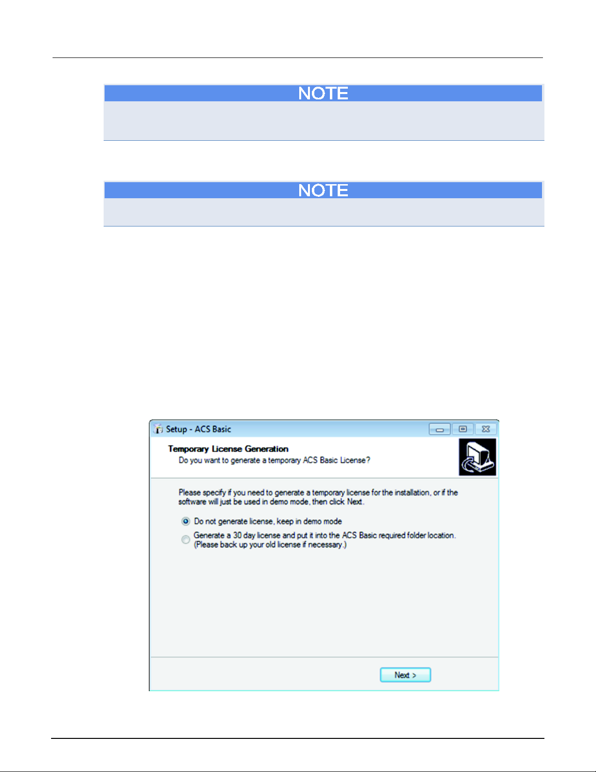
When the installation process is complete, the Temporary License Generation dialog box opens (see
next figure)(note that if you already have a USB license key, select "Do not generate license, keep in
demo mode" in order to continue installation).
Figure 1: Temporary license generation dialog box
2-2 ACSBASIC-901 Rev. E / August 2012
Page 12

ACS Basic
ACS Basic software introduction
Automated Characterization Suite Reference Manual Section 2:
After you have installed ACS Basic software, and before you begin to set up any projects or run any
tests, it is recommended that you review the Release Notes. The Release Notes contain valuable
information about known issues and provide guidance on how to handle issues that you may
encounter. The Release Notes can be found by clicking on your Windows Start icon > All Programs >
ACS Basic > Reference > Release Notes.
ACSBASIC-901 Rev. E / August 2012 2-3
Page 13

Page 14
ACS Basic GUI ....................................................................... 3-13
Section 3
ACS Basic software overview
In this section:
Before starting ACS Basic ........................................................ 3-1
ACS Basic USB license key ..................................................... 3-2
Operating modes ...................................................................... 3-5
Account management .............................................................. 3-8
Before starting ACS Basic
1. Make sure that all of the instruments are connected with a GPIB/LAN cable. If more than one
Series 2600B SourceMeter
®
instrument is used in a group, make sure that the TSP-Link™
connection has been made correctly. For more information on setting up the hardware, refer to
the Hardware Configuration
topic for specific connection and instrument setup instructions.
2. Make sure that all the instruments are turned on and self-testing is completed on all of the
instruments.
3. Assign GPIB addresses and node numbers (see Configure the GPIB interface
information).
for more
Start ACS Basic
1. Click the ACS Basic icon (either a desktop icon or a quick launch icon chosen at installation). You
can also find in the Start menu.
FATAL ERROR POSSIBLE. To avoid fatal errors to instruments, never start ACS Basic software until
all the instruments have completed self-testing. For those who are using Series 2600 and 2600B
instruments with TSP-Link: Always start the "subordinate" instruments first, and then the "master."
Since the master scans through all the linked subordinate instruments, it must be started after all the
subordinate machines are turned on, or errors may occur when you start ACS Basic
You must obtain an ACS Basic software license key in order to start the software in professional
mode. If you have not obtained a USB license key, you can select the Login In Demo Mode function.
This will allow you to start ACS Basic without a software license.
Page 15
Section
Reference Manual
3: ACS Basic software overview ACS Basic Automated Characterization Suite
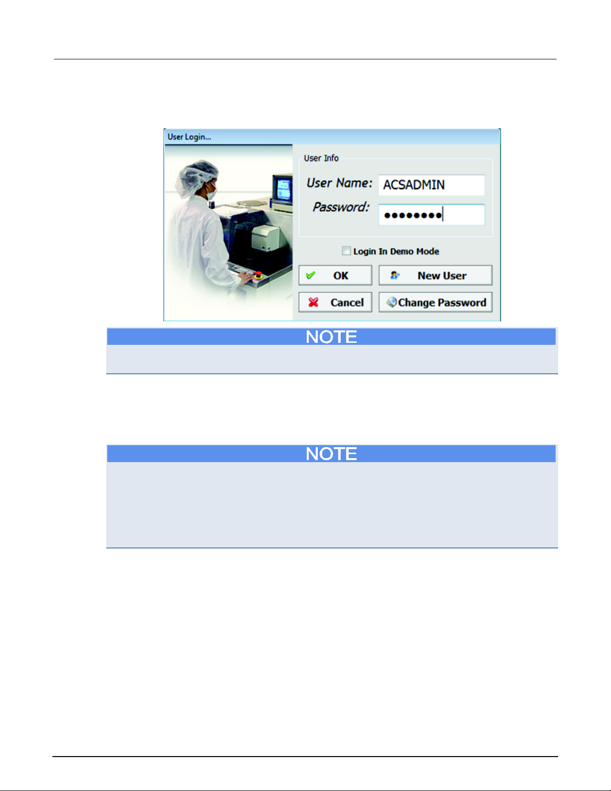
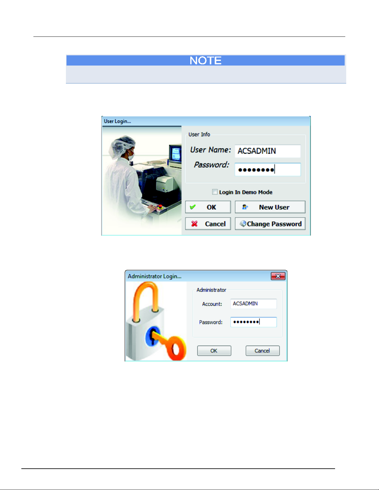
2. Enter the password for ACS Basic in the User Login dialog box (the default User Name is
ACSADMIN, and there is not a default Password; see next figure).
Figure 2: User Login window
As shown in the previous figure, you can register new accounts using the New User function (see
Creating new users). To change your password, use the Change Password function.
ACS Basic USB license key
ACS Basic requires a user license in order to work in either professional or evaluation mode. Upon
installation, the software can generate a temporary license file that is valid for 30 days.
In previous versions of ACS Basic, the licensekey.txt file stored the licensing information. This license
key was tied to the computer ID of a specific computer on which ACS Basic was installed. Once you
have a permanent License File, you can install it by either:
Copying the file into the C:\ACS_BASIC\KATS folder, or while in demo mode, clicking the menu Help
> Update License File and importing the license file. You can also click the Help menu, then Request
a license to learn how to get a license file. The licensekey.txt file will provide you with the ability to
remote login to the system to launch and run ACS Basic.
3-2 ACSBASIC-901 Rev. E / August 2012
Page 16
ACS Basic
ACS Basic software overview
Automated Characterization Suite Reference Manual Section 3:
By default, in the absence of a license key, the software will launch in demo mode. Additionally, if you
do not have any external devices or instruments connected to the computer, a license key will not be
required. However, you will only be able to use ACS Basic in demo mode.
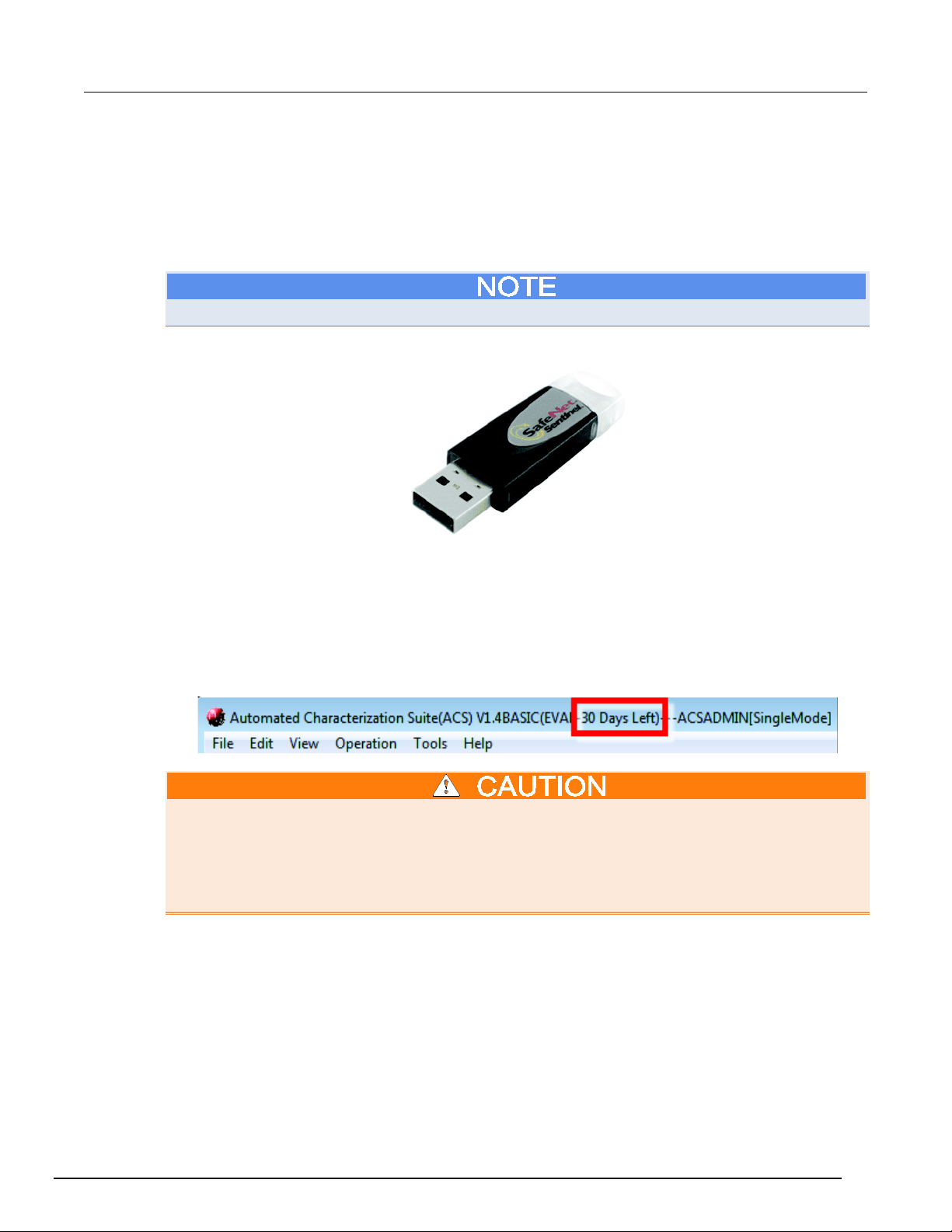
The ACS Basic SafeNet Sentinel USB license key is similar to a standard USB flash drive (see next
figure). The USB license key is included with the ACS Basic software package. The USB license key
allows you to operate ACS Basic in the professional mode or evaluation mode, and can be moved
from one computer to another (multiple installations) without buying additional licenses.
The evaluation license is a temporary key that you can use for 30 days.
Figure 3: USB SafeNet Sentinel license key
Before you start running the ACS Basic software, insert your USB license key into the computer’s
USB interface. The computer and ACS Basic software will automatically detect the USB key, then
ACS Basic will start in the licensed mode (for example, Professional License or Evaluation License).
If you have the temporary key, ACS Basic will start in the evaluation mode, which has the same
functionality as professional mode. The status of the temporary license key and the amount of days
that you have available is displayed while running ACS Basic in the title bar (see next figure).
Figure 4: Evaluation mode with temporary license file
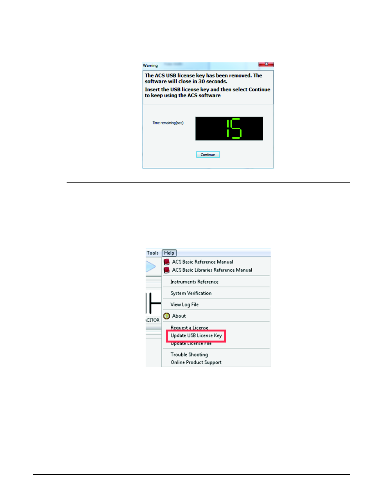
DO NOT remove the USB key from the computer while you are using the ACS Basic software in the
professional or evaluation mode. If the key is removed, you will receive a warning message that
indicates you have 30 seconds to insert the USB key back in the computer (see next figure). After the
key is reinserted in the computer, you must click Continue in order to keep ACS Basic functioning. If
the key is not inserted in the computer before the time has elapsed, the software will close and you
will lose all data from your current session.
ACSBASIC-901 Rev. E / August 2012 3-3
Page 17
Section
Reference Manual
3: ACS Basic software overview ACS Basic Automated Characterization Suite
Figure 5: USB Warning message
Update a temporary USB key
If your temporary USB license key has expired, you can request an update from Keithley Instruments.
To avoid an interruption in your operations and continue using the ACS Basic software in evaluation
mode, perform the following steps to obtain an updated license key file.
Update a USB key:
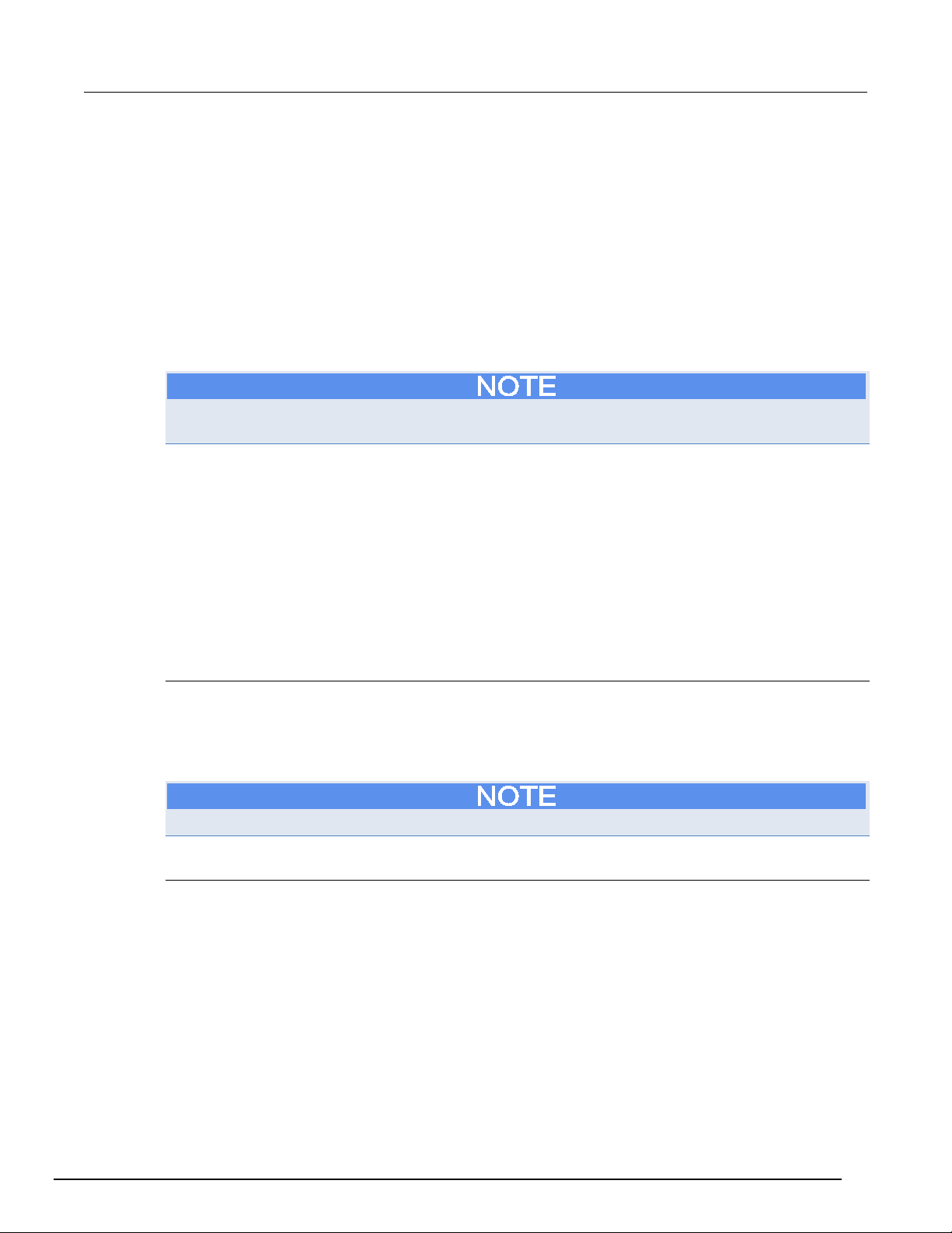
1. In the ACS Basic Help menu, click Update USB License Key (see next figure).
Figure 6: Update License Key
3-4 ACSBASIC-901 Rev. E / August 2012
Page 18
ACS Basic
ACS Basic software overview
Automated Characterization Suite Reference Manual Section 3:
2. After you select Update USB License Key, the Secure Update Utility dialog box opens. Click the
Generate Request Code function to generate a file and save it.
3. E-mail the generated file to the following address: [email protected]
4. After you send the generated file to Keithley Instruments, an updated file will be generated and
returned to you by e-mail.
5. The newly generated file is named ACS_Basic update.upw, or something similar.
6. After you receive the updated file for your USB key, save it to a location on the computer.
7. In the ACS Basic Help menu, click Update USB License Key.
8. In the Secure Update Utility dialog box, click the folder icon to browse and locate the file you
received. Select the file and click Open to upload it.
9. In the Secure Update Utility dialog box, click the Apply Code function.
Before the temporary USB license key expires, you can purchase a permanent license key for ACS
Basic to maintain full functionality.
Operating modes
ACS Basic starts in one of three different operating modes, depending on your license status and
hardware setup (refer to the ACS Basic license key topic for more information). The three possible
modes are:
• Demo
• Evaluation
• Professional
Demo mode
Demo mode is suitable for developing test projects and for reviewing results from previous tests.
When instruments are connected to the computer and ACS Basic starts in demonstration mode, then
the USB license key is not correctly installed or has expired (see the Update a temporary USB key
topic for more information) or has not been purchased.
In Demo mode, ACS Basic cannot communicate with test or measurement hardware.
Evaluation mode
This mode has all of the functionality of ACS professional and lasts for 30 days. It requires a USB
license key that contains a temporary license. See the Update a temporary USB key topic to find out
how to renew your key.
ACSBASIC-901 Rev. E / August 2012 3-5
Page 19
Section
Reference Manual
3: ACS Basic software overview ACS Basic Automated Characterization Suite
Professional mode
When ACS Basic starts in professional mode, it is an indication that the software has a valid USB
license key.
ACS Basic may indicate that the default project requires hardware that is not available when starting
in professional mode. You will notice this indication when ACS Basic is started for the first time with a
new hardware configuration.
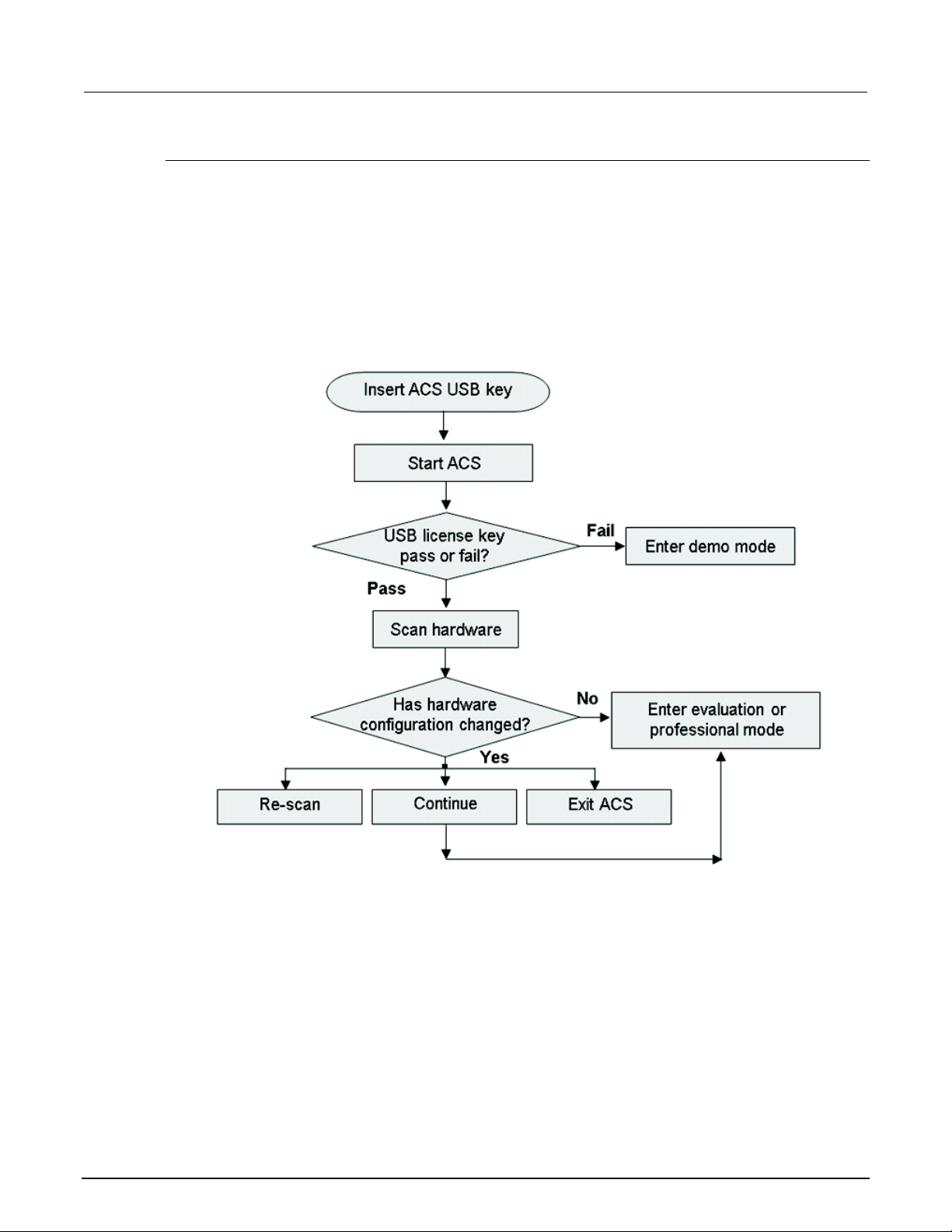
The following flowchart (see next figure) gives an example of the software’s internal process flow
during the startup sequence. The software modes are based on the USB license key and hardware
configuration.
Figure 7: License key software modes
3-6 ACSBASIC-901 Rev. E / August 2012
Page 20
ACS Basic
ACS Basic software overview
Automated Characterization Suite Reference Manual Section 3:
Once the scan has completed, the software determines the state of the configured hardware. If
nothing has changed, ACS Basic will automatically go to professional (online) mode or evaluation
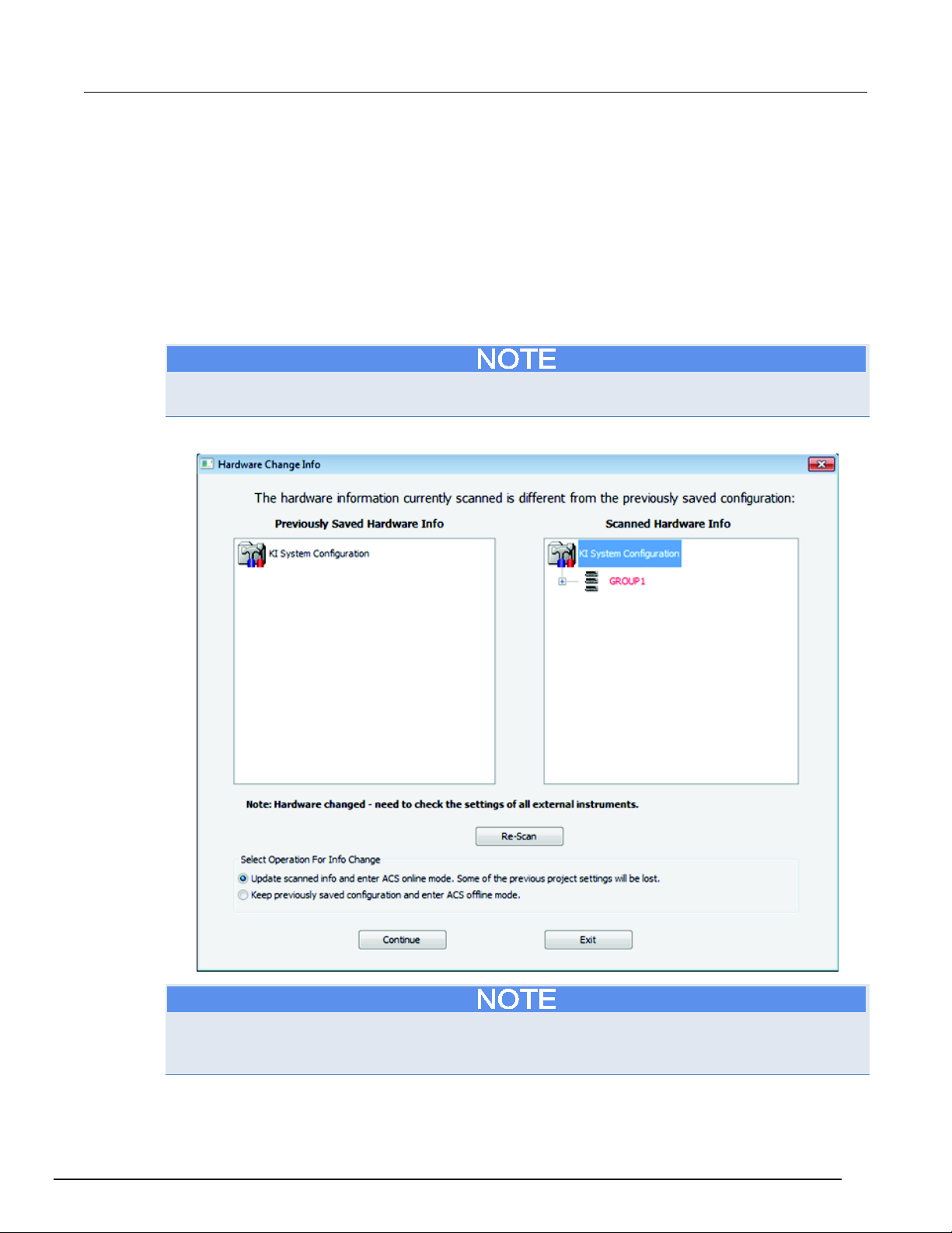
(online) mode depending on your license key. However, if ACS Basic detects a different hardware
configuration, compared to the currently saved configuration (for example, the physical hardware
configuration does not match the configuration on file), a verification dialog box opens. You can select
Re-scan, Continue, or Exit (see next figure).
1. Re-scan: will re-scan all connected instruments.
2. Continue: will accept the newly scanned hardware as the current configuration and continue in
online mode, if the "Keep previously saved configuration and enter ACS online mode" is selected.
3. Exit: will exit ACS Basic without updating the hardware configuration file.
If you have not obtained an ACS Basic software USB license key, then ACS Basic will start in Demo
mode, regardless of any changes to the hardware configuration.
Figure 8: Hardware change info
When the ACS Basic software is started in professional or evaluation mode, the startup time will
depend on how many instruments are in the hardware configuration group. For example, if there are
several instruments, the startup time will be longer.
ACSBASIC-901 Rev. E / August 2012 3-7
Page 21
Section
Reference Manual
3: ACS Basic software overview ACS Basic Automated Characterization Suite
Account management
User accounts
ACS Basic software provides three types of user accounts and each has different rights and security
features.
1. Administrator (or engineer administrator): This account has unrestricted rights to create, edit,
and run test projects, including test parameters within ACS Basic. The administrator can also edit
or delete operator accounts. The default administrator account user name is ACSADMIN (case
sensitive).
There can be other engineer user accounts, however, there is only one engineer administrator.
2. Engineer: This account has unrestricted rights to create, edit, and run test projects, including test
parameters within ACS Basic. However, an engineer account cannot edit or delete operator
accounts.
3. Operator: This account can open and run available test projects that were created by either an
Engineer or Administrator.
Creating new users
Only the administrator account (ACSADMIN) has the necessary rights to add a new Operator or
Engineer account.
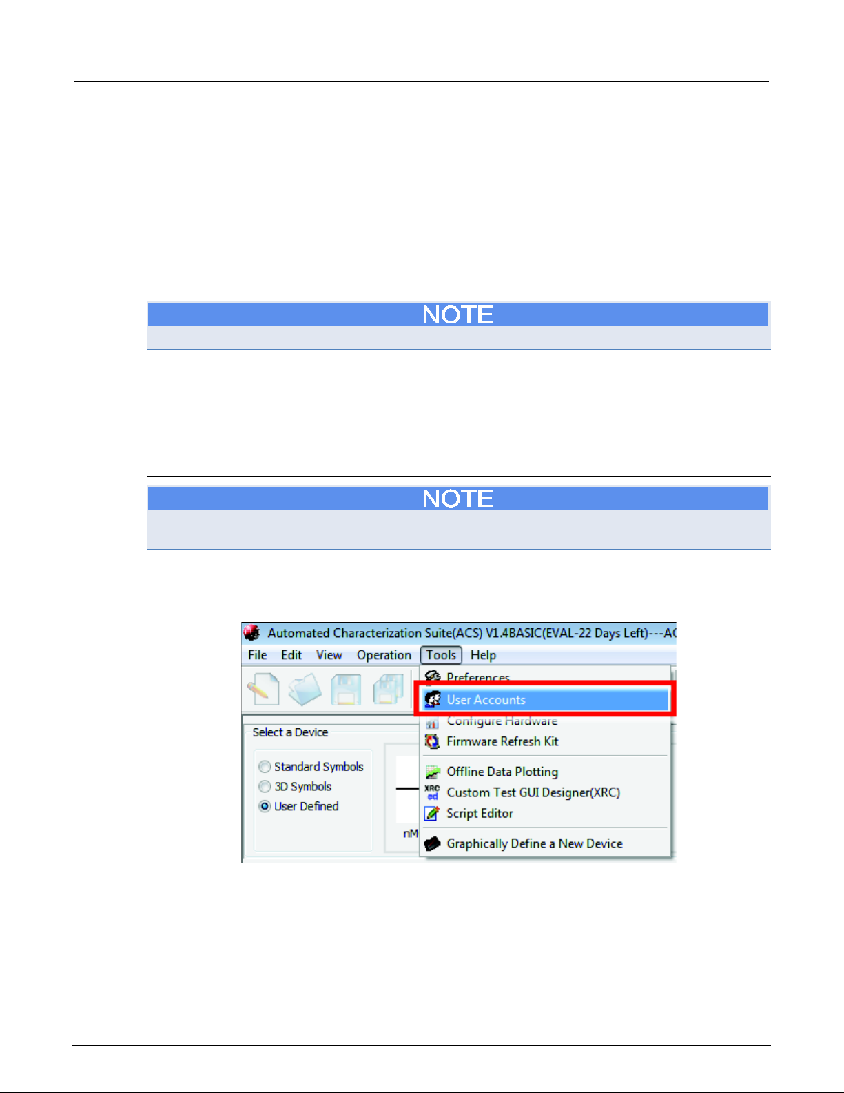
If you are currently logged in to ACS Basic, you can click on Tools and select User Accounts from the
drop-down menu (see next figure).
Figure 9: User Accounts location
3-8 ACSBASIC-901 Rev. E / August 2012
Page 22
ACS Basic
ACS Basic software overview
Automated Characterization Suite Reference Manual Section 3:
Only the administrator account (ACSADMIN) will see the complete list of user accounts. Engineer
accounts will only see their own account. Operators do not have access to this feature.
If you are not logged in to ACS Basic, you can click on the New User function in the User Login GUI
(see next figure).
Figure 10: User Login window
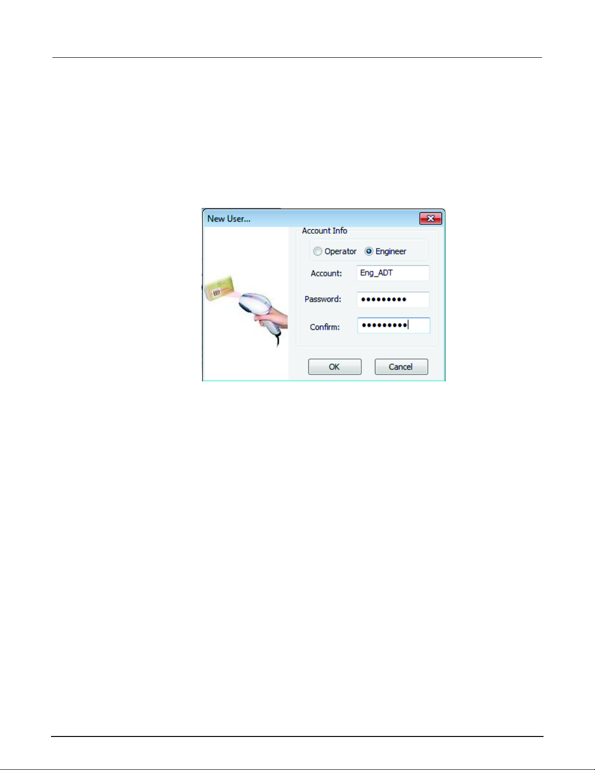
• The Administrator Login dialog box opens (see next figure).
• Enter the password for the Administrator (the default Administrator account name is ACSADMIN).
Figure 11: Administrator login dialog box
ACSBASIC-901 Rev. E / August 2012 3-9
Page 23
Section
Reference Manual
3: ACS Basic software overview ACS Basic Automated Characterization Suite
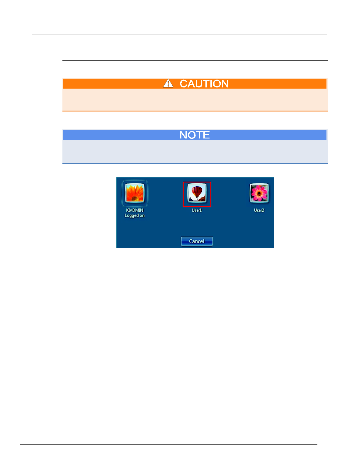
• Click OK, and a New User dialog box opens (see next figure).
• Select the type of account you would like to create: Operator or Engineer
a. An Operator account allows you to load and run test projects.
b. An Engineer account allows you access to all of the ACS Basic functions.
• Enter your Account name and Password.
• Enter your password again in the Confirm field.
• Click OK, and the new user account is complete.
Figure 12: New User dialog box
3-10 ACSBASIC-901 Rev. E / August 2012
Page 24
ACS Ba
ACS Basic software overview
sic Automated Characterization Suite Reference Manual Section 3:
Initialize multiple user accounts
This information is for those who need to initialize multiple user accounts in a Windows® environment.
If you try to run ACS Basic on a computer that has more than one Windows user account and you
have not initialized all of the accounts to run ACS Basic, you will receive an error. Refer to the
following information to establish multiple user accounts in a Windows environment.
This information is for those who have more than one user account when logging in to a Windows
environment (see next figure). If you have more than one user account on your computer, make sure
that you are logged into the user account where ACS Basic was installed.
Figure 13: Windows User Accounts
ACSBASIC-901 Rev. E / August 2012 3-11
Page 25
Section
l
3: ACS Basic software overview ACS Basic Automated Characterization Suite Reference Manua
If the administrator (for example, Admin1) has already installed ACS Basic software, none of the
other users (User1 or User2) need to install the software. However, you do need to initialize the user
accounts (User1 and User2) so that they have access to ACS Basic software.
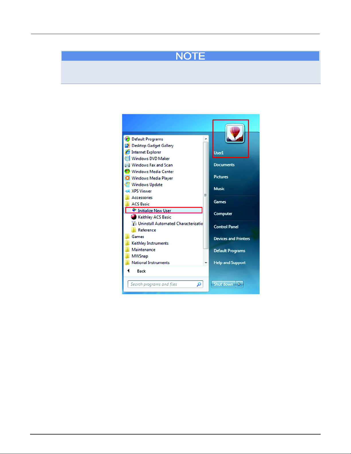
After logging in to a user account (for example, User1), click on your Windows Start function and find
ACS Basic in All Programs. Click the Initialize User function (see next figure).
Figure 14: Windows Start Function
After you click the Initialize User function, you must restart your computer.
Once your computer reboots, you can log in to Windows with your initialized account and run ACS
Basic software.
3-12 ACSBASIC-901 Rev. E / August 2012
Page 26

ACS Basic
ACS Basic software overview
Automated Characterization Suite Reference Manual Section 3:
Change password
Only the administrator account (ACSADMIN) has the necessary rights to change a password for all of
the user accounts. An engineer account can change its own password, but not any other accounts.
An operator does not have access to this function.
While in the User Accounts window, select the account that will have the password changed.
Click the Edit button to open the Change password dialog box. Enter the current password of the
account, enter a new password, and then confirm in the appropriate fields.
Delete user account
Click OK to complete the process.
Only the administrator account (ACSADMIN) has the necessary rights to delete user accounts. The
engineer and operator account do not have access to this function.
While in the User Accounts window, select the account you want to delete and click the Delete
button. To complete the process click Yes when asked if you want to delete the account.
ACS Basic GUI
When you first open ACS Basic, the default test mode that you will see is Single-test mode. ACS
Basic has three test modes available:
1. Single-test mode
2. Multi-test mode
3. Trace mode
Operation toolbar
The Operation toolbar is located at the top of the ACS Basic GUI and contains a set of functions that
allow you to perform the following tasks (see next figure), New project, Open project, Save project,
Save All, Run, Repeat, Append, Pause, Stop, Clear Append, Hardware Configuration, Scan
Hardware, and choose a Mode option (this list of tasks corresponds with the icons in the Operation
toolbar from left to right).
ACSBASIC-901 Rev. E / August 2012 3-13
Page 27
Section
Reference Manual
3: ACS Basic software overview ACS Basic Automated Characterization Suite
Project file management icons
New, Open, Save, and Save All icons (used in Multi-test mode)(See the following test mode topics
for more information: Single-test mode (on page 5-4), Multi-test mode (on page 5-10), Trace mode
(on page 5-15).
These functions allow you to create and manage project files in Multi-test mode:
• New: creates a new project
• Open: opens an existing project
• Save: saves all project settings of the configuration navigator
• Save All: saves all project settings and test result data
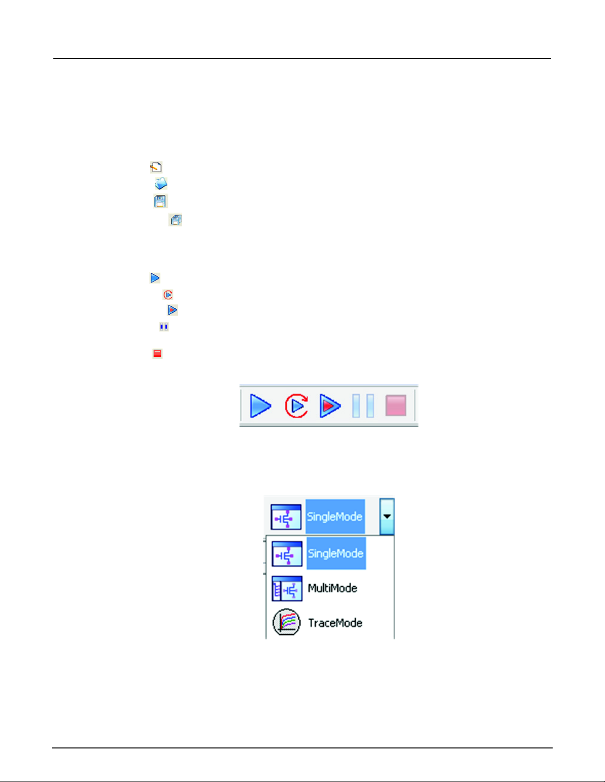
Test control icons
Run, Repeat, Append, Pause, and Stop icons (see next figure).
• Run: initiates the test procedure
• Repeat: continues test execution until Stop is selected
• Append: initiates a test procedure and appends data in a new Data tab
• Pause: allows you to temporarily stop the test flow (the test will pause right after the current
operation is completed; the next test will not execute in multi-test mode.)
• Stop: immediately ends the test
Figure 15: Run, Repeat, Append, Pause, and Stop functions
Multi-mode, Single-mode, and Trace mode
These functions are used to switch between different test modes. You have to click the down-arrow to
access the test modes (see next figure).
Figure 16: Multiple-mode, Single-mode, and Trace-mode
3-14 ACSBASIC-901 Rev. E / August 2012
Page 28
ACS Basic
Basic software overview
Automated Characterization Suite Reference Manual Section 3: ACS
• Single-mode: allows you to perform a single test on a single device.
• Multi-mode: allows you to perform multiple tests on a single device (target application), or
multiple tests on multiple devices. It is easier to use external instruments (DMM, switch, etc.) in
multi-mode.
• Trace mode: allows you to perform interactive operations with a SourceMeter. You can adjust the
maximum sweep value and maximum power into the device. You can also easily transition
between DC and pulse forcing modes.
If you switch between the Single-test mode and the Multi-test mode, your test settings and data may
be lost. Therefore, it is recommended that you save your test data before you switch modes.
Single-test mode icons
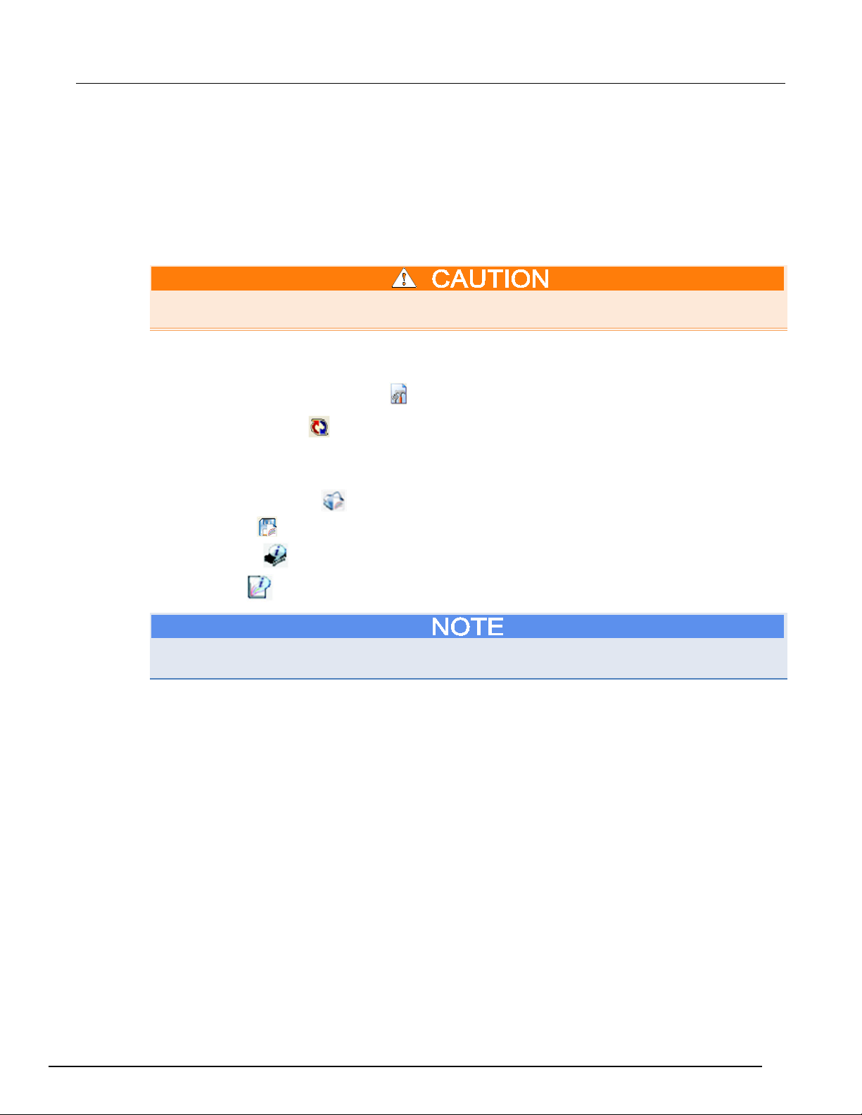
Click the Hardware configuration icon
The Scan hardware icon
is enabled when the hardware configuration GUI is open. This function
to access the configure hardware utility GUI.
scans the hardware and updates the test hardware information
The following functions are active only in the Single-test mode:
• Return to Library view: opens a test module in the device library.
• Export Test: saves a test module to the device library.
• Device View: opens a GUI that contains the device setup and connection information.
• Test View: opens a GUI that contains the test configuration information.
The Device view and Test view functions do not appear simultaneously. For example, when in Device
view, the Test view function opens; when in Test View the Device View function opens.
ACSBASIC-901 Rev. E / August 2012 3-15
Page 29
Section
Reference Manual
3: ACS Basic software overview ACS Basic Automated Characterization Suite
ACS Basic GUI icons
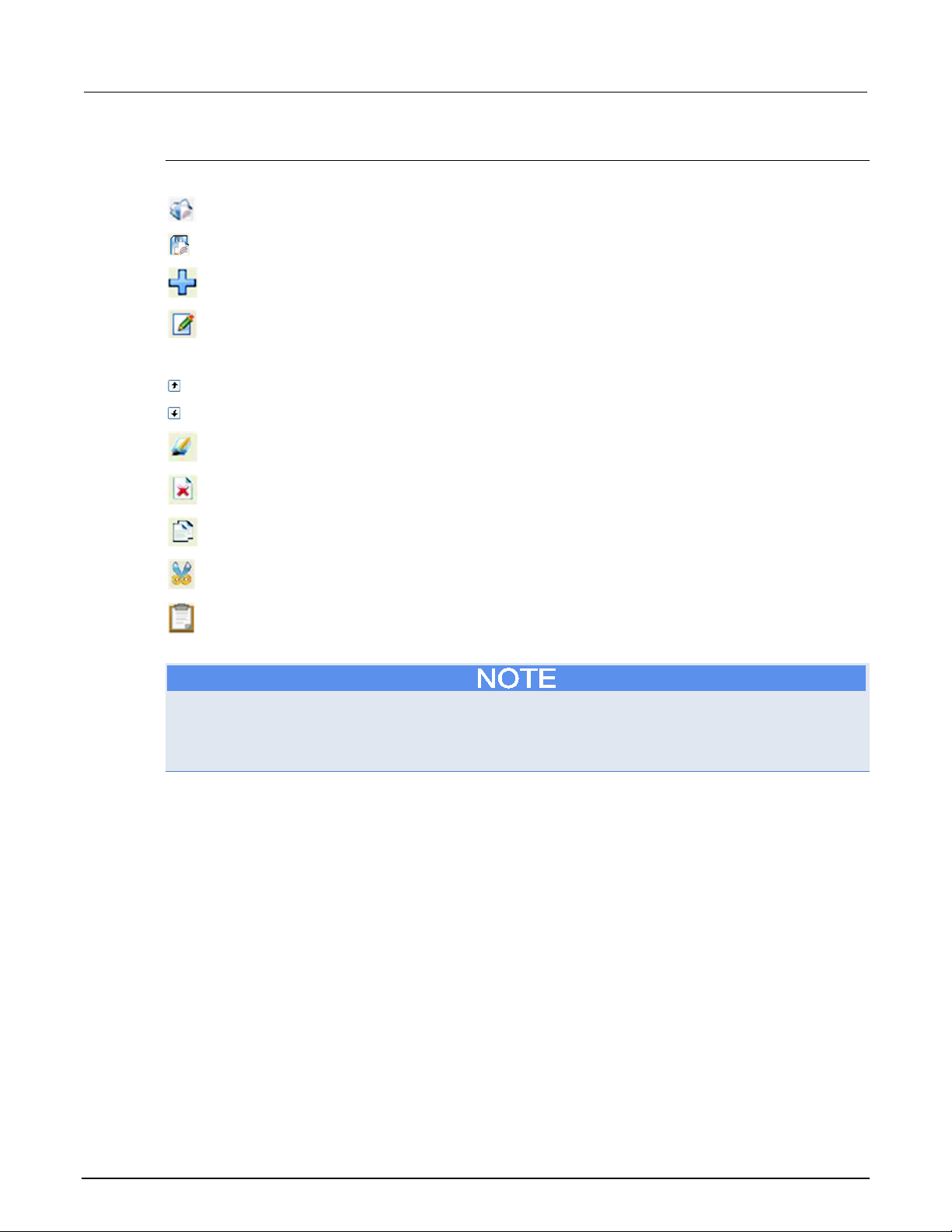
Test setup icons
Return to Library View returns to the GUI to add a test module from the library.
Export Test exports the current test module to the library.
Add new Device/Test Module allows you to add a device or an ITM, STM, or PTM test module.
Launch Script Editor allows you to access the editing tool to edit the library.
Project management icons
Move Test Module Up moves the selected test to the next spot in the Configuration Navigator.
Move Test Module Down moves the selected test to the next spot in the Configuration Navigator.
Rename allows you to rename a pattern, subsite, device, or test module.
Delete allows you to delete a selected pattern, subsite, device, or test module.
Copy allows you to make a copy of a pattern, subsite, device, or test module.
Cut allows you to cut a pattern, subsite, device, or test module.
Paste allows you to paste a pattern, subsite, device, or test module in the Configuration
Navigator. It only appears after Copy or Cut has been selected.
If you copy a test module (for example, an ITM), and past it under another device where the attributes
and settings do not match the original device, you will lose the test module's information. Please
ensure that you are copying and pasting between devices that contain the same attributes and
settings.
3-16 ACSBASIC-901 Rev. E / August 2012
Page 30
ACS Basic
ACS Basic software overview
Automated Characterization Suite Reference Manual Section 3:
Log message window
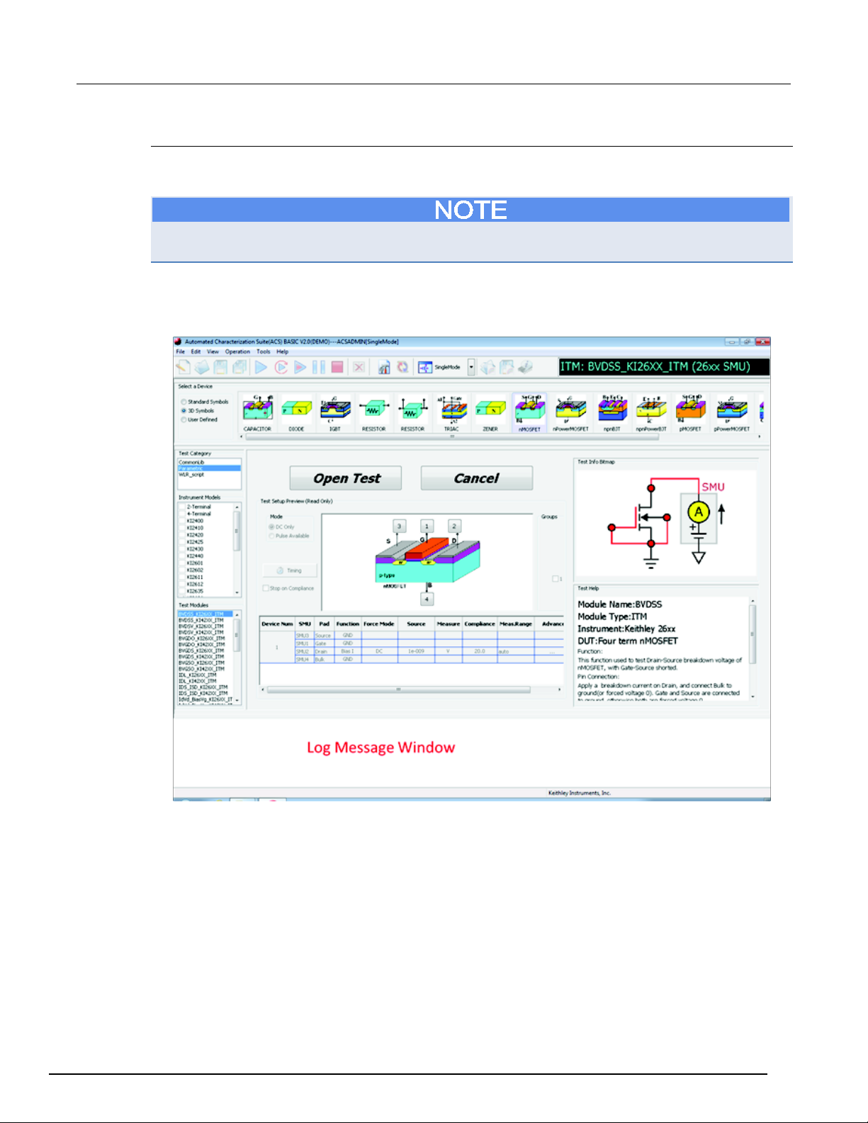
When you run a python test module (PTM) or script test module (STM), ACS Basic will log the
commands, errors, warning messages, and some test results in the log message window.
The log window is not used for interactive test modules (ITMs). That is, the ITM test will not display in
the log message window (see next figure).
The log message window is located at the bottom of the ACS Basic GUI (see next figure). The log
message displays in the log window in real time.
Figure 17: Log message window
ACSBASIC-901 Rev. E / August 2012 3-17
Page 31
Section
Reference Manual
3: ACS Basic software overview ACS Basic Automated Characterization Suite
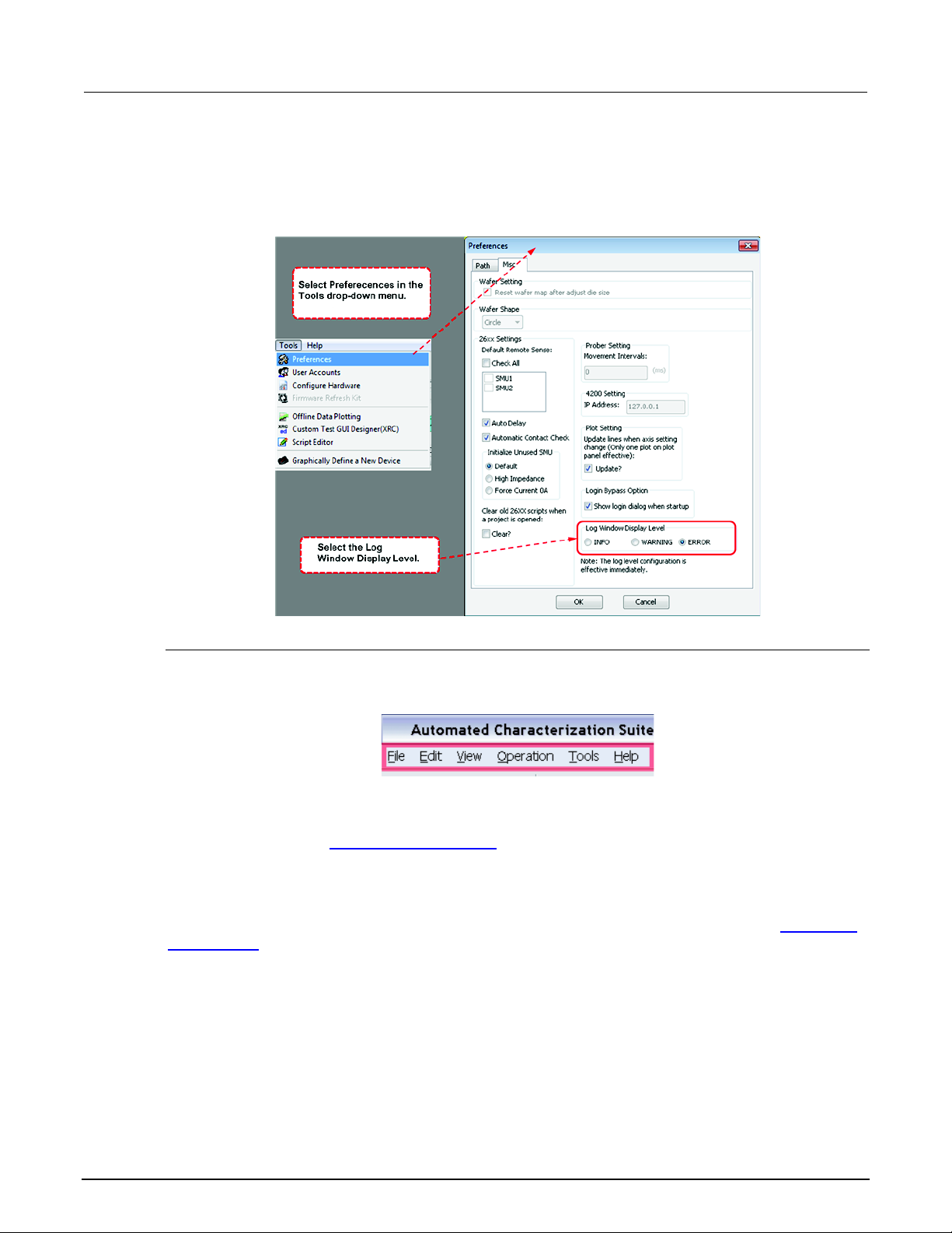
In the View menu, you can choose to show or hide the log window. By default, it is hidden.
You can also select the log level to display in the log message window: Info, Warning, or Error in
Tools > Preferences settings (see next figure).
Figure 18: Preference setting for Log Level
Menu toolbar elements
The menu toolbar is located at the top of the ACS Basic GUI (see next figure).
Figure 19: Menu toolbar location
File menu
The New, Open, Save, Save as Template, and Save All functions are the same as previously
described. Refer to the Project file management
functions topic. These functions are only enabled in
multi-mode. Only the EXIT button can be used in single-mode.
Edit menu
The Copy, Cut, and Delete functions are the same as previously described. Refer to the
management functions topic for more information. Also, the Edit menu is disabled in Single-mode.
View menu
Only the Show Log Window item can be accessed in ACS Basic
Project file
3-18 ACSBASIC-901 Rev. E / August 2012
Page 32
ACS Basic
ACS Basic software overview
Automated Characterization Suite Reference Manual Section 3:
Operation menu
The Run, Repeat, Append, Pause, Stop, and Clear Append functions are the same as previously
described. Refer to the Test control
functions topic, if you need more information. Notice that Repeat,
Pause, and Stop are disabled when you are in single-mode.
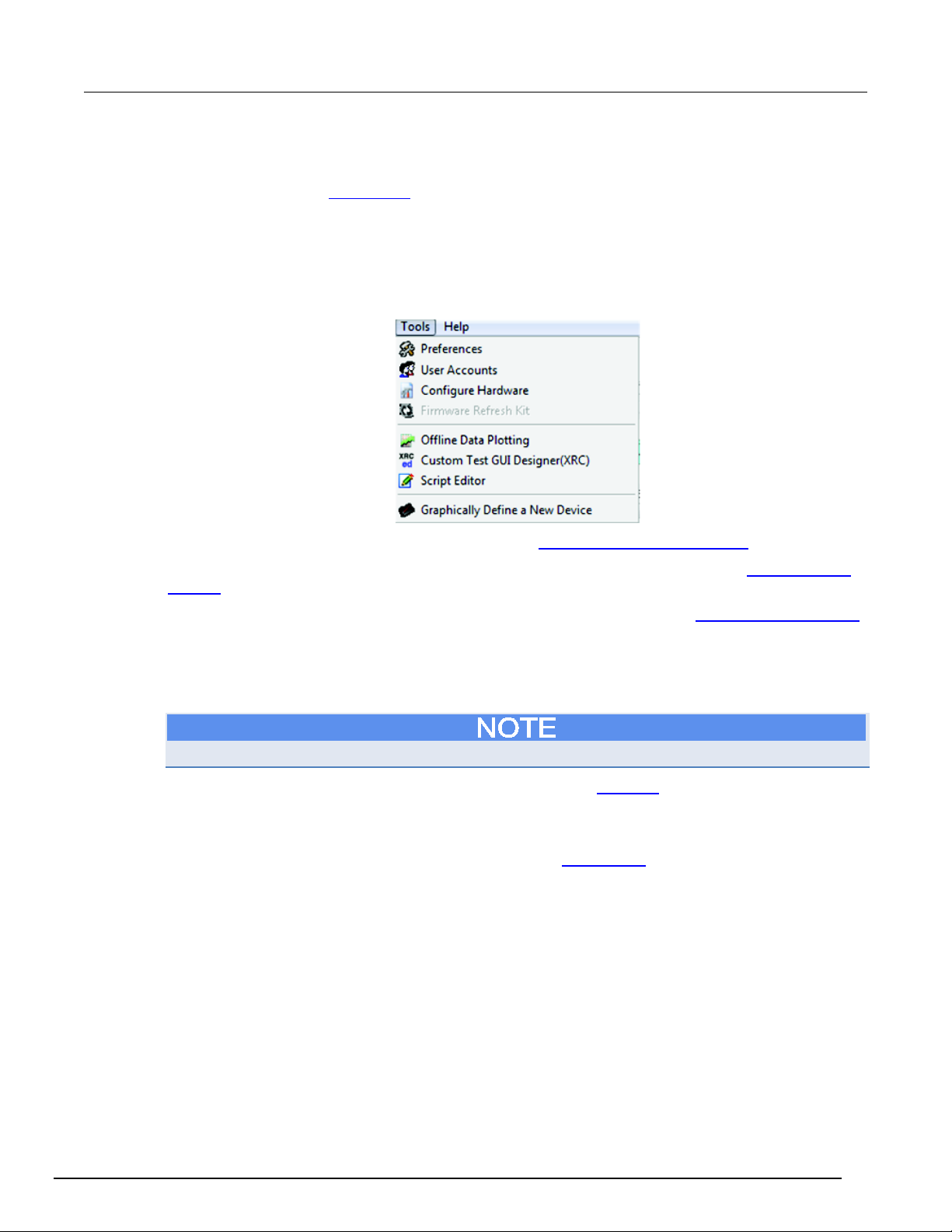
Tools menu
There are several functions available in the Tools menu (see next figure).
Figure 20: Tools menu
Preferences: set advanced preferences. Refer to the Advanced Setting Preferences for details.
User Accounts: view the User Admin dialog box for user accounts information (see User accounts
security for details).
Configure Hardware: access the hardware configuration utility. Refer to the Hardware Configuration
topic for details.
Firmware Refresh Kit: refresh the Series 2600 or Series 2600B firmware. This utility verifies or
performs updates on the firmware on any Series 2600 and 2600B instruments connected to the ACS
Basic. Any updates will be made using firmware files stored locally on your computer or network.
The latest firmware files are available for download on www.keithley.com.
Offline Data Plotting: access the Data Plot Tool. Refer to the Data plot section for details.
Custom Test GUI Designer (XRC): access the GUI builder. Refer to Create a TSP GUI file for
details.
Script Editor: access the Script Editor Tool. Refer to the Script Editor
tool for details.
Graphically Define a New Device: access the device editor tool. For more information on the Device
Editor refer to the Graphically define a new device for details.
ACSBASIC-901 Rev. E / August 2012 3-19
Page 33
Section
Reference Manual
3: ACS Basic software overview ACS Basic Automated Characterization Suite
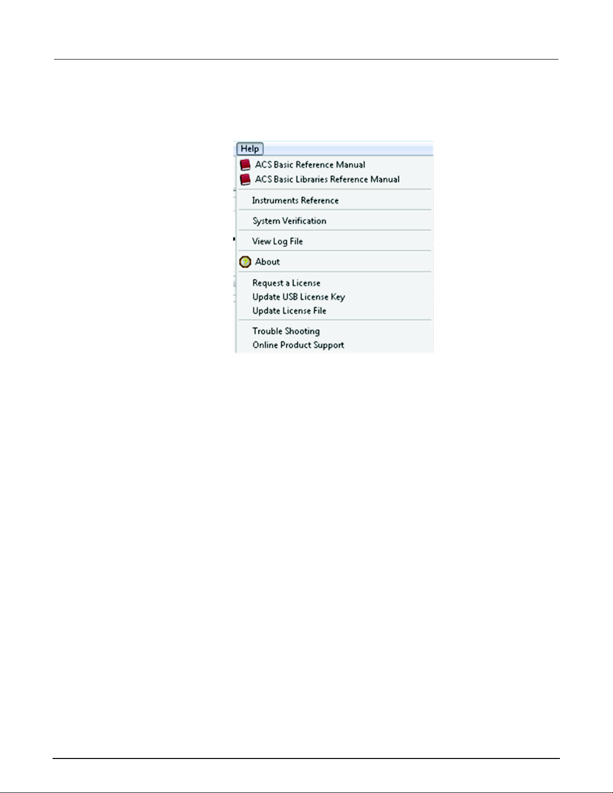
Help menu
You have many items available in the Help menu for ACS Basic (see next figure).
Figure 21: Help menu
3-20 ACSBASIC-901 Rev. E / August 2012
Page 34

ACS Basic
ACS Basic software overview
Automated Characterization Suite Reference Manual Section 3:
ACS Basic Reference Manual: provides detailed comprehensive information about the software
features
ACS Basic Libraries Reference Manual: contains LPT library programming commands and device
library commands
Instrument Reference: click to find a list of manuals that you can use with ACS Basic supported
instruments, including Series 2400, 2600B, 3700A, Model 4200-SCS, and Models 707A/707B and
708A/708B .
All of the products that Keithley Instruments manufactures are located on our website. You can
search for a specific product and find updated manuals anytime by clicking this link:
www.keithley.com.
System Verification: click to open the verification project in multiple-test mode.
View Log File: click to open the saved log file.
About: click to learn more About ACS Basic, such as the build date and type, plus other general
information.
Request a License: click to receive a dialog box that gives detailed information on how to request a
license.
Update USB License Key: click to open the update license Key dialog. Refer to the Update a
temporary USB key for instructions.
Update License File: if you request a license file, you will receive instructions on how to update your
new license file; additionally, when you click this option, it will take you to the area where your license
key is located.
Trouble Shooting: shows system information, such as hardware and software information, including
information about your computer and your version of ACS Basic. You can save this information if you
need to request a license, or send it to a Keithley Instruments applications engineer for
troubleshooting.
Online Product support: click to open Keithley Instruments’ online product support website:
www.keithley.com/support
. Here you will be able to find all the information that you want on Keithley’s
products.
ACSBASIC-901 Rev. E / August 2012 3-21
Page 35

Configure the hardware in demo mode .................................. 4-38
Section 4
ACS Basic hardware configuration
In this section:
Introduction .............................................................................. 4-1
Configure hardware function .................................................... 4-2
Supported communication interfaces ....................................... 4-3
Connect to a single instrument ................................................. 4-3
Connect to multiple instruments ............................................... 4-9
Connect to Model 4200-SCS SMUs ....................................... 4-14
Connect to external instruments ............................................. 4-18
View and setup instrument properties .................................... 4-22
Save the hardware configuration ............................................ 4-37
Check the hardware configuration .......................................... 4-37
Introduction
The Automated Characterization Suite (ACS) Basic hardware configuration utility is used to manage
the hardware configuration of the following Keithley instruments:
• Series 2400 SourceMeter
• Series 2600 SourceMeter Instruments
• Series 2600B SourceMeter Instruments
• Model 707A/707B and 708A/708B Switching Matrices
• Series 2400 SourceMeter Instruments
• Series 3700A System Switch/Multimeter
• External GPIB instruments and all external system components supported by the ACS Basic
software tools (refer to Connect to external instruments
Using the hardware configuration utility, these instruments can be easily added, configured, and
removed from the system configuration.
If you make changes to the hardware (for example, remove one instrument, change the 707B work
mode, change node information, etc.) while ACS Basic is running, you must also do the following
tasks:
1. Click the Scan Hardware function in the toolbar to re-scan hardware.
2. Click the Save function to update the changes.
3. Close and restart ACS Basic for the changes to take effect.
4. Check the test setup to ensure the new hardware configuration is correct.
If the above tasks are not completed, the results from your tests may not be accurate.
®
Instruments
topic for more details).
Page 36
Section
Reference Manual
4: ACS Basic hardware configuration ACS Basic Automated Characterization Suite
Configure hardware function
The Configure Hardware function is used to get information while scanning the hardware instruments.
To start a scan, click the Configure Hardware option from the Tools menu or click the configure
hardware icon
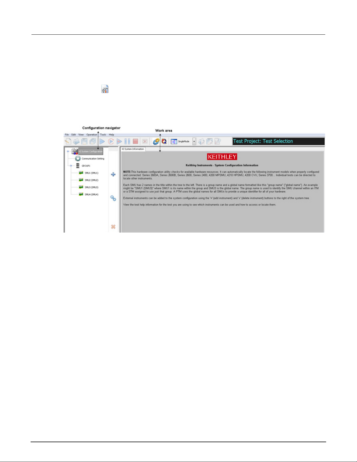
The interface of the hardware configuration utility has two parts: the left panel is the configuration
navigator; the right panel is the work area (see next figure).
on the toolbar.
Figure 22: Hardware configuration interface
The configuration navigator provides a tree view of all the instruments and equipment present in the
ACS Basic hardware configuration. The tree branches can be expanded and minimized by clicking on
the arrows to the left of each branch.
The work area shows each instrument in the system configuration and its associated properties. Click
an instrument in the configuration navigator and the associated properties display in the work area.
4-2 ACSBASIC-901 Rev. E / August 2012
Page 37
ACS Basic
ACS Basic hardware configuration
2400
Desktop/laptop computer
GPIB
2600B
Desktop/laptop computer or 4200
GPIB, Ethernet, TSP subordinate
4200
4200 only
Internal
3700A
Desktop/laptop computer or 4200
GPIB, Ethernet, TSP subordinate
Other external instruments
Desktop/laptop computer or 4200
GPIB
Automated Characterization Suite Reference Manual Section 4:
Supported communication interfaces
ACS Basic software supports the following communication interfaces:
• GPIB (general purpose interface bus)
• Ethernet (also referred to as a LAN)
ACS Basic can also control multiple TSP instruments as a group connected to a single GPIB or
Ethernet interface. Each group uses TSP-Link
Connect to multiple instruments
topic for more information.
™
to connect instruments together. Refer to the
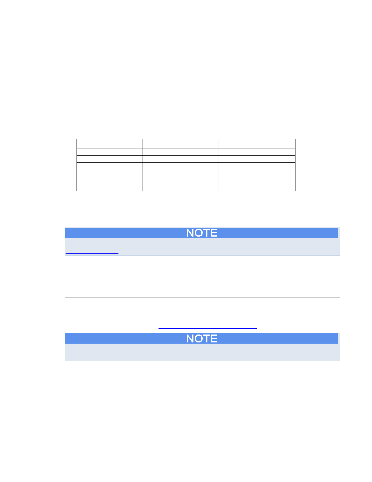
The following table indicates how instruments communicate with ACS Basic (see next table).
Instrument Platform Communication interface
2600 Desktop/laptop computer or 4200 GPIB, TSP subordinate
Connect to a single instrument
Information about connecting to the Model 4200-SCS is not in this section. Refer to the topic Connect
to Model 4200-SCS for more information
When using ACS Basic to control hardware, you must select and configure a communications
interface. If the hardware is configured with a communications interface, when ACS Basic starts it will
automatically scan and find the hardware.
Select an interface
Make sure you choose an interface that is consistent with your instrument’s connection: GPIB or
Ethernet. Some instruments allow multiple communication interfaces to be enabled, however you can
only communicate with one interface at a time using ACS Basic. For more information about
communication interfaces, refer to Supported communication interfaces
See the instrument’s manual for more information on the GPIB and Ethernet communications
interfaces.
ACSBASIC-901 Rev. E / August 2012 4-3
.
Page 38

Section
Reference Manual
4: ACS Basic hardware configuration ACS Basic Automated Characterization Suite
Configure the interface
GPIB interface
ACS Basic automatically scans the GPIB instruments during start.
Supported interfaces
ACS Basic software supports these GPIB interfaces:
• KUSB-488
• KUSB-488A
• KUSB-488B
• KPCI-488
• KPCI-488A
• KPCI-488LP
• KPCI-488LPA
• NI USB-488
• NI PCI-488
GPIB card installation
It is recommended that you install the GPIB card and its associated driver prior to installing ACS
Basic.
For more information on the installation of a GPIB card driver, refer to the GPIB manufacturer’s
interface documentation for installation instructions.
GPIB Driver Compatibility
General
Almost all GPIB interface drivers can be installed before or after ACS Basic has been installed. The
order of installation will not affect the functionality of the software. NI and CEC GPIB interface drivers
are exceptions to this rule, see below.
Keithley Instruments
Uninstalling or reinstalling KITE or Keithley GPIB interface drivers (on a system that has ACS Basic
already installed) may cause ACS Basic to function incorrectly due to .dll errors. To resolve this issue
please reinstall ACS Basic every time KITE or Keithley GPIB interface drivers are uninstalled or
reinstalled.
National Instruments
Uninstalling or reinstalling NI GPIB interface drivers or NI VISA drivers (on a system that has ACS
Basic already installed) may cause ACS Basic to function incorrectly due to .dll errors. To resolve this
issue please reinstall ACS Basic every time NI GPIB interface drivers or NI VISA drivers are
uninstalled or reinstalled.
CEC
ACS Basic supports CEC488 GPIB drivers 8.2 or above. Please upgrade older drivers to ensure
compatibility. Uninstalling or reinstalling CEC GPIB interface drivers (on a system that has ACS Basic
already installed) may cause ACS Basic to function incorrectly due to .dll errors. To resolve this issue
please reinstall ACS Basic every time CEC GPIB interface drivers are uninstalled or reinstalled.
4-4 ACSBASIC-901 Rev. E / August 2012
Page 39
ACS Basic
ACS Basic hardware configuration
Automated Characterization Suite Reference Manual Section 4:
Check the GPIB communication
Prior to starting ACS Basic, it is recommended that you verify that the GPIB card and driver are
installed correctly and are properly functioning in your operating system. For the Keithley/CEC GPIB
interfaces, you can use the following diagnostic utilities: "KI-488 Configuration Utility" and the "KI488 Diagnostic Tool."
For more information on verification instructions on the GPIB communication interface card, refer to
the GPIB manufacturer’s documentation.
Connect instruments with GPIB
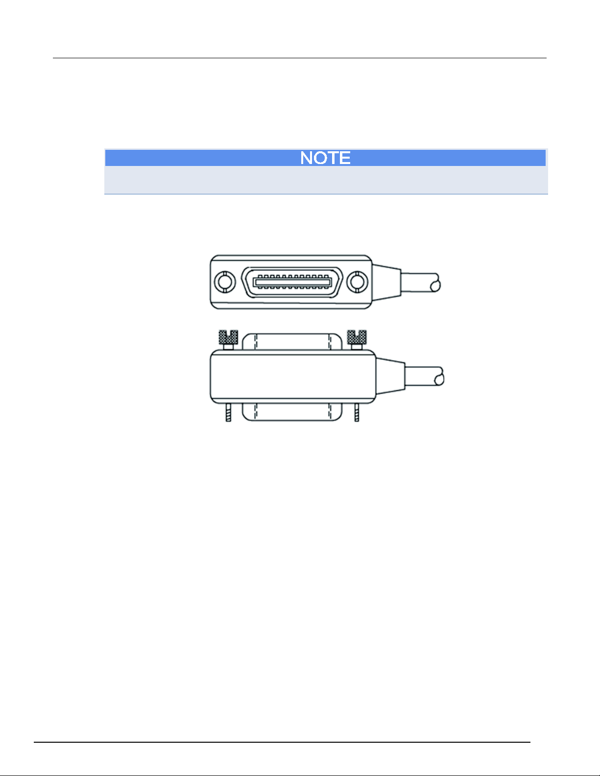
To connect the instruments to the GPIB bus, use an IEEE-488 GPIB cable (see next figure).
Figure 23: Standard IEEE-488 connectors
ACSBASIC-901 Rev. E / August 2012 4-5
Page 40
Section
Reference Manual
4: ACS Basic hardware configuration ACS Basic Automated Characterization Suite
Establish the instrument’s GPIB address and make sure that the instruments are configured for a
GPIB connection and has a valid, unique address. For example, the Series 2600B ships from the
factory with a GPIB primary address of 26. If the GPIB interface is enabled, it momentarily displays
the primary address on power-up. You can set the address to a value from 0 to 30, but do not assign
the same address to another instrument or to a controller that is on the same GPIB bus.
Controller GPIB addresses are usually 0 or 21.
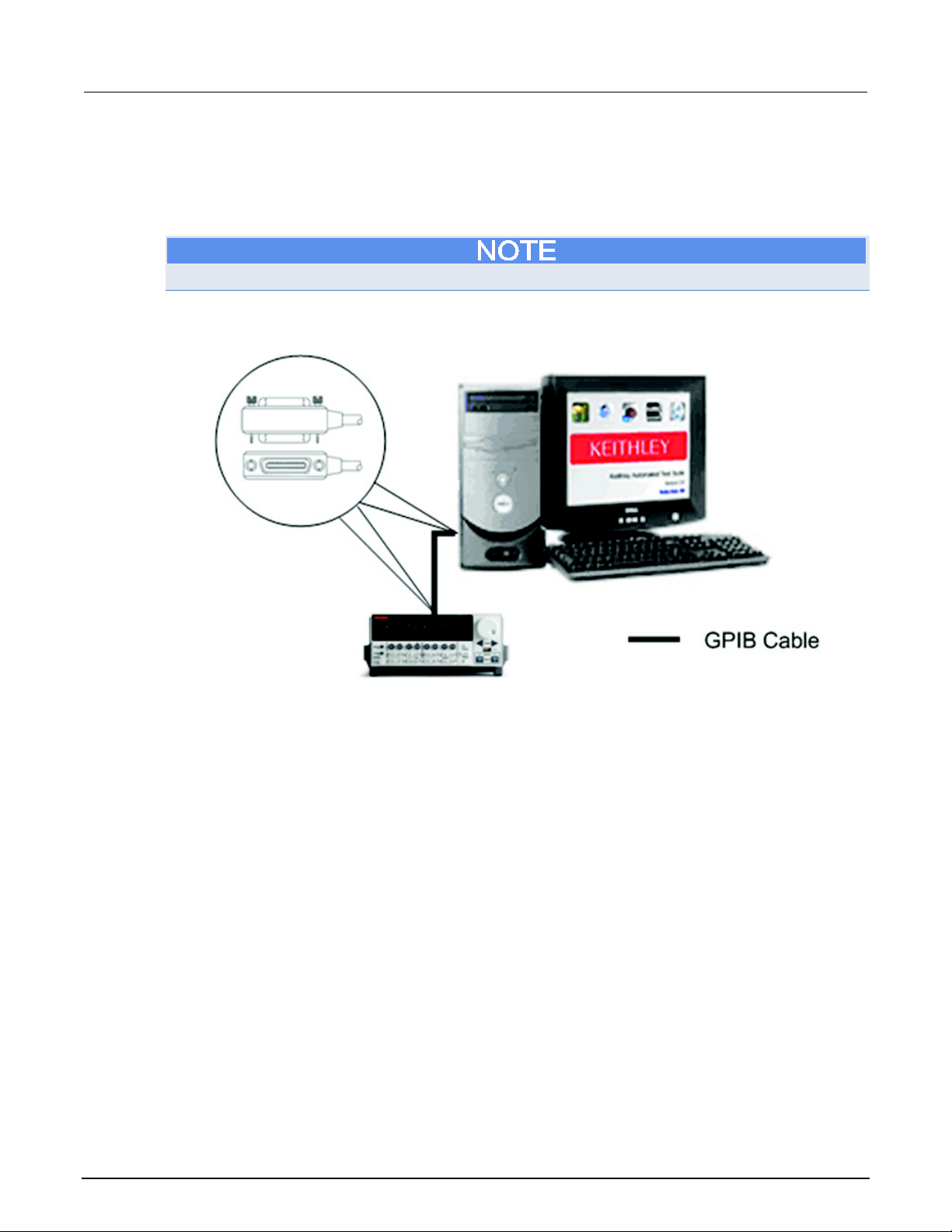
The next figure shows a single instrument connected to a computer over GPIB.
Figure 24: Single instrument GPIB configuration
4-6 ACSBASIC-901 Rev. E / August 2012
Page 41
ACS Basic
ACS Basic hardware configuration
Automated Characterization Suite Reference Manual Section 4:
Ethernet interface
ACS Basic must be manually configured to scan for instruments that are connected to an Ethernet
cable.
Ethernet cable connection
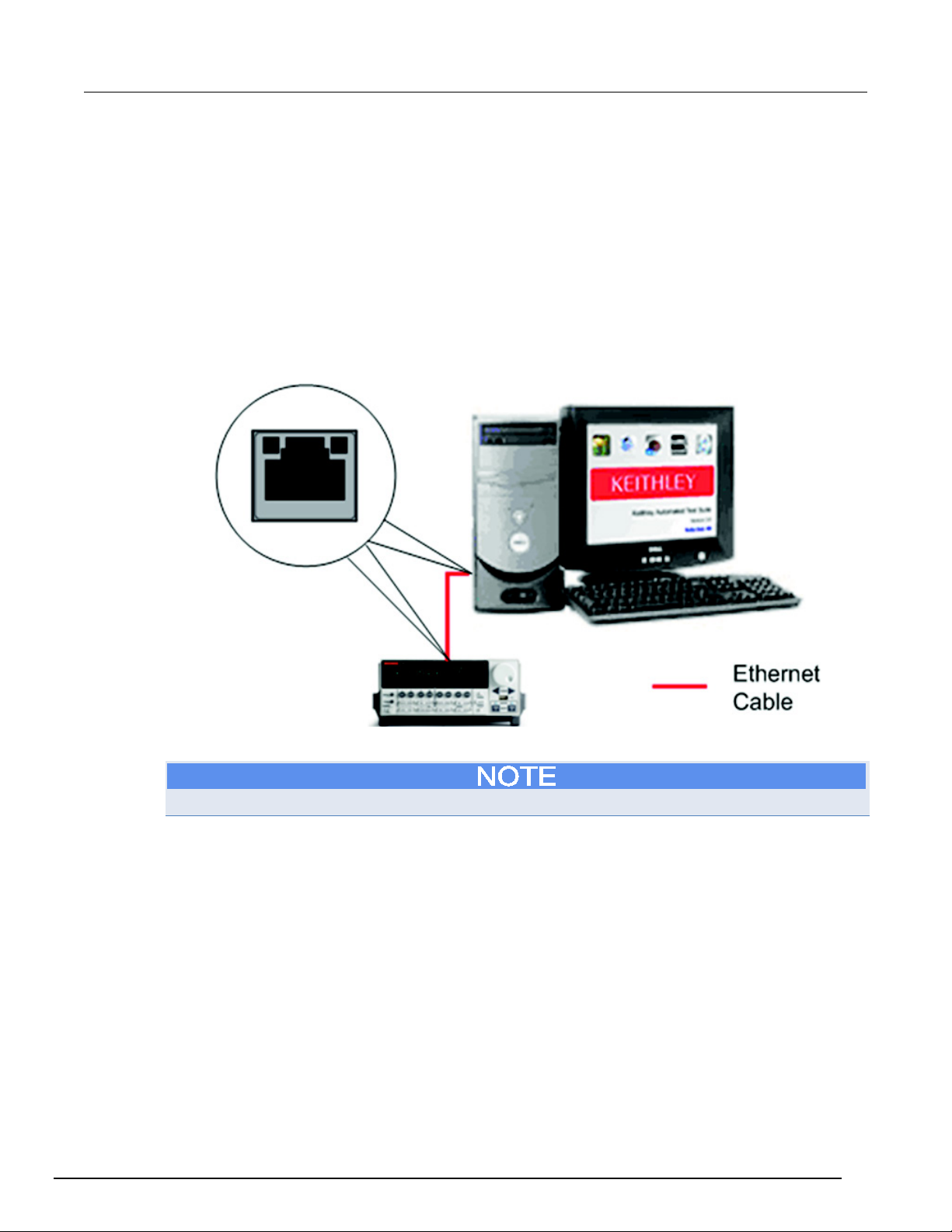
The Series 2600B instruments include two cables (part number: CA-180-3A). Use one cable for TSPLink and use the other cable for the Ethernet connection (for a direct instrument to computer
connection).
• Insert the Ethernet cable into the Ethernet port located on the back of the instrument.
• Insert the cable into the Ethernet port located on the back of the host computer.
Figure 25: Ethernet connection
• Assign an IP address to the instrument.
For more information on how to configure an Ethernet connection, refer to the instrument’s manual.
ACSBASIC-901 Rev. E / August 2012 4-7
Page 42
Section
Reference Manual
4: ACS Basic hardware configuration ACS Basic Automated Characterization Suite
Manually configure Ethernet hardware
To manually configure ACS Basic to scan for Ethernet instruments, first start ACS Basic and change
the settings within the hardware configuration utility.
1. Open the hardware configuration utility
2. Click the Configure Hardware option in the drop-down list in the Tools menu or click the configure
hardware icon
on the toolbar.
Each instrument that uses an Ethernet connection (corporate or private) requires a unique IP
address. In the hardware configuration interface, you can add the IP address of these instruments.
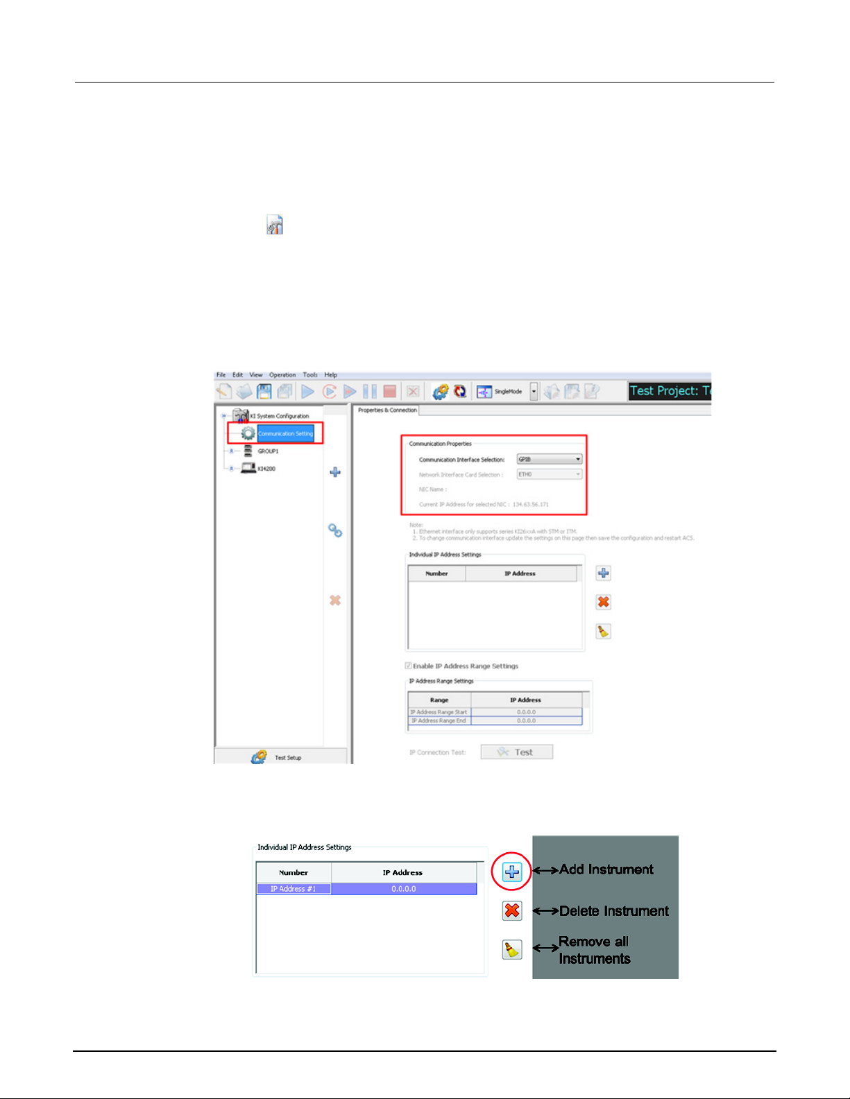
1. Click on the Communication Setting to display the Properties and Connection GUI (see next
figure).
2. Set the communication interface selection to Ethernet (see next figure).
Figure 26: Communication interface of hardware configuration
3. Add an instrument using the add button (see next figure).
4. Click the IP address to enter a unique address for the new instrument.
Figure 27: Add IP address for new instruments
4-8 ACSBASIC-901 Rev. E / August 2012
Page 43
ACS Basic
hardware configuration
Automated Characterization Suite Reference Manual Section 4: ACS Basic
If you want to delete an instrument, click the Delete instrument icon . If you want to remove all of
the instruments, click the Remove all instruments icon (see previous figure).
When the Enable IP Address Range Settings is selected (located below the IP Address setting), you
can set the range of addresses scanned. ACS Basic scans all of the instruments within the specified
IP address range during startup.
Use the IP Connection Test function to ensure that Ethernet communication is established.
For trouble shooting an Ethernet connection issue with an instrument, refer to the instrument’s
specific manual documentation.
1. Save the hardware configuration.
2. Close and restart ACS Basic for changes to take effect.
Connect to multiple instruments
ACS Basic supports the following instruments in a daisy chain configuration through a GPIB cable, in
one group using TSP-Link, or both:
• Multiple 2400 SMUs
• Multiple TSP instruments (includes Series 2600 and 2600B instruments and Model 3706A)
• Multiple external GPIB instruments
Connect multiple 2400 SMUs
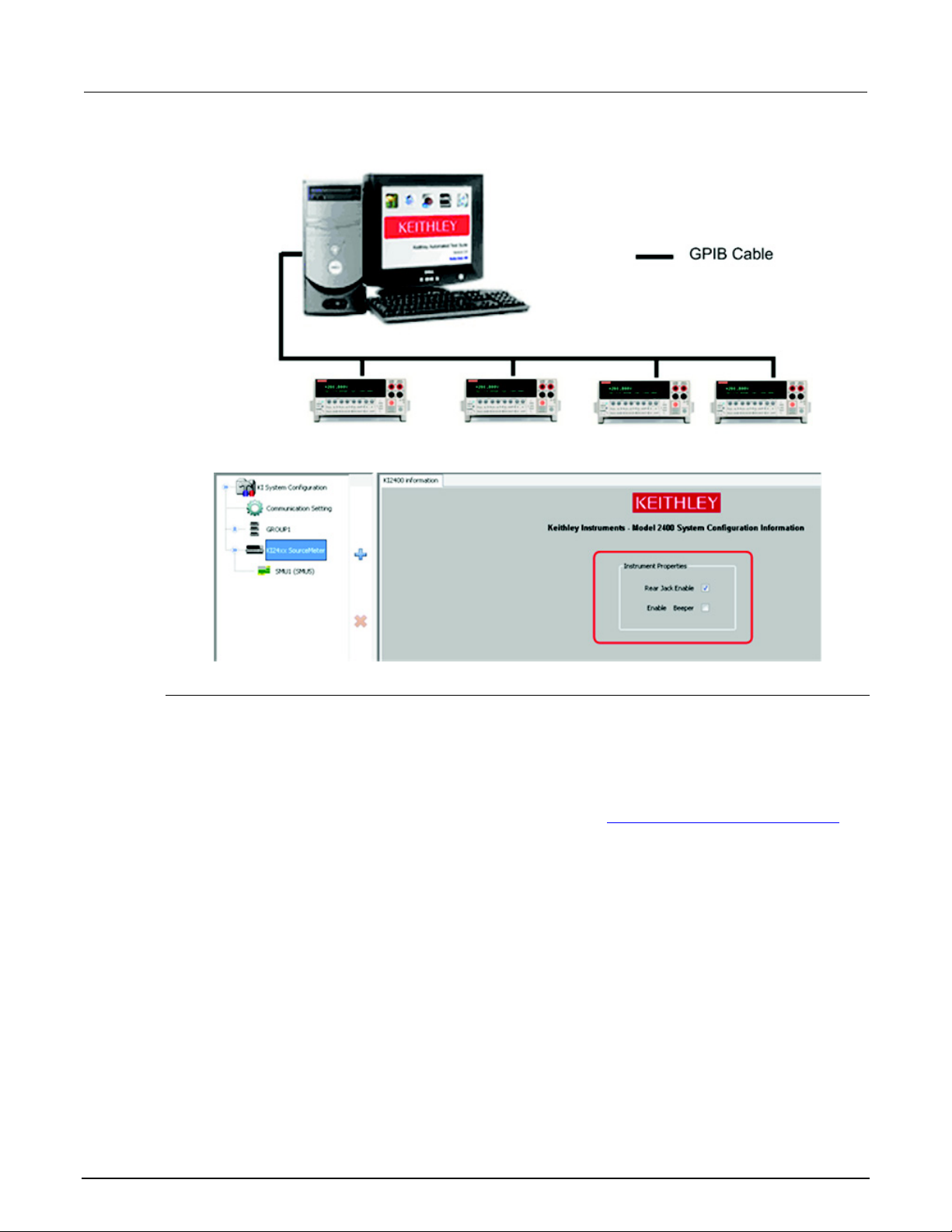
Series 2400 instruments can only be connected with a GPIB cable (see next figures):
1. Set a unique GPIB address for each instrument.
2. Connect the GPIB cables to each instrument, daisy chaining the connectors.
3. Start ACS Basic.
4. Open the hardware configuration GUI, and set the instrument properties: Rear Jack and Beeper.
For details on how to configure the GPIB address of the Series 2400 SourceMeter instruments, refer
to the Series 2400 SourceMeter manual documentation.
ACSBASIC-901 Rev. E / August 2012 4-9
Page 44
Section
Reference Manual
4: ACS Basic hardware configuration ACS Basic Automated Characterization Suite
Figure 28: Multiple Model 2400 SMU connections
Figure 29: Model 2400 configuration GUI
Multiple TSP instruments
Multiple TSP instruments configured in one group or several groups are supported by ACS Basic.
Using TSP-Link
You can use TSP-Link to connect subordinate instruments to the master, while the master instrument
is connected to the computer through a GPIB or Ethernet cable. ACS Basic treats all instruments
connected with TSP-Link to a master as a single group (refer to Check the hardware configuration
).
To setup a group of instruments with TSP-Link do the following tasks:
• Connect one instrument to the GPIB or Ethernet interface.
• Connect other TSP-enabled instruments using TSP-Link, daisy chaining the TSP-Link cables
between the instruments.
• Assign a unique node number to each instrument.
• If using GPIB, the master instrument should be node 1; if using Ethernet, the instrument that is
connected directly to the PC should be node 1.
• Start ACS Basic and it will scan the hardware.
4-10 ACSBASIC-901 Rev. E / August 2012
Page 45
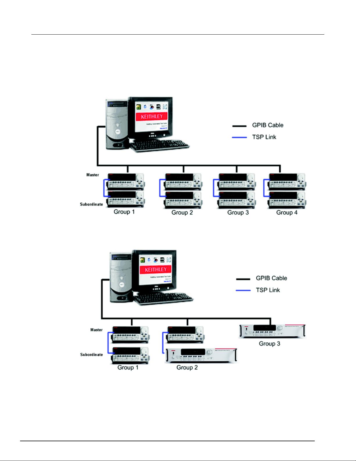
ACS Basic
ACS Basic hardware configuration
Automated Characterization Suite Reference Manual Section 4:
GPIB multiple interfaces
A group is connected through a GPIB cable (see next figure) from the controller to a Series
2600/2600B instrument which serves as the master node. The other instruments connected with
TSP-Link are subordinates of the master.
Figure 30: Multiple Model 2600 SMU connections
ACS Basic supports TSP groups containing different instruments, as shown the next figure which
depicts the Series 2600/2600B and Series 3700A instruments in multiple groups.
Figure 31: Multiple TSP instrument connections
ACSBASIC-901 Rev. E / August 2012 4-11
Page 46
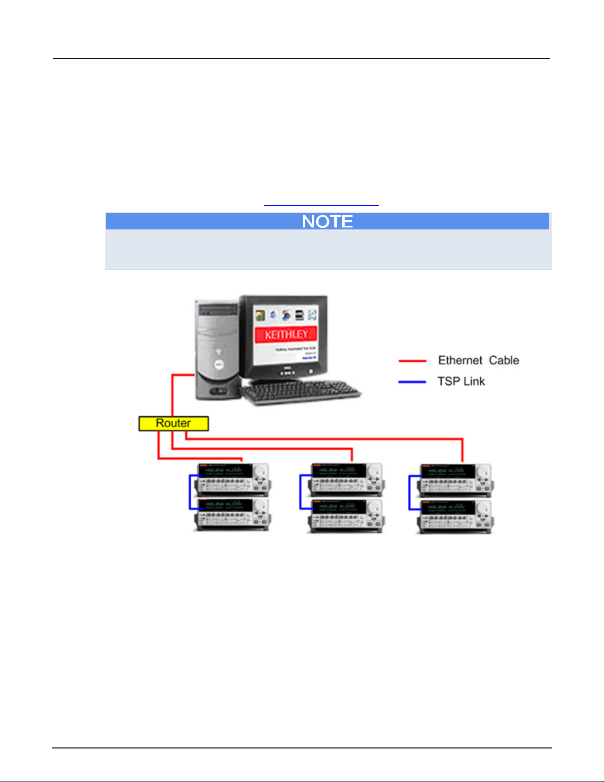
Section
Reference Manual
4: ACS Basic hardware configuration ACS Basic Automated Characterization Suite
Ethernet multiple interfaces
If you need to use multiple TSP-Link instrument groups connected by Ethernet, you can use an
Ethernet hub or a switch. Refer to the next two figures for Ethernet configuration connections.
• Connect the computer to the Ethernet hub or switch.
• Establish a unique IP address for the group master instrument.
• Connect all the instruments to the Ethernet hub or switch using Ethernet cables.
• Start ACS Basic and use the hardware configuration utility to add each IP address to the
hardware configuration (refer to Ethernet cable connection
For details on an Ethernet connection between a computer and master instrument, and the TSP-Link
connection between Series 2600B instruments, refer to the Series 2600B System SourceMeter
manuals.
Figure 32: Ethernet configuration #1
for more information).
4-12 ACSBASIC-901 Rev. E / August 2012
Page 47
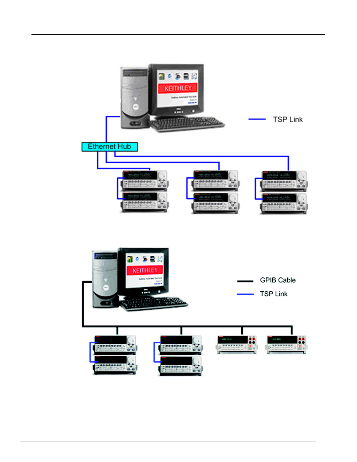
ACS Basic
ation
Automated Characterization Suite Reference Manual Section 4: ACS Basic hardware configur
Figure 33: Ethernet configuration #2
The next figure shows ACS Basic software installed on a computer and connected by GPIB cables to
Series 2600B and Series 2400 instruments.
Figure 34: Instrument connections configuration
ACSBASIC-901 Rev. E / August 2012 4-13
Page 48
Section
Reference Manual
4: ACS Basic hardware configuration ACS Basic Automated Characterization Suite
Connect to Model 4200-SCS SMUs
Instruments within Model 4200-SCS
ACS Basic will automatically scan the Model 4200-SCS hardware if ACS Basic is installed on the
Model 4200 and as long as the mode of communication is configured for Ethernet (see next figure).
Also, ACS Basic can control all of the hardware that is supported by the Model 4200-SCS.
Model 4200-SCS and KCON
Connect the 4200-SCS to the ACS Basic computer through a network connection. Record the IP
address of the Model 4200 for reference.
Before configuring a Model 4200 ITM, check to ensure that the Ethernet link is working. If you are
running ACS Basic on a local Model 4200 using the default 4200 IP address, your hardware
configuration is complete.
4-14 ACSBASIC-901 Rev. E / August 2012
Page 49
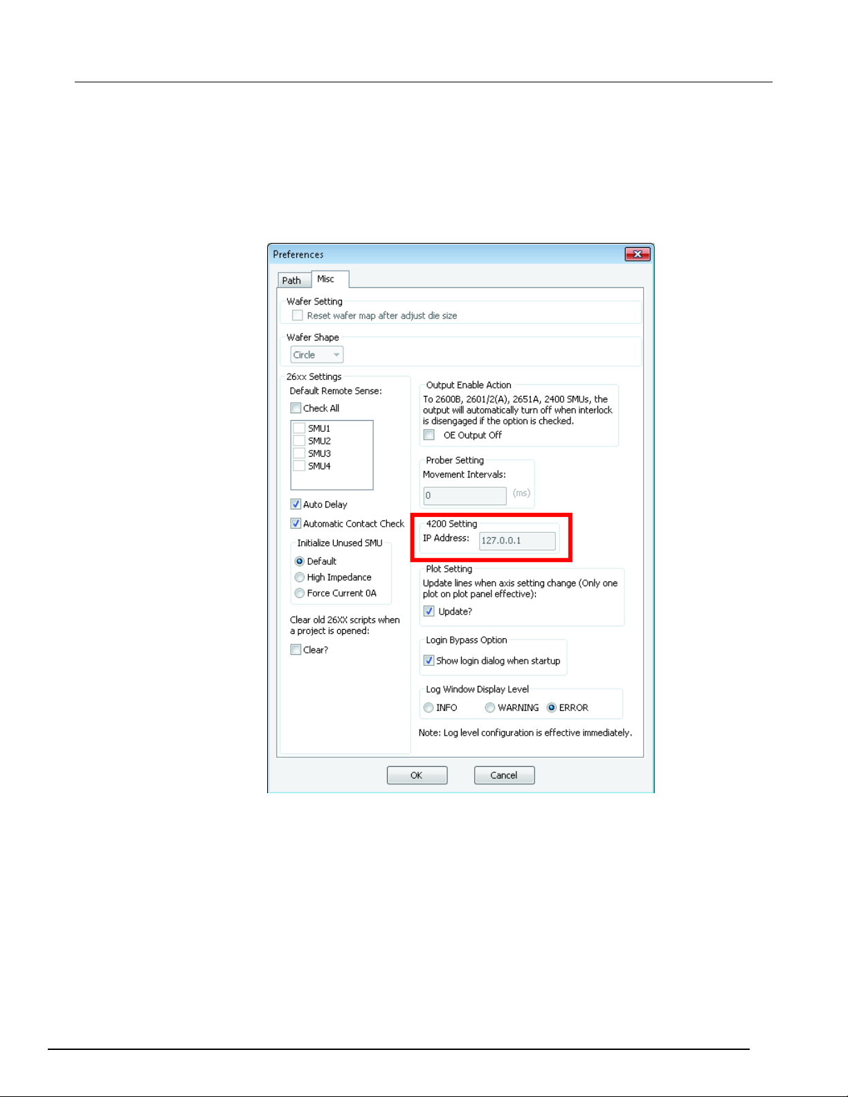
ACS Basic
ACS Basic hardware configuration
Automated Characterization Suite Reference Manual Section 4:
Set up the Model 4200-SCS in the ACS Basic preference menu:
On the toolbar, click on Tools, and from the drop-down list select Preferences ; the Preferences
dialog box opens.
a. Enter the Model 4200 IP address in the IP Address edit box (see next figure).
b. Click OK.
Figure 35: Set Model 4200-SCS IP address
ACSBASIC-901 Rev. E / August 2012 4-15
Page 50
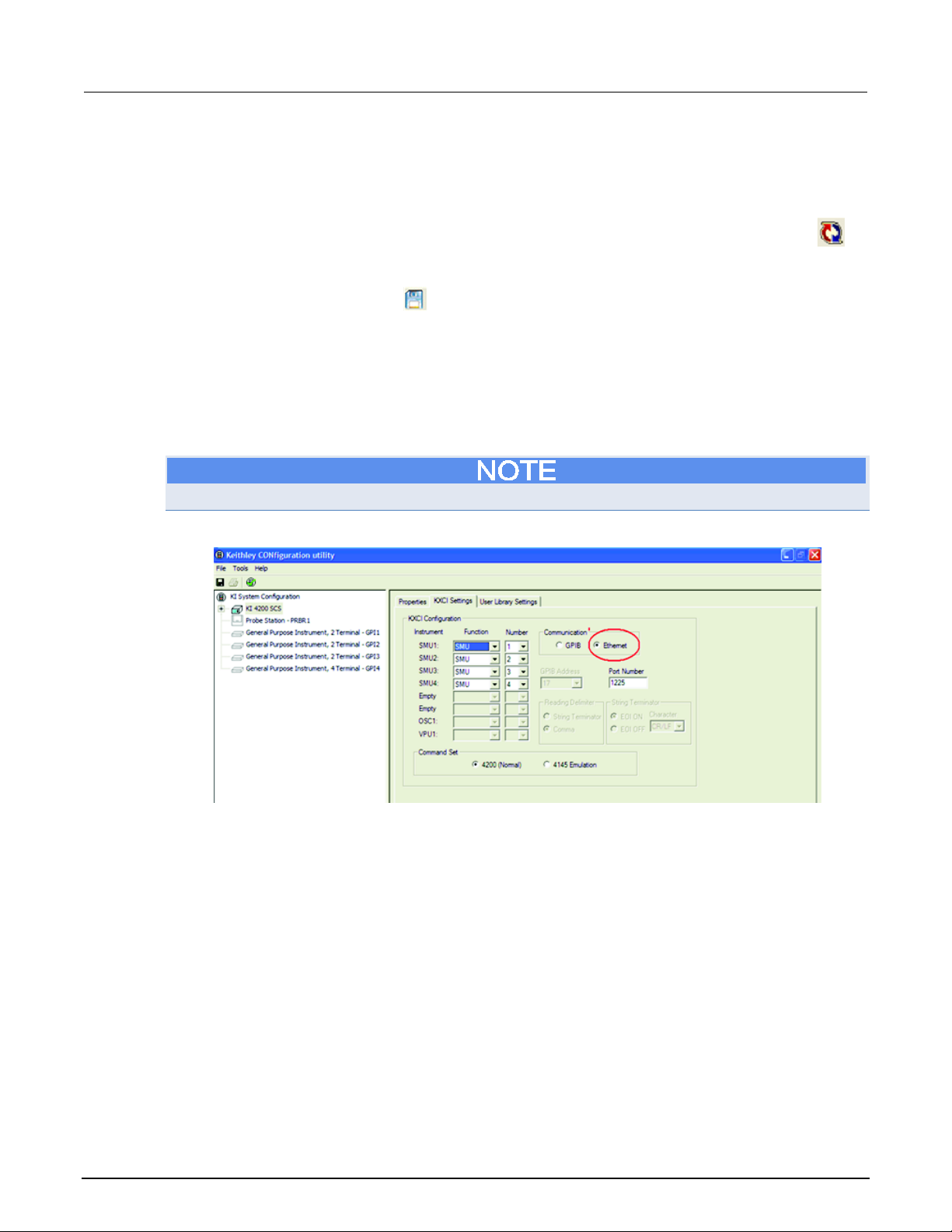
Section
Reference Manual
4: ACS Basic hardware configuration ACS Basic Automated Characterization Suite
Close and restart ACS Basic.
Check the hardware configuration:
Select the Configure Hardware option from the Tools drop-down list.
a. If the Model 4200 is not displayed in the navigation tree, click the Scan hardware icon on
the toolbar. The system queries the instruments and then opens the updated configuration
information in the configuration navigator.
b. Click the Save icon
c. Close and restart ACS Basic after the new configuration is saved.
.
Set the Model 4200-SCS communication mode using Keithley Configuration Utility (KCON) software:
• Open the KCON application on the Model 4200-SCS. The mode of communication with the Model
4200 should be set to Ethernet. You can verify the communication mode by opening KCON and
open the KXCI Settings tab (see next figure). Also, the communication mode is visible in the
KXCI message area.
The Model 4200 can only be used in Ethernet mode with ACS Basic.
Figure 36: Set Model 4200-SCS communication mode
• Start ACS Basic and it scans the hardware using KCON.
4-16 ACSBASIC-901 Rev. E / August 2012
• Check the scanned information in the ACS Basic hardware configuration navigator.
Page 51
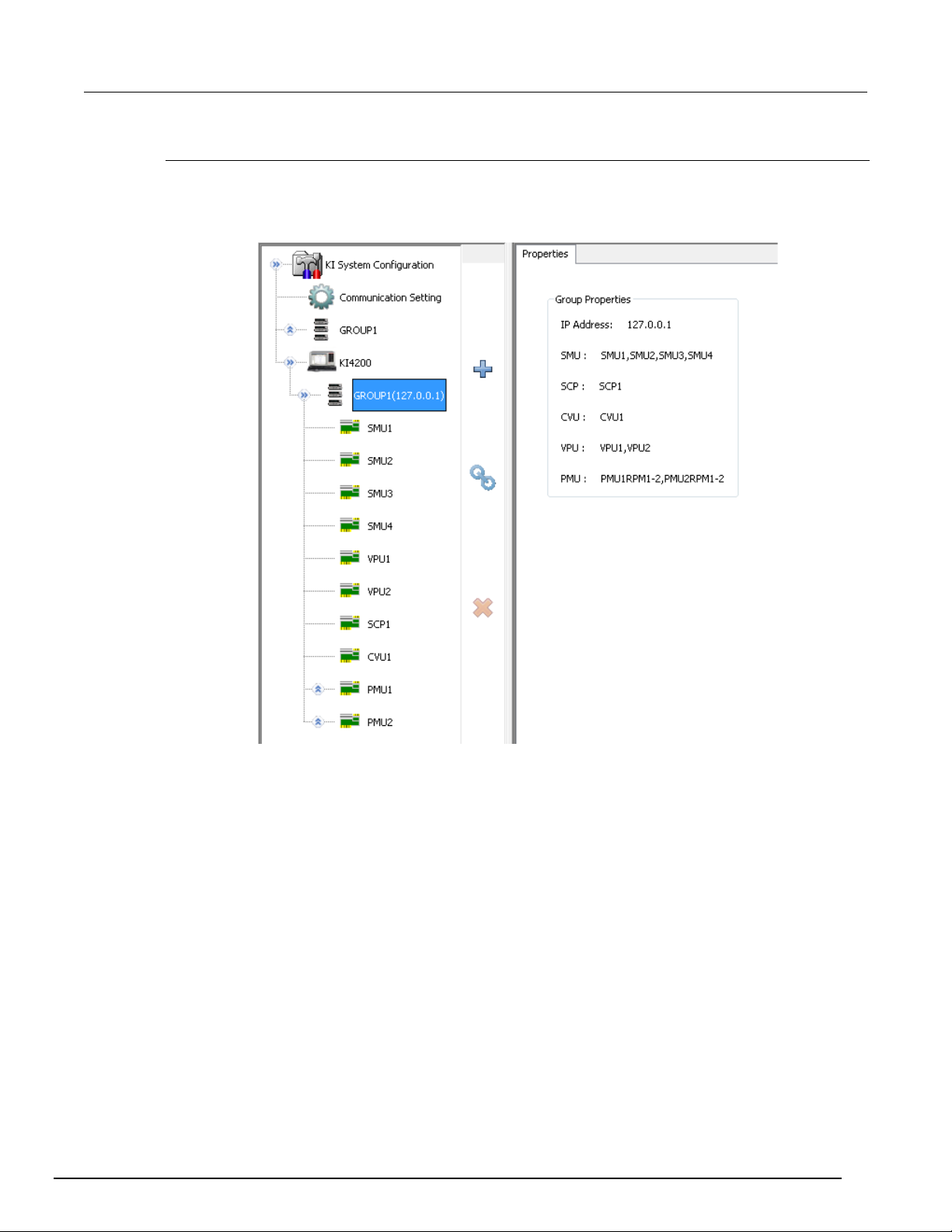
ACS Basic
ACS Basic hardware configuration
Automated Characterization Suite Reference Manual Section 4:
Model 4200 System properties
Click on the KI 4200-SCS icon in the configuration navigator and the properties are displayed in the
work area (see next figure).
Figure 37: Model 4200 group properties
ACSBASIC-901 Rev. E / August 2012 4-17
Page 52
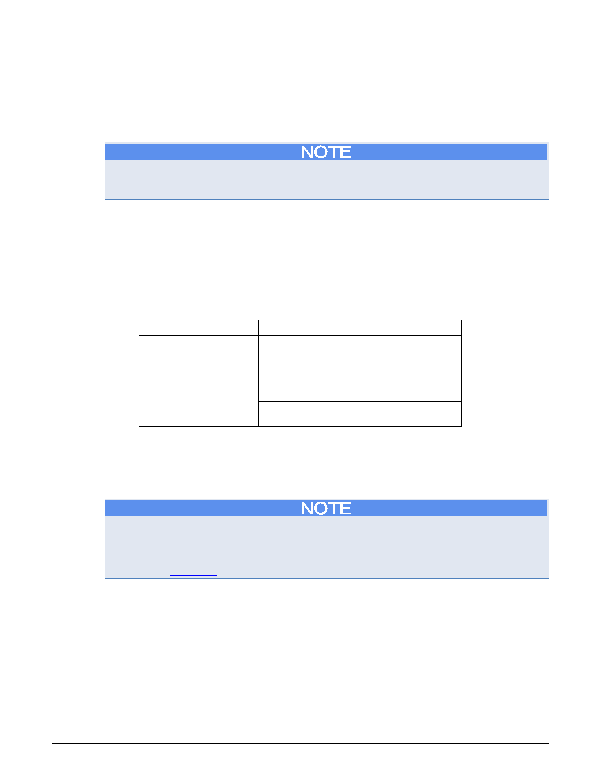
Section
Reference Manual
Model 707/707A (or 707B in DDC mode) Switching
Matrix
Model 708/708A (or 708B in DDC mode) Switching
Matrix
Capacitance Meter2
Model 4284/4980 CMTR
General purpose test
Other source meters (such as Model 237)
4: ACS Basic hardware configuration ACS Basic Automated Characterization Suite
Connect to external instruments
ACS Basic can communicate with other external instruments using the hardware configuration utility.
However, all external instruments can only be controlled over GPIB.
External instruments are not automatically scanned when ACS Basic is started and, they cannot be
scanned if you use the scan hardware function. This means that all external instruments must be
configured manually on the Hardware Utility Configuration GUI.
The supported external instrument categories are:
• Switch Matrix
• Capacitance Meter
• General Purpose Test Instrument
All supported external instrumentation and equipment are run by Python Test Modules (PTMs)(see
Configure a PTM for more information).
The next table lists the supported external instruments.
Category Instrument
Switch matrix1
instrument3
1
ACS Basic supports the Keithley Instruments Model 707/707A/707B and 708/708A/708B Switch Matrices. The Model 708/708A/708B
accepts a single matrix card. The Model 707/707A/707B accepts up to six matrix cards. Also, models 707B and 708B have two working
modes: DDC (same as 707A/708A) and ICL. In ICL mode, these instruments can be connected using Ethernet or TSP-Link.
2
Up to four supported capacitance meters can be added to the system configuration.
3
ACS Basic supports up to 16 general purpose test instruments (GPIs). Two-terminal and four-terminal types can be in the system
configuration simultaneously, but the total number of GPIs cannot exceed 16.
Any IEEE-488 controlled instrument or equipment
ACS Basic provides Python LPT libraries for each supported external instrument. You can use these
libraries to create your own test modules. ACS Basic also provides a number of standard Python user
libraries to control external equipment that is typically used in semiconductor characterization
applications. Standard user-module libraries are provided for equipment that can be used with ACS
Basic (refer to Test Setup for more information).
4-18 ACSBASIC-901 Rev. E / August 2012
Page 53
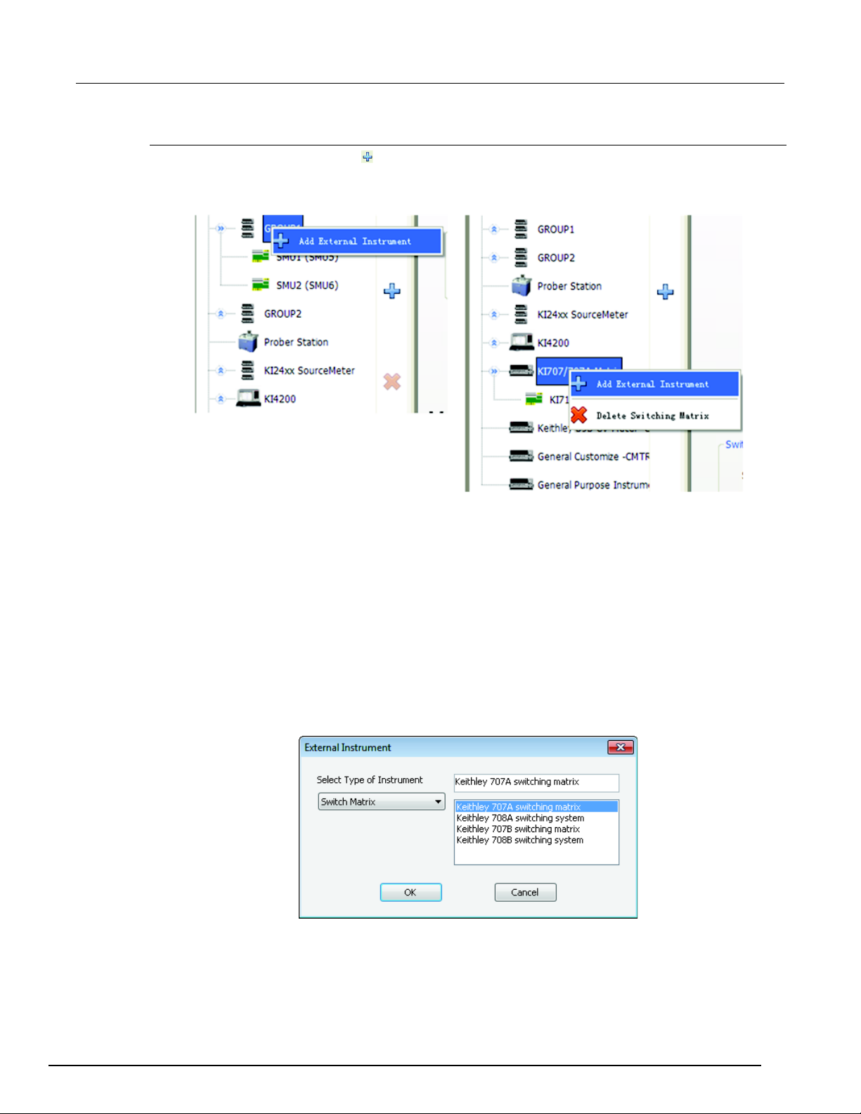
ACS Basic
ACS Basic hardware configuration
Automated Characterization Suite Reference Manual Section 4:
Add an external instrument
1. Click the add instrument icon , or right-click the instrument node in the configuration navigator,
and click the pop-up item (see next figure).
Figure 38: Add an external instrument
2. After clicking the Add External Instrument option, you will see the External instrument dialog box.
In this dialog box you can choose the type of instrument to add (see next figure).
3. Select the instrument that you have in your hardware configuration and click OK to accept or click
Cancel to exit the dialog without making any changes.
Add a switching matrix
From the Select Type of Instrument drop-down list select Switch Matrix and a list of supported switch
matrix instruments appears in the list box on the right (see next figure). The following switch matrix
instruments are supported by ACS Basic:
• Model 707A/707B switching matrix
• Model 708A/708B switching system
Figure 39: Select switch Matrix
ACSBASIC-901 Rev. E / August 2012 4-19
Page 54
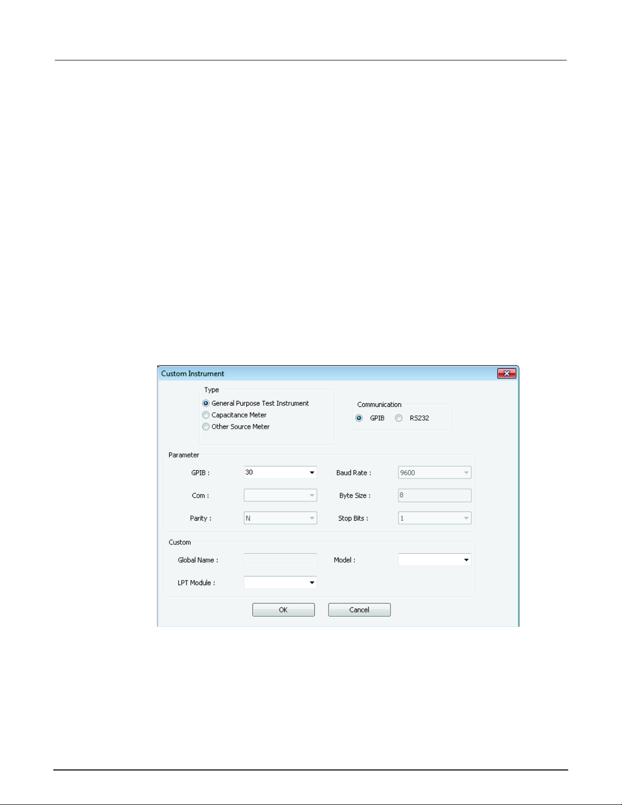
Section
Reference Manual
4: ACS Basic hardware configuration ACS Basic Automated Characterization Suite
Add a capacitance meter
From the Select Type of Instrument drop-down list select Capacitance Meter and a list of supported
capacitance meters appears in the list box on the right. The following capacitance meters are
supported by ACS Basic:
• Keithley 590 CV Analyzer
• Keithley 595 Quasistatic CV Meter
Add a general purpose instrument
From the Select Type of Instrument drop-down list select General Purpose Instrument (GPI) and a list
of supported general purpose instruments appears in the list box on the right. The following general
purpose instruments are supported by ACS Basic:
• Generic 2 Terminal GPI
• Generic 4 Terminal GPI
• Custom GPI
Custom GPI
If you selected Custom GPI, the custom instrument window opens where you must input some basic
information (see next figure):
Figure 40: Custom Instrument dialog box
4-20 ACSBASIC-901 Rev. E / August 2012
Page 55
ACS Basic
ACS Basic hardware configuration
Automated Characterization Suite Reference Manual Section 4:
• Select the type of custom instrument:
• General Purpose Test Instrument: some custom instruments, including those instruments from other
companies.
• Capacitance Meter: supports AG4284 or AG4980 capacitance meter.
• Other Source Meter: supports Model 236/237/238 SMU.
• Select the communication:
• GPIB
• RS232
• Define parameters associated with the chosen communication.If you select General Purpose Test
Instrument, then enter the model name. If you select Capacitance Meter or Other Source Meter,
then use the drop-down list in the Model field to select the instrument Model.
• Select the LPT Module. The LPT Module refers to the LPT libraries that are installed in ACS
Basic. For the General Purpose Test Instrument, you will not have to add an LPT module.
There are LPT libraries installed when you install ACS Basic. After installation, the Python LPT
libraries are saved in the folder: (C:\ACS_Basic\library\pyLibrary\ptmlpt). ACS Basic supplies these
LPT library packages: ki23xlpt, ki24xxlpt, ki26xxlpt, ki34xxlpt, ki37xxlpt, ki42cvulpt, ki42xxlpt, ki70xlpt,
ki70xblpt, kiag4284lpt. For the external instrument, such as Model 236, 237, HP4284, you can select
the corresponding LPT.
Delete an external instrument
Delete an external instrument to remove the instrument from the hardware configuration.
Only an external instrument can be deleted (using the delete icon ) from the hardware
configuration navigator.
• Right-click on the external instrument that you want to remove in the configuration navigator, then
click the delete external instrument function.
• Alternatively, you can delete an external instrument by selecting it and then click the delete icon
in the software.
Save the hardware configuration
The Save icon on the toolbar of Hardware Configure GUI is enabled when you modify any
configurable properties. Click the Save icon
You must close and restart ACS Basic after you make a change to the hardware configuration or the
new configuration will not be functional.
to save your changes.
ACSBASIC-901 Rev. E / August 2012 4-21
Page 56
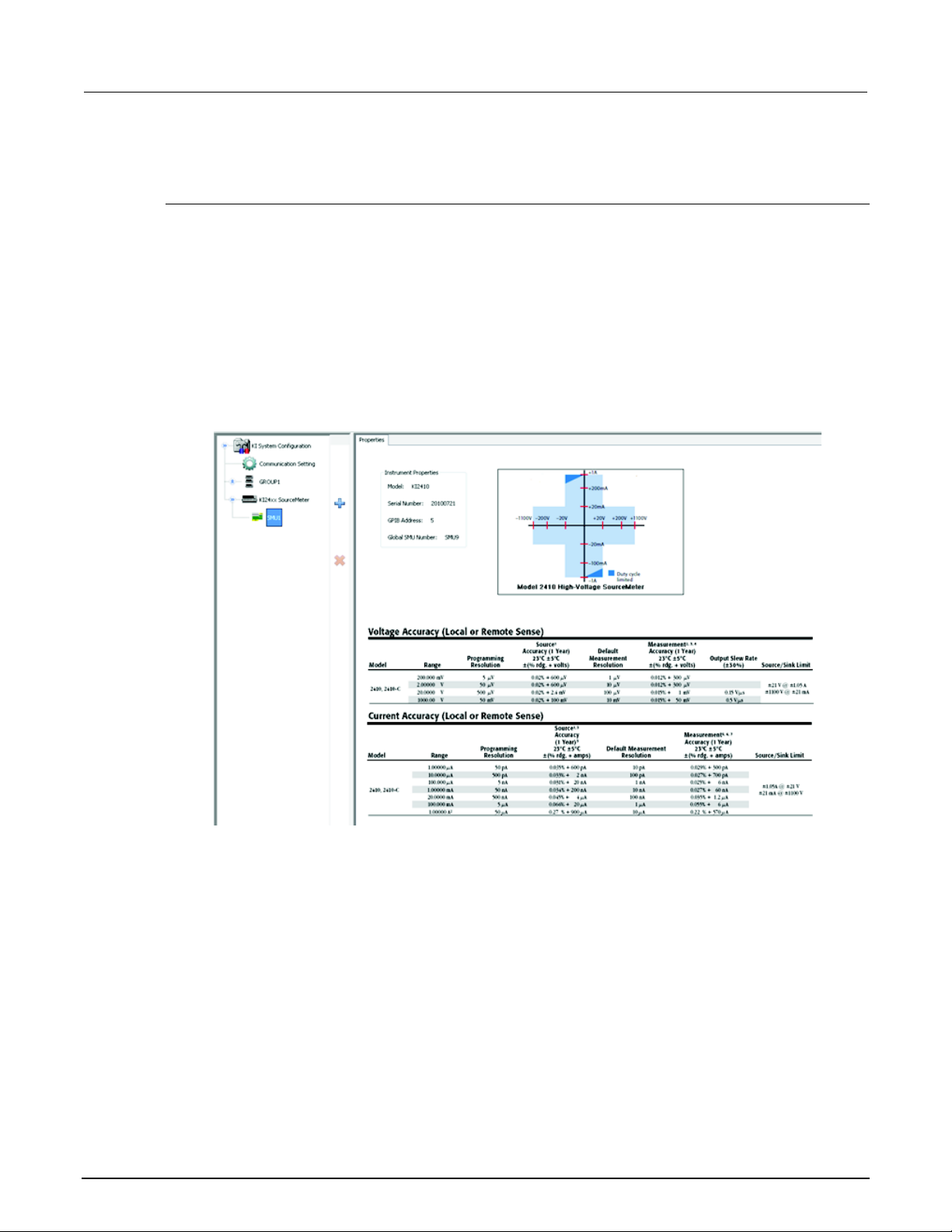
Section
Reference Manual
4: ACS Basic hardware configuration ACS Basic Automated Characterization Suite
View and setup instrument properties
Series 2600B system properties
Single configuration: When the node of a Series 2600B instrument on the configuration navigator is
selected, the work area displays an overview of the instrument(s).
Group configuration: When the node of GROUPx on the configuration navigator is selected, the
work area displays the groups’ GPIB address and configuration.
SMU configuration: When the node of a Series 2600B SMUx on the configuration navigator is
selected, the work area shows the SMU properties, specifications, and power capacity (see next
figure).
Example: Model 2651A
Figure 41: Model 2651A information
The Model of the SMU is displayed in the first line. The SMU offset information displays in the second
line: SMU A corresponds to offset=0; SMU B corresponds to offset=1. The next three lines display the
SMU node number, its hardware version, and serial number. The last two lines display the calibration
date. The first is the last time the SMU was calibrated, while the second is the scheduled date when
the SMU should be calibrated.
4-22 ACSBASIC-901 Rev. E / August 2012
Page 57
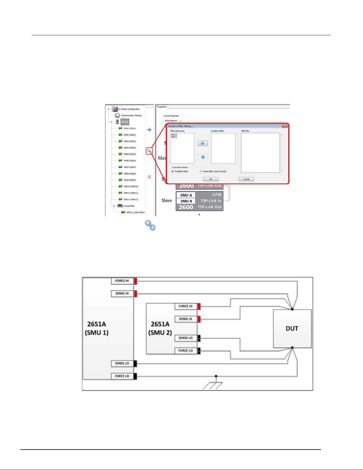
ACS Basic
ACS Basic hardware configuration
Automated Characterization Suite Reference Manual Section 4:
Composite SMU
ACS Basic enables you to combine two 2651A SMUs in parallel as a single SMU. This will give you
the capability to output 100 amps of current, or use in series for an 80 volt output. In the configuration
navigator, the combined 2651A SMUs are considered a composite SMU. The work area will show the
properties for the composite SMU.
Figure 42: Combine two 2651A SMUs
Click the Combine SMUs icon and a dialog box opens where you choose the SMUs to combine
(only two 2651A SMUs can be combined) and where you choose the Connection Mode (see previous
figure):
1. Parallel (100A). Two 2651A SMUs are in parallel for higher current output. The composite SMU is
named SMUx_100A (x represents the SMU number).
Figure 43: Parallel (100A) composite SMU connections
ACSBASIC-901 Rev. E / August 2012 4-23
Page 58
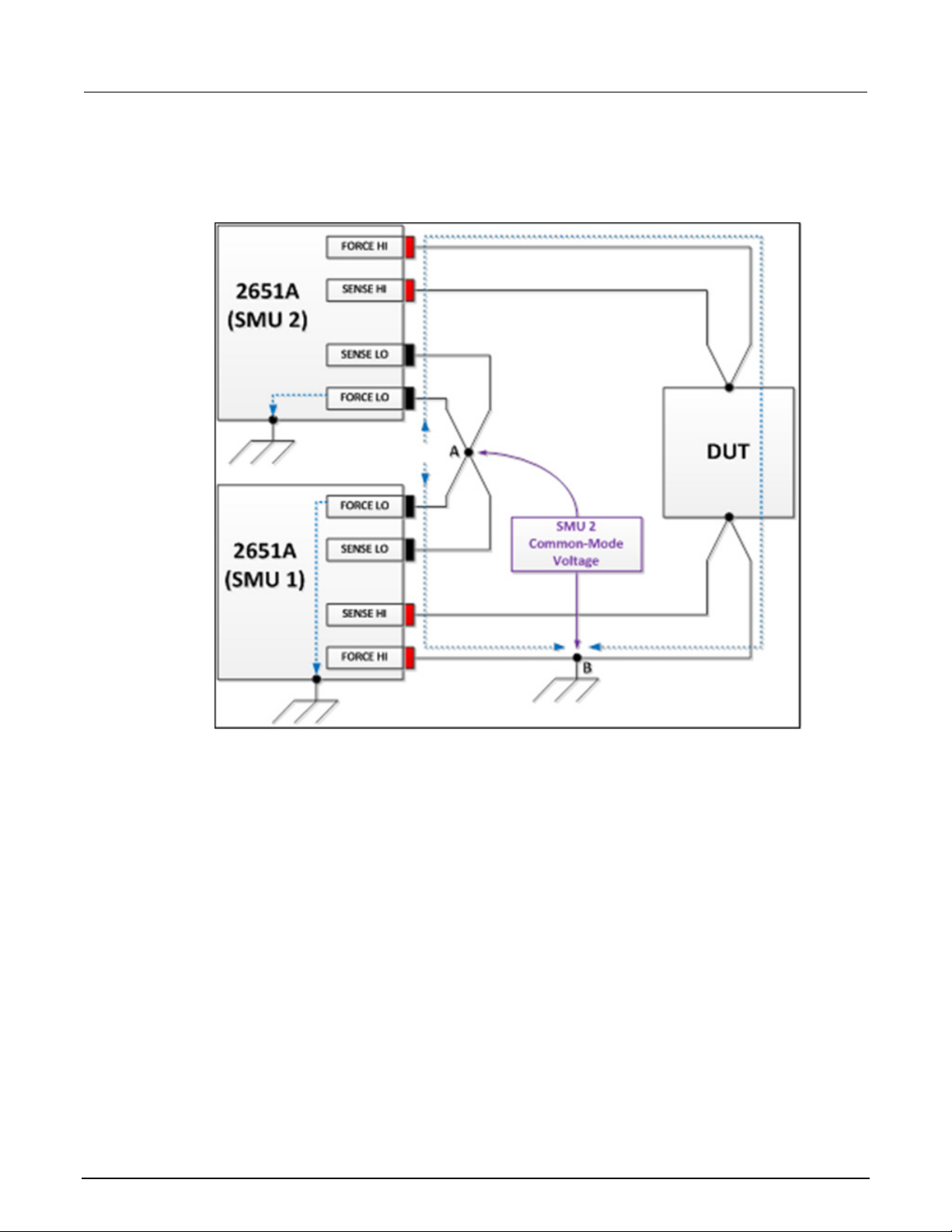
Section
Reference Manual
4: ACS Basic hardware configuration ACS Basic Automated Characterization Suite
2. Series (80V, back to back). Two 2651A SMUs are in back-to-back series for a higher voltage
output. The composite SMU has two terminals: SMUx_80V_HI and SMUx_80V_LO (x represents
the SMU number).
Figure 44: Series 2650A composite SMU connections
4-24 ACSBASIC-901 Rev. E / August 2012
Page 59
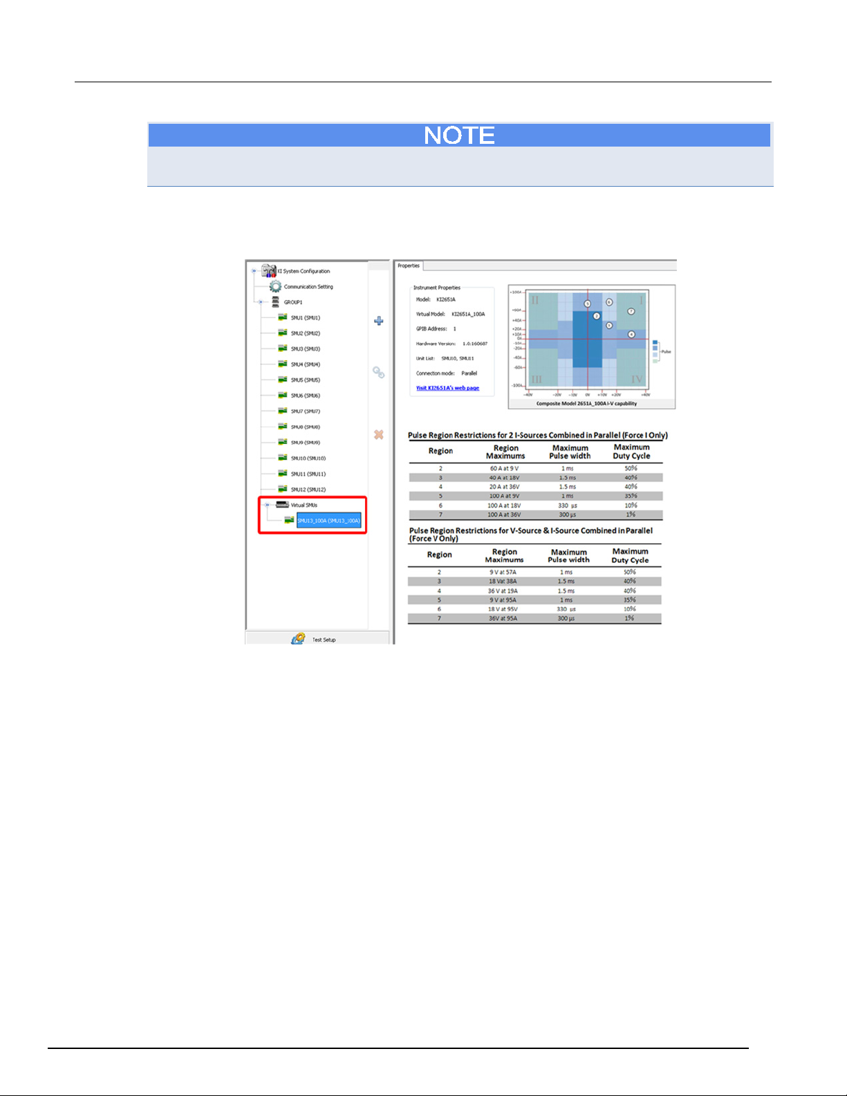
ACS Basic
ACS Basic hardware configuration
Automated Characterization Suite Reference Manual Section 4:
The parallel (100A) SMU can be used in an ITM and trace mode for certain modules. The series
2650A (80V, back to back) SMU can only be used in a 2-terminal device in trace mode.
In the configuration navigator, the composite SMU is labeled "Virtual SMUs" (see next figure). The
properties of the composite SMU are displayed in the work area.
Figure 45: Virtual SMUs
ACSBASIC-901 Rev. E / August 2012 4-25
Page 60
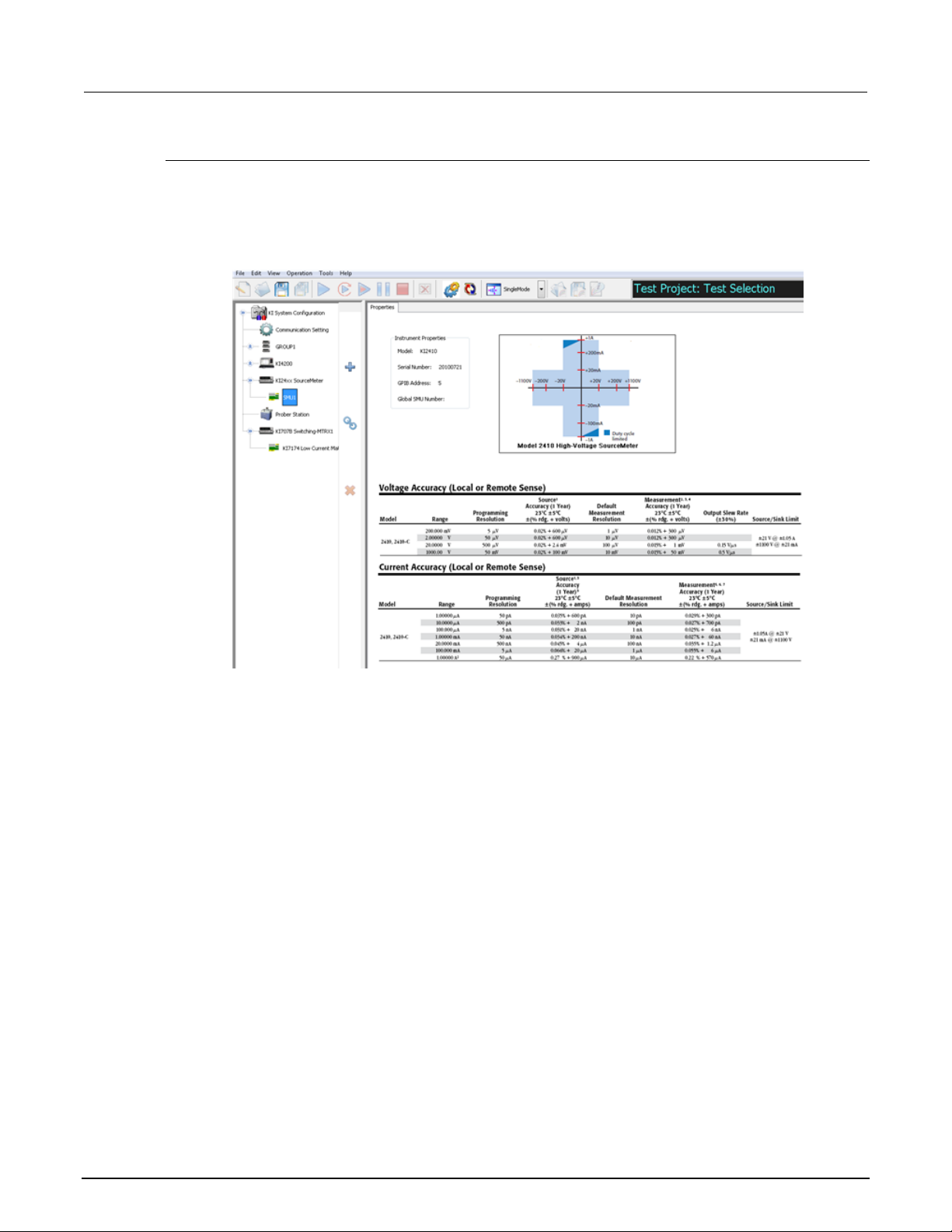
Section
Reference Manual
4: ACS Basic hardware configuration ACS Basic Automated Characterization Suite
Series 2400 system properties
Series 2400 SMU configuration
When a Series 2400 SMUx node is selected in the configuration navigator, the work area shows the
SMU properties, specifications, and power capacity (see next figure).
Figure 46: Model 2400 SMU information
The instrument Properties area displays the following information:
• SMU Model
• SMU Serial Number
• GPIB Address
• Instrument name
4-26 ACSBASIC-901 Rev. E / August 2012
Page 61

ACS Basic
ACS Basic hardware configuration
Automated Characterization Suite Reference Manual Section 4:
Matrix instruments
Models 707A/707B and 708A/708B switch matrices
Models 707A, 707B, 708A, and 708B switch matrices can be added to the ACS Basic hardware
configurations as external instruments with GPIB connections. Models 707B and 708B can also be
automatically scanned and added to the configuration through the GPIB and TSP link as a master or
subordinate instrument.
Note that ACS Basic supports multiple matrices, such as Models 707A, 707B, 708A, 708B, and
Series 3700A instruments in the hardware configuration. Additionally, ACS Basic supports multiple
matrices as a group or as individual instruments.
ACS Basic also supports both device dependent command (DDC) mode and instrument control
language (ICL) mode for Models 707B and 708B:
• DDC mode instruments must be manually added to the hardware configuration
• ICL mode instruments are automatically scanned and added to the hardware configuration
Model 707B and 708B configuration
When a Model 707B or 708B node is selected in the configuration navigator, the instrument
Properties, Instrument Connection Scheme, and specifications are viewable in the work area.
The Model 707B or 708B Properties tab contains:
• Instrument Properties:
• model of instrument
• associated group (ICL mode)
• node (ICL mode)
• work mode (ICL or DDC)
• card list (ICL mode)
• GPIB address (DDC mode).
• S530 System: Kelvin mode enabled or disabled (Model 707A/707B only).
• Instrument Connection Scheme:
• Row-Column or Instrument-Card
• Local Sense or Remote Sense
• Common LO or Independent LO
• Switch Card: select matrix cards for the system (see next figure):
• Model 7071 Matrix Card
• Model 7072 Matrix Card
• Model 7072 HV Matrix Card
• Model 7136 Low Current MUX Card
• Model 7174 Low Current Matrix Card
• Model 9174 Semiconductor Matrix Card
ACSBASIC-901 Rev. E / August 2012 4-27
Page 62
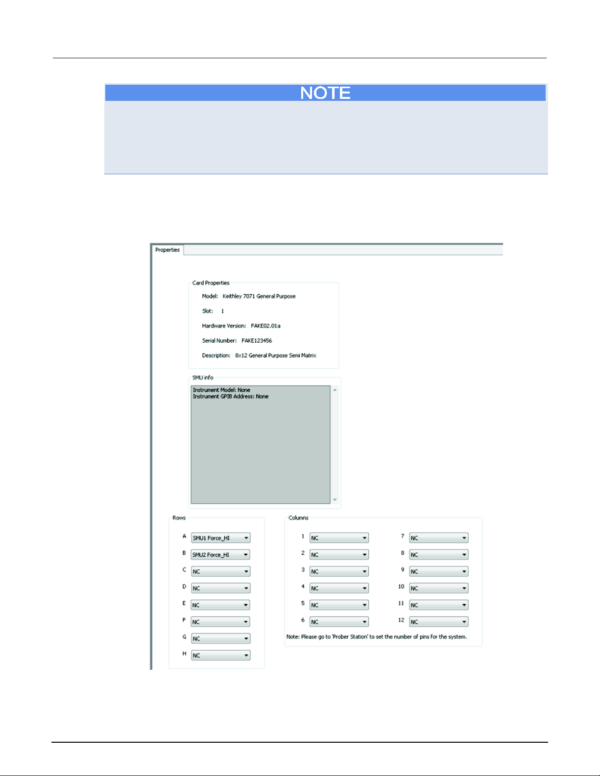
Section
erence Manual
4: ACS Basic hardware configuration ACS Basic Automated Characterization Suite Ref
If any of the matrices in the system are set to Remote Sense or the S530 Kelvin mode, all of the
Series 2600B and Series 2400 instruments in the system will be set to four-wire (4-W) mode when
executing a test. Also, the SMU Remote Sense option box in the Preference settings Misc tab will be
disabled. When all the matrices are set to Local Sense, all of the Series 2600B and Series 2400
instruments in the system will be set to two-wire (2-W) mode when executing a test. It is highly
recommended that all the matrices in the system are in the same mode.
Matrix Card information
When you click one of the matrix cards on the hardware configuration navigator, a GUI dialog box
opens. The GUI is where you configure the hardware (see next figure).
Figure 47: Model 7071 matrix card properties
4-28 ACSBASIC-901 Rev. E / August 2012
Page 63
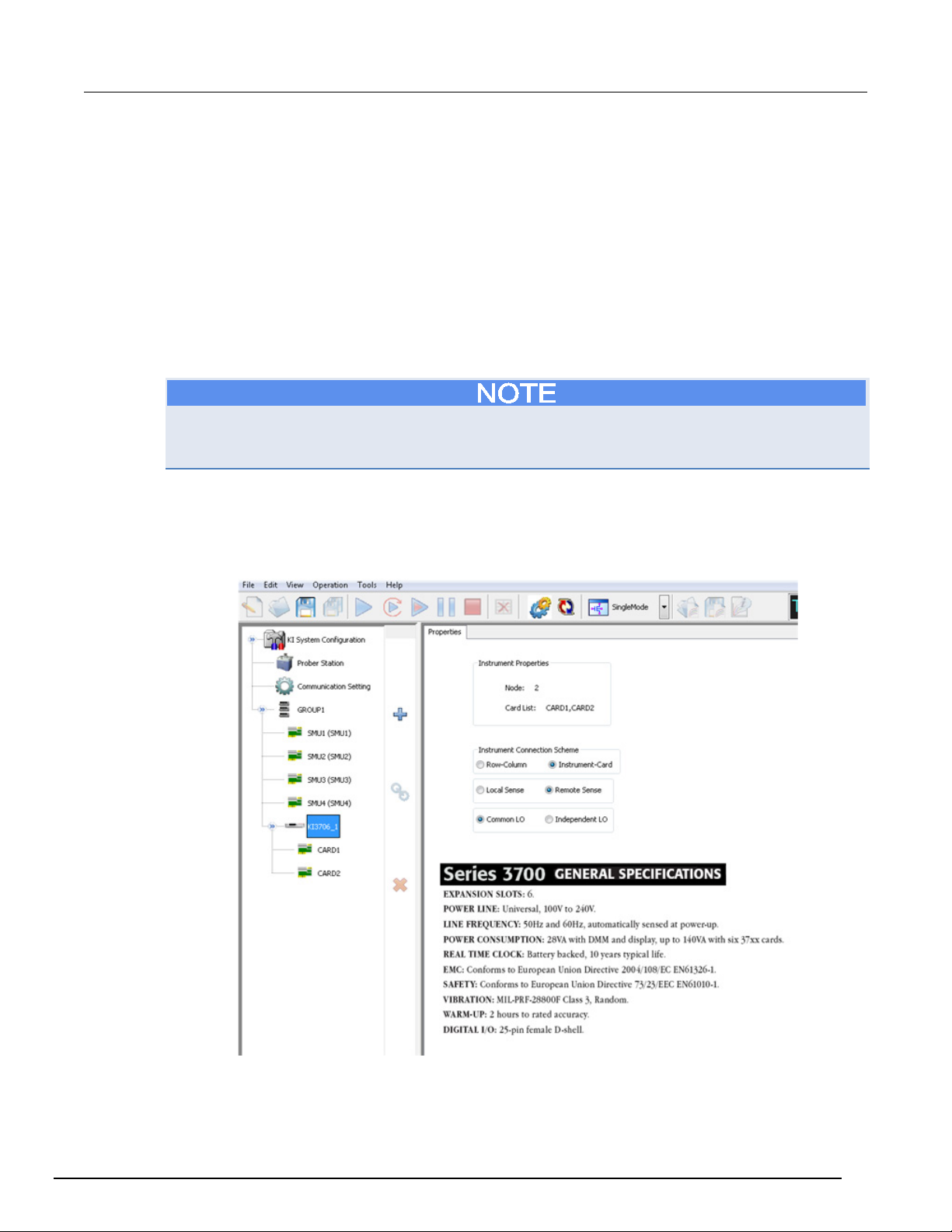
ACS Basic
ACS Basic hardware configuration
Automated Characterization Suite Reference Manual Section 4:
The Matrix Card Properties tab contains:
• Card Properties: instrument model, slot number, hardware version, serial number, and the
description of the card.
• SMU info: instrument model, GPIB address, maximum voltage and current, voltage and current
range.
• Rows: A through H correspond to the eight (8) rows of all Model 707B/708B compatible matrix
cards. Use the drop-down arrow to connect the rows to various instrument terminals.
• Columns: one through 12 correspond to columns for the Model 707B/708B compatible matrix
cards. Use the drop-down arrows to connect the columns to various instrument terminals or
prober test-fixture pins, or any combination of both terminals and prober pins depending on your
needs.
Due to the Model 2651A high current SMU (up to 50A), and the Model 2657A high power SMU (up to
3000V), you will not be able to add a Model 2651A SMU and a Model 2657A SMU to the matrix card
row or column.
Model 3706A configuration
When a Model 3706A node is selected in the configuration navigator, the work area shows the
Properties, Instrument Connection Scheme, and specifications (see next figure).
Figure 48: Model 3706 information
ACSBASIC-901 Rev. E / August 2012 4-29
Page 64
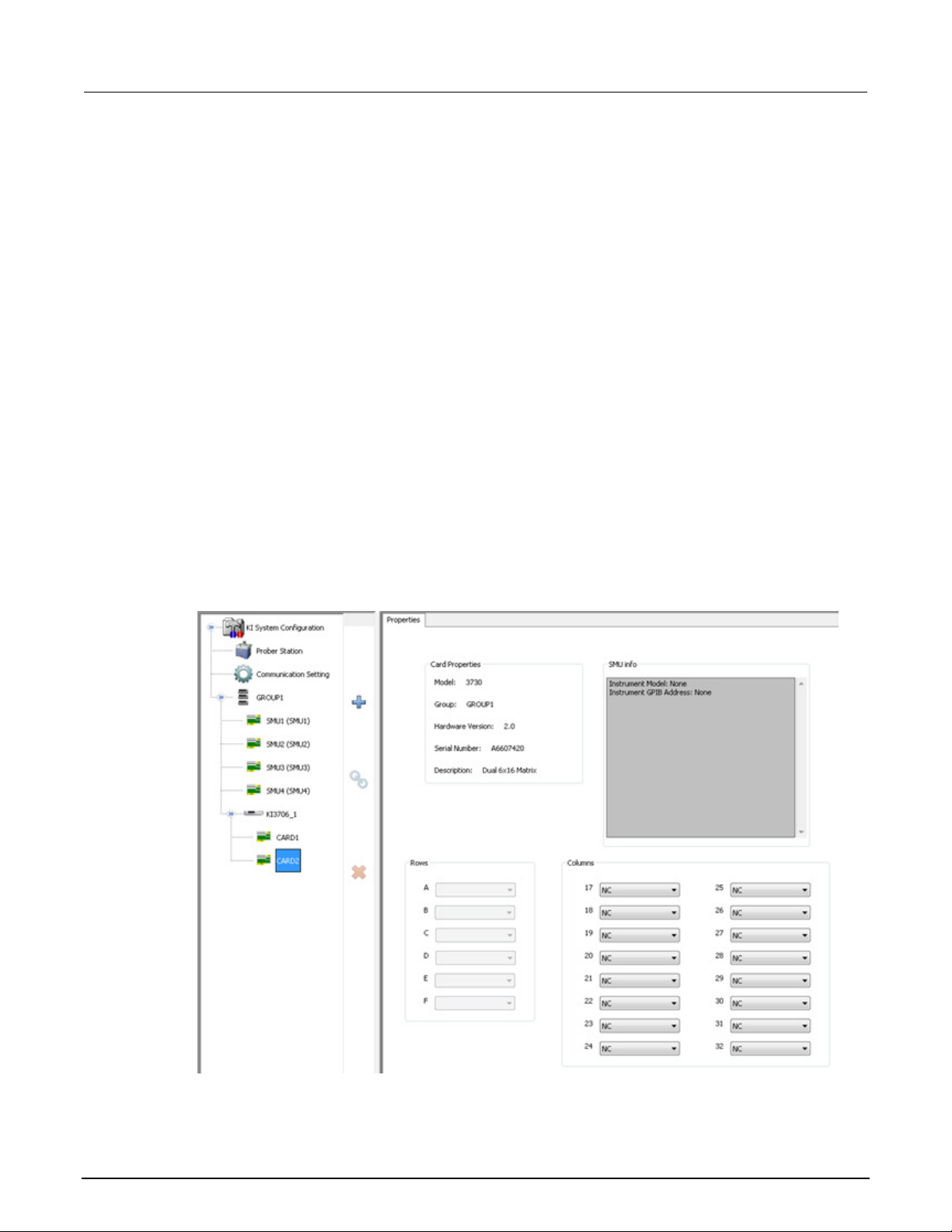
Section
Reference Manual
4: ACS Basic hardware configuration ACS Basic Automated Characterization Suite
A Model 3706A Properties tab contains the following:
• Instrument Properties: displays the node and the two types of cards: multiplexer or matrix.
The following Instrument Connection Scheme selections define the scheme for interconnections
between the instruments, the switch matrix rows and columns, and the test system (prober or test
fixture).
• Row-Column (instruments to rows and prober/test fixture to columns) or Instrument-Card (both
instrument and prober/test fixture to columns).
• Local Sense (connections only to the instrument FORCE terminals) or Remote Sense
(connections to both the instrument FORCE and SENSE terminals).
• Series 3700A General Specifications: displays the information about the specifications.
Series 3700A: multiplexer card
The next figure shows two cards are inserted in a Series 3700A instrument. They are the multiplexer
card (CARD1) and the switch card (CARD2). When the multiplexer (CARD1) node is selected, the
work area shows the properties and specifications for the multiplexer (CARD1).
The Card Properties group box of a multiplexer card contains information about the model, group,
hardware version, serial number, and description. Specifications for the card are also listed.
Series 3700A: matrix card
When the matrix card (CARD2) node is selected, the work area shows the properties and connection
options that are defined for the device (see next figure).
Figure 49: Matrix card information
4-30 ACSBASIC-901 Rev. E / August 2012
Page 65
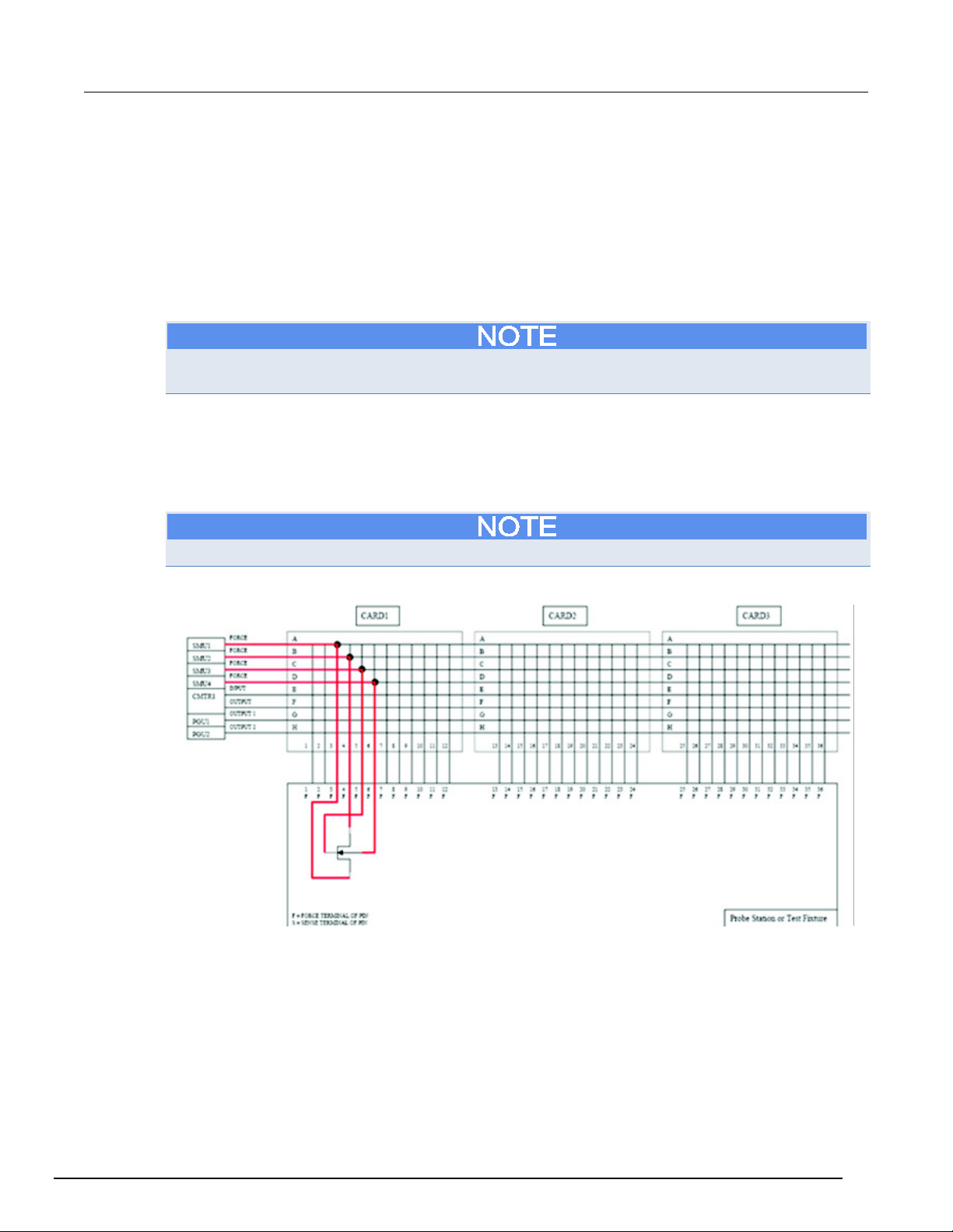
ACS Basic
ACS Basic hardware configuration
Automated Characterization Suite Reference Manual Section 4:
The Card Properties area contains information about the model, group, hardware version, serial
number, and description. There is also a SMU info area, and two additional areas that provide
information about the connection method:
1. Rows: In the Rows area, the edit boxes labeled A through F correspond to the 6 rows for the
Model 3706A compatible matrix cards. Use the drop-down arrows to select the rows for your
instrument terminals.
2. Columns: In the Columns area, the edit boxes labeled 1 through 16 correspond to the 16 columns
for the Model 3706A compatible matrix cards. Use the drop-down arrows to select the columns
for your instrument terminals and/or prober/test-fixture pins.
You can only connect instrument terminals to the matrix card columns when the Instrument
Connection Scheme setting is active (see next figure).
Matrix instruments
Row-Column: instruments are connected to switch matrix rows, and prober/test fixture pins are
connected to switch matrix columns (see next figure). This is the simplest connection scheme.
Instrument signals can route to the prober/test-fixture pins through one matrix card. However, the
Row-Column scheme limits the number of external instruments.
Prober or test-fixture pins are always connected to matrix card columns.
Figure 50: Row-column, local sense connection scheme example
ACSBASIC-901 Rev. E / August 2012 4-31
Page 66
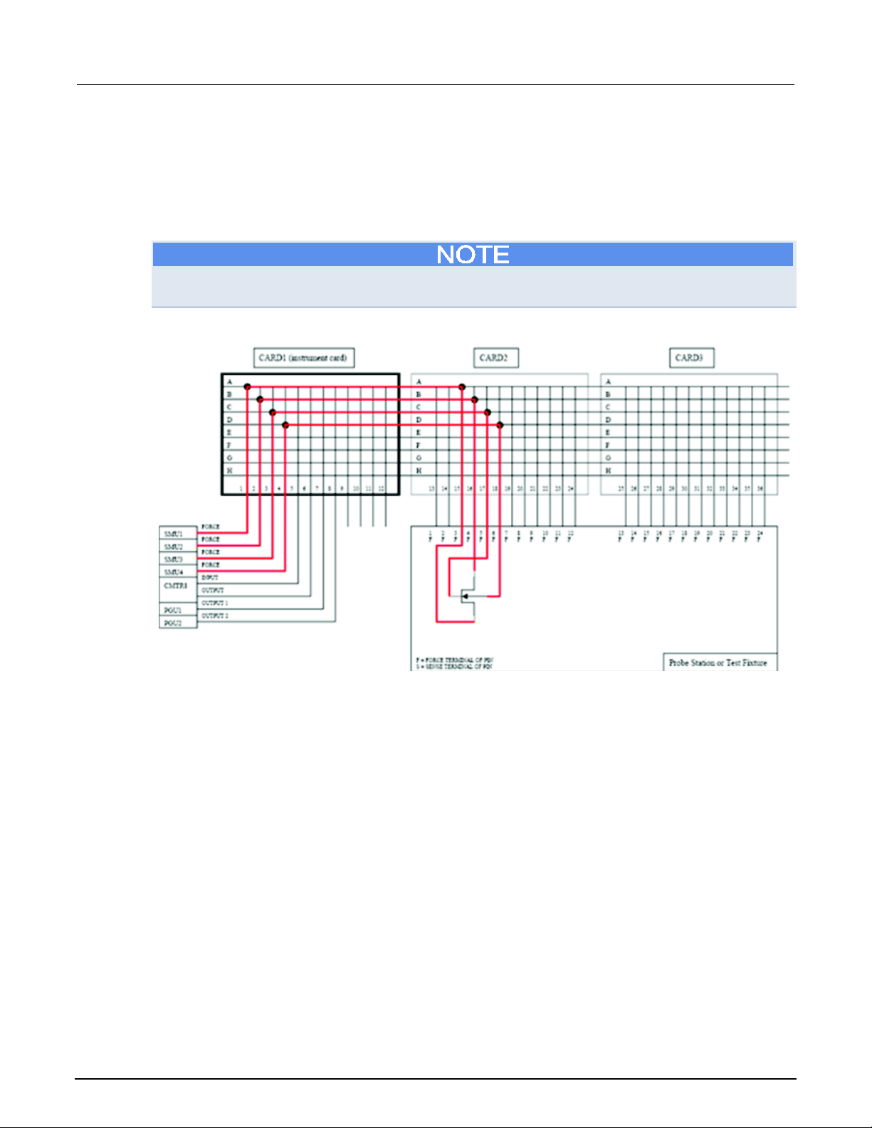
Section
Reference Manual
4: ACS Basic hardware configuration ACS Basic Automated Characterization Suite
If you need to connect multiple external instruments to the prober/test-fixture, use the Instrument
Card scheme.
Instrument Card: both instruments and prober/test-fixture pins are connected to the switch matrix
columns. Instrument signals can route to the prober/test-fixture pins through two or more matrix
cards. This connection scheme can support more instruments compared to the Row-Column scheme
(see next figure).
Due to the Model 2651A high current SMU (up to 50A), you will not be able to add a Model 2651A
SMU to the matrix card row or column.
Figure 51: Instrument card, local sense connection scheme example
4-32 ACSBASIC-901 Rev. E / August 2012
Page 67
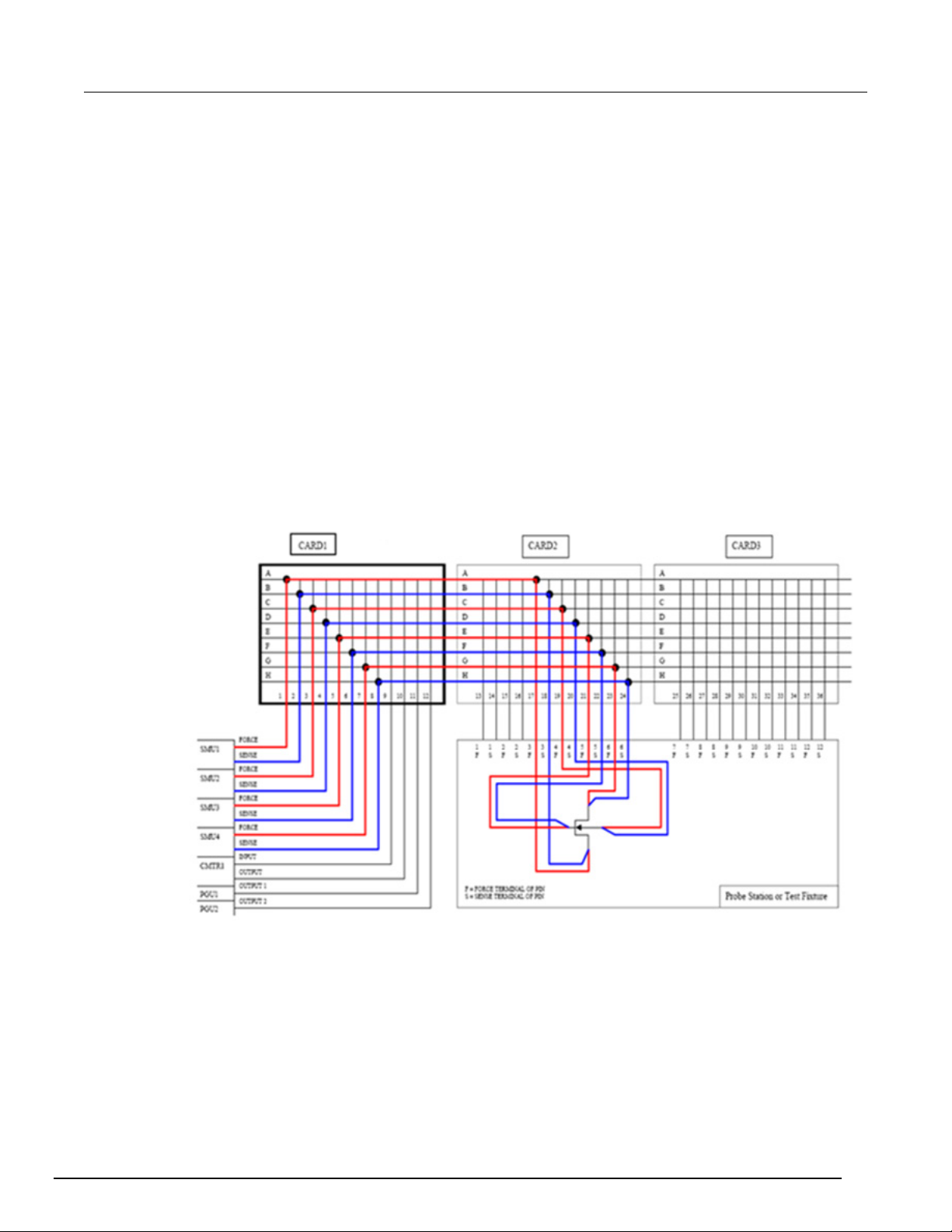
ACS Basic
ACS Basic hardware configuration
Automated Characterization Suite Reference Manual Section 4:
• Two-wire local sense: use this when the measurement-pathway resistance is small and the
associated voltage errors are negligible. The measurement pathway is comprised of the following
conductors, connected in series:
a. Cables used to connect the instruments to the matrix
b. Internal matrix-card signal path
c. Cables used to connect the matrix to the prober or test fixture
Current flowing through the measurement pathway creates a voltage drop (an error voltage) that is
directly proportional to the pathway resistance. This error voltage is present in all local sense voltage
measurements.
Four-wire remote sense can be used when sourcing and/or measuring voltage in a low-impedance
test circuit, and there can be errors associated with IR drops in the test leads. Voltage source and
measure accuracy are optimized by using four-wire remote sense connections. When sourcing
voltage, four-wire remote sensing ensures that the programmed voltage is delivered to the DUT.
When measuring voltage, only the voltage drop across the DUT is measured.
• Use four-wire remote sense for the following source-measure conditions
a. Sourcing and/or measuring voltage in low impedance (<1 kΩ) test circuits.
b. Enforce voltage compliance limit directly at the DUT
Figure 52: Instrument card, remote sense connection scheme example
ACSBASIC-901 Rev. E / August 2012 4-33
Page 68
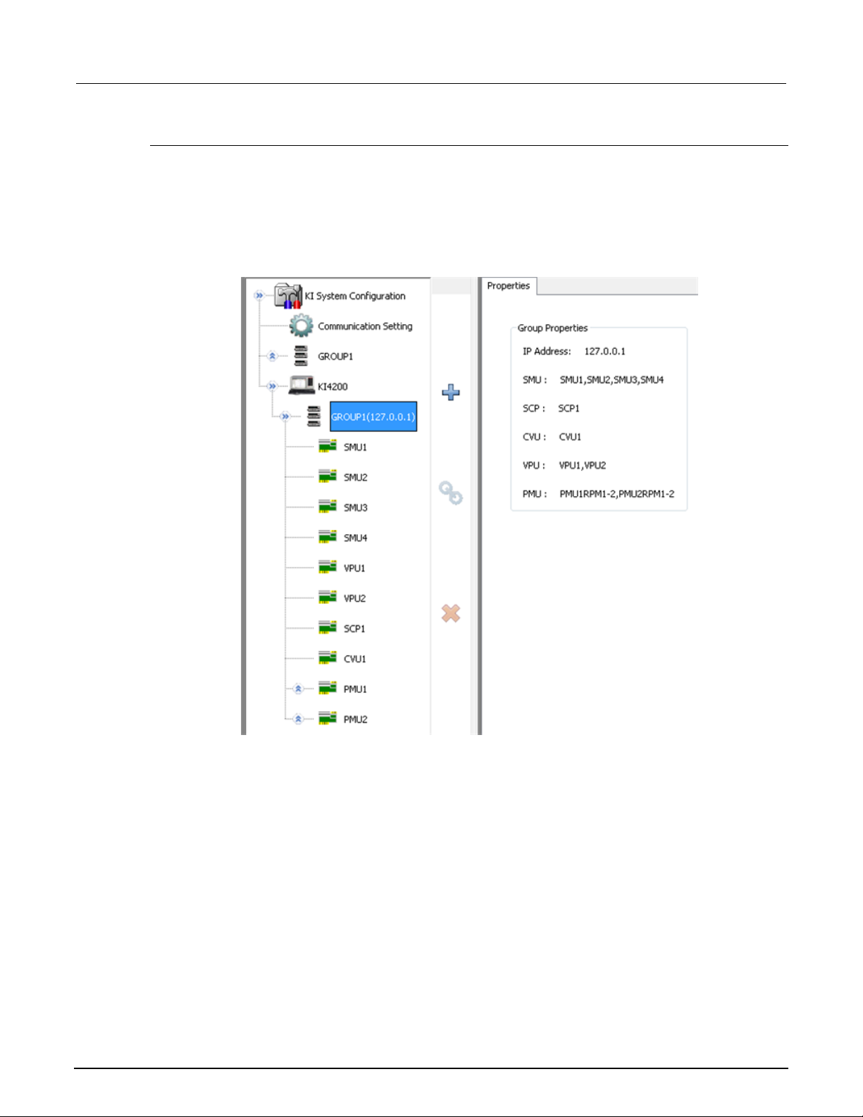
Section
Reference Manual
4: ACS Basic hardware configuration ACS Basic Automated Characterization Suite
Model 4200 system properties
When you select the KI 4200 node in the configuration navigator, the Model 4200-SCS system
properties are displayed in the work area (see next figure).
The work area shows the Model 4200 Group Properties, which contains the IP address, source
measure unit (SMU) name, scope (SCP) name, capacitance-voltage unit (CVU) name, voltage pulse
unit (VPU) name, and pulse measure unit (PMU) name.
Figure 53: Model 4200 group properties
4-34 ACSBASIC-901 Rev. E / August 2012
Page 69
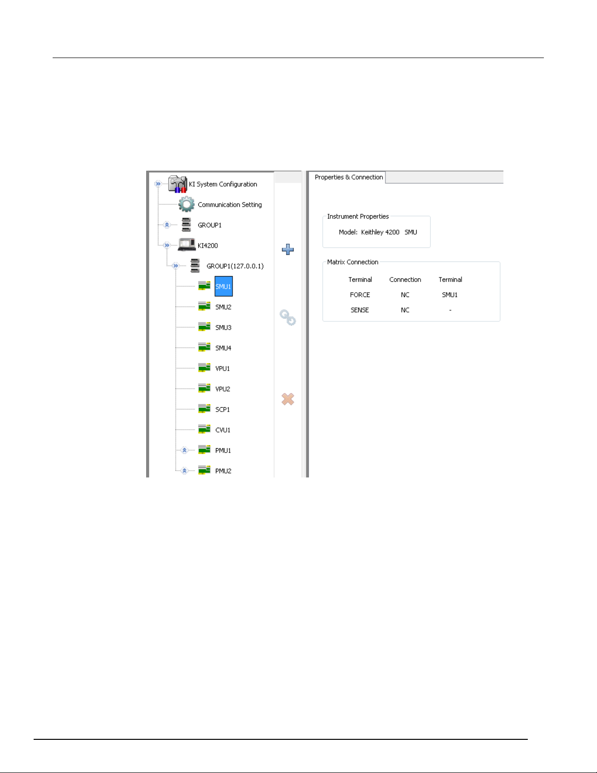
ACS Basic
ACS Basic hardware configuration
Automated Characterization Suite Reference Manual Section 4:
When you select the KI 4200 SMU node in the configuration navigator, the Model 4200-SCS SMU
system properties are displayed in the work area (see next figure).
The work area shows the Model 4200 SMU where you can see the Instrument Properties (the model
of the SMU). Additionally, you can see the Matrix Connection of the SMU that shows the Terminals,
Connection, Force, and Sense status.
Figure 54: Model 4200 SMU information
ACSBASIC-901 Rev. E / August 2012 4-35
Page 70
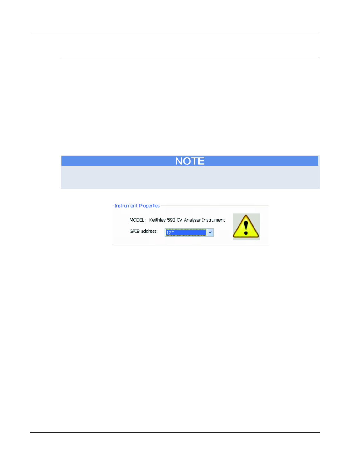
Section
Reference Manual
4: ACS Basic hardware configuration ACS Basic Automated Characterization Suite
Model 590 CV analyzer
When you select the Model 590 CV Analyzer in the configuration navigator, its Properties &
Connections tab opens in the work area.
The Properties & Connections tab provides access to the Model 590 instrument properties and useful
switch-matrix connection information. The Instrument Properties area of this Properties &
Connections tab provides access to the following Keithley Instruments Model 590 instrument
properties:
• Model: Full vendor name, model number, and instrument description.
• GPIB Address: you can use the drop-down arrow to select the address. Addresses that are in use
are displayed with asterisks (*) next to them. The minimum address value is 0; the maximum is
30 (GPIB address 31 is reserved as the Model 4200-SCS controller address). If the selected
GPIB address conflicts with the GPIB address of another instrument in the configuration, a
warning exclamation-point symbol (!) is displayed next to the address (see next figure).
You can programmatically read the GPIB address, and other instrument properties, on the system
configuration using the LPTLib getinstattr function. Proper usage of getinstattr allows you to
develop user libraries in a configuration independent manner.
Figure 55: GPIB address properties
When a matrix is included in the system configuration, the Matrix Connections area of this Properties
& Connections tab displays the matrix connections that are associated with the Model 590
measurement terminals.
4-36 ACSBASIC-901 Rev. E / August 2012
Page 71
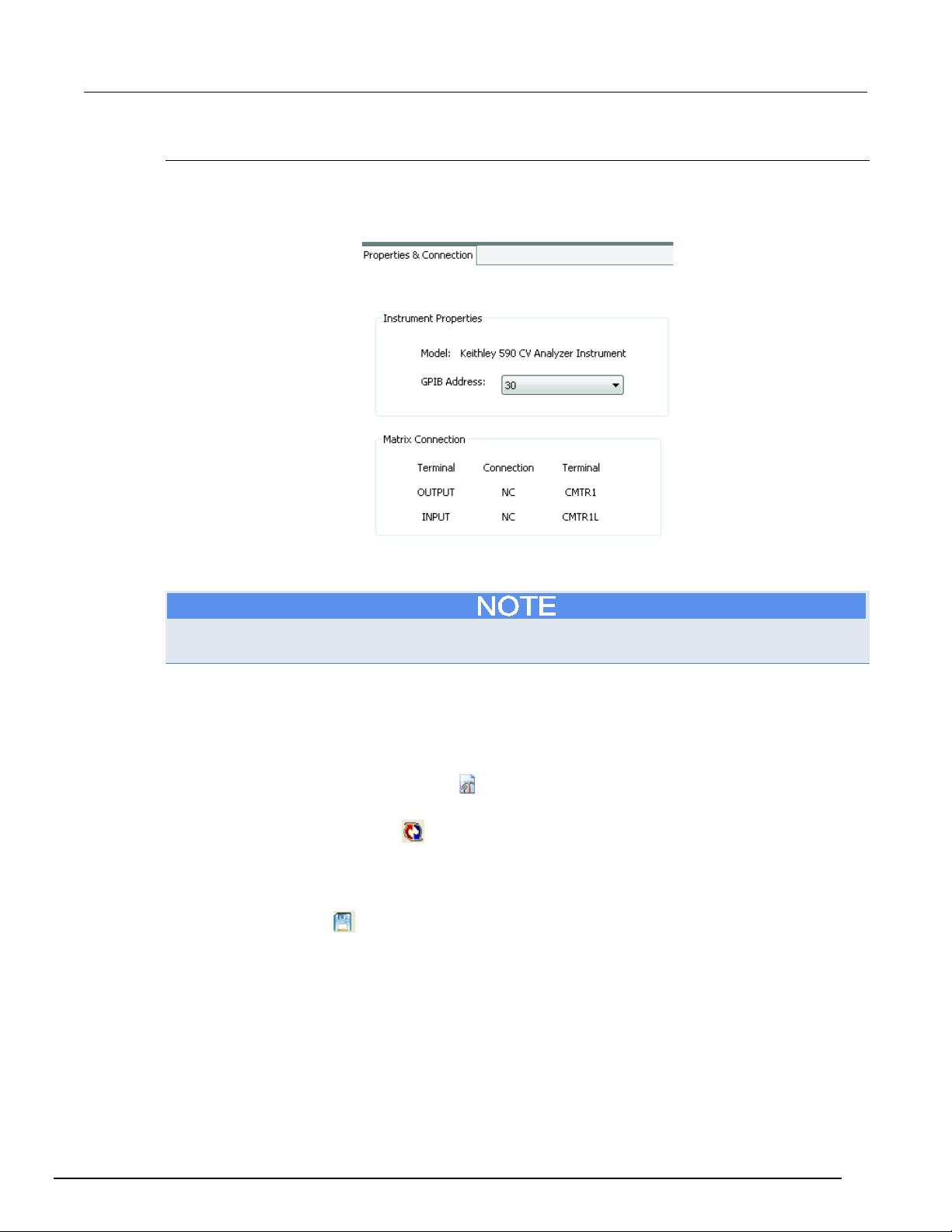
ACS Basic
ACS Basic hardware configuration
Automated Characterization Suite Reference Manual Section 4:
Capacitance meter configuration
When you configure a capacitance meter, the only item that you can change is the GPIB address.
You will also see the matrix connection displayed (see next figure).
Figure 56: Configuration of capacitance meter
Save the hardware configuration
You must close and restart ACS Basic after you make a change to the hardware configuration or the
new configuration will not be functional.
Check the hardware configuration
The hardware configuration utility is used to manage the hardware configuration. In order to check
your configuration, follow these steps:
1. Click the Hardware configuration icon
Tools menu of ACS Basic to start the hardware configuration (see next figure).
2. Click the Scan hardware icon
on the toolbar. The hardware information is displayed in the
work area.
3. Using the configuration navigator, navigate through the listed hardware. Verify that the hardware
information matches the configuration of the physical system.
4. Click the Save icon
to save the new configuration. Close and restart ACS Basic.
on the toolbar or choose Configure Hardware in the
ACSBASIC-901 Rev. E / August 2012 4-37
Page 72
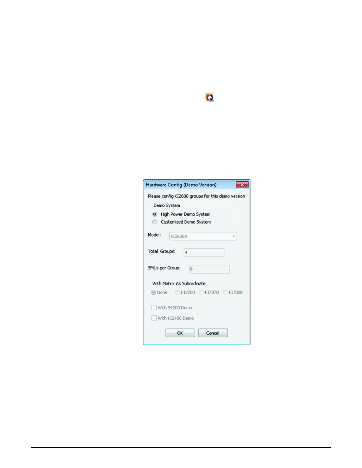
Section
Reference Manual
4: ACS Basic hardware configuration ACS Basic Automated Characterization Suite
Configure the hardware in demo mode
You can use the scan hardware function to set up a custom SMU configuration. If you run ACS Basic
in Demo mode, it can simulate a virtual system, such as including the Series 2600B, Series 2400,
Series 3700A, and Model 4200.
For example, when you click the Scan Hardware icon
, the hardware configuration dialog box
opens (see next figure). This is where you can choose a specific instrument model in the drop-down
list (for instance, KI2561A). Then you input the Total Groups and SMUs per Group information.
If you want a matrix (KI3700A, KI707B, or KI708B) in your configuration as a subordinate item, you
have three choices, otherwise you can choose None.
If you want to simulate a scan of the Model 4200-SCS, select the With S4200 Demo item.
If you want to simulate a scan of a Series 2400 instrument select the With KI2400 Demo item.
For external instruments, you can also add and remove as needed.
Figure 57: Hardware configuration in demo mode
Once you have completed your choices, click OK and the system configuration navigator is displayed
in the left pane, with corresponding information displayed in the work area.
4-38 ACSBASIC-901 Rev. E / August 2012
Page 73

Advanced operations .............................................................. 5-45
Section 5
ACS Basic test setup
In this section:
Test setup introduction ............................................................. 5-1
Single-test mode ...................................................................... 5-4
Multi-test mode ....................................................................... 5-10
Trace mode ............................................................................ 5-15
Data plot ................................................................................. 5-24
Test setup introduction
The ACS Basic interface consists of a variety of graphical user interfaces (GUIs) that allow you to do
the following:
• Create tests for one or more devices
• Build and edit test sequences
• View test results in tabular and graphical forms
• Analyze test results using built-in parameter extraction tools
Test modes
ACS Basic has three test modes:
1. Single-test mode
2. Multi-test mode
3. Trace mode
The Single-test mode is used to open and run a single test on a single device at a time.
In Multi-test mode, multiple test modules can be created on one or more devices and organized into a
single project. For example, Multi-test mode can perform multiple tests on a single device (target
application) or multiple tests on multiple devices (secondary use case). You can work with external
instruments (DMMs, switches, etc.) in Multi-test mode much easier than in any other mode.
Trace mode is for interactive operation with a source meter unit. You can adjust the maximum sweep
value and maximum power to the device. Also, you can easily transition between DC and pulse
forcing modes.
Page 74
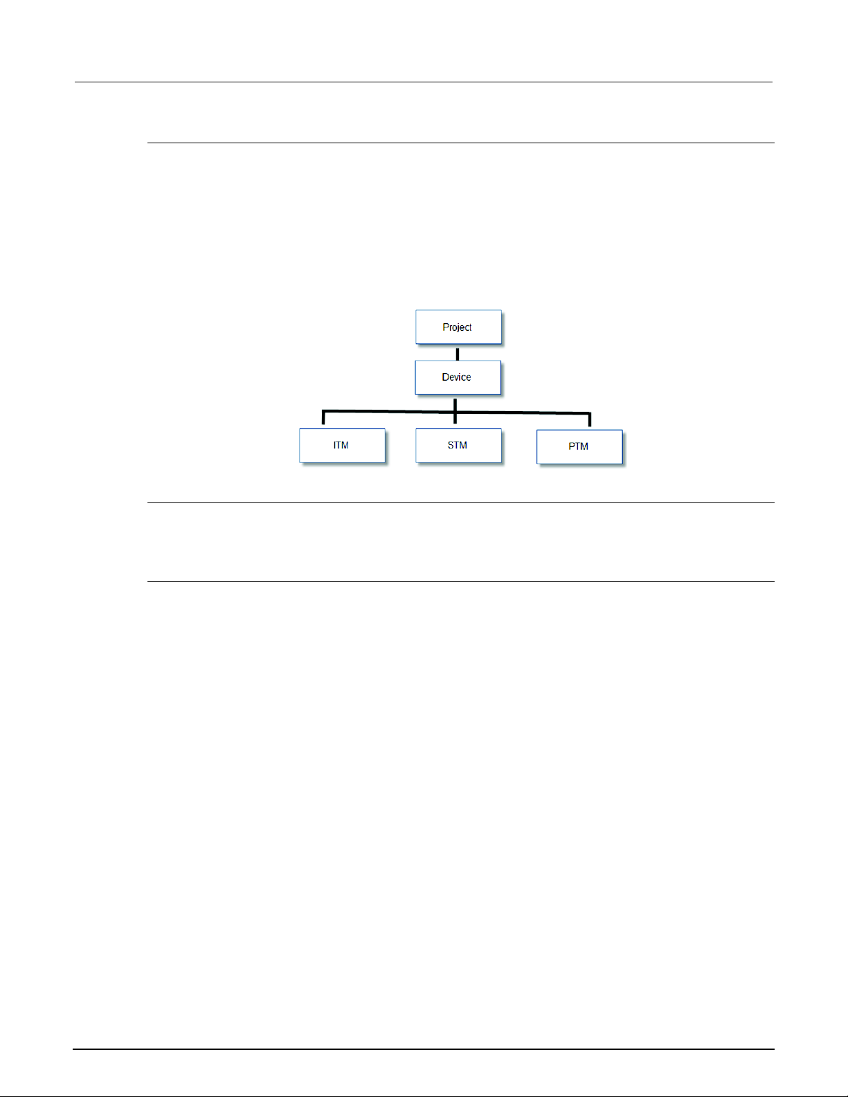
Section
e Manual
5: ACS Basic test setup ACS Basic Automated Characterization Suite Referenc
Test project
The test project defines and sequences all of the devices and specifies the tests to be performed on
each device. Projects are only valid for Multi-test mode.
Devices and their respective tests are organized within the configuration navigator, which appears in
the left panel of the ACS Basic interface. Use the configuration navigator to insert new test modules,
copy and paste existing test modules, and sequence the order in which tests are performed.
In Multi-test mode, the ACS Basic configuration navigator follows a logical hierarchy:
Figure 58: Multi-test mode hierarchy
Devices
Each project contains one or more devices to be characterized including transistors, diodes, resistors,
triacs, and capacitors.
Test modules
There are three types of test modules in ACS Basic:
1. Graphical interactive test module (ITM)
2. Script test module (STM)
3. Python language test module (PTM)
All three types of test modules have the same data sheet and data plot analysis functions. The
differences between ITMs, STMs, and PTMs include the following:
Graphical interactive test module (ITM)
An ITM allows you to define a test interactively using a graphical user interface (GUI). ITMs are
available for the Model 4200-SCS SMUs or Series 2600B System SourceMeter
®
instruments.
Script test module (STM)
An STM supports test script processor (TSP
™
) files. A TSP file is written for testing a device with a
Series 2600B System SourceMeter, Model 3706A System Switch/Multimeter, or Model 707B/708B
switch matrix in ICL mode. STM examples are installed with ACS Basic. These scripts can be
imported and modified in the STM workspace. STMs can be used with a user-created GUI in an XRC
format to create custom tests with a graphical interface.
5-2 ACSBASIC-901 Rev. E / August 2012
Page 75
ACS Basic
2600
PC/laptop or 4200
GPIB, TSP
Y+ Y Y
2600B
PC/laptop or 4200
GPIB, Ethernet,
TSP subordinate
Y+ Y Y
2651A &
2657A
PC/laptop or 4200
GPIB, Ethernet,
TSP subordinate
Y+ Y Y
4200
4200 only
GPIB
Y+
--
Y
3700A
PC/laptop or 4200
GPIB, Ethernet,
TSP subordinate
--
Y+
Y
instruments
Automated Characterization Suite Reference Manual Section 5: ACS Basic test setup
Python test module (PTM)
A PTM is a user-generated python script that can control instruments through a GPIB cable. You can
create an optional GUI to interface with the PTM in an XRC format, or in a customized GUI format.
PTM script examples are installed when ACS Basic is installed. These scripts can be imported and
modified in the PTM test module.
The following table indicates the instruments and communication interfaces supported with the
appropriate test modules (table legend: Y = supported, Y+ = recommended, -- = not supported).
Instrument
Series
2400 PC/laptop GPIB -- -- Y
Other external
ACS Basic installed on Communication
Interface
subordinate
PC/laptop or 4200 GPIB -- -- Y
ITM STM PTM
If you copy and paste a test module, the device settings will not carry over. It is necessary to reassign
the device settings if the test module is pasted in a different device. For example, if you copy an ITM
from a nMOSFET device and paste it in a npnBJT device, you will need to manually reassign the
device settings.
See Test Setup for more information on the types of test modules.
ACSBASIC-901 Rev. E / August 2012 5-3
Page 76
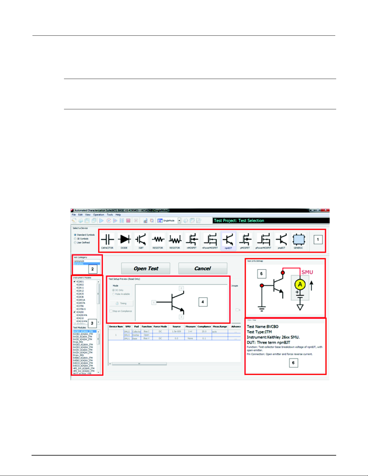
Section
Reference Manual
5: ACS Basic test setup ACS Basic Automated Characterization Suite
Single-test mode
Introduction
Single-test mode is used for importing and running one test module on one device at a time. The
single test can be an ITM, STM, or PTM.
Test selection GUI
The test selection GUI of the Single-test mode is shown in the next figure and includes the following
sections:
1. Select a Device - select a device view (Standard, 3D Symbols, or User Defined).
2. Test Category - click on the desired device and the selected icon will highlight.
3. Instrument and Test Modules - select the test instrument model. The test modules applicable
for this instrument are listed in the Test Modules area. If two or more instruments are selected,
the Test Modules are will display all of the modules available to any of the selected instruments.
4. Test Setup Preview - is a visual presentation of the type of test.
5. Test Info Bitmap - this is an image of the type of test selected.
6. Test Help - displays detailed specific information about the test.
Figure 59: Single-test mode test selection GUI
5-4 ACSBASIC-901 Rev. E / August 2012
Page 77

ACS Basic
Automated Characterization Suite Reference Manual Section 5: ACS Basic test setup
Select a test module in single-test mode
1. Select a device view (Standard, 3D Symbols, or User Defined).
• Standard Symbols uses electrical symbol images.
• 3D Symbols uses three-dimensional images of electrical symbols.
• User Defined items are created using the Graphically Define a New Device dialog box. For more
information on how to create a user defined device, refer to the Graphically define a new device topic.
2. Click on the desired device and the selected icon will highlight.
3. All test categories belonging to this device are listed in the Test Category area. Select your
desired category:
• CommonLib: The common library for test devices, including some tests that are for specific instruments,
such as the CV_4200CVU test for the Model 42xx CVU, SWITCH_Control for the Models 707/708
matrix, KI37XX_DMM_R_2Wire for the Model 37xx, among others.
• Parametric: Test libraries for device parametric tests. When you select a device, and select the
instruments in the Instrument Models area, the Test Modules area will list all of the parametric tests
available for the device. These test modules use specific SMUs for device parametric tests, such as,
IdVd, IdVg test for MOSFET, among others.
• WLR_script: The wafer level reliability tests for selected devices, such as the HCI (Hot Carrier Injection)
nMOSFET device.
Not all devices have a test library in all three test categories.
4. Select the test instrument model. The test modules applicable for this instrument are listed in the
Test Modules area. If two or more instruments are selected the Test Modules area will display all
of the modules available to any of the selected instruments.
5. Select a test module.
6. The test information preview is displayed on the right panel. This information includes Test Setup
Preview, Test Information Bitmap, and Test Help.
ACSBASIC-901 Rev. E / August 2012 5-5
Page 78
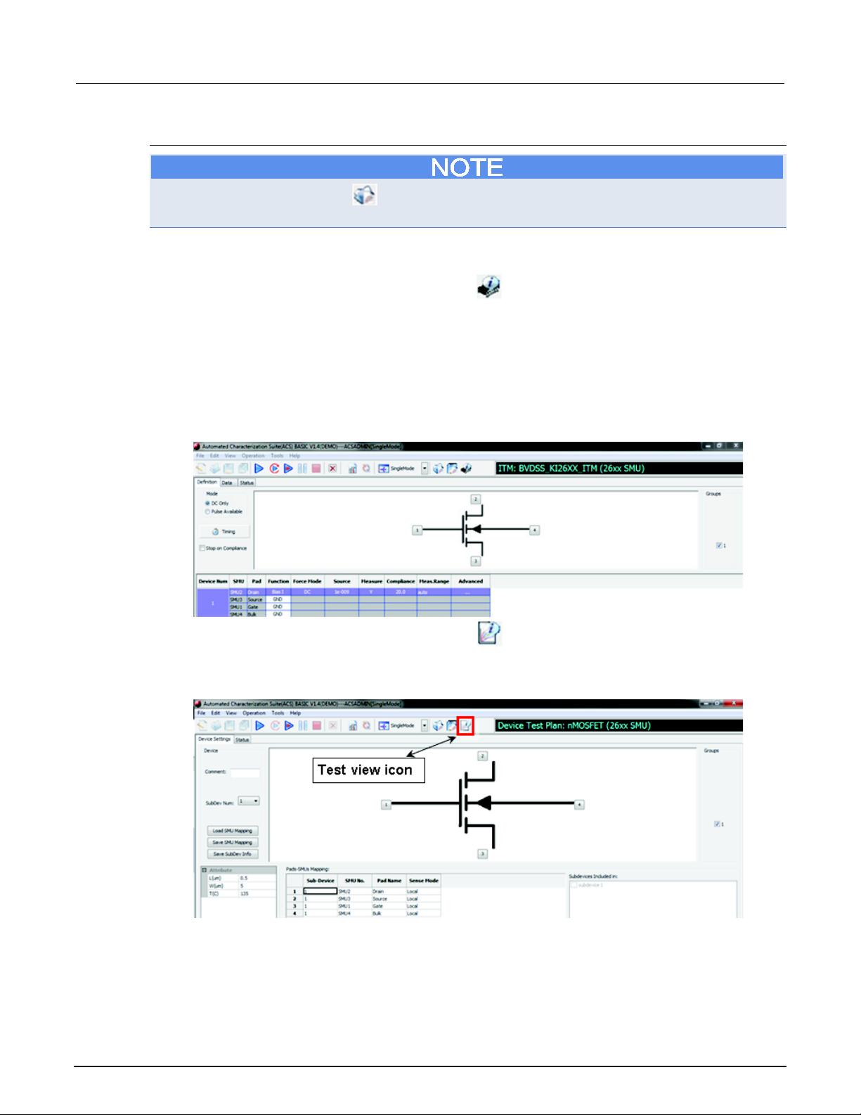
Section
Reference Manual
5: ACS Basic test setup ACS Basic Automated Characterization Suite
Open and edit the test module
Click the Return to library icon at any time to terminate the open test process and return to the
previous test.
1. Click the Open Test button to open the test view GUI. In this GUI, you can modify the test
module settings and run the test module.
2. In the test view GUI, click the Device view icon
to open the device view GUI (see next
figure). Use Device View to designate the test and measurement instruments that are connected
to each device terminal.
To configure an ITM, refer to Configure a graphical interactive test module (ITM).
To configure an STM, refer to Configure a script test module (STM).
To configure a PTM, refer to Configure a python test module (PTM).
Figure 60: Test view GUI
1. In the device view GUI, click the Test view icon to return to the test view GUI (see next
figure).
Figure 61: Device view GUI
5-6 ACSBASIC-901 Rev. E / August 2012
Page 79
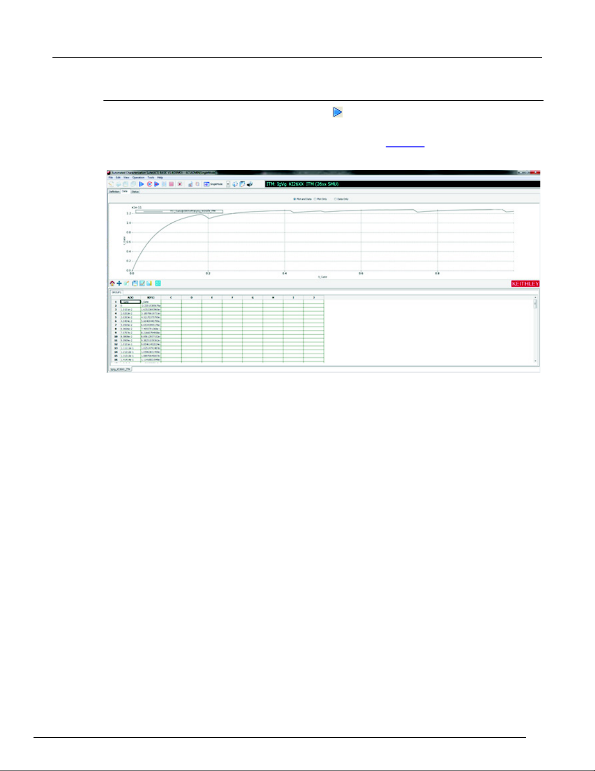
ACS Basic
Automated Characterization Suite Reference Manual Section 5: ACS Basic test setup
Run the test module
Once the test setup is completed, click the Run icon . For more information on running the test
module, refer to Run individual tests.
The test results appear in the Data tab (see next figure). Refer to Data plot
for details on the Data tab.
Figure 62: Test Data tab
ACSBASIC-901 Rev. E / August 2012 5-7
Page 80
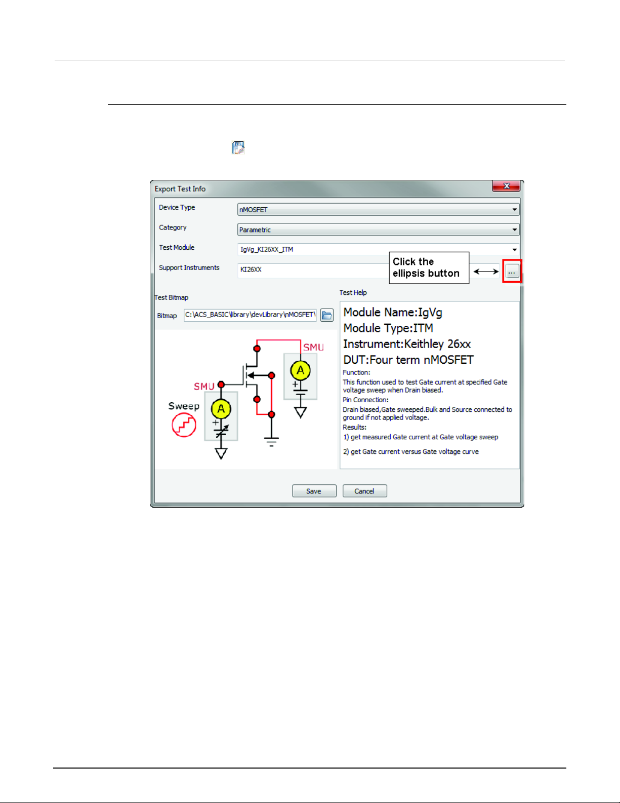
Section
Reference Manual
5: ACS Basic test setup ACS Basic Automated Characterization Suite
Save the test module to the library
The test module can be saved to the device library for future use. The saved information includes
both test settings and test results.
Click the Export Test icon
on the toolbar; the save test information GUI opens (see next figure).
Figure 63: Save Test Info dialog box
5-8 ACSBASIC-901 Rev. E / August 2012
Page 81
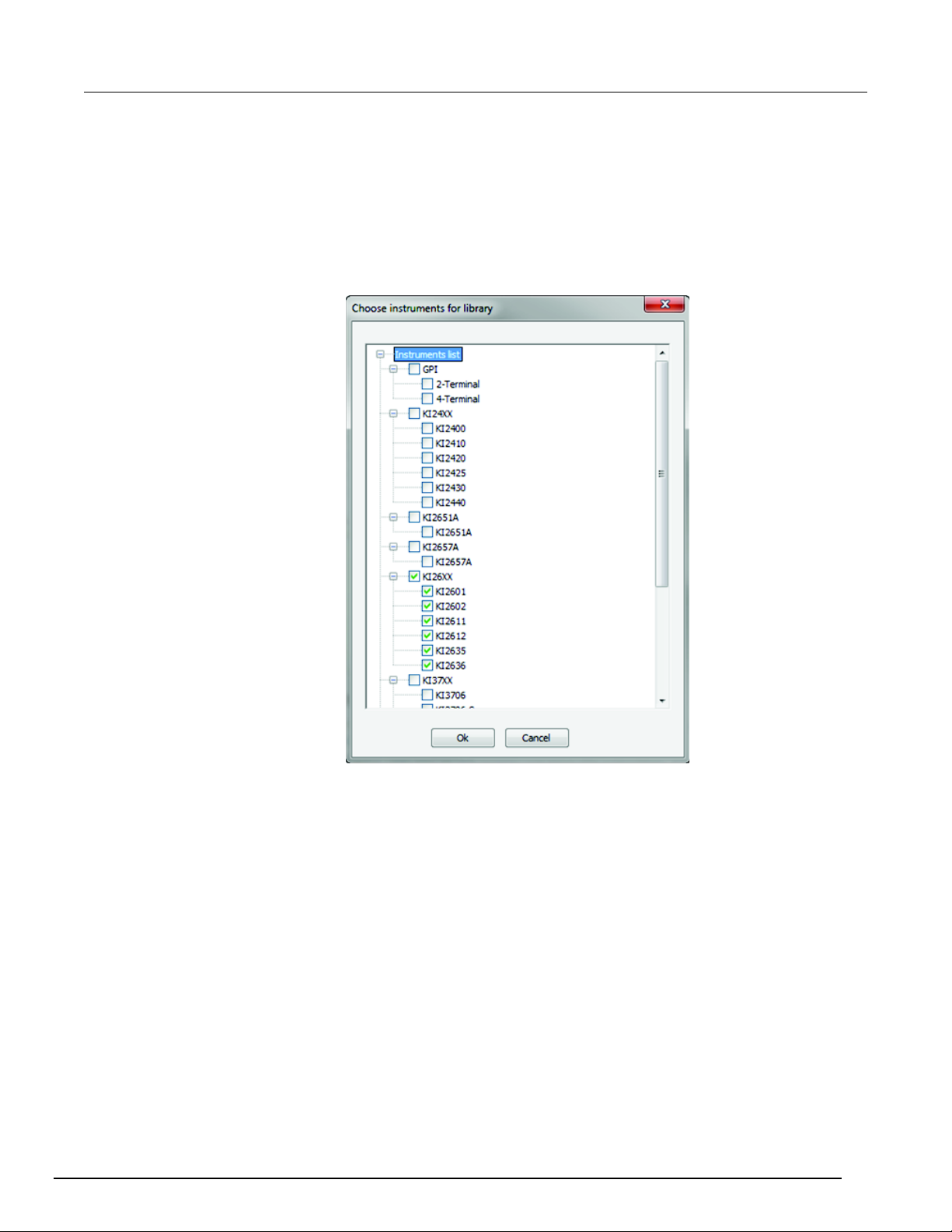
ACS Basic
Automated Characterization Suite Reference Manual Section 5: ACS Basic test setup
a. Select a device type for the module in the Device Type drop-down list.
b. Select a test category in the Category list.
c. Input a test name in the Test Module edit box. Note that the new Test Module name should be
different from the existing name to avoid overwriting the original module.
d. Click the ellipsis button (see previous figure) of the Support Instruments edit box. In the pop-up
dialog box choose your desired instruments for the library by clicking the box next to the
instrument (see next figure). Click OK.
Figure 64: Save selected instruments for testing
e. If desired, change the test bitmap by clicking on the folder icon to find a new bitmap.
f. If desired, change the description by entering the text in the right editing panel.
Click OK to save the test module to the test library. After the test module is saved, ACS Basic returns
to the Open Test GUI where the previous test can be opened and used again.
ACSBASIC-901 Rev. E / August 2012 5-9
Page 82
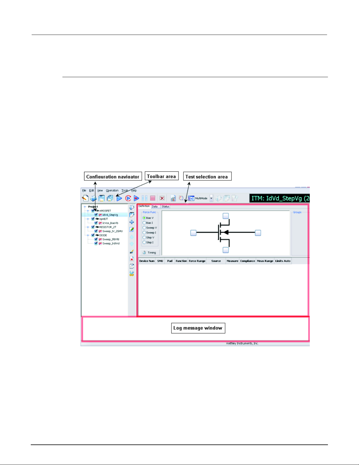
Section
Reference Manual
5: ACS Basic test setup ACS Basic Automated Characterization Suite
Multi-test mode
Introduction
Multi-test mode uses a project to organize devices and tests. The configuration navigator (see next
figure) has the following logical hierarchy:
• Project
• Device 1
• Test module 1 (ITM, STM, or PTM)
• Test module 2 (ITM, STM, or PTM)
• Device 2
• Test module 1 (ITM, STM, or PTM)
• Test module 2 (ITM, STM, or PTM)
Figure 65: Multi-test mode GUI
5-10 ACSBASIC-901 Rev. E / August 2012
Page 83
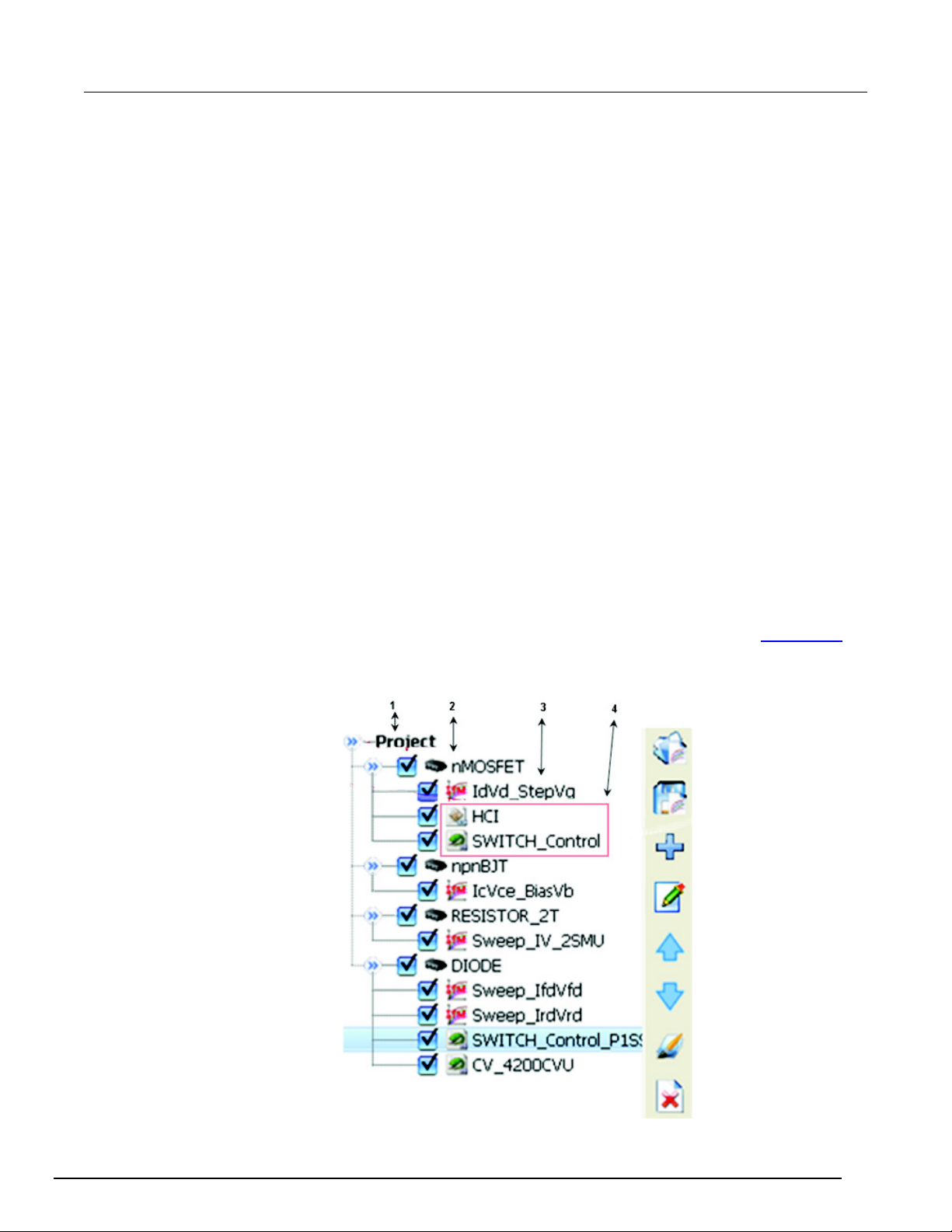
ACS Basic
Automated Characterization Suite Reference Manual Section 5: ACS Basic test setup
The configuration navigator is the primary interface for building, editing, and viewing a project plan,
and for specifying and accessing each project plan component.
When you select a navigator component (test or device) you can do the following:
• Add a new component
• Delete an existing component
• Run the tests associated with this component
Clicking on a navigator component opens the configuration interface on the right panel that includes
settings, test results, and status information.
The next figure displays the typical project plan components that are displayed in the configuration
navigator. The following explanation of the numbered items correspond to the numbers in the the next
figure:
1. Project Plan: Defines and sequences all devices tested, and all tests/operations to be performed
at each. It typically corresponds to one die on a wafer.
2. Device Plan: Defines and sequences all tests for a specific device, including transistors, diodes,
and resistors.
3. ITM: Completely defines a parametric test without programming, using a series of easily
configured graphical user interfaces which show data numerically and graphically in real time.
Provides for the display of both raw data and analyzed data.
4. STM/PTM: Defines an operation; an external instrument operation, using a TSP or PTM user
module. These test modules are connected to the STM and are configured with user-supplied
parameter values (several STMs may be associated with the with the same user module).
Configuration is done using a supplied library or may be created by the user with Script Editor's
simple graphical user interface.
For details about building a project plan using the configuration navigator, refer to the Project plan
topic.
Figure 66: Configuration navigator
ACSBASIC-901 Rev. E / August 2012 5-11
Page 84
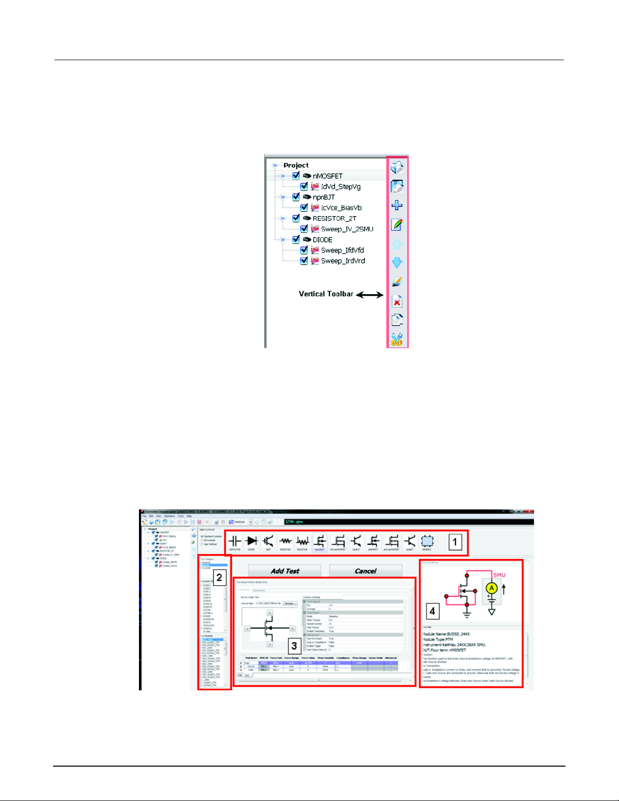
Section
Reference Manual
5: ACS Basic test setup ACS Basic Automated Characterization Suite
Vertical toolbar
The vertical toolbar is only accessible in Multi-test mode. See the next figure for the location in the
Multi-test mode GUI:
Figure 67: Vertical toolbar location
Multi-test mode GUI
When ACS Basic is opened in Multi-test mode, you will see the configuration navigator and the work
area that shows the settings, test results, and status information.
The test selection GUI of the Multi-test mode is shown in the next figure. Note that there are four main
sections:
1. Select a Device
2. Test Category - select a test module
3. Test Setup Preview
4. Test Information
Figure 68: Multi-test mode work area
5-12 ACSBASIC-901 Rev. E / August 2012
Page 85

ACS Basic
setup
Automated Characterization Suite Reference Manual Section 5: ACS Basic test
Build a project plan
Create a new project:
1. Click the New icon
on the toolbar (or you can click New in the File menu). The New Test
Project dialog box opens.
2. Enter the following information:
• Template: Use to load an existing project template. Enter the storage folder name or use the Browse
function to find the location. This field may be left blank.
• Project Name: Enter the new project name (this is required).
• Project Directory: Select a directory where you want to save the project, or use the default directory.
Use the Browse function to find a location.
• Technology: Optional device information.
• Product: Optional device information.
3. Click OK to complete the new test project.
When you open ACS Basic and a test project, the project directory path displays in the title bar of the
ACS Basic GUI. All project information is saved to this directory.
Add a test module to the project (see Select a test module in single-test mode
for more details):
1. Select a device view (Standard, 3D Symbols, or User Defined).
2. Click on the desired device and the selected icon will highlight.
3. All test categories belonging to this device are listed in the Test Category area. Select your
desired category.
4. Select the test instrument model. The test modules applicable to this instrument are listed in the
Test Modules area. If two or more instruments are selected the Test Modules area will display all
of the modules available to any of the selected instruments.
5. Select a test module.
6. The test information preview is displayed on the right panel. This information includes Test Setup
Preview, Test Information Bitmap, and Test Help.
7. Click the Add Test function to add the test module to the configuration navigator.
If the test module imported belongs to the same kind of device, as an existing device in the
configuration navigator, the module will be added to the existing device automatically.
If the imported test module does not belong to the same kind of device, a new device node will be
added to the configuration navigator.
Configure the test module:
After the test module is added, click the device in the configuration navigator to view and edit test
details.
ACSBASIC-901 Rev. E / August 2012 5-13
Page 86
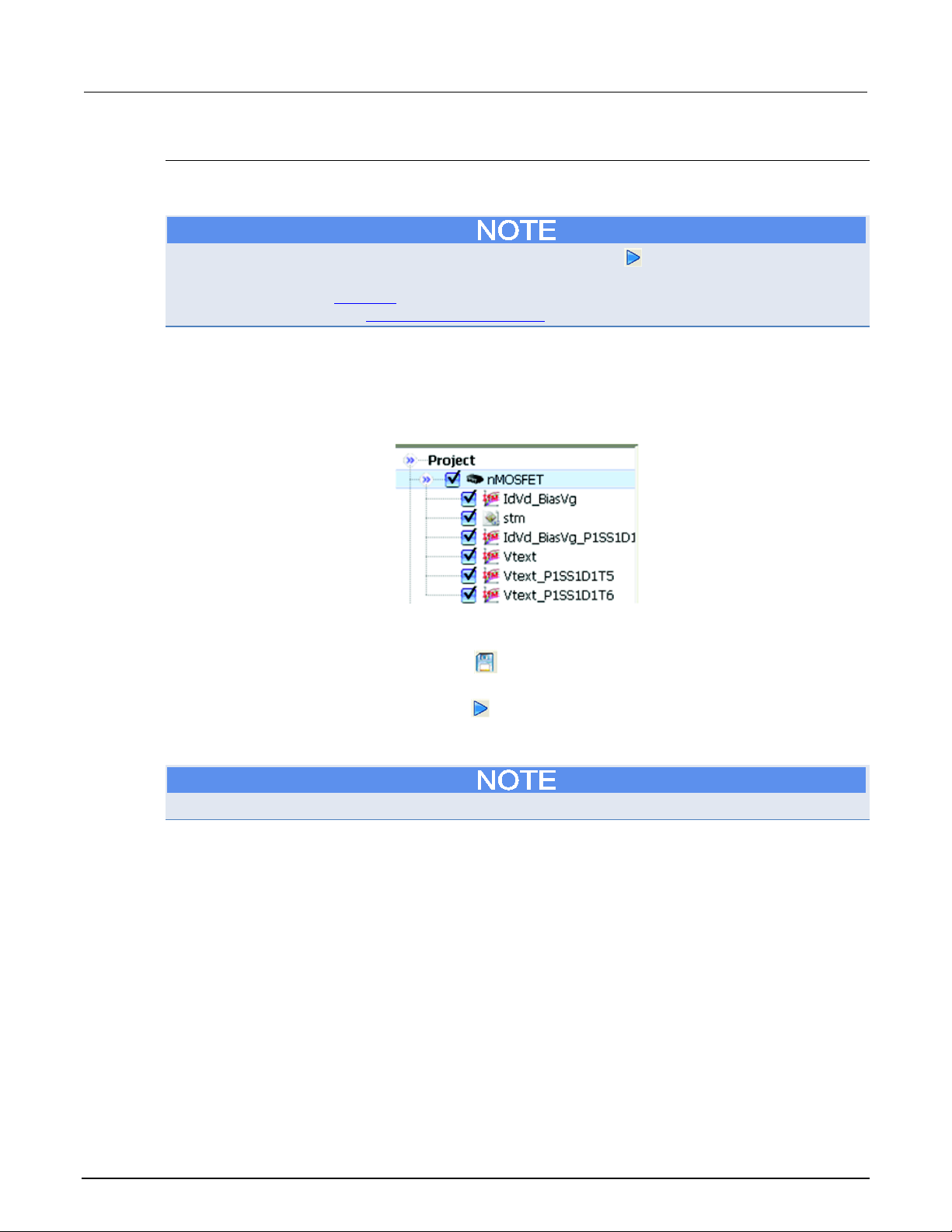
Section
Reference Manual
5: ACS Basic test setup ACS Basic Automated Characterization Suite
Execute individual device plans
After a test plan has been built, you can execute individual parts of a project plan at the test module
level, the device level, or the project level.
Each time you execute a test or test sequence using the Run icon , the data from each test is
inserted to its own Data worksheet. Each new run updates this worksheet (for more information on
worksheets, refer to the Data plot topic. You can also generate appended worksheets for tests and
test sequences. Refer to the Append and clear append topic.
You can execute an individual Device Plan with the selected components, ITMs, PTMs, ans STMs,
assigned to it in the order that they appear in the configuration navigator. In the configuration
navigator, select the box corresponding to the device to run. For example, in the next figure, the
nMOSFET has been selected.
Figure 69: Select the device to run
1. Enable the tests assigned to this device by checking the box next to the test name; or disable a
test by un-checking the box.
2. To save the plan, click on the Save icon
in the ACS Basic toolbar, or select the Save function
in the ACS Basic File menu.
3. Start execution by clicking the Run icon
in the toolbar. The Run toolbar icon turns gray while
the test executes, and the Abort Test/Plan icon illuminates for the duration of the test. The test
sequences will run one at a time.
Selecting only an individual ITM, STM, or PTM on the test tree will run only that specific test.
5-14 ACSBASIC-901 Rev. E / August 2012
Page 87
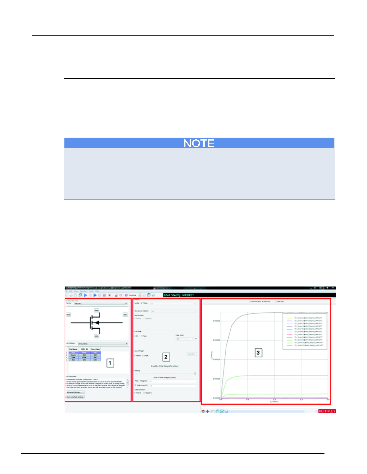
ACS Basic
Automated Characterization Suite Reference Manual Section 5: ACS Basic test setup
Trace mode
Introduction
Trace mode provides interactive control of SMU instruments to achieve real-time performance. Only
Series 2600B instruments (Models 2601B/2602B, 2611B/2612B, 2635B/2636B), Series 2650A
(Models 2651A, 2657A) and Series 2400 instruments (Models 2400, 2401, 2410, 2420, 2425, 2440)
are supported. ACS Basic can perform DC and pulse tests on Series 2600B, and 2650A instruments
in Trace-mode, but it can only perform DC measurements on Series 2400 instruments.
Trace-mode allows you to quickly and easily setup the instrument for fast, visual results and save the
data for later comparison or analysis
Trace-mode only supports the Series 2400, Series 2600B, and the Models 2651A/2657A. However,
you cannot connect a Series 2400 and a Series 2600B instrument to the same device. If you are
using a Series 2400 on one device terminal, you must use a Series 2400 instrument on the other
device terminal(s). However, you can use a Series 2600B and a Model 2651A instrument in any
combination. Also, Trace-mode only supports the SCPI protocol for Series 2400 SMUs. For Series
2600B, it only supports the GPIB communication mode to the master and does not support LXI
communication to the master.
Test GUI
Select TraceMode after clicking the drop-down arrow from the operation toolbar at the top of the ACS
Basic GUI. The Trace-mode GUI is shown in the next figure.
The GUI includes:
1. Device setting: used to map the SMU, select the test module, and set the advanced settings.
2. Test setting: used to set the test information when the test module is enabled.
3. Trace Test Data: used to show the test result.
Figure 70: Trace-mode test GUI
ACSBASIC-901 Rev. E / August 2012 5-15
Page 88
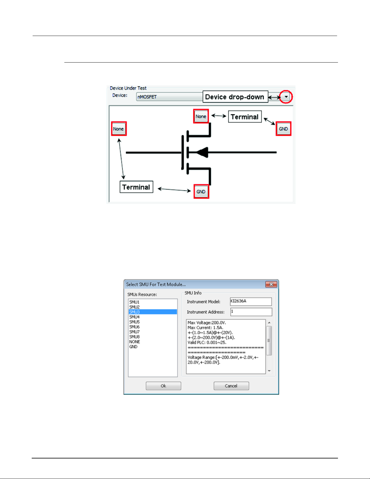
Section
Reference Manual
5: ACS Basic test setup ACS Basic Automated Characterization Suite
Open a test module in Trace mode
1. Select a device in the Device drop-down list (in the Device Under Test area)(see next figure).
Figure 71: Device Under Test area
2. Select a test module for the device. All test modules belonging to this device are listed in the Test
Modules drop-down list.
3. Connect an SMU to the desired device terminals.
a. Click the button next to the device terminal and the Select SMU For Test Module dialog box
opens (see next figure).
b. Select a desired SMU resource for the terminal in the SMUs Resource box. The SMU Info box
indicates the Instrument Model and Instrument Address.
c. Click OK to complete the SMU setting.
Figure 72: Select SMU For Test Module
5-16 ACSBASIC-901 Rev. E / August 2012
Page 89
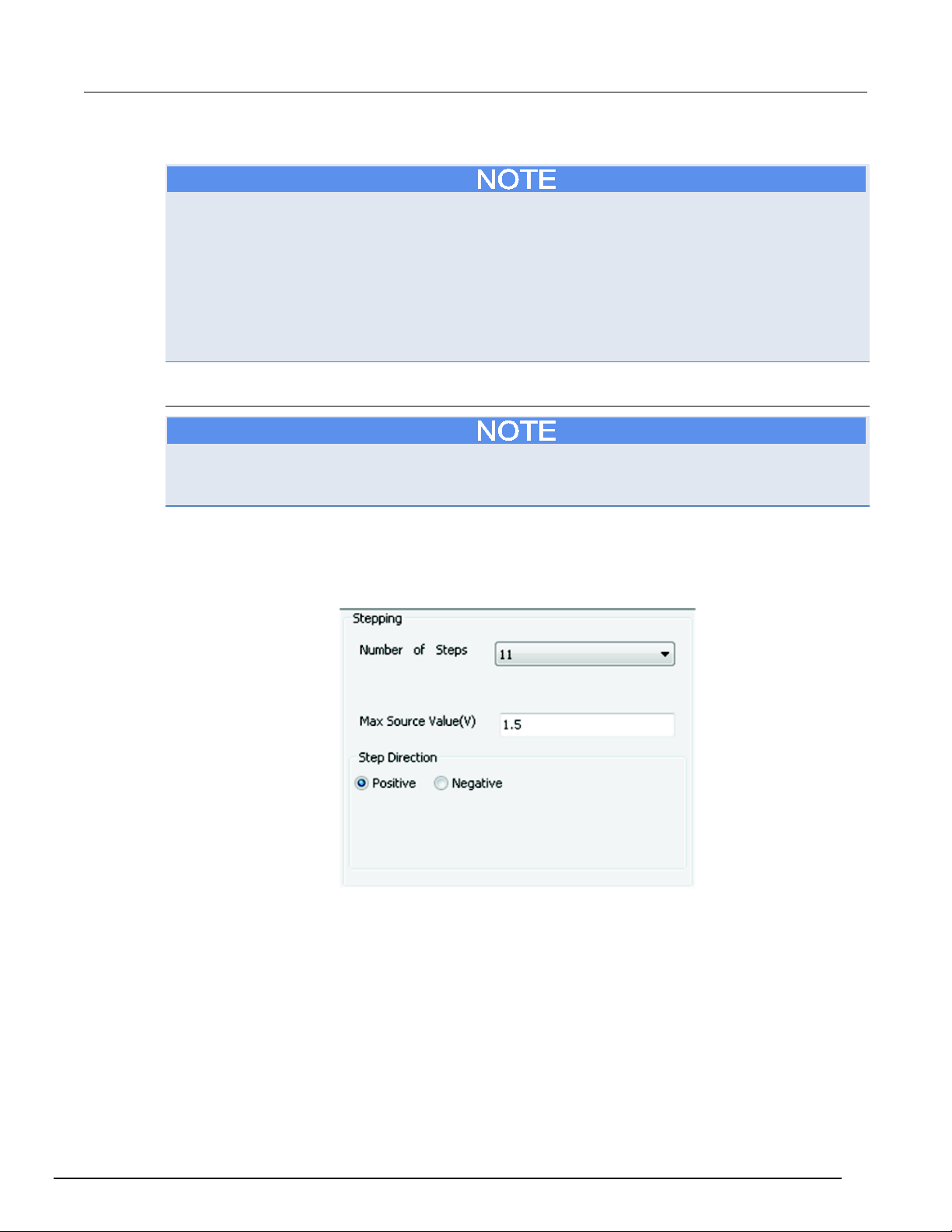
ACS Basic
Automated Characterization Suite Reference Manual Section 5: ACS Basic test setup
Series 2400 instruments can only be used with other Series 2400 instruments connected to the same
device. Also, Series 2600B instruments can only be used with other Series 2600B or Model 2651A
and 2657A instruments connected to the same device. Additionally, when a Model 2651A or 2657A is
connected to the drain of a MOsFET or collector of a BJT or IGBT, the Series 2600B cannot be
connected to the Source terminal or Emitter terminal. These terminals must be connected to GND.
This is to prevent damaging the Series 2600B SMUs with high current from the Model 2651A or
damaging the 2657A with high current from the Series 2600B. Also, if there is more than one group of
Series 2600B SMUs in the system, only the SMUs in group one will appear in the SMU Resource
box.
Configure Trace mode
ACS Basic has default settings for Trace mode. You can change the settings as needed. If you
decide to use the default settings, you can click the Return to Default Settings function which is
found under the Test Description.
Step setting
See the next figure for an example of the Stepping variables.
Figure 73: Stepping variables
ACSBASIC-901 Rev. E / August 2012 5-17
Page 90
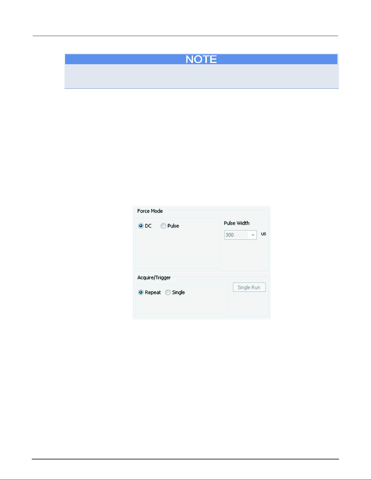
Section
Reference Manual
5: ACS Basic test setup ACS Basic Automated Characterization Suite
Not all test modules have the step test. Only tests that include Step V or Step I as a force function
have the "Stepping" panel enabled. The default setting is determined if the current test type is sweep,
on the Collector or Drain terminal, and step, on the Base or Gate terminal.
• Number of steps: for testing the step voltage measurements. Valid from 1 to 11. If the input is 1,
the step terminal will be applied a constant bias at the Max Source Value.
• Max Source Value: is the stop amplitude value of the step; it’s always positive. If the test is step
V, the units are in volts; if it’s step I, the units are in amps.
• Step Direction: indicates the direction in which the source value of the Step SMU changes.
When set to positive, the step test executes from 0 to maximum; when negative, from 0 to
negative maximum.
For more information on step and sweep definitions, refer to the Configure an SMU's
Bias/Sweep/Step table topic.
Force Mode (for sweeping SMU)
See next figure for an example of possible Force Mode functions.
Figure 74: Force setting box
5-18 ACSBASIC-901 Rev. E / August 2012
Page 91
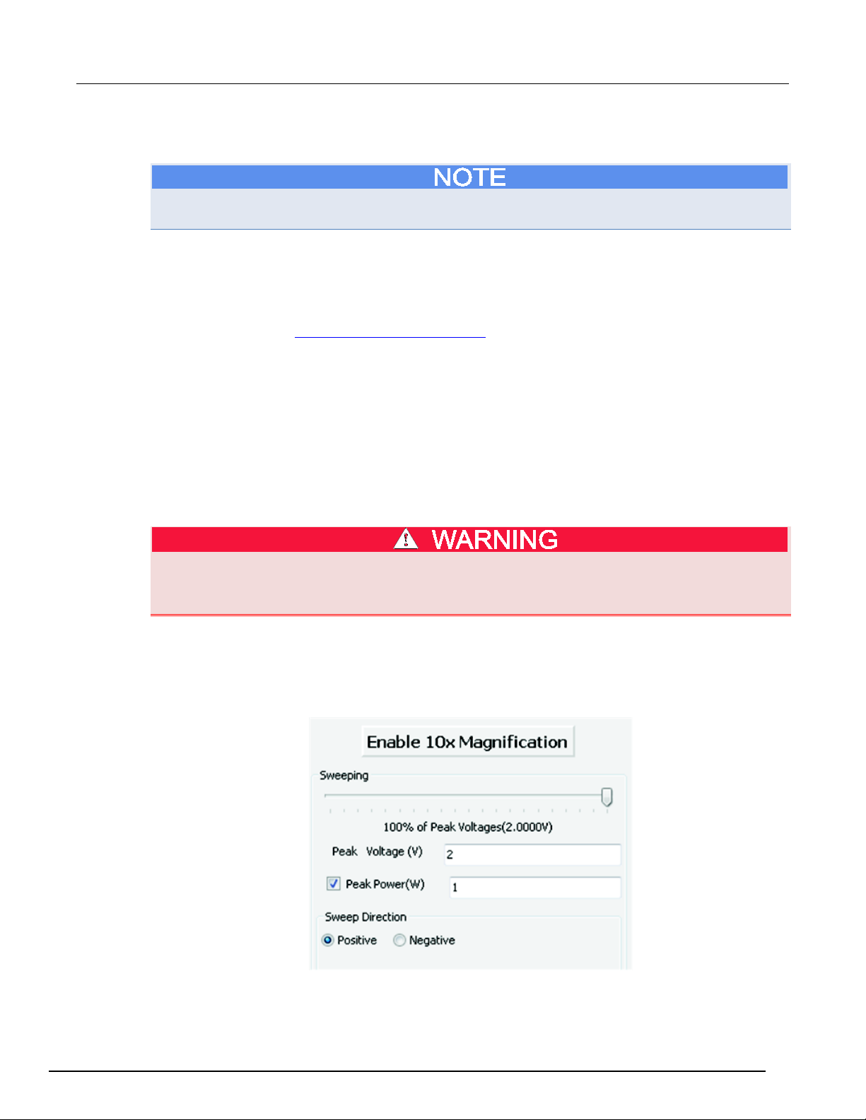
ACS Basic
Automated Characterization Suite Reference Manual Section 5: ACS Basic test setup
• DC/Pulse: is applied to both the stepping and sweeping SMUs. If pulse mode is selected, the
Pulse Width input box will be enabled.
If the sweeping SMU is a Series 2400, only DC mode can be applied. For a combined 2651A SMU,
only Pulse mode can be applied.
• Pulse width: The width of the pulse in pulse mode. The units are microsecond.
• Acquire/Trigger mode: Select Single to perform the test once. Select Repeat to perform the test
until Stop is selected. When Single is selected the Single Start button is enabled.
Pulse period defaults to the maximum allowable value. You can adjust the duty cycle in the Advanced
Settings GUI. Refer to Advanced Setting Preferences
For the Series 2600B SMU (non-2651A), the maximum pulse width is 1000µs.
For the 2651A SMU, if current is in the 10A to 50A range, and voltage is in the 10V to 40V range, the
maximum pulse width is 300µs. Otherwise, the maximum pulse width is 1000µs.
For the 2651A SMU 100A/80V combined SMU, if voltage is higher than 10V, the maximum pulse
width is 300µs. Otherwise, the maximum pulse width is 1000µs.
Pulse mode cannot be used on Series 2400 SMUs in Trace mode.
for more information.
In Single Trigger mode, the SMU output remains on after each test at zero volts. If you want
to change connections or insert a new device, first click Stop. When the test has stopped,
the SMU output is disabled.
Sweep control setting
The next figure shows the Sweeping control settings.
Figure 75: Sweep variables
ACSBASIC-901 Rev. E / August 2012 5-19
Page 92
Section
Reference Manual
5: ACS Basic test setup ACS Basic Automated Characterization Suite
• Enable 10X Magnification: allows you to toggle between enable or disable and is only available
during testing. When enabled, the step value will decrease by 10 times, and the function will
change to "Disable 10x Magnification." You can disable by selecting the function again.
Sweeping setting
• Sweep slider: controls the actual final value of the sweeping SMU. The slider position is a
percentage of the Peak Value. There are always 21 points in the sweep. For example, sliding the
sweep slider is similar to turning the knob on a curve tracer. Sliding the slider to the right
increases the maximum value while sliding to the left decreases the maximum value. The sweep
slider can be controlled in the following ways:
• Use your mouse to drag the slider. It has a resolution of 1% of the Peak Value.
• Use your mouse wheel to control the slider. Move the wheel down moves the slider to the left, and
move the wheel up moves the slider to the right. It has a resolution of 0.5% of the Peak Value.
• Use the left and right arrow keys on your keyboard to control the slider. It has a resolution of 0.1% of the
Peak Value.
• Use the up and down arrow keys on your keyboard to control the slider. It has a resolution of 1% of the
Peak Value.
• Peak Voltage: is the absolute maximum stop value for the sweeping SMU. The actual stop value
depends on the current position of slider. The units are volts.
• Peak Power: sets the maximum power output at any point of the sweep. Current compliance is
calculated at each point of the sweep by peak power/programmed voltage level.
Power compliance only affects the SMU designated as the sweeping SMU. For instance, in the
IdVg_StepVd test, the SMU assigned to the gate is the sweeping SMU. Therefore, power compliance
limits the maximum power to the gate terminal of the FET, not the drain terminal.
5-20 ACSBASIC-901 Rev. E / August 2012
Page 93
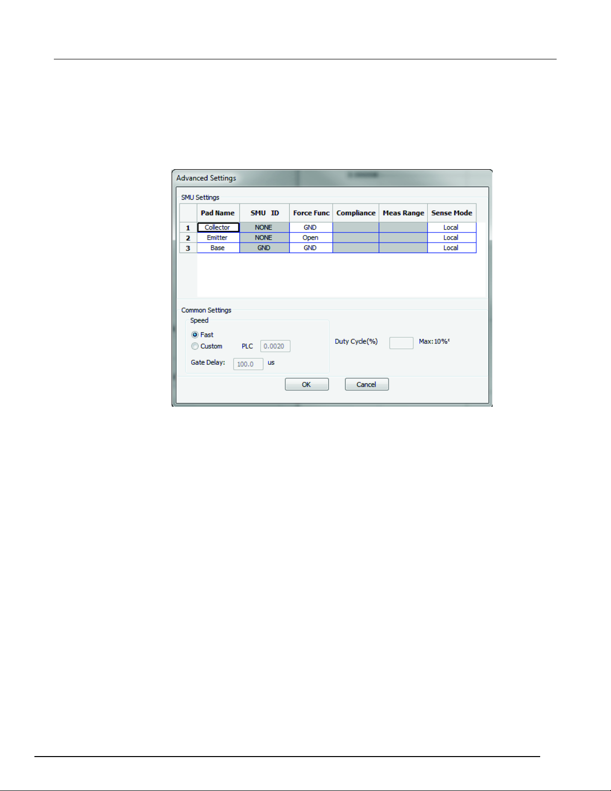
ACS Basic
Automated Characterization Suite Reference Manual Section 5: ACS Basic test setup
Advanced Settings
The Advanced Settings can be used to change the measure range, number of power line cycles
(NPLC), and other settings
Click the Advanced Settings function and a dialog box opens (see next figure).
Figure 76: Advanced Settings dialog box
ACSBASIC-901 Rev. E / August 2012 5-21
Page 94
Section
Reference Manual
5: ACS Basic test setup ACS Basic Automated Characterization Suite
There are several settings that you can adjust:
• Pad Name: can be edited here, but will be disabled in the test setup GUI.
You will get a Warning message if you change a pad name. The warning states that changing the pad
name will cause a Pad/SMU mismatch of all related test modules in the library.
• SMU ID: is disabled here. It can only be assigned in the device map field in the test setup GUI.
• Force Func: allows you to select SweepV/StepV/StepI/GND/Open from a drop-down list. This
column will be disabled in the test setup GUI.
• Compliance: sets the compliance value for a given SMU. The value is limited by the
specifications of the SMU. Note that this specification is not the same in Pulse and DC mode. If
the compliance value is only valid in Pulse mode, you will be unable to select DC as the Force
Mode.
• Meas Range: will match the force function if the measure function matches the force function.
The measurement range also affects the Force Mode. If the measurement range selected is only
valid in Pulse mode, then DC will be disabled in the Force Mode field. If a measurement is not
assigned to the corresponding pad, the Meas Range cell is disabled.
Current measurement ranges in Trace mode may be restricted based upon the SMU to ensure a fast
and interactive response in Trace mode. Should more sensitive measurement ranges be required,
use Single-test Mode or Multi-test Mode. For example, for the Model 2636A, the minimum settable
range is 100nA. Therefore, the 10nA, 1nA and 100pA ranges will not be accessible in Trace mode.
• Speed: sets the measurement NPLC to Fast or Custom. For Series 2600B SMUs, fast speed is
defined as 0.002PLC, for Series 2400 SMUs, it is defined as 0.01. Refer to the The Speed area to
learn more about the speed area in the common settings.
A custom PLC should be limited according to the SMU’s specifications. When you setup a custom
PLC, the pulse width in the test setup GUI should be larger than 2*PLC/local frequency.
To achieve fast speeds, a PLC value less than 0.1 is recommended.
• Gate Delay: sets the delay time after gate bias has been applied. This setting will ensure that the
gate bias is applied before the drain voltage or current bias. When the Force Mode is Pulse and
the test device is a MOSFET or IGBT, the pulse period and the gate pulse width will increase by
the amount specified in the input value. If the value is set to a value larger than 50% of the pulse
width, then the Gate delay will be set to 50% of the pulse width.
• Sense Mode: sets the sense mode of the SMU to either Local or Remote. The test modules for
IGBTs are all set to remote sense to guarantee measurement accuracy which is required in high
current tests.
• Duty Cycle: displays the maximum allowable duty cycle and the currently selected duty cycle. By
default, the duty cycle is set to the maximum possible. Adjust this value to reduce the duty cycle.
5-22 ACSBASIC-901 Rev. E / August 2012
Page 95
ACS Basic
Model 2651A SMU
20A
40V
10%
50A
20V
10%
Model 2651As combined in
100A
18V
10%
36V
1%
Model 2651As combined in series
45A
20V
10%
80V
1%
Automated Characterization Suite Reference Manual Section 5: ACS Basic test setup
Maximum current Maximum voltage Maximum duty cycle
50A 40V 1%
parallel
For Series 2600B SMU (non-2651A), the maximum duty cycle is adjusted by the current compliance
or max source value. If the current value applied for tests requires more than 0.1 A, the max value is
limited at 1%.
After configuring the Advanced Settings, click OK.
The Advanced Settings items are the same as in an ITMs in Single or Multi-test mode. For more
information on how to set the Force Func, Compliance, Meas Range, and other items in the
Advanced Settings, refer to the Configure an SMU's Bias/Sweep/Step table topic.
Run the test module
After the test is configured, click the Run icon .
The trace mode test will run repeatedly or once by clicking Single Run (for details about repeat and
single testing, refer to the Force Mode
The test result (plot and data) are displayed in real time in the Test Data area. If testing is set to
Repeat, the test data is refreshed repeatedly to show the latest test result. If testing is set to Single,
the sweeping test will run when you click the Run icon
Data area. Each time you click the Run icon
Data area.
topic).
and the test result is displayed in the Test
, the test will run and the results will display in the Test
When the trace mode test is running, you can use the sweep slider to adjust the stop value of the
sweep in real time. When you adjust the slider to a certain percentage, such as 60% of the peak
value (for example 10V), the next time sweep will run from start to 60% of 10V through 6V which will
become the stop value. And the Test Data area will immediately show the results of new sweeping
test. Click the Stop icon
to end the trace mode test.
Save a test module to the library
The test modules for Trace mode can be saved to the device library. The saved information includes
both test settings and test results.
1. Click the Save Test icon
• Note that the new Test Module name should be different from the existing name to avoid overwriting the
original module.
2. Click OK. All your changes will be saved to the library.
3. After the test module is saved, ACS Basic returns to the Open Test GUI.
on the toolbar; the save test information dialog box opens.
ACSBASIC-901 Rev. E / August 2012 5-23
Page 96
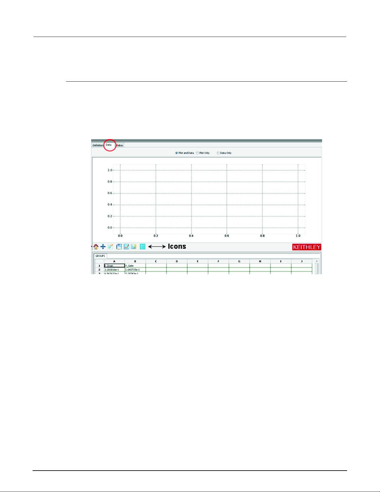
Section
Reference Manual
5: ACS Basic test setup ACS Basic Automated Characterization Suite
Data plot
Open a graph sheet
The Graph sheet is integrated with the Data sheet. There are two ways to open a Graph sheet:
Option 1: When setting up an ITM, STM, or PTM, you can switch to the Graph sheet of the current
test by clicking the Data tab. Results of the current test are displayed, and graphs can be drawn
according to the results. The next figure shows a graph sheet of a test with a data sheet at the
bottom.
Figure 77: Un-configured graph sheet of a test
5-24 ACSBASIC-901 Rev. E / August 2012
Page 97
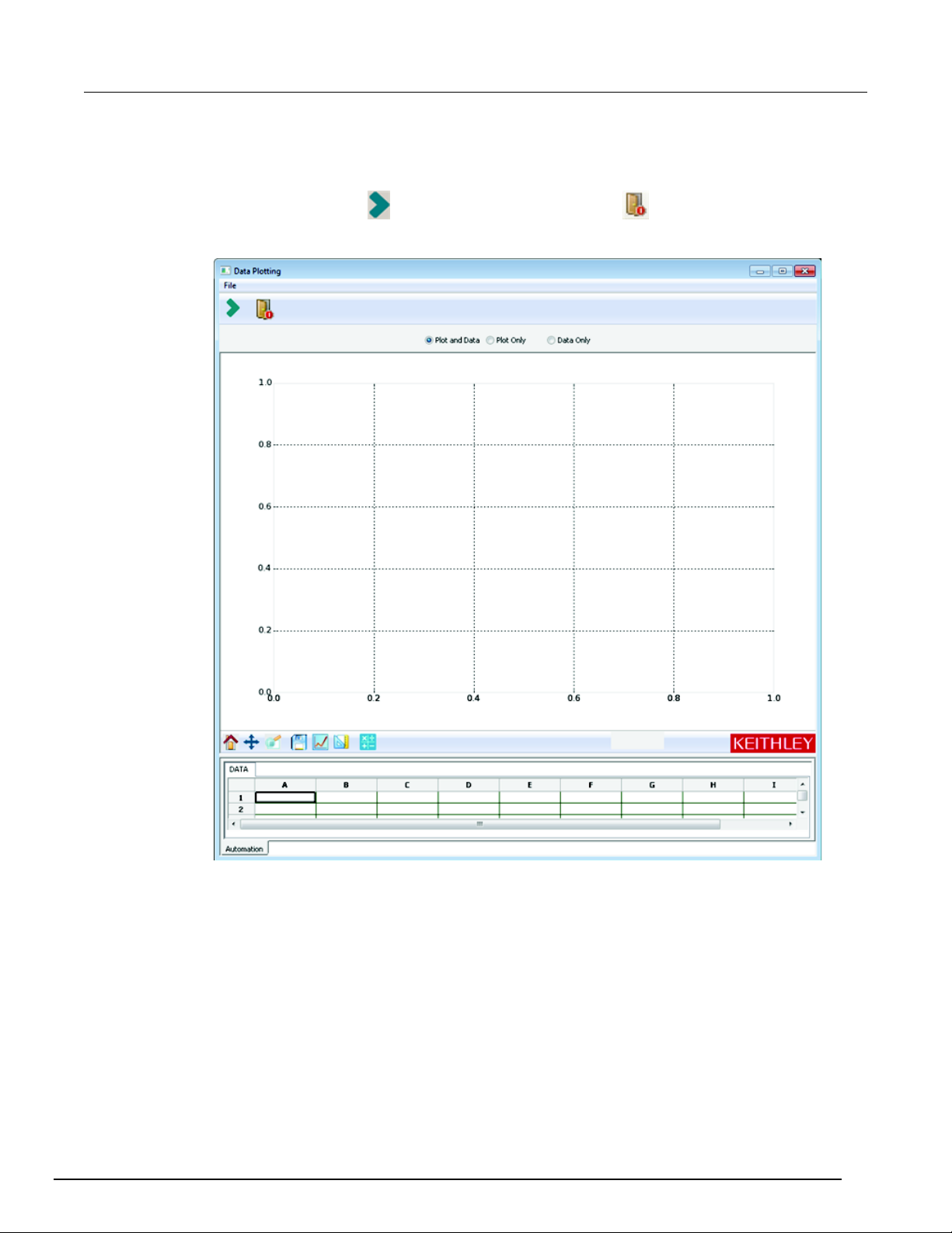
ACS Basic
Automated Characterization Suite Reference Manual Section 5: ACS Basic test setup
Option 2: Click Tools on the menu bar, then choose Offline Data Plotting and the Data plotting tool
dialog box will open (see next figure). Select a blank Data Plotting sheet similar to the one shown in
the previous figure. Data and graphs on this sheet are not limited to the current test or the current
project. Click the import icon
to import data. Click the exit icon to exit the page.
Figure 78: Data plotting tool
ACSBASIC-901 Rev. E / August 2012 5-25
Page 98
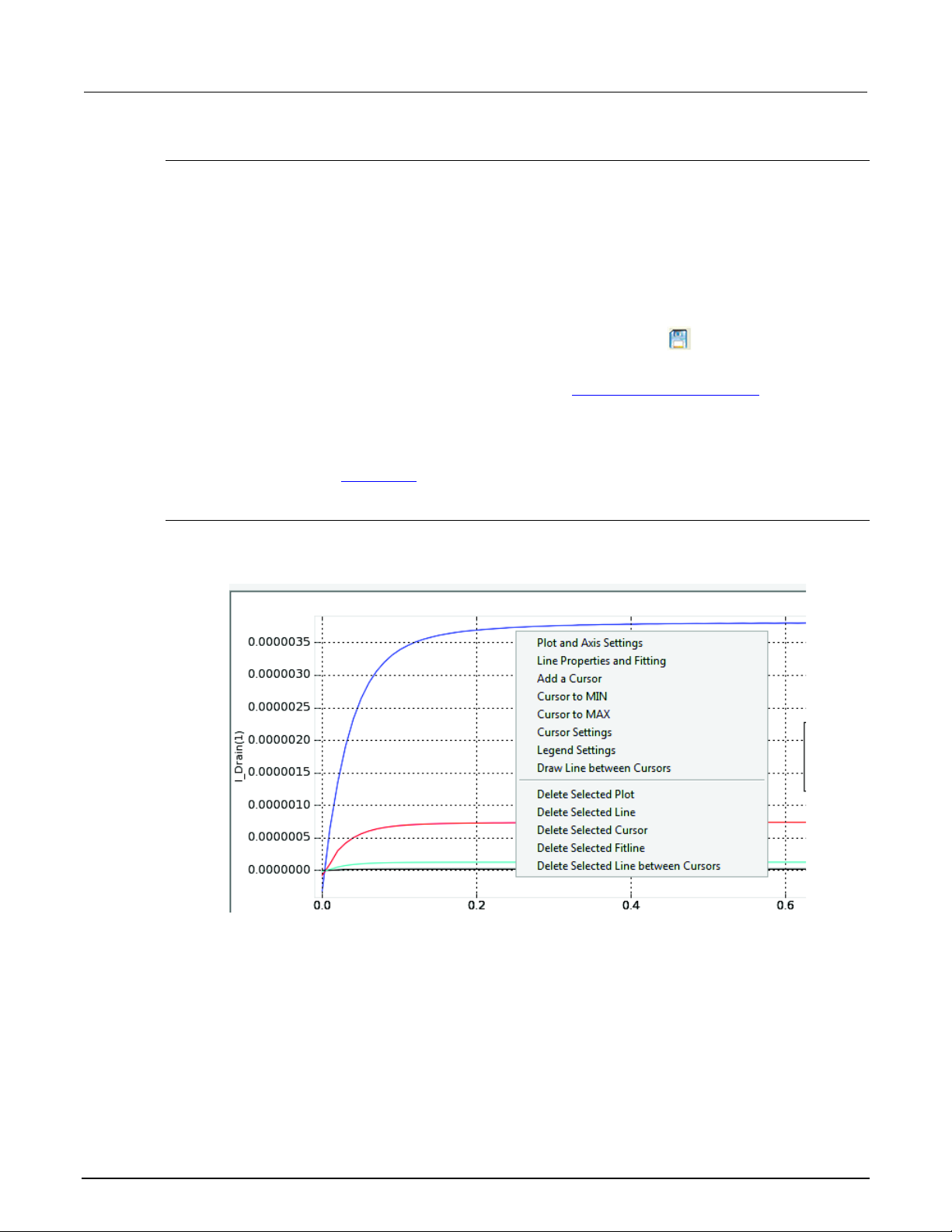
Section
Reference Manual
5: ACS Basic test setup ACS Basic Automated Characterization Suite
Control the properties of the graph
Items in the Graph Settings menu and the Graph toolbar control the properties of the graph.
Toolbar icons
The toolbar is located between the graph section and the data section and contains seven icons:
• Home: is used to return the graph to its original size (after zoom).
• Pan: permits panning of the graph.
• Zoom: enlarges a small, selected part of the graph.
• Save: saves the plot as a separate graphics file. Click the Save icon to display the Save to
file dialog box. You can save the plot as a .png, .ps, .eps, .csv, or .svg format.
• Plot: creates a graph out of the data selected (see the Define a graph and plotting topic for more
information).
• Plot Auto Scale: auto scales all the graphs on the graph sheet.
• Formular: performs data calculations on test data, as well as on the results of other Formulator
calculations (see the Formulator
topic for more information).
Access the graph settings menu
To view the Graph Settings menu, right-click on any portion of the graph (see next figure).
Figure 79: Graph settings menu
5-26 ACSBASIC-901 Rev. E / August 2012
Page 99

ACS Basic
Automated Characterization Suite Reference Manual Section 5: ACS Basic test setup
The Graph Settings Menu functions are summarized below:
Plot and Axis Settings: sets general properties of the selected graph and the parameters of the axis.
Many sub-functions are provided. For more information, refer to the Define a graph and plotting
topic.
Line Properties and Fitting: sets the properties of a selected line and makes the fitting if the cursors
are set. For more information, refer to the Define a graph and plotting
topic.
Add a Cursor: adds a floating cursor to the location where you have your mouse pointer.
Cursor to MIN: moves the selected cursor to the minimum point of the attached curves.
Cursor to MAX: moves the selected cursor to the maximum point of the attached curves.
Cursor Settings: adds a cursor to a graph and sets the cursor properties. For more information, refer
to the Define a graph and plotting
topic.
Draw Line between Cursors: draws a linear line between two selected cursors.
Delete Selected Plot: deletes the plot below where the menu is displayed from the graph sheet.
Also, all other plots will get resized.
Delete Selected Line: deletes a selected line from the plot. To delete a specific line, right-click the
line and choose Delete Selected Line from the menu.
Delete Selected Cursor: deletes the selected cursor. To delete a cursor, right-click the cursor and
choose Delete Selected Cursor in the menu.
Delete Selected Fitline: deletes the selected fitline cursor. To delete a fitline, right-click the fitline and
choose the Delete Selected Fitline in the menu.
Delete Selected Line between Cursors: deletes the selected line between the two cursors. To
delete a line between cursors, right-click the line and choose the Delete Selected Line between
Cursors in the menu.
Define a graph and plotting
There are two steps to define a graph and plot the data:
1. Define the data to be graphed.
2. Plot the data.
Define the data to be graphed
There are two steps to define and graph data:
1. Assign the data to an axis.
2. Assign the axis to a plot.
ACSBASIC-901 Rev. E / August 2012 5-27
Page 100
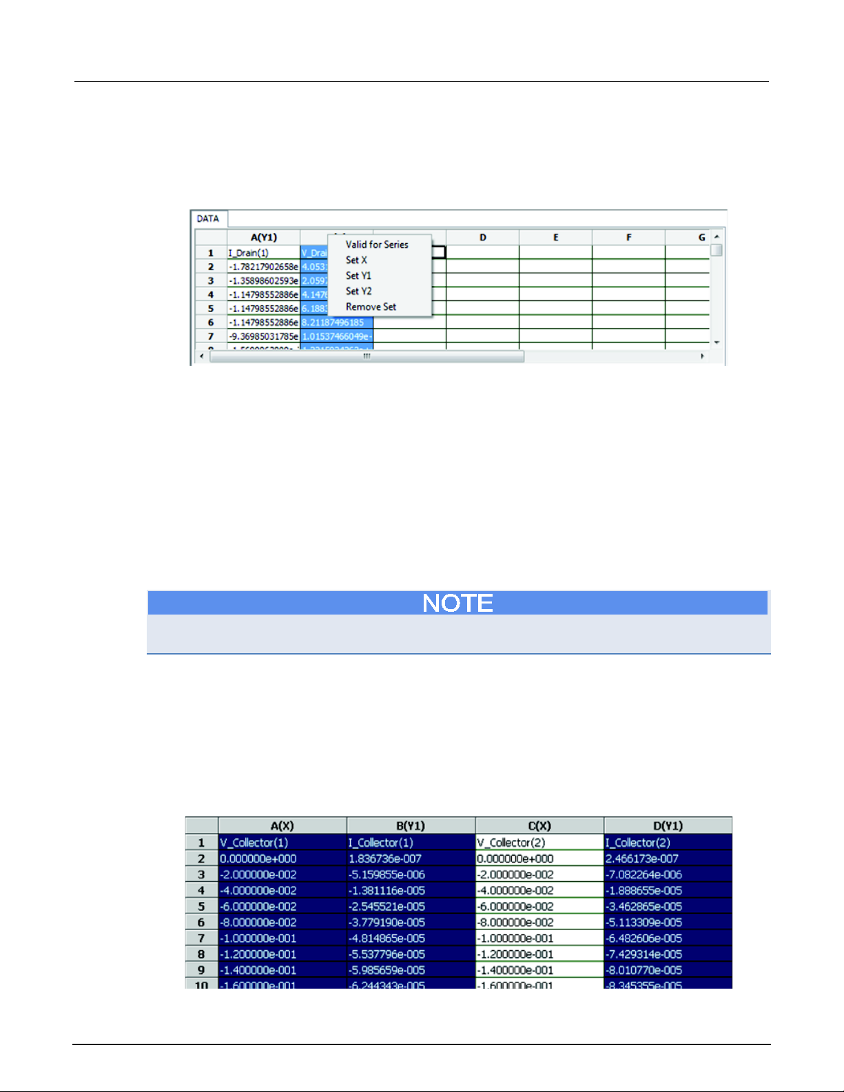
Section
Reference Manual
5: ACS Basic test setup ACS Basic Automated Characterization Suite
Assign data to an axis
Right-click on the title of any column in the data sheet to display the graph definition menu (see next
figure).
Figure 80: Graph definition menu
Graph definition menu descriptions:
Valid for Series: is used when your test is multi-step and there are a series of results (see previous
figure). If the Valid for Series command is selected, the settings for any column are valid for all of the
other columns in the same series. For example, if column B (I_Drain(1)) is set as X, column D
(I_Drain(2)) will also be set as X.
Set X: sets the selected column as the X Axis on the graph.
Set Y1: sets the selected column as the Y Axis on the left side of the graph.
Set Y2: sets the selected column as the Y Axis on the right side of the graph.
Remove Set: deletes the selected column from the plot.
To draw a graph, at least one X and one Y should be set.
ACS Basic supports multi-plot using one data sheet. This allows different columns to be plotted to
different graphs.
Assign the axis to a plot
After an axis is set, you must choose the data you want plotted on the graph. To choose data, click
the title of a column (the column will highlight).
To choose more than one column, drag the mouse over the desired columns, or execute a Ctrl + click
on the desired column. At least one X and one Y axis (either Y1 or Y2) must be selected. The next
figure shows the results of choosing multiple columns.
Figure 81: Result of data selection
5-28 ACSBASIC-901 Rev. E / August 2012
 Loading...