

Page 1
www.keithley.com
1.888.KEITHLEY (U.S. only)
Technical Data
A GREATER MEASURE OF CONFIDENCE
Page 2
www.keithley.com
1.888.KEITHLEY (U.S. only)
A GREATER MEASURE OF CONFIDENCE
Technical Data
SWITCH/MEASURE SYSTEMS
2
Integra Series Multimeter/Switch Systems
Introduction
The Integra Series of 6
1
⁄2-digit Multimeter/Switch systems blends Keithley’s high performance DMM technology, switching expertise, and data acquisition knowledge into compact, affordable, easy-to-use packages. This technical data booklet provides a comprehensive overview of the systems and includes detailed
specifications.
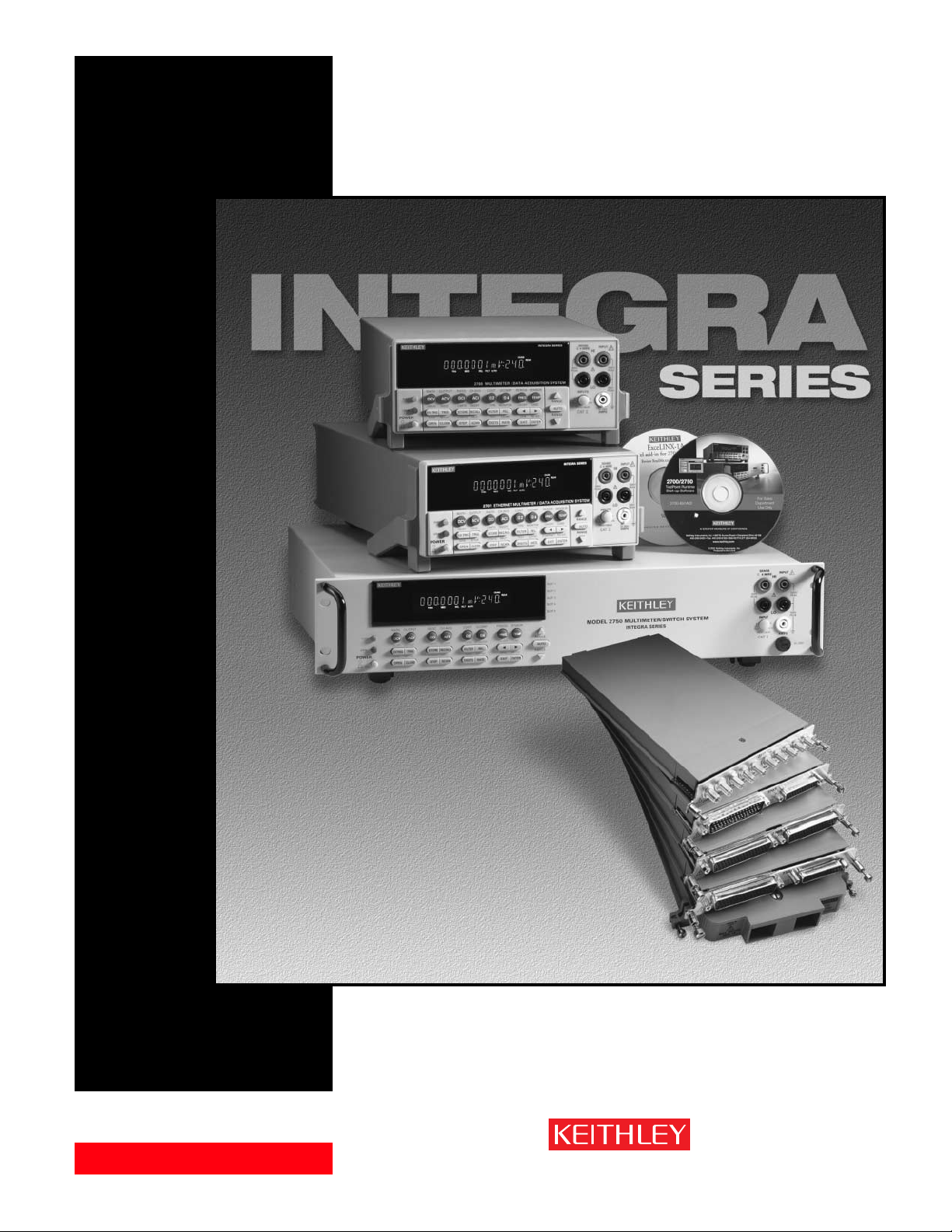
There are three Integra systems: the Model 2700, 2701, and 2750. Each consists of a mainframe and a
growing line of plug-in switch/control modules. The Model 2700 and 2701 each include two slots for the
plug-in modules; the Model 2750 has five slots. Each slot can support a series of multiplexer, matrix, or
control modules, and all the modules in a system operate simultaneously. Input modules can be mixed or
matched to provide a broad range of measurement, acquisition, and control capabilities.
While the core functionality and programming of all Integra Series systems are identical, each mainframe
has unique capabilities. For example, the Model 2701 is the only system to provide a 10/100BaseTX
Ethernet interface, and the Model 2750 provides extended low ohms measurement capability.
Setting up an Integra system is simple and straightforward. When a plug-in module is inserted into a slot,
it is ready to be used immediately. Settings can be configured from the front panel of the system or via
the computer controller (over GPIB, RS-232, or Ethernet). Also, each channel can be configured
independently.
If you have any questions after reviewing this information, please contact your local Keithley representative or call one of our Application Engineers at 1-800-552-1115 (U.S. only). Check Keithley’s website,
www.keithley.com, for the names and numbers of our representatives around the world.
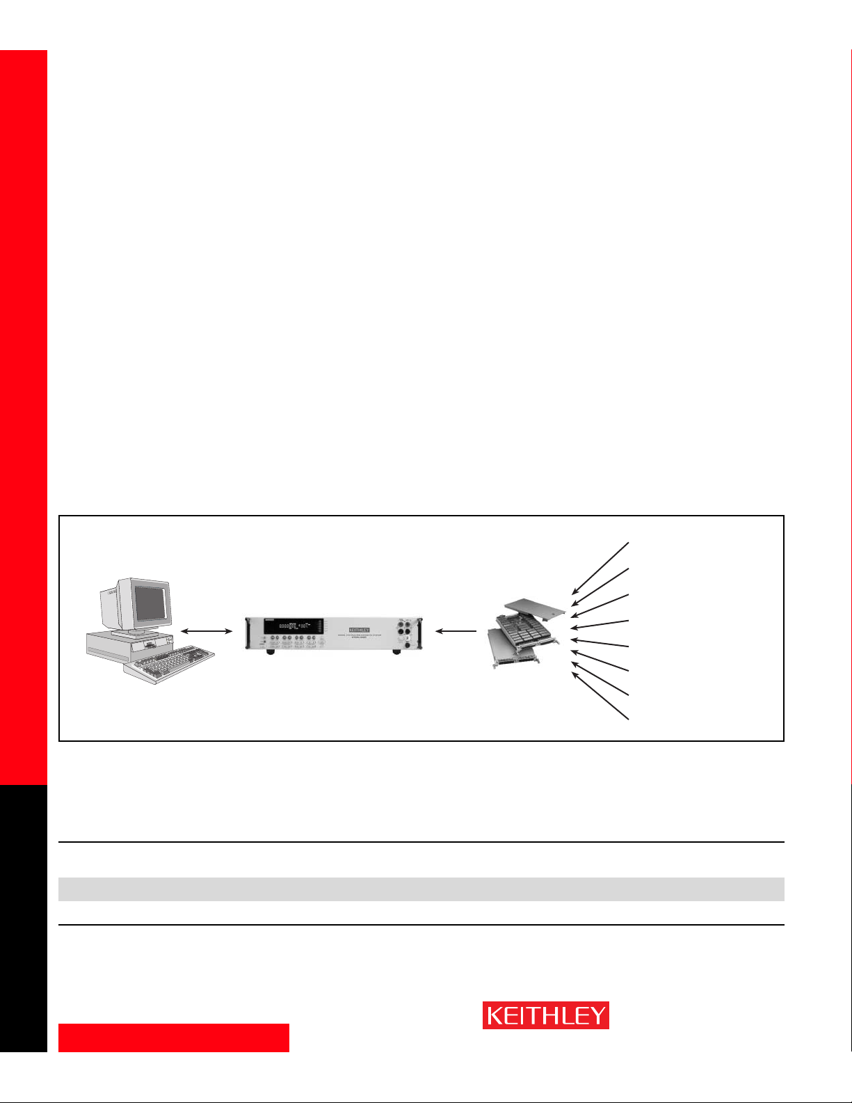
Figure 1. Typical Integra Series System Diagram
Quick Comparison of Integra Systems
Maximum
Max. No. of Measurement Speed Maximum
Communication No. of` Channels or Battery-Backed (readings/second Scanning Rate
Bus Slots Crosspoints Memory Buffer on one channel) (channels/second) Other
Model 2701 Ethernet, RS-232 2 80 channels or 450,000 readings 3500 500 Hardwired Ethernet interface good to
96 crosspoints 100m from computer or network hub.
Wireless Ethernet good for miles.
Model 2700 GPIB, RS-232 2 80 channels or 55,000 readings 2000 180
96 crosspoints
Model 2750 GPIB, RS-232 5 200 channels or 110,000 readings 2500 230 Low ohms capabilities,
240 crosspoints 1µΩ sensitivity
Integra Series System
Switch/Control
Modules
MEASURE
DCV
Ohms
Te mperature
ACV
Frequency
DC & AC Current
To talizer
CONTROL
Analog Output
Digital I/O
Multiplex Switching
Independent Switching
Matrix Switching
RF Switching
Page 3

www.keithley.com
1.888.KEITHLEY (U.S. only)
A GREATER MEASURE OF CONFIDENCE
Technical Data
SWITCH/MEASURE SYSTEMS
3
Integra Series Multimeter/Switch Systems
Table of Contents
Overview . . . . . . . . . . . . . . . . . . . . . . . . . . . . . . . . . . . . . . . . .4
Front and Rear Panel Views of Model 2700 . . . . . . . . . . . . . . . . . . . . . . . . . . .5
Front and Rear Panel Views of Model 2701 . . . . . . . . . . . . . . . . . . . . . . . . . . .6
Front and Rear Panel Views of Model 2750 . . . . . . . . . . . . . . . . . . . . . . . . . . .4
Measurement Ranges . . . . . . . . . . . . . . . . . . . . . . . . . . . . . . .7
Switch/Control Module Capabilities . . . . . . . . . . . . . . . . . . .7
Module Capabilities Overview . . . . . . . . . . . . . . . . . . . . . . . . . . . . . . . . . . . . . .7
Module Selector Guide . . . . . . . . . . . . . . . . . . . . . . . . . . . . . . . . . . . . . . . . . . . .8
Connector Guide for Keithley Integra Series Modules . . . . . . . . . . . . . . . . . .8
Channel Configuration Capabilities . . . . . . . . . . . . . . . . . . . .9
Scanning Capabilities . . . . . . . . . . . . . . . . . . . . . . . . . . . . . . .9
Choice of Communication Interfaces . . . . . . . . . . . . . . . . .10
Triggering and I/O Capabilities . . . . . . . . . . . . . . . . . . . . . . .11
Trigger Sources . . . . . . . . . . . . . . . . . . . . . . . . . . . . . . . . . . . . . . . . . . . . . . . . .11
Alarm Limits . . . . . . . . . . . . . . . . . . . . . . . . . . . . . . . . . . . . . . . . . . . . . . . . . . . .12
Digital Outputs . . . . . . . . . . . . . . . . . . . . . . . . . . . . . . . . . . . . . . . . . . . . . . . . .12
Electrical Capabilities . . . . . . . . . . . . . . . . . . . . . . . . . . . . . . . . . . . . . . . . . . . .12
On-board Data Storage . . . . . . . . . . . . . . . . . . . . . . . . . . . .12
Saving/Recalling a Setup . . . . . . . . . . . . . . . . . . . . . . . . . . .13
Power Failure Recovery . . . . . . . . . . . . . . . . . . . . . . . . . . . .13
Channel Monitor . . . . . . . . . . . . . . . . . . . . . . . . . . . . . . . . . .13
Measurement Performance . . . . . . . . . . . . . . . . . . . . . . . . .13
Filtering . . . . . . . . . . . . . . . . . . . . . . . . . . . . . . . . . . . . . . . . .14
NPLC . . . . . . . . . . . . . . . . . . . . . . . . . . . . . . . . . . . . . . . . . . .14
Line Cycle Synchronization . . . . . . . . . . . . . . . . . . . . . . . . .14
Autozero . . . . . . . . . . . . . . . . . . . . . . . . . . . . . . . . . . . . . . . .14
Low Ohms Measurement . . . . . . . . . . . . . . . . . . . . . . . . . . .14
Offset Compensation . . . . . . . . . . . . . . . . . . . . . . . . . . . . . .15
Voltage Limit/Dry Circuit Ohms (DRYCKT) . . . . . . . . . . . . .15
Te mperature Measurements . . . . . . . . . . . . . . . . . . . . . . . . .15
Calibration . . . . . . . . . . . . . . . . . . . . . . . . . . . . . . . . . . . . . . .16
Software . . . . . . . . . . . . . . . . . . . . . . . . . . . . . . . . . . . . . . . .17
Integra Series Specifications . . . . . . . . . . . . . . . . . . . . . . . .19
Switch/Control Module Specifications
7700 20-Channel Differential Multiplexer w/Automatic CJC . . . . . . . . . . . . .23
7701 32-Channel Differential Multiplexer . . . . . . . . . . . . . . . . . . . . . . . . . . . .24
7702 40-Channel Differential Multiplexer . . . . . . . . . . . . . . . . . . . . . . . . . . . .25
7703 32-Channel High Speed Differential Multiplexer . . . . . . . . . . . . . . . . .26
7705 40-Channel Control Module . . . . . . . . . . . . . . . . . . . . . . . . . . . . . . . . . .27
7706 All-in-One I/O Module . . . . . . . . . . . . . . . . . . . . . . . . . . . . . . . . . . . . . . .28
7707 Multiplexer-Digital I/O Module . . . . . . . . . . . . . . . . . . . . . . . . . . . . . . . .29
7708 40-Channel Differential Multiplexer Module . . . . . . . . . . . . . . . . . . . . .30
7709 6×8 Matrix Module . . . . . . . . . . . . . . . . . . . . . . . . . . . . . . . . . . . . . . . . .31
7710 20-Channel Solid State/Long Life Differential Multiplexer w/CJC . . . .32
7711 2GHz 50Ω RF Module . . . . . . . . . . . . . . . . . . . . . . . . . . . . . . . . . . . . . . .33
7712 3.5GHz 50Ω RF Module . . . . . . . . . . . . . . . . . . . . . . . . . . . . . . . . . . . . .34
System Configuration Examples . . . . . . . . . . . . . . . . . . . . .35
Page 4
www.keithley.com
1.888.KEITHLEY (U.S. only)
A GREATER MEASURE OF CONFIDENCE
Overview
SWITCH/MEASURE SYSTEMS
4
Integra Series Multimeter/Switch Systems
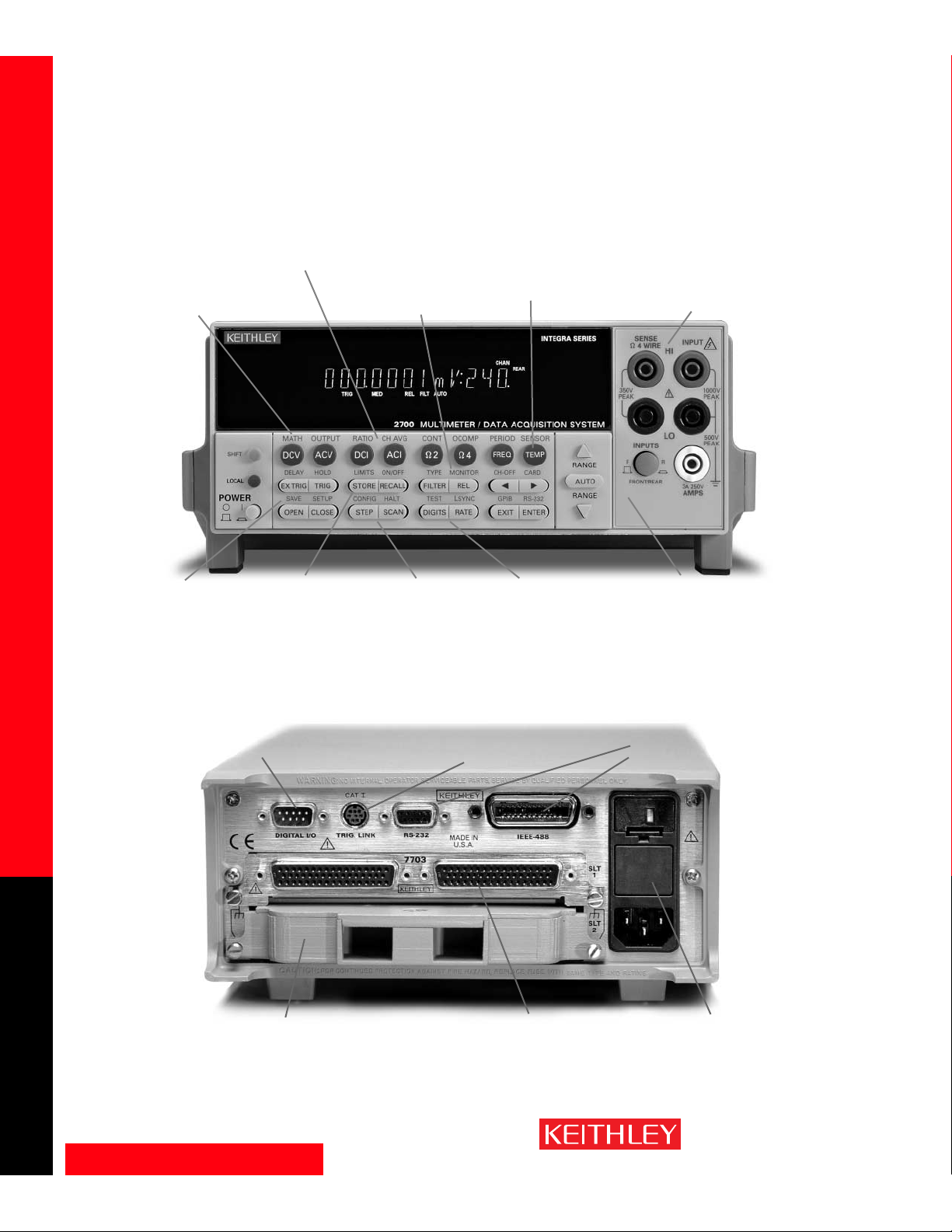
Measure the ratio
or average of two
input channels.
View a channel of
interest without
interrupting a
scan by using the
Channel Monitor
feature.
Built-in
linearization for
thermocouples,
RTDs, and
thermistors.
Front panel input jacks simplify
manual probing, troubleshooting,
and calibration. Built-in signal
conditioning with 1000V isolation
simplifies system configuration and
ensures good measurements.
Familiar DMM-like front panel
scheme makes it easier to use on
bench or rack. Select or change
functions with the simple push
of a button.
Set the number
of digits to be
displayed as well
as the reading
rate.
Non-volatile
memory allows
time-stamped
storage of 55k
readings.
Manually step
through channels
or scan
automatically.
Configure each
channel
independently.
Initialize the system
with one of four fully
programmable set-up
conditions. System
configuration is
stored in non-volatile
memory.
Use mX+b or %
scaling to convert
sensor/transducer
outputs directly
into engineering
units.
Built-in digital I/O lines provide for
control, external triggering, and
HI/LO alarm/limit outputs.
Trigger Link enables tightly
synchronized triggering with other
instruments in large ATE systems
GPIB and RS-232
interfaces are
standard.
Built-in noise rejection circuitry
ensures stable, predictable
measurements.
Rugged 50-pin D-sub
connectors ensure dependability
and quick setup/teardown in
production test racks.
A variety of measurement and control modules let you
mix, match, and change input signals or control lines
any time you like. Install up to two modules at a time
to create up to an 80-channel “mini-ATE” system.
Model 2700
Page 5
www.keithley.com
1.888.KEITHLEY (U.S. only)
A GREATER MEASURE OF CONFIDENCE
Overview
SWITCH/MEASURE SYSTEMS
5
Integra Series Multimeter/Switch Systems
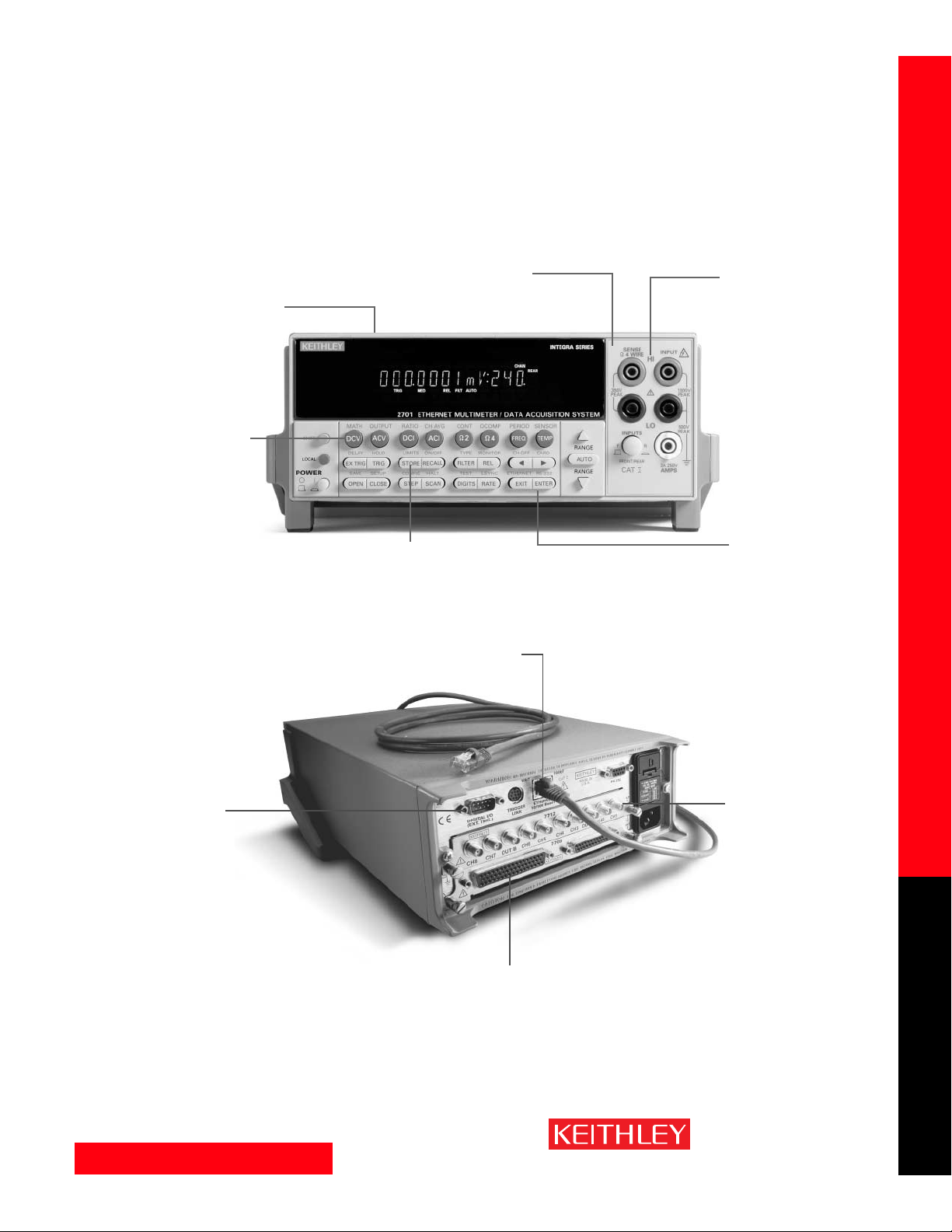
Model 2701
If there’s a power failure, valuable
data is protected with the
battery-backed non-volatile
memory and scans can
automatically be resumed right
where they stopped when
power returns.
Built-in signal conditioning
and statistical analysis is
configurable per channel
for maximum flexibility.
Its familiar DMM-like front
panel scheme makes the
Model 2701 easy to use on
the bench or in the rack.
Select or change functions
with the press of a button.
Front panel input jacks
simplify manual probing,
troubleshooting, and
calibration. Includes
1000V protection in case
of accidental overload.
Large memory buffer (450,000
readings) for storing data
without tying up the network.
Immediate alarm
notification independent
of the PC provided by
built-in open-collector
digital I/O lines for control,
external triggering, and
HI/LO alarm/limit outputs.
Built-in relay cycle counters on each
module for ease of maintenance.
A variety of measurement
and control modules makes
it simple to mix, match, and
change input signals or
control lines as needed.
Get up to 80 differential
channels and up to 500
channels per second
scanning rate.
Fast and convenient
10/100BaseTX Ethernet
with TCP/IP protocol.
Open lead detection
protects against false
readings due to lead
disconnections.
Page 6

www.keithley.com
1.888.KEITHLEY (U.S. only)
A GREATER MEASURE OF CONFIDENCE
Overview
SWITCH/MEASURE SYSTEMS
6
Integra Series Multimeter/Switch Systems
Built-in
independently
programmable
alarm limits
per channel.
View slot capacity
and channel
closure status
from front panel.
Front panel input
jacks simplify
manual probing,
troubleshooting,
and calibration.
Open lead detection
protects against
false readings
due to lead
disconnections.
Familiar DMM-like front
panel scheme makes it
easier to use on bench or
rack. Select or change
functions with the push
of a button.
1Ω range with
1µΩ resolution
Voltage clamped
ohms (dry circuit)
clamps voltage to
20mV.
Non-volatile memory allows
time-stamped storage of
110K readings. Has built-in
real-time clock.
Open or close single or
multiple channels from
the front panel.
Manually step through
channels or scan
automatically. Each
channel independently
configurable.
Initialize the system
with one of three
fully programmable
set-up conditions.
Use mX+b or 1/x %
scaling to convert
sensor/transducer
outputs directly into
engineering units.
Built-in digital I/O lines
provide for control, external
triggering, and HI/LO
alarm/limit outputs.
Trigger Link enables tightly
synchronized triggering
with other instruments in
large ATE systems.
GPIB and RS-232
interfaces are
standard.
Built-in noise rejection
circuitry ensures stable, predictable
measurements.
IDC connectors on
selected modules are
compatible with standard
ribbon cable.
Rugged D-sub
bulkhead connectors
on selected modules.
Built-in relay cycle
counters on each module
for ease of maintenance.
A variety of measurement and control
modules make it simple to mix, match, and
change input signals or control lines whenever
needed. Install up to five modules at once to
create a system of up to 200 channels.
Model 2750
Page 7
www.keithley.com
1.888.KEITHLEY (U.S. only)
A GREATER MEASURE OF CONFIDENCE
Measurement Ranges — Switch/Control Module Capabilities
SWITCH/MEASURE SYSTEMS
7
Integra Series Multimeter/Switch Systems
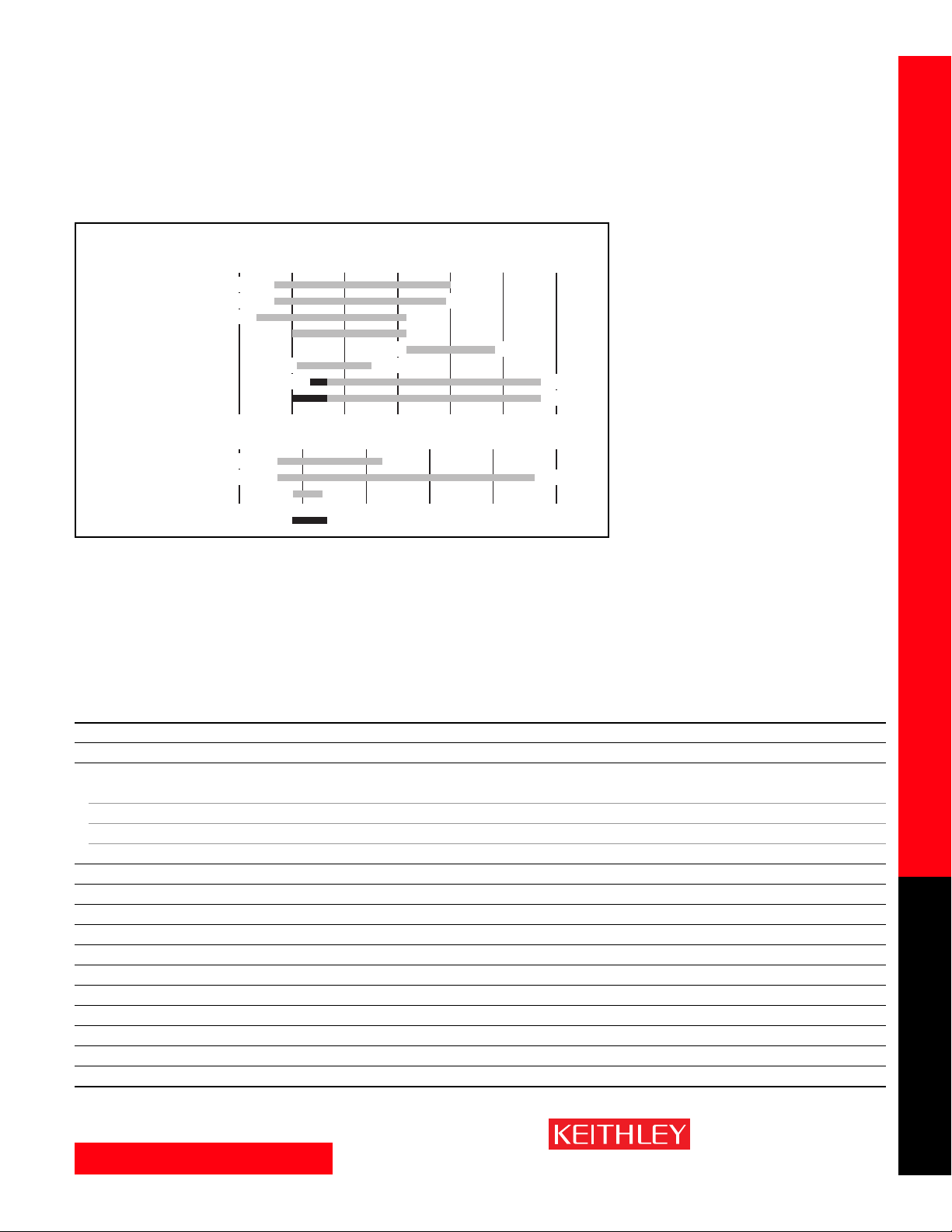
Measurement Ranges for the Integra Series Systems
Switch/Control Module Capabilities
The flexibility to mix and match switch/control modules in a single mainframe simplifies configuring
Integra Series-based systems for a wide range of applications. Each module offers a different combination
of capabilities, such as number of channels, speed, etc. Before selecting a module, it is critical to analyze
the needs of the application carefully and consider future requirements for expansion.
Figure 2. Measurement Ranges
Module Capabilities Overview
7700 7701 7702 7703 7705 7706 7707 7708 7709 7710 7711 7712
DC Volts ✓✓✓✓ ✓✓✓✓✓
DC Current ✓✓
Te mperature
T/C w/Automatic CJC ✓✓✓✓
T/C w/External CJC ✓✓✓✓ ✓✓✓✓✓
RTD ✓✓✓✓ ✓✓✓✓✓
Thermistor ✓✓✓✓ ✓✓✓✓✓
Resistance (2- or 4-wire) ✓✓✓✓ ✓✓✓✓✓
Continuity ✓✓✓✓ ✓✓✓✓✓
AC Volts ✓✓✓✓ ✓✓✓✓✓
AC Current ✓✓
Frequency ✓✓✓✓ ✓✓✓✓✓
Event Counter/Totalizer ✓
Signal Routing/Control ✓✓✓✓✓✓✓✓✓✓✓✓
Digital Input ✓
Digital Output ✓✓
Analog Output ✓
RF Performance ✓✓
Measurement Ranges
1n 1
DC Voltage
AC Voltage
DC Current
AC Current
Frequency
Period
Resistance (2-Wire)
Resistance (4-Wire)
Logarithmic scale
Temperature–RTD
Temperature–TC
Temperature–Thermistor
Linear scale
10nA 3A
–500 0 500 1000 1500 2000
100nV 1000V
100nV 750V
–200°C 630°C
–200°C 1820°C
µ
1m 1 1k 1M 1G
1µA 3A
3Hz 500kHz
2µs 333ms
µΩ
10
µΩ
1
–80°C 150°C
Model 2750 only
120M
120M
Ω
Ω
Page 8

www.keithley.com
1.888.KEITHLEY (U.S. only)
A GREATER MEASURE OF CONFIDENCE
Switch/Control Module Capabilities
SWITCH/MEASURE SYSTEMS
8
Integra Series Multimeter/Switch Systems
Module Selector Guide
This selector guide may prove helpful in identifying the best module for a specific application. Install up to five
modules at a time in the Model 2750 mainframe or two modules in the Model 2700 or 2701 mainframe.
Max.
# Analog Type of Max. Switched Contact Switch
Module Inputs Configuration Connector Voltage Current Bandwidth Life Speed Other
7700 20 Multiplexer 1×20 or Screw 300 V 1 50 MHz 10
8
3 ms Maximum power = 125VA.
w/CJC two 1×10 terminals 2 current measure channels.
7701 32 Multiplexer 1×32 or D-sub 150 V 1 A 2 MHz 10
8
3 ms Maximum power = 125VA.
two 1×16
7702 40 Multiplexer 1×40 or Screw 300 V 1 A 2 MHz 10
8
3 ms Maximum power = 125VA.
two 1×20 terminals 2 current measure channels.
7703 32 Multiplexer 1×32 or D-sub 300 V 500 mA 2 MHz 10
8
1 ms Reed relays.
two 1×16
7705 40 Independent N/A D-sub 300 V 2A 10 MHz 10
8
3 ms Maximum power = 125VA.
SPST
7706 20 Multiplexer 1×20 or Screw 300 V 1 A 2 MHz 10
8
3 ms 2 analog outputs.
w/CJC two 1×10 terminals 16 digital outputs.
Maximum power = 125VA.
7707 10 Multiplexer/ 1×10 or D -sub 300 V 1 A 2 MHz 10
8
3 ms 32 digital I/O.
Digital I/O two 1×5 Maximum power = 125VA.
7708 40 Multiplexer 1×40 or Screw 300 V 1 A 2 MHz 10
8
3 ms Maximum power = 125VA.
w/CJC two 1×20 terminals
7709 48 Matrix 6×8D-sub 300 V 1 A 2 MHz 10
8
3 ms Connects to internal DMM.
Daisy chain multiple cards
for up to a 6×40 matrix.
Maximum power = 125VA.
7710 20 Multiplexer 1×20 or Removable 60 V 0.1 A 2 MHz 10
10
0.5 ms Solid state relays, 60V max.
w/CJC two 1×10 screw 500 channels/second scan rate.
terminals
7711 8 Multiplexer Dual 1×4 SMA 60 V 0.5 A 2 GHz 10
6
10 ms Insertion loss <1.0dB @ 1GHz.
VSWR <1.2 @ 1GHz.
7712 8 Multiplexer Dual 1×4 SMA 42 V 0.5 A 3.5 GHz 10
6
10 ms Insertion loss <1.1dB @ 2.4GHz.
* Can be disconnected from internal DMM for routing external signals
Connector Guide for Keithley Integra Series Modules
Module Connector Type Supplied Accessories Available Accessories
7700 Oversized Screw Terminal Strain Relief 7401 TC wire
7701 50-pin female D-sub & 25-pin female D-sub 7789 connector kit 7790 connector kit, 7705-MTC-2 & 7707-MTC-2 cables
7702 Oversized Screw Terminal Strain Relief —
7703 Two 50-pin female D -sub 7788 connector kit 7705-MTC-2 cable
7705 Two 50-pin female D -sub 7788 connector kit 7705-MTC-2 cable
7706 Screw Terminal Strain Relief 7401 TC wire
7707 50-pin male D-sub & 25-pin female D-sub 7790 connector kit 7789 connector kit, 7705-MTC-2 & 7707-MTC-2 cables
7708 Oversized Screw Terminal Strain Relief 7401 TC wire kit
7709 50-pin female D-sub & 25-pin female D-sub 7790 connector kit 7789 connector kit, 7705-MTC-2 & 7707-MTC-2 cables
7710 Quick Disconnect Screw Terminal Strain Relief 7401 TC wire kit
7711 SMA — 7711-BNC-SMA & 7712-SMA-N adaptors, 7712-SMA-1 & S46-SMA-0.5,-1 SMA cables,
7051-2,-5,-10 BNC cables
7712 SMA — 7712-SMA-N adaptor, 7712-SMA-1 & S46-SMA-0.5,-1 SMA cables
Page 9
www.keithley.com
1.888.KEITHLEY (U.S. only)
A GREATER MEASURE OF CONFIDENCE
Channel Configuration Capabilities — Scanning Capabilities
SWITCH/MEASURE SYSTEMS
9
Integra Series Multimeter/Switch Systems
Channel Configuration Capabilities
• Measurement functions: An Integra system can measure many different parameters: DC voltage, DC
current, AC voltage, AC current, 2-wire Ω, 4-wire Ω, voltage clamped Ω (2750 only), temperature
(using thermocouples, RTDs, and thermistors), frequency, period, and continuity.
• Math functions: A variety of math functions are available at the push of a button, including channel
average and ratio, mX+b scaling, min, max, average and standard deviation. All are available on a per-
channel basis.
• Measurement setup: Each channel can be configured independently for making measurements.
Selectable channel parameters include:
• Speed
•Range
• Resolution
• Number of power line cycles
(NPLC)
• Math functions
•Ratio calculation
• Individual “m” and “b” values in mX+b format
• Channel averaging
•Hi-Low limits
• Resistance measurement
method (2- or 4-wire)
• Offset compensation
• CJC type
• Thermistor type
• Thermocouple type
•RTD type
•Voltage clamped ohms
(Dry Circuit, 2750 only)
• DUT-to-modules connections: It is easy to connect the device under test to the switch/control modules. The 7703 and 7705 modules use dual 50-pin “D-sub” input connectors for secure, quick connections. The 7701, 7707, and 7709 modules use “D-sub” connectors that are compatible with off-the-shelf
standard ribbon cable. These connectors are especially convenient for rapid system setup. When
greater connection flexibility is required, the 7700, 7702, and 7708 modules provide oversize screw
terminal connectors that simplify setup by eliminating the need to handle small connectors. The standard wires used are 20AWG. Model 7710 uses removable terminal blocks to provide the simplicity of
screw terminal connections with the speed of mass terminated cables. The 7711 and 7712 RF modules
use industry standard SMA connectors.
• Mainframe-to-modules connection: Secure screws connect the modules to the mainframe. At
power-up, the mainframe detects any attached modules automatically, which minimizes set-up time. All
signals are routed internally from module to mainframe.
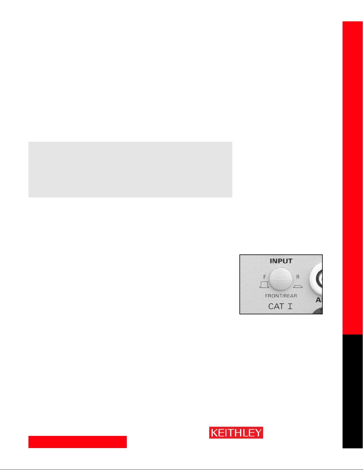
• Front/rear switch: The front inputs are used for manual probing, troubleshooting, and calibration. A
switch on the front panel makes it easy to shift between the front and rear inputs. This eases setting
up the equipment and speeds verifying proper setup and connections prior to automating the
measurement.
Scanning Capabilities
•Relay Closure Counts: Relay closure counts are logged every time a channel is closed. These counts
are permanently written to the EEPROM on the module at a user-settable time interval (factory default
of 10 minutes) or whenever the counts are queried. Valid intervals (set in integer number of minutes)
are between 1 and 1440 minutes (24 hours). Relay closures are counted when a relay cycles from open
to closed state.
• Open Sense Lead Indication. The system can alert the user if there is a sense lead disconnection
on any channel. In this case, the front panel display will show “OVERFLOW.” Therefore, the system
does not need other equipment or calibration to inspect the broken connection or failed relay on the
scanner card. In addition, the system will protect against erroneously passed conditions.
• Scan count: An Integra Series system can be programmed to run a given number of scans (up to
450,000) automatically and to record readings into the internal memory buffer. The instrument also
allows programming the trigger source used to initiate each scan. (Refer to page 11 for more information on triggering.)
Page 10
www.keithley.com
1.888.KEITHLEY (U.S. only)
A GREATER MEASURE OF CONFIDENCE
Scanning Capabilities — Choice of Communication Interfaces
SWITCH/MEASURE SYSTEMS
10
Integra Series Multimeter/Switch Systems
• Scan interval: The user can set the interval after which each succeeding scan will begin. Scan intervals can be set anywhere from 0 to 99 hours in increments of 1ms.
• Scan sequence/omitting channels: In addition to scanning in numerical sequence, the system can
be programmed to skip any channels that are not required for a particular test. This avoids recording
irrelevant data and speeds the data acquisition process. This makes scanning both faster and more flexible.
• Ratio (DCV only): The instrument can calculate and display the ratio of measurements of paired
channels. Ratios can only be determined for specific channel pairs, depending upon the input module
used. For example, channel pairs on the Model 7702 include Channels 1 and 21, Channels 2 and 22,
etc. Hi/Lo limits are fully supported.
• Channel average (DCV and thermocouple only): The instrument can calculate and display the
average of two channel measurements. As with ratio calculations, only paired channels can be averaged. Hi/Lo limits are fully supported.
Choice of Communication Interfaces
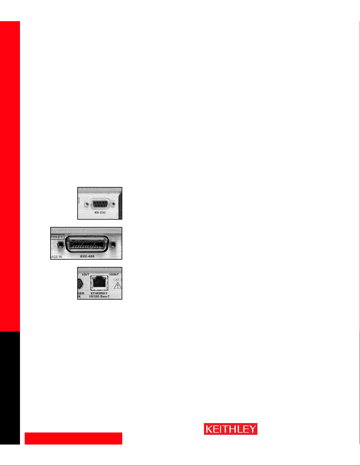
RS-232
All the Integra Series mainframes include RS-232 ports for computer control. RS-232 is a low cost point-topoint interface, allowing a computer to interface with a one mainframe per port at distances up to several
hundred meters, depending on the baud rate setting. Slow baud rates can be run long distances, while
the fastest baud rate settings are limited to several meters maximum distance. The Model 2700 and 2750
can receive commands and transfer data via RS-232 at various baud rates up to 19.2kBaud. The Model
2701 offers data rates up to 115.2kBaud with hardware handshaking.
GPIB
The Model 2700 and 2750 both offer a GPIB port. GPIB provides higher speed data transfers (up to
1Mbyte/sec.) than RS-232, and allows up to 32 devices to addressed from a single GPIB controller card in
a host computer. The maximum cabling distance for the GPIB interface is 2 meters between each GPIB
connection. Up to 20 total meters of cable may be connected to a single controller card.
Ethernet
The Model 2701 offers a 10/100 BaseT Ethernet connection for high speed and long distance communication between a computer and a virtually infinite number of instruments. Any PC with an Ethernet port can
connect to a single Model 2701 in a point-to-point configuration, to multiple 2701s through a hub, or to
multiple 2701s distributed on a network. See the system configuration section on page 35 for more
details on Ethernet connections.
The Model 2701 Ethernet port uses the industry-standard TCP/IP socket interface. This provides data
rates up 100Mbits/sec. and allows the instrument to be located up to 100 meters from the nearest
computer or network hub in hardwired systems and miles in wireless Ethernet systems. The maximum
distances between a control PC and the instruments are limited only by the size of the network. The
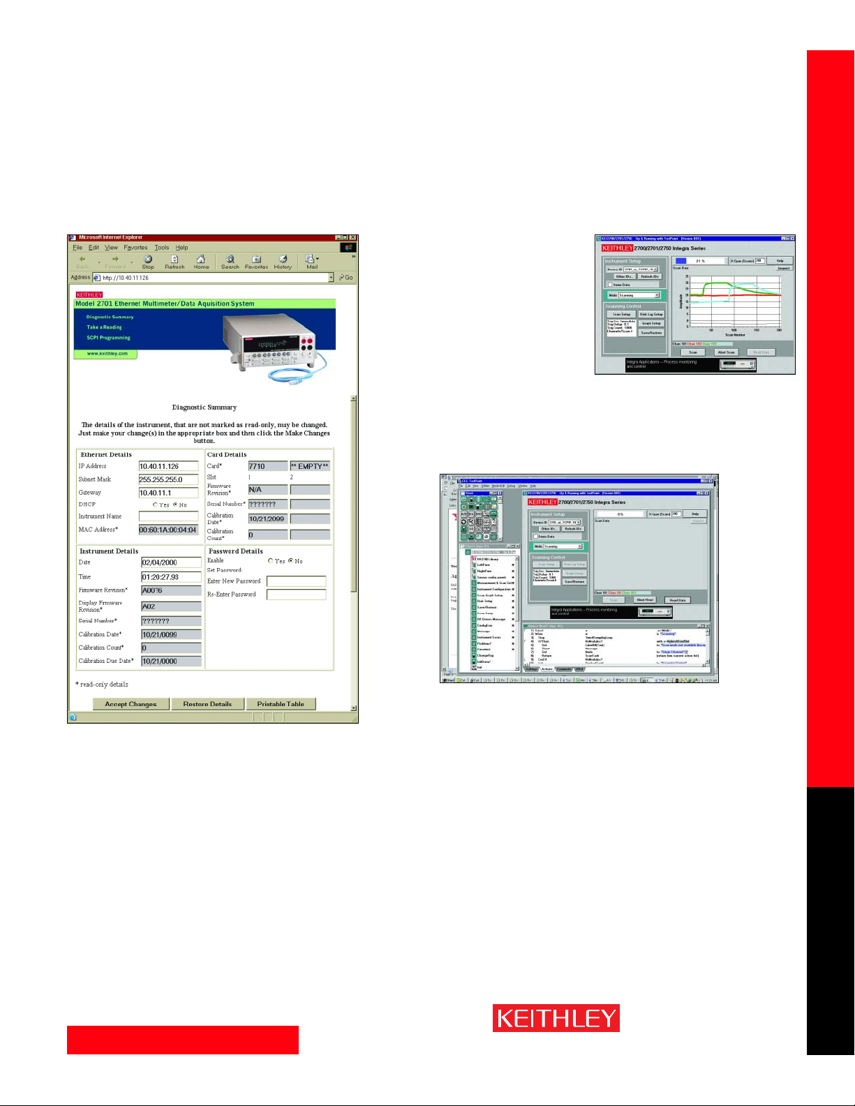
instrument also provides a built-in diagnostic web page for easy remote access to the 2701. Entering the
instrument’s IP address in the URL line of Microsoft
®
Internet Explorer®will allow communication with
and control of the 2701. This Web page allows users to read and set network parameters, such as IP
address, subnet mask, gateway, MAC address, and calibration dates, and to send commands to and query
data from the 2701.
Page 11
www.keithley.com
1.888.KEITHLEY (U.S. only)
A GREATER MEASURE OF CONFIDENCE
Triggering and I/O Capabilities
SWITCH/MEASURE SYSTEMS
11
Integra Series Multimeter/Switch Systems
Triggering and I/O Capabilities
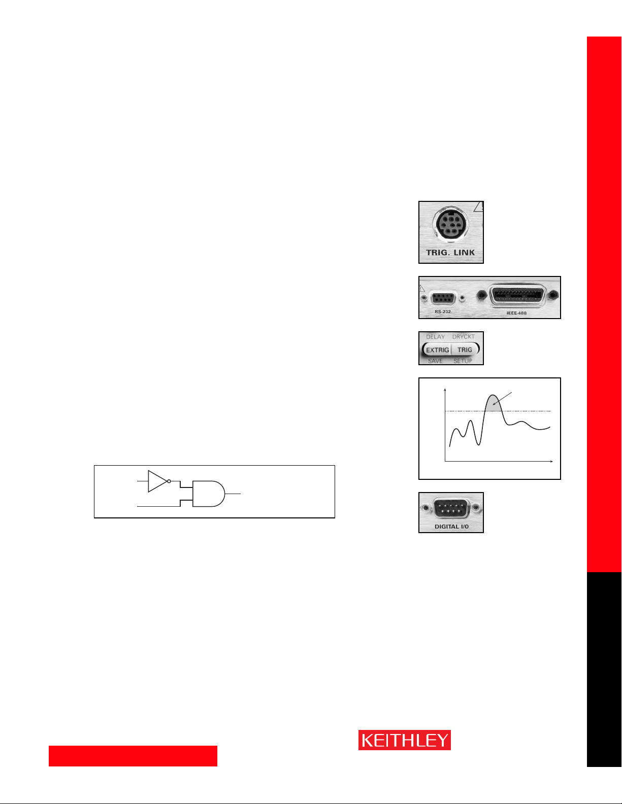
Trigger sources
Any of the following sources can be used for triggering a reading or scan sequence:
A. Immediate: An Integra Series system self-triggers automatically. This default method is the simplest
way to take a measurement on a single channel.
B. An external trigger is received via the Trigger Link connector. Triggering through Trigger Link
is very precise (<0.5ms trigger latency) and provides tight timing control for synchronization
in larger systems. Therefore, measurements can be taken at a precise time with very little uncertainty. This capability can be valuable when optimizing coordination with other system instruments, such
as the Model 2400 SourceMeter
®
instrument in larger rack & stack applications.
C. A bus trigger is received (GET or *TRG) on GPIB or *TRG on RS-232 and Ethernet.
D. Manual: Use of front panel TRIG key.
E. Analog trigger: A display reading on a particular channel can be programmed as an analog trigger. A
scan sequence is started whenever such a reading is reached [programmed for either a greater than
(>) or less than (<) condition as a trigger]. In other words, this feature can be used to initiate a scan
sequence based on some external factor, such as a temperature rising above a pre-set limit. After scanning all the configured channels on the instrument, the instrument then returns to the channel that
acted as the analog trigger, and checks for the reading to be in conditional limits. Depending on the
limits and current reading, the instrument decides whether to start the next scan. Only the data of
interest are acquired, eliminating the need to spend hours searching through reams of normal readings to find anomalous data.
F. Digital trigger: Two digital inputs (TTL-level) are standard on each mainframe—one
to serve as a trigger input and one to serve as a hardware interlock. The digital trigger is logical “and”ed with the interlock. The interlock is default true. Therefore, the digital trigger input would be recognized for triggering only when the digital trigger and the interlock are both true. Thus, the interlock
provides the user with a controlling mechanism for recognizing the digital trigger if necessary (see
Figure 3).
B
C
D
E
F
Hardware
Interlock
Trigger
Event
To Integra Series System
Microprocessor
Figure 3
Value
Scan
Time
Page 12
www.keithley.com
1.888.KEITHLEY (U.S. only)
A GREATER MEASURE OF CONFIDENCE
SWITCH/MEASURE SYSTEMS
12
Integra Series Multimeter/Switch Systems
Alarm Limits/Digital Outputs
The digital output lines can trigger external alarms without the need for a PC connection. The instrument
can be programmed to provide alarms when any pre-set limits are breached. Limits can be applied to all
measurement functions except continuity, which has its own alarm beeper. The limit test is performed
after “mX + b” and math operations.
Limit types: Each channel has four independently programmable limits, each of which can be assigned a
value. These are:
1. Limit1 High (for example, 1% higher than the expected reading)
2. Limit1 Low (for example, 1% less than the expected reading)
3. Limit2 High (for example, 5% higher than the expected reading)
4. Limit2 Low (for example, 5% less than the expected reading)
The outputs can be positive or negative true, pulse, or fixed level. Pulse widths are programmable.
Master Limit: In addition to these limit alarms, a master limit is provided. It is logically
“or”-ed with the four limits and is active every time any of the other limits are breached.
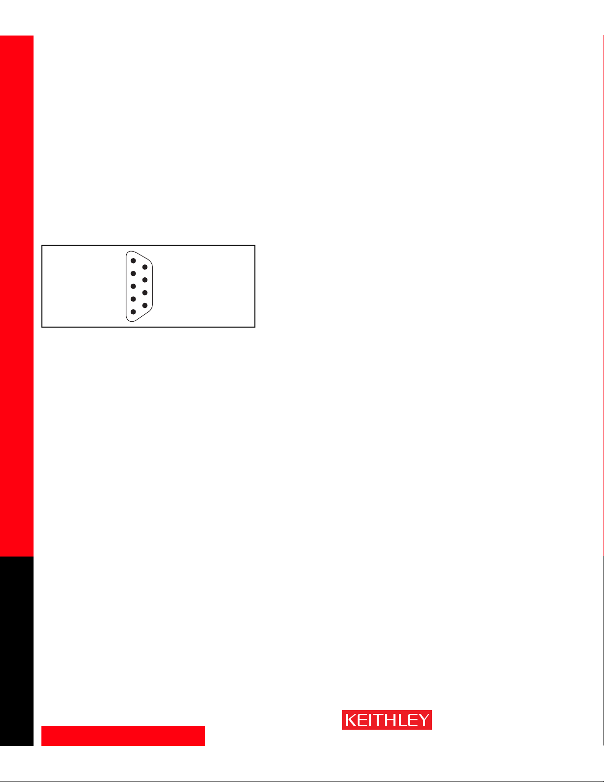
Each of the alarm limits and the master alarm is mapped to a specific output pin on the
9-pin male connector that handles the output of that alarm limit.
Electrical Capabilities:
• 250mA sink (output).
• TTL level outputs (no external supply is needed).
• Open collector output up to 33V with external supply.
• Ability to trigger or start a scan by connecting to one of the digital input lines.
On-board Data Storage
Buffer: There are non-volatile “read and transmit” memory buffers (in other words, the buffer can be
emptied while it is being filled) in each system. The buffer can be configured in “wrap around” mode for
recording readings continuously for long periods. There is no need to stop taking data, reset the instrument, or change memory cards. The wrap around memory can be configured to issue a Service Request
(SRQ) at predetermined points in the scan. An SRQ can be issued when the buffer is one-quarter full,
one-half full, three-quarters full, or completely full. The instrument can be commanded to download the
readings without interfering with the current acquisition; therefore, data acquisition and retrieval can
occur simultaneously. When the buffer is full, the instrument returns to the beginning of the buffer and
starts writing in the locations emptied by the previous download.
Timestamp: The readings in the memory can be timestamped to trace the progress of a test. The time
can be configured as either:
• Real time: The actual calendar day and time.
• Relative Time: Time is relative to the first reading stored in the buffer.
Triggering and I/O Capabilities — On-board Data Storage
Figure 4. Structure of the 9-Pin Male Digital I/O
Connector
Master Limit Alarm
Limit 2 Low Alarm
Limit 2 High Alarm
Limit 1 Low Alarm
Limit 1 High Alarm
5
4
3
2
1
Ground
9
Interlock (input pin)
8
Flyback Protection Diode
7
External Trigger (input pin)
6
Page 13
www.keithley.com
1.888.KEITHLEY (U.S. only)
A GREATER MEASURE OF CONFIDENCE
SWITCH/MEASURE SYSTEMS
13
Integra Series Multimeter/Switch Systems
Saving/Recalling a Setup
All current set-up information for individual channels and the mainframe is battery backed and the measurement data is stored in the non-volatile memory. Therefore, while the instrument is switched off, the
configuration for each channel is saved in the memory, then automatically recalled when the product is
switched on again. Up to five (four for Model 2700 and three for Model 2750) different sets of setups can
be recorded for each channel, so it’s unnecessary to set up each channel before a different test.
Power Failure Recovery
All set-up information is battery backed and data is stored in non-volatile RAM, so the system is immune
to power failures and can resume scanning where it stopped once power is restored. There is no need to
restart interrupted tests from the beginning. The scan resumption feature is user-selectable.
Channel Monitor
The channel monitor feature allows monitoring any specific input channel on the front panel display at
any time during a scan. The system can scan across channels very rapidly, so the channel monitor offers a
convenient way to view only the channel of interest without interrupting a scan.
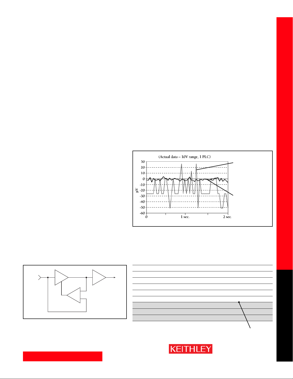
Keithley’s patented measurement
engine provides
true 6
1
⁄2-digit (22bit) performance
under similar
conditions.
Typical 6
1
⁄2-digit
meters actually
deliver 5
1
⁄2-digit
(≤18-bit) perfor-
mance at faster
reading rates.
Figure 5. When the measurements matter, Keithley provides up to 10x better
performance at equivalent reading rates or up to 10x faster speeds at equivalent
measurement performance. Our patented A/D converter and high performance
signal conditioning circuitry make this possible.
Specification Conversion Factors
Percent PPM Digits Bits dB Portion of 10V
10% 100000 1 3.3 –20 1 V
1% 10000 2 6.6 –40 100 mV
0.1% 1000 3 10 –60 10 mV
0.01% 100 4 13.3 –80 1 mV
0.001% 10 5 16.6 –100 100 µV
0.0001% 1 6 19.9 –120 10 µV
0.00001% 0.1 7 23.3 –140 1 µV
0.000001% 0.01 8 26.6 –160 100 nV
0.0000001% 0.001 9 29.9 –180 10 nV
Integra Series Performance
(61⁄2-digit, 22-bit)
Figure 6.
Measurement Performance
Each Interga series system is a true 61⁄
2-digit (22-bit) instrument
designed for high measurement precision. Its high precision
enhances measurement repeatability and stability.
Measurement performance is a key advantage of all of Keithley’s
products. The Integra Series is based on a number of advanced
technologies that improve its overall performance dramatically,
including:
• Patented A/D converter IC circuitry design to increase the resolution, precision, and speed of measurement.
• Advanced signal conditioning hardware to filter out unwanted
noise and provide necessary isolation.
•A unique “servo” front end design (Figure 6). While conventional DMMs typically measure and correct for the zero drift of
front-end circuitry, these systems’ servo front end eliminates
zero drift, which also eliminates the wasted measurement time
usually required to check zero, further increasing measurement
speed.
Saving/Recalling a Setup — Power Failure Recovery — Channel Monitor — Measurement Performance
Input
Servo
Correction
Amplifier
To A/ D
Gain
x1
–
+
x10
x100
Page 14
www.keithley.com
1.888.KEITHLEY (U.S. only)
A GREATER MEASURE OF CONFIDENCE
Digital Filtering — NPLC — Line Cycle Synchronization — Autozero — Low Ohms Measurement
SWITCH/MEASURE SYSTEMS
14
Integra Series Multimeter/Switch Systems
Digital Filtering
For each major measurement function, users can employ either averaging or advanced digital filtering to
reduce noise and increase the effective resolution.
Averaging Filter
The averaging filter operates over a range of from two to 100 readings. All readings included in the filter
range are weighted equally. A step input of any size will ramp up linearly to the final value after obtaining
the number of readings specified by the user. The averaging filter may be configured as either a moving
averaging or as a repeat filter. Operation over the GPIB bus is often done in “repeat” mode to ensure that
all readings are fully filtered. Also, taking filtered measurements in repeat mode requires only one trigger,
simplifying programming. Only the repeat filter can be used while scanning.
Advanced Filter
When a DMM is used in bench mode, it’s often desirable for it to respond immediately upon connection
to a test point, without the slow response associated with an averaging filter. The advanced filter addresses this need by providing a filter reset level. If the measured value deviates significantly from previous
values, the filter is reset to the new value, and filtering is restarted. In this way, the user can set the filter
reset level just above the maximum noise level anticipated and the multimeter will respond to new values
immediately.
NPLC
Selectable power line cycle integration allows the user to specify the number of power line cycles (NPLC)
over which to integrate (1, 5, 10, etc.). Use of line cycle integration provides rejection of noise from line
cycle interference, the most common source of noisy readings. In general, the longer the integration time
chosen, the greater the noise rejection will be. The system can also be set to less than 1 NPLC integration
time, as fast as 0.002 NPLC (~33µs at 60Hz) in the Model 2701 and 0.01 NPLC (~167µs at 60Hz) in the
Model 2700 and 2750 for faster data measurement (but without power line noise rejection).
Line Cycle Synchronization
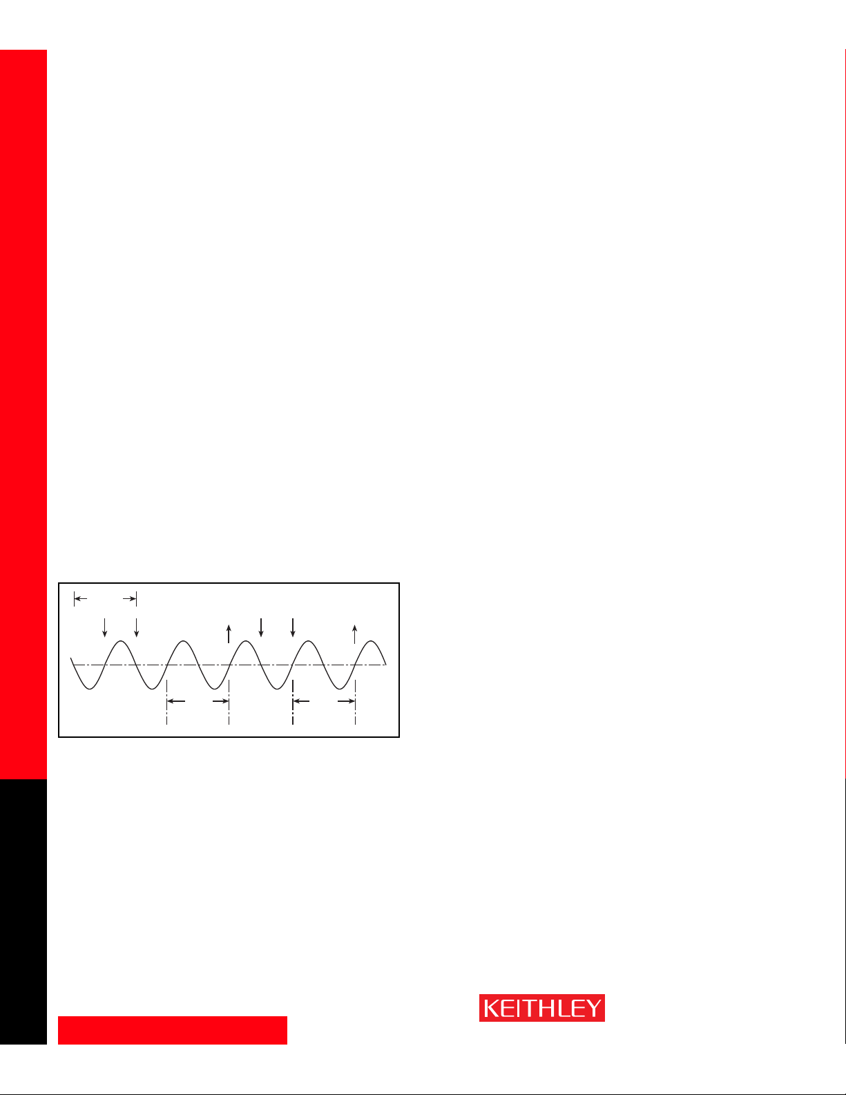
To attain the highest possible line cycle noise rejection, it is important to trigger
the reading at the beginning of a power line cycle. The system can be set to start
a measurement precisely when the power line signal crosses zero (see Figure
7). This function increases the normal mode noise rejection 30dB, providing an
additional ×30 reduction in noise due to line cycle interference.
Autozero
Internal autozeroing is used to maintain the best measurement performance.
The advanced firmware design does the required calculation, such as CJC com-
pensation for thermocouple measurements with the 7700, 7706, 7708, and
7710, automatically in the background. This enables the Integra system to provide faster reading rates
(competitive products spend half their measurement time validating their own zero). Autozero can be
disabled to increase measurement speed, but this may result in greater measurement uncertainty.
Low Ohms Measurement (Model 2750 only)
The Model 2750 can measure low ohms on all of its switch/control modules that have multiplexers or
matrix configurations. The four-wire ohms measurement supports low ohms measurements down to the
1Ω range, with micro-ohm resolution. Measurements can be accommodated through ribbon cable or
discrete wiring. On four-wire ohms measurements, up to five additional ohms of cable/switch card resistance can be tolerated per cable lead. This allows the use of ribbon cable without overloading the range.
Figure 7
1 PLC
Trigger
# 1
A/D
Conversion
Reading
Done
Reading
Trigger
# 2
Conversion
Done
A/D
Page 15

www.keithley.com
1.888.KEITHLEY (U.S. only)
A GREATER MEASURE OF CONFIDENCE
Offset Compensation — Voltage Limit/Dry Circuit Ohms — Temperature Measurements
SWITCH/MEASURE SYSTEMS
15
Integra Series Multimeter/Switch Systems
Offset Compensation
For more accurate low resistance measurements, all Integra systems provide the offset compensation
mode to eliminate errors from the thermoelectric EMF effects (V
EMF
). During the measurement cycle, the
built-in ohms current source is turned off, then turned on again, and the resulting EMF error is automati-
cally subtracted. This technique is typically used when measuring values less than 100Ω using the four-
wire ohms method.
Voltage Limit/Dry Circuit Ohms (Model 2750 only)
The use of dry circuit mode, when selected, limits the open-circuit voltage to 20mV. This allows resistance
measurements to be made with low power. When measuring contact and connector resistances, it is
important not to puncture oxides and films that may have formed. Standard resistance measurements
have open-circuit voltage levels from 5.4V to 12.8V, depending on the selected range.
Dry circuit ohms can be used on the 1Ω, 10Ω, 100Ω, and 1kΩ ranges for the four-wire ohms (Ω4) func-
tion. Also, offset compensated ohms (OCOMP) can be used with dry circuit ohms to cancel the effect of
thermoelectric EMFs.
Dry circuit ohms should be used for any device that could be damaged by high open-circuit voltage. If
not sure, and the slightly degraded accuracy is not a consideration, it is good practice to use dry circuit
ohms to measure low resistance.
The accuracy specifications for all dry circuit ohms ranges are with offset compensated ohms and line synchronization enabled.
Temperature Measurements
The Integra systems support three major types of temperature sensors with built-in signal conditioning
and linearization: thermocouples, RTDs, and thermistors.
Thermocouples RTDs Thermistors
Temperature Range –200 ~ 1820°C –200 ~ 630°C –80 ~ 150°C
Advantage • Self-powered • High stability • Interchangeability
• Wide temperature • High accuracy • No CJC required
range • No CJC required • High accuracy over
limited temperature
range
Cost LowHigh Medium
The Integra systems provide built-in algorithms for a variety of thermocouples, RTDs, and thermistors. To
begin using a sensor, simply hook it up and the system does the rest.
• Thermocouples: Type J, K, N, T, E, R, S, B
•RTDs: D100, F100, PT100, PT385, PT3916, or user type
• Thermistors: 2250Ω, 5kΩ, and 10kΩ
Page 16

www.keithley.com
1.888.KEITHLEY (U.S. only)
A GREATER MEASURE OF CONFIDENCE
Temperature Measurements — Calibration
SWITCH/MEASURE SYSTEMS
16
Integra Series Multimeter/Switch Systems
Cold Junction Compensation Methods
Thermocouple measurements always require that the temperature be known at the point where the
thermocouple is connected to the instrument. This connection point is known as the “cold junction.”
The Integra systems support three different methods for including this “cold-junction” temperature in the
temperature measurements.
Automatic CJC
The CJC sensors are mounted on the multiplexer module’s PC board (7700, 7706, 7708, and 7710).
They sense the actual temperature across the module’s connector, then compensate all temperature
measurements accordingly. The CJC scaling is done automatically when autozero is turned on, so the
user does not have to acquire it separately. When autozero is turned off, the instrument is optimized
for speed and does not refresh the CJC compensation. This allows the user to obtain faster scan rates
for short periods of time while ambient temperature remains stable.
External CJC
A thermistor or RTD is attached to Channel 1 by the end user. This thermistor or RTD is then used to
measure the temperature of the point(s) where the thermocouples are connected to the instrument
or to copper wires leading to the instrument. The precision of the actual temperature measurement
depends on the accuracy of the cold junction reading and how close the sensor is to the actual temperature of the connection.
Simulated CJC
When the “change” in temperature is of interest rather than the absolute temperature value, the user
can enter a parameter as a cold junction reference point (for example, 23°C for room temperature).
This parameter will be used to adjust the actual temperature measurement for each channel. This simulated temperature must be updated manually if ambient conditions change. This is also the method
used when an actual ice bath is used to establish a cold junction of 0°C. The simulated parameter is
then set to 0°C or 32°F.
Open Thermocouple Detect
A system can alert the user if any thermocouple becomes broken or otherwise disconnected from the
input terminal blocks. When the Open T/C Detect feature is enabled, the system will perform (in the
background) a two-wire resistance measurement across each thermocouple input channel. If an open
connection is detected, the front panel display will show “OVERFLOW” for that channel.
Calibration
The design of the Integra Series and their calibration procedure were developed to address a variety of
critical calibration issues. For example, the systems have front panel input jacks, so there’s no need to disassemble the system for periodic recalibrations. There’s also no need to buy, stock, and track spare “cal
only” modules. The systems are connected to the calibrator through the front panel input jacks. The systems’ calibration procedure covers both verification and adjustment and can be performed through either
the front panel or any of the remote interfaces. The calibration interval is user-selectable.
Page 17
www.keithley.com
1.888.KEITHLEY (U.S. only)
A GREATER MEASURE OF CONFIDENCE
Software
SWITCH/MEASURE SYSTEMS
17
Integra Series Multimeter/Switch Systems
Start-Up Software
Free built-In Web diagnostic tool (2701 only)
To start communicating with the Integra Series instrument, simply connect
the 2701 to a PC Ethernet port using the supplied RJ-45 crossover cable, start
Microsoft
®
Internet Explorer®version 5.0 or later, and type the instrument’s
IP address into the URL line. The built-in web diagnostic interface allows for
easy communication and debugging, without the need to install external software. This interface makes it easy to read and set network parameters such as
IP address, subnet mask, gateway, MAC address, calibration dates, and other
data stored in the Integra Series instrument. It also takes readings from the
instrument and allows the user to send command strings and receive data.
This free TestPoint runtime
offers basic datalogging capabilities that can get a system
“up & running” almost immediately. With just a few clicks of
the mouse, this software can
confirm the system’s hardware,
wiring, communications, and
software drivers are installed
and operating correctly. It can
also configure instrument functions and perform simple data acquisition tasks. Data from multiple channels
can be saved to disk and up to eight channels of data can be graphed automatically. If the application demands greater functionality, this runtime can be
modified with the TestPoint application development package.
Free customizable start-up software
TestPoint™ Application Development Package
If Keithley’s free start-up software doesn’t provide a feature needed to support a specific application, the economical TestPoint application development
package makes it simple to create a semi-custom solution by modifying the
runtime application. By using the start-up runtime as a foundation, TestPoint
offers the flexibility needed to build basic systems quickly, without in-depth
programming. TestPoint uses object-oriented, drag-and-drop technology to
bring both power and simplicity to data acquisition and test and measurement
applications. TestWizards and pre-written application templates in a choice of
graphical styles make it simple to create a complete application with a few
mouse clicks. Additional objects can be modified and added to create custom
enhancements.
Three optional toolkits make it easy to expand applications:
• Internet toolkit provides Web-based remote measurements and control.
• Database toolkit provides access to popular database packages like Access,
SQL, Oracle, and others.
• Statistical process control (SPC) toolkit adds charts,
statistics, and analysis capabilities.
Page 18
www.keithley.com
1.888.KEITHLEY (U.S. only)
A GREATER MEASURE OF CONFIDENCE
Software
SWITCH/MEASURE SYSTEMS
18
Integra Series Multimeter/Switch Systems
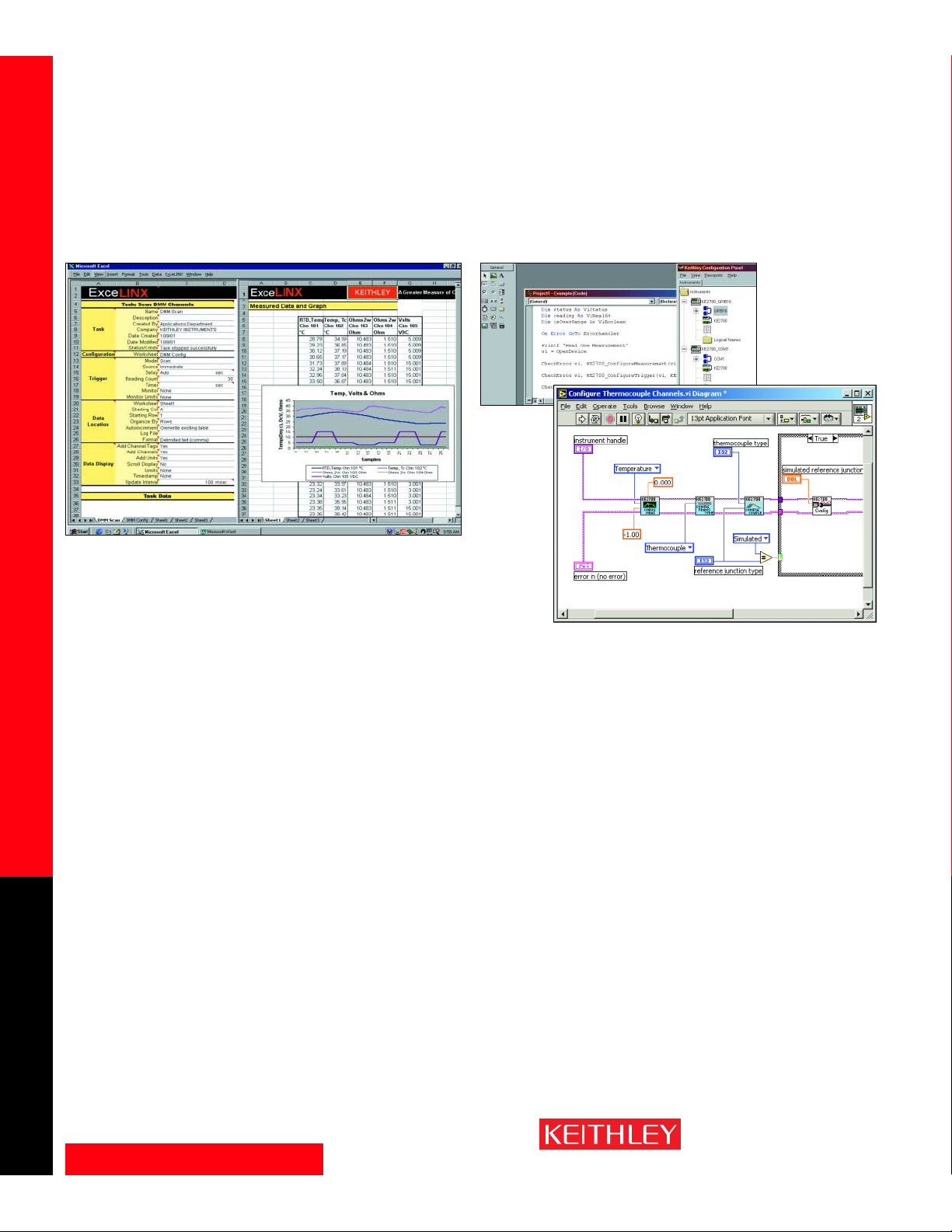
For advanced datalogging tasks, this powerful and economical add-in utility
for Microsoft
®
Excel makes it simple to acquire data from the Integra Series
instrument directly into Excel, then employ Excel’s graphic, charting, and
analysis capabilities to turn that data into useful information. No programming is required—a few mouse clicks are all it takes to configure channels,
set parameters, configure triggers, and scan lists. ExceLINX-1A can control up
to three Integra Series instruments for up to 600 channels of data acquisition.
Sold separately.
ExceLINX-1A
Datalogging/Data Acquisition Software Custom Application Development
with VISA Based IVI Driver
For building custom applications, programmers can take advantage of the
VISA based Integra series IVI driver designed for use with software development environments like Visual Basic, Visual C/C++, LabVIEW, LabWindows/
CVI, and TestPoint. The VISA (Virtual Instrument Software Architecture) layer
of the driver allows the programmer to quickly reconfigure the communication bus between the PC and the instruments without changing a single line of
source code. This means that changing GPIB control board vendors or switching the communication bus between GPIB, RS-232, and Ethernet requires no
rework of a custom application program. The IVI (Interchangeable Virtual
Instrument) layer of the driver provides a simplified command interface that is
common to the entire Integra Series product family. The driver also includes a
large set of examples for reference during software design.
Page 19
www.keithley.com
1.888.KEITHLEY (U.S. only)
A GREATER MEASURE OF CONFIDENCE
Integra Series Specifications
SWITCH/MEASURE SYSTEMS
19
Integra Series Multimeter/Switch Systems
Specifications are subject to change without notice.
Download the latest specs from www.keithley.com.
Page 20

www.keithley.com
1.888.KEITHLEY (U.S. only)
A GREATER MEASURE OF CONFIDENCE
Integra Series Specifications
SWITCH/MEASURE SYSTEMS
20
Integra Series Multimeter/Switch Systems
Mainframes
DC CHARACTERISTICS
1
CONDITIONS: MED (1 PLC)2or 10 PLC or MED (1 PLC) with Digital Filter of 10
INPUT
TEST RESISTANCE
ACCURACY: ±(ppm of reading + ppm of range)
CURRENT ±5% OR OPEN CKT.
(ppm = parts per million) (e.g., 10ppm = 0.
TEMPERATURE
OR BURDEN VOLTAGE
3
24 Hour
4
90 Day 1 Year COEFFICIENT
FUNCTION RANGE RESOLUTION VOLTAGE 2700/2701 2750 23°C±1° 23°C±5° 23°C±5° 0°–18°C & 28°–50°C
Voltage
11
100.0000 mV 0.1 µV >10 GΩ >10 GΩ 15 + 30 25 + 35 30 + 35 (1 + 5)/°C
1.000000 V 1.0 µV >10 GΩ >10 GΩ 15 + 6 25 + 7 30 + 7 (1 + 1)/°C
10.00000 V 10 µV >10 GΩ >10 GΩ 10 + 4 20 + 5 30 + 5 (1 + 1)/°C
100.0000 V 100 µV 10 MΩ ±1% 10MΩ ±1% 15 + 6 35 + 9 45 + 9 (5 + 1)/°C
1000.000 V
5
1mV 10MΩ ±1% 10MΩ ±1% 20 + 6 35 + 9 50 + 9 (5 + 1)/°C
Resistance
6, 8
1.000000 Ω
24
1µΩ 10 mA 5.9 V 80 + 40 80 + 40 100 + 40 (8 + 1)/°C
10.00000 Ω
24
10 µΩ 10 mA 5.9 V 20 + 20 80 + 20 100 + 20 (8 + 1)/°C
100.0000 Ω 100 µΩ 1mA 6.9 V 12.2 V 20 + 20 80 + 20 100 + 20 (8 + 1)/°C
1.000000 kΩ 1mΩ 1mA 6.9 V 12.2 V 20 + 6 80 + 6 100 + 6 (8 + 1)/°C
10.00000 kΩ 10 mΩ 100 µA 6.9 V 6.8 V 20 + 6 80 + 6 100 + 6 (8 + 1)/°C
100.0000 kΩ 100 mΩ 10 µA 12.8 V 12.8 V 20 + 6 80 + 10 100 + 10 (8 + 1)/°C
1.000000 MΩ
23
1.0 Ω 10 µA 12.8 V 12.8 V 20 + 6 80 + 10 100 + 10 (8 + 1)/°C
10.00000 MΩ
7, 23
10 Ω 0.7 µA // 10M Ω 7.0 V 7.0 V 150 + 6 200 + 10 400 + 10 (70 + 1)/°C
100.0000 MΩ
7, 23
100 Ω 0.7 µA // 10M Ω 7.0 V 7.0 V 800 + 30 2000 + 30 2000 + 30 (385 + 1)/°C
Dry Circuit 1.000000 Ω 1µΩ 10 mA 20 mV 80 + 40 80 + 40 100 + 40 (8 + 1)/°C
Resistance
21, 24
10.00000 Ω 10 µΩ 1mA20mV 25 + 40 80 + 40 100 + 40 (8 + 1)/°C
100.0000 Ω 100 µΩ 100 µA 20 mV 25 + 40 90 + 40 140 + 40 (8 + 1)/°C
1.000000 kΩ 1mΩ 10 µ A 20 mV 25 + 90 180 + 90 400 + 90 (8 + 1)/°C
Continuity (2W) 1.000 kΩ 100 mΩ 1mA 6.9 V 12.2 V 40 + 100 100 + 100 100 + 100 (8 + 1)/°C
Current 20.00000 mA 10 nA < 0.2 V 60 + 30 300 + 80 500 + 80 (50 + 5)/°C
100.0000 mA 100 nA < 0.1 V 100 + 300 300 + 800 500 + 800 (50 + 50)/°C
1.000000 A 1.0 µA < 0.5 V
9
200 + 30 500 + 80 800 + 80 (50 + 5)/°C
3.000000 A 10 µA < 1.5 V
9
1000 + 15 1200 + 40 1200 + 40 (50 + 5)/°C
Channel (Ratio)
10
Ratio Accuracy = Accuracy of selected Channel Range + Accuracy of Paired Channel Range
Channel (Average)
10
Average Accuracy = Accuracy of selected Channel Range + Accuracy of Paired Channel Range
TEMPERATURE
19
(Displayed in °C, °F, or K. Exclusive of probe errors.)
Thermocouples (Accuracy based on ITS-90.)
90 Day/1 Year (23°C ± 5°C)
Relative to Using Temperature
Simulated 7710 Using Coefficient
Reference Module 77XX 0°–18°C &
Type Range Resolution Junction (preliminary) Module 28°–50°C
J –200 to +760 °C 0.001 °C 0.2°C 0.7°C 1.0°C 0.03°C/°C
K –200 to +1372°C 0.001 °C 0.2°C 0.7°C 1.0°C 0.03°C/°C
N –200 to +1300°C 0.001 °C 0.2°C 0.7°C 1.0°C 0.03°C/°C
T –200 to +400°C 0.001 °C 0.2°C 0.7°C 1.0°C 0.03°C/°C
E –200 to +1000°C 0.001 °C 0.2°C 0.7°C 1.0°C 0.03°C/°C
R0 to +1768°C 0.1 °C 0.6°C 1.5°C 1.8°C 0.03°C/°C
S0 to +1768°C 0.1 °C 0.6°C 1.5°C 1.8°C 0.03°C/°C
B +350 to +1820°C 0.1 °C 0.6°C 1.5°C 1.8°C 0.03°C/°C
4-Wire RTD:
(100Ω platinum [PT100], D100, F100, PT385, PT3916, or user type. Offset compensation On)
–200° to 630°C 0.01 °C 0.06°C 0.003°C/°C
Thermistor: (2.2kΩ, 5kΩ, and 10kΩ)
20
–80° to 150°C 0.01 °C 0.08°C 0.002°C/°C
DC SYSTEM SPEEDS
15,18
2700/2750 2701
RANGE CHANGES (excludes 4WΩ)
16
: 50/s (42/s) 50/s (42/s)
FUNCTION CHANGES
16
: 50/s (42/s) 50/s (42/s)
AUTORANGE TIME
16
: <30 ms <30 ms
ASCII READINGS TO RS-232 (19.2k BAUD): 55/s 300/s
MAX. EXTERNAL TRIGGER RATE: 375/s 2000/s
DC MEASUREMENT SPEEDS
15
Single Channel, 60Hz (50Hz) Operation
FUNCTION DIGITS READINGS/s PLCs
DCV, DCI, Ω (<10M), 6.5
12,16
5(4) 10
Thermocouple, 6.5
16
35 (28) 1
Thermistor 6.5
12,16
45 (36) 1
5.5
12,16
150 (120) 0.1
5.5
16, 17
300 (240) 0.1
5.5
17
500 (400) 0.1
2701 and 2750 only 4.5
17
2500 (2000) 0.01
2701 only 3.5 3500 (2800) 0.002
4WΩ (<10M) 6.5
16
1.4 (1.1) 10
6.5
16
15 (12) 1
5.5
17
33 (25) 0.1
4WΩ OComp, RTD
22
6.5
16
0.9 (0.7) 10
6.5
16
8 (6.4) 1
5.5
16, 17
18 (14.4) 0.1
Channel (Ratio), 6.5
16
2.5 (2) 10
Channel (AVG) 6.5
16
15 (12) 1
5.5
17
25 (20) 0.1
Multiple Channels, Into Memory
18
Channels/s
2700 2701 2750
7710 Scanning DCV 180/s 500/s 230/s
7710 Scanning DCV with Limits or Time Stamp On 170/s 500/s 230/s
7710 Scanning DCV alternating 2WΩ 45/s 115/s 60/s
Multiple Channels, Into and Out of Memory to GPIB
16, 18
or Ethernet Channels/s
2700 2701 2750
7702 Scanning DCV 65/s 75/s 65/s
7700 and 7708 Scanning Temperature (T/C) 50/s 50/s 50/s
7710 Scanning DCV 145/s 440/s 210/s
7710 Scanning DCV with Limits or Time Stamp On 145/s 440/s 210/s
7710 Scanning DCV alternating 2WΩ 40/s 115/s 55/s
Page 21

www.keithley.com
1.888.KEITHLEY (U.S. only)
A GREATER MEASURE OF CONFIDENCE
Integra Series Specifications
SWITCH/MEASURE SYSTEMS
21
Integra Series Multimeter/Switch Systems
Mainframes
DC NOTES
1. 20% overrange except on 1000V and 3A.
2. Add the following to “ppm of range” uncertainty; 100mV 15ppm; 1V and 100V 2ppm; for Model 2750 1Ω and Dry Circuit
Ω 40ppm; 10→1MΩ 2ppm, for Models 2700/2701 100Ω 30ppm, 20mA and 1A 10ppm, 100mA 40ppm.
3. ±2% (measured with 10MΩ input resistance DMM, >10GΩ DMM on 10MΩ and 100MΩ ranges). For Dry Circuit Ω, ±25%
with Input HI connected to Sense HI; with Sense HI disconnected add 30mV.
4. Relative to calibration accuracy.
5. For signal levels >500V, add 0.02ppm/V uncertainty for portion exceeding 500V.
6. Specifications are for 4-wire Ω, 1Ω, 10Ω, and 100Ω with offset compensation on. With 77XX plug-in modules, LSYNC on.
With offset compensation on, OPEN CKT. VOLTAGE is 12.8V. For 2-wire Ω add 1.5Ω to “ppm of range” uncertainty. 1Ω
range is 4-wire only.
7. Must have 10% matching of lead resistance in Input HI and LO.
8. Add the following to “ppm of reading” uncertainty when using plug in modules:
10 kΩ 100 kΩ 1 MΩ 10 MΩ 100 MΩ
All Modules: 220 ppm 2200 ppm
7701, 7703, 7707, 7709 Modules: 10 ppm 100 ppm 1000 ppm 1% 10%
7706, 7708, 7710 Modules: 5 ppm 50 ppm 500 ppm 5000 ppm 5%
7710 Module 23°C ±5°C: 11 ppm 110 ppm 1100 ppm 1.1% 11%
9. Add 1.5V when used with plug in modules.
10. For RATIO, DCV only. For AVERAGE, DCV and Thermocouples only. Available with plug in modules only.
11. Add 6µV to “of range” uncertainty when using Models 7701, 7703, and 7707, and 3µV for Models 7706 and 7709.
12. Auto zero off.
13. For LSYNC On, line frequency ±0.1 %. For LSYNC Off, use 60dB for ≥ 1PLC.
14. For 1kΩunbalance in LO lead. AC CMRR is 70dB.
15. Speeds are for 60Hz (50Hz) operation using factory defaults operating conditions (*RST). Autorange off, Display off, Limits
off, Trigger delay = 0.
16. Speeds include measurements and binary data transfer out the GPIB or ASCII data transfer for Ethernet and RS-232 (reading element only).
17. Sample count = 1000, auto zero off (into memory buffer).
18. Auto zero off, NPLC = 0.01 (Models 2700 and 2750), NPLC = 0.002 (Model 2701).
19. Additional Uncertainty: Plug-In Modules
Front Terminals 7709 7701, 7703, 7707 7700, 7708, 7706
Simulated Simulated Simulated 7710 Using Using
Type Range Ref. Junction Ref. Junction Ref. Junction CJC CJC
J –200 to 0°C 0.1 0.1 0.3 0.8 1.6
K –200 to 0°C 0.2 0.2 0.4 0.8 1.6
N –200 to 0°C 0.3 0.3 0.6 0.8 1.6
T –200 to 0°C 0.2 0.1 0.4 0.8 1.6
E –200 to 0°C – 0.1 0.3 0.8 1.6
R0 to +400°C 0.4 0.6 1.2 0.5 1.0
S0 to +400°C 0.4 0.6 1.2 0.5 1.0
B +350 to +1100°C 0.8 0.3 1.7 0.5 1.0
20. For lead resistance >0Ω, add the following uncertainty/Ωfor measurement temperatures of:
70°–100°C 100°–150°C
2.2 kΩ (44004) 0.22°C 1.11°C
5.0 kΩ (44007) 0.10°C 0.46°C
10 kΩ (44006) 0.04°C 0.19°C
21. For 4-wire Ωonly, offset compensation on, LSYNC on.
22. For Dry Circuit 1kΩrange, 2 readings/s max.
23. For 2750 Front Inputs, add the following to Temperature Coefficient “ppm of reading” uncertainty: 1MΩ 25ppm, 10MΩ
250ppm, 100MΩ 2500ppm. Operating environment specified for 0°C to 50°C and 50% RH at 35°C.
24. Model 2750 only.
25. Front panel resolution is limited to 0.1Ω.
AC SPECIFICATIONS
1
Accuracy: ±(% of reading + % of range), 23°C ± 5°C
Calibration 3 Hz– 10 Hz– 20 kHz– 50 kHz– 100 kHz–
Function Range Resolution Cycle 10 Hz 20 kHz 50 kHz 100 kHz 300 kHz
Voltage
2
100.0000 mV 0.1 µV 90 Days 0.35 + 0.03 0.05 + 0.03 0.11 + 0.05 0.6 + 0.08 4.0 + 0.5
1.000000 V 1.0 µV (all ranges)
10.00000 V 10 µV 1 Year 0.35 + 0.03 0.06 + 0.03 0.12 + 0.05 0.6 + 0.08 4.0 + 0.5
100.0000 V 100 µV (all ranges)
750.000 V 1.0 µV
(Temp. Coeff.)/°C30.035 + .003 0.005 + .003 0.006 + .005 0.01 + .006 0.03 + .01
3 Hz–10 Hz 10 Hz–3 kHz 3 kHz–5 kHz
Current
2
1.000000 A 1.0 µA 90 Day/1 Yr. 0.30 + 0.04 0.10 + 0.04 0.14 + 0.04
3.00000 A
14
10 µA 0.35 + 0.06 0.16 + 0.06 0.18 + 0.06
(Temp. Coeff.)/°C30.035 + 0.006 0.015 + 0.006
(3 Hz–500 kHz) (333 ms–2 µs)
Frequency
4
100 mV 0.333 ppm 90 Day/ 1 Yr. 100 ppm + 0.333 ppm (SLOW, 1s gate)
and Period to 3.33 ppm 100 ppm + 3.33 ppm (MED, 100ms gate)
750 V 33.3 ppm 100 ppm + 33.3 ppm (FAST, 10ms gate)
DC SPEED vs. NOISE REJECTION
RMS Noise
10V Range
Rate Filter Readings/s12Digits 2700,2750 2701 NMRR CMRR
14
10 50 0.1 (0.08) 6.5 < 1.2 µV < 2.5 µV 110 dB13140 dB
1 Off 15 (12) 6.5 < 4 µV < 6 µV 90 dB
13
140 dB
0.1 Off 500 (400) 5.5 < 22 µV < 40 µV — 80 dB
0.01 Off 2500 (2000) 4.5 < 150 µV < 300 µV — 80 dB
0.002 Off 3500 (2800) 3.5 — < 1 mV — 60 dB
DC MEASUREMENT CHARACTERISTICS
DC VOLTS
A-D LINEARITY: 2.0 ppm of reading + 1.0 ppm of range.
INPUT IMPEDANCE:
100mV–10V Ranges: Selectable >10GΩ // with <400pF or 10MΩ ±1%.
100V, 1000V Ranges: 10MΩ ±1%.
Dry Circuit: 100kΩ ±1% // <1µF.
EARTH ISOLATION: 500V peak, >10GΩ and <300pF any terminal to chassis.
INPUT BIAS CURRENT: <75pA at 23°C.
COMMON MODE CURRENT: <500nApp at 50Hz or 60Hz.
AUTOZERO ERROR: Add ±(2ppm of range error + 5µV) for < 10 minutes and ±1°C.
INPUT PROTECTION: 1000V, all ranges. 300V with plug in modules.
RESISTANCE
MAXIMUM 4WΩ LEAD RESISTANCE: 80% of range per lead (Dry Ckt mode). 5Ωper
lead for 1Ω range; 10% of range per lead for 10Ω, 100Ω, and 1kΩ ranges; 1kΩ
per lead for all other ranges.
OFFSET COMPENSATION: Selectable on 4WΩ, 1Ω, 10Ω, 100Ω, 1kΩ, and 10kΩ
ranges.
CONTINUITY THRESHOLD: Adjustable 1 to 1000 Ω
INPUT PROTECTION: 1000V, all Source Inputs, 350V Sense Inputs. 300V with plug-in
modules.
DC CURRENT
SHUNT RESISTORS: 100mA–3A, 0.1Ω. 20mA, 5Ω.
INPUT PROTECTION: 3A, 250V fuse.
THERMOCOUPLES
CONVERSION: ITS-90.
REFERENCE JUNCTION: Internal, External, or Simulated (Fixed).
OPEN CIRCUIT CHECK: Selectable per channel. Open >11.4kΩ ±200Ω.
Page 22

www.keithley.com
1.888.KEITHLEY (U.S. only)
A GREATER MEASURE OF CONFIDENCE
Integra Series Specifications
SWITCH/MEASURE SYSTEMS
22
Integra Series Multimeter/Switch Systems
Mainframes
ADDITIONAL UNCERTAINTY ±(% OF READING)
Low Frequency Uncertainty MED FAST
20 Hz – 30 Hz 0.3 —
30 Hz – 50 Hz 0 —
50 Hz – 100 Hz 0 1.0
100 Hz – 200 Hz 0 0.18
200 Hz – 300 Hz 0 0.10
>300 Hz 0 0
CREST FACTOR:
5
1–2 2–3 3–4 4–5
Additional Uncertainty: 0.05 0.15 0.30 0.40
Max. Fundamental Freq.: 50kHz 50kHz 3kHz 1kHz
Maximum Crest Factor: 5 at full-scale.
AC MEASUREMENT CHARACTERISTICS
AC VOLTS
MEASUREMENT METHOD: AC-coupled, True RMS.
INPUT IMPEDANCE: 1MΩ±2% // by <100pF.
INPUT PROTECTION: 1000Vp or 400VDC. 300Vrms with plug in modules.
AC CURRENT
MEASUREMENT METHOD: AC-coupled, True RMS.
SHUNT RESISTANCE: 0.1Ω.
BURDEN VOLTAGE: 1A <0.5Vrms, 3A <1.5Vrms. Add 1.5Vrms when used with plug
in modules.
INPUT PROTECTION: 3A, 250V fuse.
FREQUENCY AND PERIOD
MEASUREMENT METHOD: Reciprocal counting technique.
GATE TIME: SLOW 1s, MED 100ms, and FAST 10ms.
AC GENERAL
AC CMRR6: 70dB.
VOLT HERTZ PRODUCT: <= 8 × 10
7
.
AC MEASUREMENT SPEEDS
7, 13
Single Channel, 60Hz (50Hz) Operation
Function Digits Readings/s Rate Bandwidth
ACV, ACI 6.5 2s/Reading SLOW 3 Hz–300 kHz
6.5 4.8 (4) MED 30 Hz–300 kHz
6.5
9
40 (32) FAST 300 Hz–300 kHz
Frequency, 6.5 1 (1) SLOW 3 Hz–300 kHz
Period 5.5 9 (9) MED 30 Hz–300 kHz
4.5 35 (35) FAST 300 Hz–300 kHz
4.5
10
65 (65) FAST 300 Hz–300 kHz
Multiple Channel
7710 SCANNING ACV
10, 11
: 500/s.
7710 SCANNING ACV WITH AUTO DELAY ON: 2s/reading.
AC SYSTEM SPEEDS
7, 9, 11
2700/2750 2701
AC System Speed: (19.2k) (115.2K)
Range Changes:
12
4/s (3/s) 4/s (3/s)
Function Changes:
12
4/s (3/s) 4/s (3/s)
Autorange Time: < 3s < 3s
ASCII Readings to RS-232 (19.2k baud): 50/s 300/s
Max. External Trigger Rate: 250/s 2000/s
AC NOTES
1. 20 % overrange except on 750V and 3A.
2. Specification are for SLOW mode and sine wave inputs >5% of range. SLOW and MED are multi-sample A/D conversions.
FAST is DETector:BANDwidth 300 with nPLC = 1.0.
3. Applies to 0°–18°C and 28°–50°C.
4. For square wave inputs >10% of ACV range, except 100mV range. 100mV range frequency must be >10Hz if input is <20mV.
5. Applies to non-sine waves >5Hz.
6. For 1kΩ unbalance in LO lead.
7. Speeds are for 60Hz (50Hz) operation using factory defaults operating conditions (*RST). Autorange off, Display off, Limits
off, Trigger delay=0..
8. For ACV inputs at frequencies of 50 or 60Hz (±10%), add the following to “% of Range” uncertainty: 100mV 0.25%, 1V
0.05%, 10V 0.13%, 100V 0.03%, 750V 0.015 (Model 2701 only)..
9. Auto Zero off.
10. Sample count = 1024.
11. DETector:BANDwidth 300 with nPLC = 0.006 (2701 only).
12. Maximum useful limit with trigger delay = 175ms.
13. Includes measurement and binar y data transfer out GPIB or ASCII data transfer for Ethernet and RS-232 (Reading Element only).
GENERAL SPECIFICATIONS:
EXPANSION SLOTS: 2 (2700, 2701), 5 (2750).
POWER SUPPLY: 100V / 120V / 220V / 240V ±10%.
LINE FREQUENCY: 45Hz to 66Hz and 360Hz to 440Hz, automatically sensed at power-up.
POWER CONSUMPTION: 28VA (2700), 80VA (2701, 2750).
OPERATING ENVIRONMENT: Specified for 0°C to 50°C. Specified to 80% RH at 35°C.
STORAGE ENVIRONMENT: –40°C to 70°C.
BATTERY: Lithium battery-backed memory, 3 years @ 23°C (Models 2700, 2750) Lithium Ion batter y-backed
memory, 30 days of buffer storage @ 23°C and >4 hours charge time. Battery lifetime: >3 years @ 23°C,
>1.5 years @ 50°C (Model 2701)
WARRANTY: 3 years excludes battery.
EMC: Conforms to European Union Directive 89/336/EEC EN61326-1.
SAFETY: Conforms to European Union Directive 73/23/EEC EN61010-1, CAT I.
VIBRATION: MIL-PRF-28800F Class 3, Random.
WARM-UP: 2 hours to rated accuracy.
DIMENSIONS:
Rack Mounting: 89mm high × 213mm wide (2700, 2701) or 485mm wide (2750) × 370mm deep (3.5 in ×
8.375 in or 19 in × 14.563 in).
Bench Configuration (with handle and feet): 104mm high × 238mm wide (2700, 2701) or 485mm wide
(2750) × 370mm deep (4.125 in × 9.375 in (2700, 2701) or 19 in (2750) × 14.563 in).
SHIPPING WEIGHT: 6.5kg (14 lbs.) (2700, 2701) or 13kg (28 lbs.) (2750).
DIGITAL I/O: 2 inputs, 1 for triggering and 1 for hardware interlock.
5 outputs, 4 for Reading Limits and 1 for Master Limit. Outputs are TTL compatible or can sink 250mA,
diode clamped to 40V.
TRIGGERING AND MEMORY:
Window Filter Sensitivity: 0.01%, 0.1 %, 1%, 10%, or Full-scale of range (none).
Reading Hold Sensitivity: 0.01%, 0.1 %, 1%, or 10% of reading.
Trigger Delay: 0 to 99 hrs (1ms step size).
External Trigger Delay: <2ms (2700), <1ms (2701, 2750).
External Trigger Jitter: <1ms (2700), <500µs (2701), <500µs (2750).
Memory Size: 55,000 readings (2700), 450,000 readings (2701), 110,000 readings (2750).
MATH FUNCTIONS: Rel, Min/Max/Average/Std Dev/Peak-to-Peak (of stored reading), Limit Test, %, 1/x, and
mX+b with user defined units displayed.
REMOTE INTERFACE:
GPIB (IEEE-488.2) (2700, 2750) and RS-232C.
Ethernet TCP/IP (10bT and 100bT) (2701)
SCPI (Standard Commands for Programmable Instruments)
LabVIEW Drivers
ACCESSORIES SUPPLIED: Model 1751 Safety Test Leads, Product Informtion CD-ROM. (Model 2701 only:
Getting Started Foldout, 3m Ethernet crossover cable, software CD-ROM with IVI/VISA drivers for VB,
VC/C++, LabVIEW, TestPoint, and LabWindows/CVI, plus free runtime start-up software.)
ACCESSORIES AVAILABLE:
4288-7Rack Mount Rear Support Kit (2750)
77XX-904A Module Manual
77XXModules
Extended Warranty
ExceLINX-1A (Excel add-in datalogger software)
TestPoint™ Software Development Package
FOR MODEL 2701:
Ethernet: RJ-45 connector, TCP/IP, 10bT and 100bTx autosensed.
IP Configuration: Static or DHCP.
Password Protection: 11 Characters.
Software: Windows 98, NT, 2000, ME, and XP compatible. Internet Explorer 5.0 or higher required. Web
page server by 2701.
Page 23
www.keithley.com
1.888.KEITHLEY (U.S. only)
A GREATER MEASURE OF CONFIDENCE
Model 7700 Specifications
SWITCH/MEASURE SYSTEMS
23
Integra Series Multimeter/Switch Systems
Modules
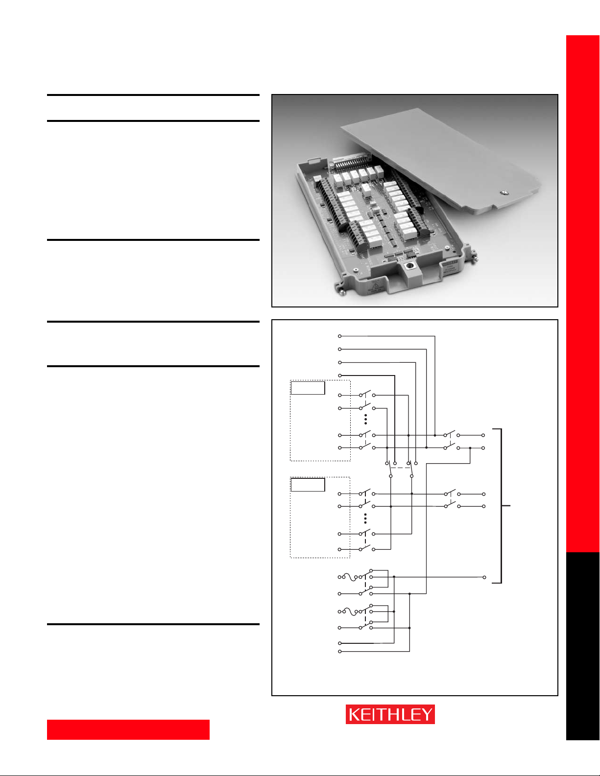
7700 20-CHANNEL DIFFERENTIAL MULTIPLEXER
W/AUTOMATIC CJC
FEATURES
• 20 channels for general-purpose measurements, plus two channels to measure
current.
• 2- or 4-wire measurement.
•Oversize screw terminal connection blocks are standard for easier connections.
•Automatic CJC sensors on the scanner card mean there are no other accessories are
required to make thermocouple temperature measurements.
• Configurable as two independent banks of multiplexers.
• 300V, 1A capacity for voltage channels; 60W, 125VA.
• 3A capacity for current channels.
• Relay closures stored in on-board memory.
GENERAL
20 CHANNELS: 20 channels of 2-pole relay input. All channels configurable to 4-pole.
2 CHANNELS: 2 channels of current only input.
RELAY TYPE: Latching electromechanical.
ACTUATION TIME: <3ms.
FIRMWARE: Specified for Model 2700 rev. A01, 2701 rev. A01, and 2750 rev. A01 or
higher.
CAPABILITIES
CHANNELS 1-20: Multiplex one of 20 2-pole or one of 10 4-pole signals into DMM.
CHANNELS 21-22: Multiplex one of 2 2-pole current signals into DMM.
INPUTS
MAXIMUM SIGNAL LEVEL:
Channels (1-20): 300V DC or 300V rms (425V peak) for AC waveforms, 1A
switched, 60W, 125VA maximum.
Channels (21-22): 60V DC or 30V rms, 3A switched, 60W, 125VA maximum.
CONTACT LIFE (typ.): >10
5
operations at max signal level.
>10
8
operations cold switching.
CONTACT RESISTANCE: <1Ω at end of contact life.
CONTACT POTENTIAL: <±500nV typical per contact, 1µV max.
<±500nV typical per contact pair, 1µV max.
OFFSET CURRENT: <100pA.
CONNECTOR TYPE: Screw terminal, #20 AWG wire size.
ISOLATION BETWEEN ANY TWO TERMINALS: >10
10
Ω, <100pF.
ISOLATION BETWEEN ANY TERMINAL AND EARTH: >10
9
Ω, <200pF.
INSERTION LOSS (50Ω Source, 50Ω Load):
w/Internal DMM w/o Internal DMM*
<0.1 dB: 1 MHz 1 MHz
<3 dB: 2 MHz 50 MHz
CROSSTALK (50Ω Load): w/Internal DMM w/o Internal DMM*
10 MHz: <–40 dB <–40 dB
25 MHz: ** <–25 dB
COMMON MODE VOLTAGE: 300V or 300V rms (425V peak) for AC waveforms
between any terminal and chassis.
TEMPERATURE ACCURACY USING INTERNAL CJC: 1.0°C (see mainframe specifica-
tion for details).
* Channels 24 and 25 are open. Refer to ROUTe:MULTiple command in 27XX User Manual.
** Not valid.
ENVIRONMENTAL:
OPERATING ENVIRONMENT: Specified for 0°C to 50°C.
Specified to 80% R.H. at 35°C.
STORAGE ENVIRONMENT: –25°C to 65°C.
WEIGHT: 0.45kg (1 lb).
ACCESSORY AVAILABLE: Model 7401 Type K Thermocouple Wire, 30.5m (100 ft).
a
Card Input
Card Sense
Cold junction
Ref x3
Channel 1
(Channels 2–9)
Channel 10
Cold junction
Ref x3
Channel 11
(Channels 12–19)
Channel 20
Channel 21
Channel 22
AMPS
Card
HI
LO
HI
LO
HI
LO
HI
LO
HI
LO
HI
LO
HI
LO
HI
LO
LO
Channel 23
2-Pole (Open)
4-Pole (Closed)
(see Note)
3A
3A
Channel 25
(see Note)
Backplane
isolation
Channel 24
(see Note)
Backplane
isolation
NOTE Channels 23–25 in this schematic
refer to the designations used for
control and not actual available channels.
For more information, refer to the
ROUTe:MULTiple command section
in the Model 2700, 2701, or 2750 User’s Manu
Channels 24 and 25 can be individually
controlled using ROUTe:MULTiple if the
module is not to be connected to the
internal DMM.
AMPS
HI
Input
LO
HI
Sense
LO
To Model 2700,
2701, or 2750
Backplane
Page 24
www.keithley.com
1.888.KEITHLEY (U.S. only)
A GREATER MEASURE OF CONFIDENCE
Model 7701 Specifications
SWITCH/MEASURE SYSTEMS
24
Integra Series Multimeter/Switch Systems
Modules
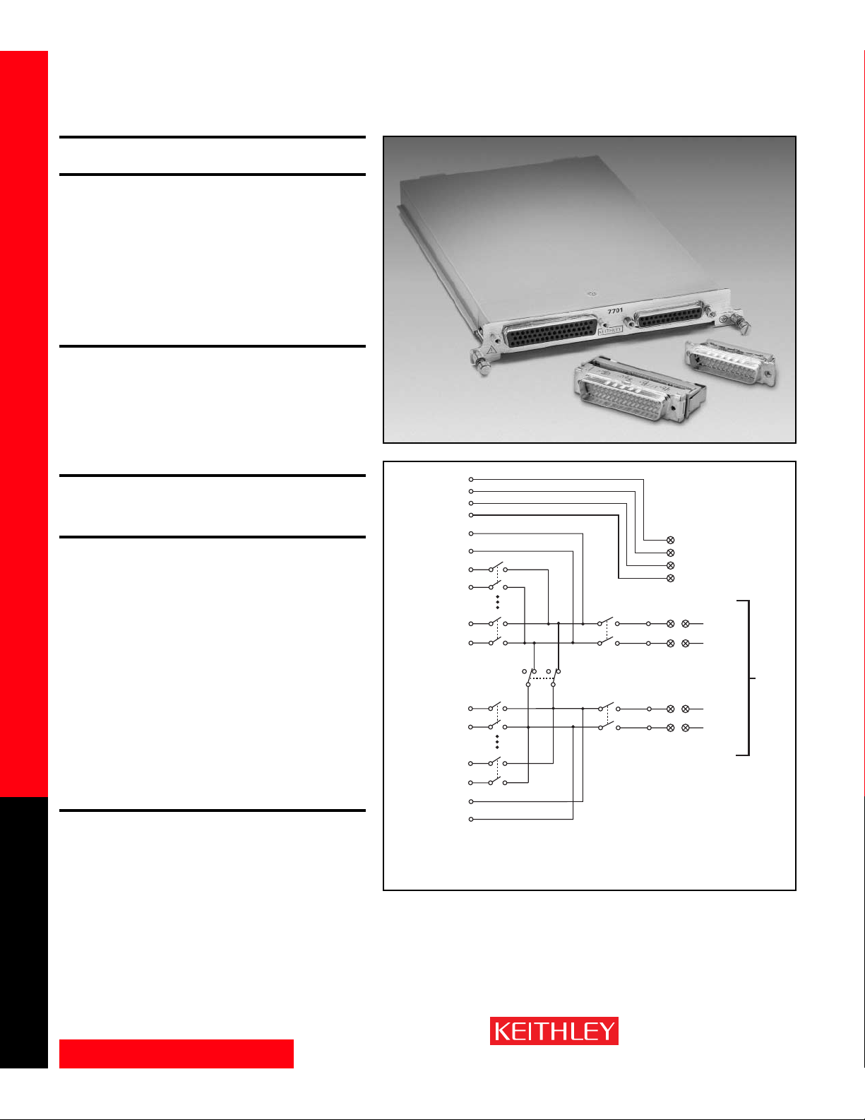
7701 LOW-VOLTAGE 32-CHANNEL
DIFFERENTIAL MULTIPLEXER
FEATURES
• Configurable for 32 channels of differential measurements, with up to 16 channels
of 4-pole measurements.
• Configurable for 32 channels of common-side 4-wire ohms.
•Configurable as two independent banks of multiplexers.
•Two female D-shell connectors are standard for secure hook-up and
quick teardown.
• 150V, 1A capacity for voltage channels; 60W, 125VA.
•Two mating IDC connectors for ribbon cable (Model 7790) are supplied.
• Relay closures stored in on-board memory.
• Screw terminal jumpers allow user-configurable DMM connections.
GENERAL
32 CHANNELS: 32 channels of 2-pole relay input. All channels configurable to 4-pole.
RELAY TYPE: Latching electromechanical.
ACTUATION TIME: <3ms.
FIRMWARE: Specified for Model 2700 rev. B03, Model 2701 rev. A01, and Model 2750
rev. A01 or higher.
DMM CONNECTIONS: Screw terminals provide internal DMM connections to chan-
nels 34 and 35 and connections to external wiring access.
CAPABILITIES
CHANNELS 1–32: Multiplex one of 32 2-pole or one of 16 4-pole signals into DMM.
Configuration supports dual 1×16 independent multiplexers.
INPUTS
MAXIMUM SIGNAL LEVEL: Any channel to Any Channel (1–32): 150V DC or
150Vrms (212V peak) for AC waveforms, 1A switched, 60W, 125VA maximum.
SAFETY: Conforms to European Union Directive 73/23/EEC EN61010-1, CAT I.
CONTACT LIFE (typ): >10
5
operations at max signal level.
>10
8
operations cold switching.
CONTACT RESISTANCE: <1Ω any path and additional 1Ω at end of contact life.
CONTACT POTENTIAL: <6µV per contact pair.
OFFSET CURRENT: <100pA.
CONNECTOR TYPE: 50-pin female D-shell, Channels 1–24.
25-pin female D-shell, Channels 25–32.
Supplied with male IDC ribbon cable connectors.
ISOLATION BETWEEN ANY TWO TERMINALS: >10
9
Ω, <200pF.
ISOLATION BETWEEN ANY TERMINAL AND EARTH: >10
9
Ω, <400pF.
CROSS TALK (1MHz, 50ΩLoad): <–35dB.
INSERTION LOSS (50Ω Source, 50Ω Load): <0.35dB below 1MHz.
<3dB below 2MHz.
COMMON MODE VOLTAGE: 300VDC or 300Vrms (425V peak) for AC waveforms
between any terminal and chassis.
ENVIRONMENTAL:
OPERATING ENVIRONMENT: Specified for 0°C to 50°C.
Specified to 50% R.H. at 35°C.
STORAGE ENVIRONMENT: –25°C to 65°C.
WEIGHT: <0.52kg (1.16 lb).
ACCESSORIES AVAILABLE:
Model 7789 50/25 Pin Male D-Shell Solder Cup Connectors
Model 7790 50/50/25 Pin Female/Male D-Shell IDC Connectors
Model 7705-MTC-2 50 Pin Male to Female DSUB Cable, 2m (6.6 ft).
Model 7707-MTC-2 25 Pin Male to Female DSUB Cable, 2m (6.6 ft).
See page 43 for common-side 4-wire ohms configuration example.
External
Wiring Access
Multiplexer 1
Channel 1
(Channels 2–15)
Channel 16
Channel 17
(Channels 18–31)
Channel 32
Multiplexer 2
HI
LO
HI
LO
HI
LO
Channel 33
2-Pole (Open)
4-Pole (Closed)
(see Note)
HI
LO
HI
LO
HI
LO
User
Configurable
Screw
Ter m inals
Channel 35
(see Note)
Backplane
Isolation
Channel 34
(see Note)
Backplane
Isolation
The Model 7701 is rated for low-voltage applications.
When connecting the 7701 to the internal DMM via
the screw terminals, all other modules in the
mainframe must be derated to 150VDC or 150Vrms
(212V peak) for AC waveforms.
NOTE Channels 33–35 in this schematic refer to the designations
used for control and not actual available channels.
For more information, refer to the ROUTE:MULT command
section in the Model 2700, 2701, or 2750 User’s Manual.
Screw
Ter m inals
HI
LO
Screw
Ter m inals
HI
LO
HI
DMM Input
LO
HI
DMM Sense
LO
To
Internal
DMM
Page 25
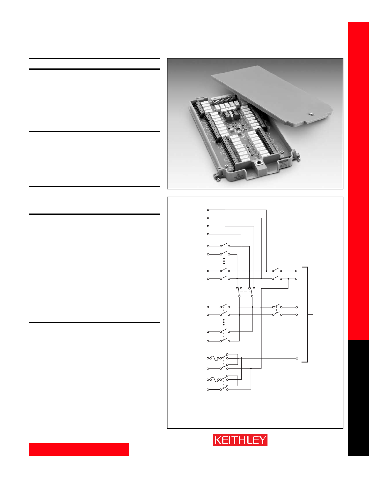
www.keithley.com
1.888.KEITHLEY (U.S. only)
A GREATER MEASURE OF CONFIDENCE
Model 7702 Specifications
SWITCH/MEASURE SYSTEMS
25
Integra Series Multimeter/Switch Systems
Modules
7702 40-CHANNEL DIFFERENTIAL MULTIPLEXER
FEATURES
• There are 40 channels for general-purpose measurement, plus 2 channels to
measure current.
• 2- or 4-wire measurement.
• Oversize screw terminal connection blocks are standard for easier connection.
• Configurable as two independent banks of multiplexers.
• 300V, 1A capacity for voltage channels; 60W, 125VA.
• 3A capacity for current channels.
• Relay closures stored in on-board memory.
GENERAL
40 CHANNELS: 40 channels of 2-pole relay input.
All channels configurable to 4-pole.
2 CHANNELS: 2 channels of current only input.
RELAY TYPE: Latching electromechanical.
ACTUATION TIME: <3ms.
FIRMWARE: Specified for Model 2700 rev. A01, 2701 rev. A01, and 2750 rev. A01
or higher.
CAPABILITIES
CHANNELS 1-40: Multiplex one of 40 2-pole or one of 20 4-pole signals into DMM.
CHANNELS 41-42: Multiplex one of 2 2-pole current signals into DMM.
INPUTS
MAXIMUM SIGNAL LEVEL:
Channels (1-40): 300V DC or rms, 1A switched, 60W, 125VA maximum.
Channels (41-42): 60V DC or 30V rms, 3A switched, 60W, 125VA maximum.
CONTACT LIFE (typ): >10
5
operations at max signal level.
>10
8
operations cold switching.
CONTACT RESISTANCE: <1Ω at end of contact life.
CONTACT POTENTIAL: <±500nV typical per contact, 1µV max.
<±500nV typical per contact pair, 1µV max.
OFFSET CURRENT: <100pA.
CONNECTOR TYPE: Screw terminal, #20 AWG wire size.
ISOLATION BETWEEN ANY TWO TERMINALS: >10
10
Ω, <100pF.
ISOLATION BETWEEN ANY TERMINAL AND EARTH: >10
9
Ω, <200pF.
CROSS TALK (10MHz, 50ΩLoad): <–40dB.
INSERTION LOSS (50Ω Source, 50Ω Load): <0.1dB below 1MHz.
<3dB below 2MHz.
COMMON MODE VOLTAGE: 300V between any terminal and chassis.
ENVIRONMENTAL
OPERATING ENVIRONMENT: Specified for 0°C to 50°C.
Specified to 80% R.H. at 35°C.
STORAGE ENVIRONMENT: –25°C to 65°C.
WEIGHT: 0.5kg (1.1 lb).
Card Input
Card Sense
Channel 1
(Channels 2–19)
Channel 20
Channel 21
(Channels 22–39)
Channel 40
Channel 41
Channel 42
HI
LO
HI
LO
HI
LO
HI
LO
HI
LO
HI
LO
HI
LO
HI
LO
Channel 43
2-Pole (Open)
4-Pole (Closed)
(see Note)
3A
3A
Channel 45
(see Note)
Backplane
isolation
Channel 44
(see Note)
Backplane
isolation
NOTE Channels 43–45 in this schematic
refer to the designations used for
control and not actual available channels.
For more information, refer to the
ROUTe:MULTiple command section
in the Model 2700, 2701, or 2750 User’s Manual.
Channels 44 and 45 can be individually
controlled using ROUTe:MULTiple if the
module is not to be connected to the
internal DMM.
AMPS
HI
Input
LO
HI
Sense
LO
To Model 2700,
2701, or 2750
Backplane
Page 26
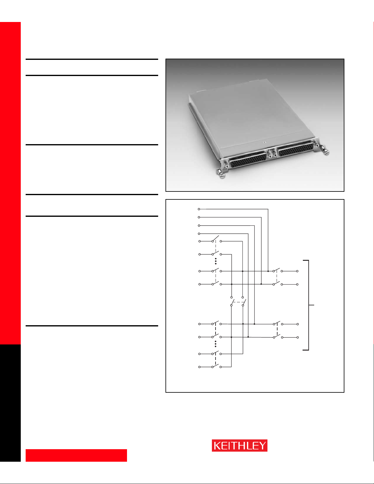
www.keithley.com
1.888.KEITHLEY (U.S. only)
A GREATER MEASURE OF CONFIDENCE
Model 7703 Specifications
SWITCH/MEASURE SYSTEMS
26
Integra Series Multimeter/Switch Systems
Modules
7703 32-CHANNEL HIGH SPEED DIFFERENTIAL
MULTIPLEXER
FEATURES
• There are 32 channels for general purpose measurement.
• Relay actuation time of less than 1ms for high-speed scanning.
•2 or 4 wire measurement.
•Two 50-pin female “D-sub” connectors are standard for secure hook-up and
quick teardown.
•Configurable as two independent banks of multiplexers.
• Reed relay based design with 300 volt, 500mA; 10VA.
•Two mating connector with solder cup (Model 7788) are supplied.
• Relay closures stored in on-board memory.
GENERAL
32 CHANNELS: 32 channels of 2-pole relay input.
All channels configurable to 4-pole.
RELAY TYPE: Reed.
ACTUATION TIME: <1ms.
FIRMWARE: Specified for Model 2700 rev. A01, 2701 rev. A01, and 2750 rev. A01
or higher.
CAPABILITIES
CHANNELS 1-32: Multiplex one of 32 2-pole or one of 16 4-pole signals into DMM.
INPUTS
MAXIMUM SIGNAL LEVEL:
Channels (1-32): 300V DC or rms, 0.5A switched, 10W maximum.
Contact Life (typ): >5×10
4
operations at max signal level.
>10
8
operations cold switching.
CONTACT RESISTANCE: <1Ω at end of contact life.
CONTACT POTENTIAL: <±3µV typical per contact, 6µV max.
<±3µV typical per contact pair, 6µV max.
OFFSET CURRENT: <100pA.
CONNECTOR TYPE: 50 pin D-sub×2.
RELAY DRIVE CURRENT: 20mA per channel.
ISOLATION BETWEEN ANY TWO TERMINALS: >10
9
Ω, <200pF.
ISOLATION BETWEEN ANY TERMINAL AND EARTH: >10
9
Ω, <400pF.
CROSS TALK (1 MHz, 50ΩLoad): <–40dB.
INSERTION LOSS (50Ω Source, 50Ω Load): <0.35dB below 1MHz.
<3dB below 2MHz.
COMMON MODE VOLTAGE: 300V between any terminal and chassis.
ENVIRONMENTAL
OPERATING ENVIRONMENT: Specified for 0°C to 50°C.
Specified to 80% R.H. at 35°C.
STORAGE ENVIRONMENT: –25°C to 65°C.
WEIGHT: 0.8kg (1.75 lbs).
ACCESSORIES AVAILABLE:
Model 7705-MTC-2 50 Pin Male to Female DSUB Cable, 2m (6.6 ft).
HI
Card Input
LO
HI
Card Sense
LO
HI
Channel 1
LO
(Channels 2–15)
HI
Channel 16
LO
HI
Channel 17
LO
(Channels 18–31)
HI
Channel 32
LO
Channel 35
2-Pole (Closed)
4-Pole (Open)
(see Note)
Channel 33
(see Note)
Channel 34
(see Note)
NOTE Channels 33–35 in this schematic
refer to the designations used for
control and not actual available channels.
For more information, refer to the
ROUTE:MULT command section
in the Model 2700, 2701, or 2750 User’s Manual.
Backplane
isolation
Backplane
isolation
HI
Input
LO
HI
Sense
LO
To Model 2700,
2701, or 2750
Backplane
Page 27
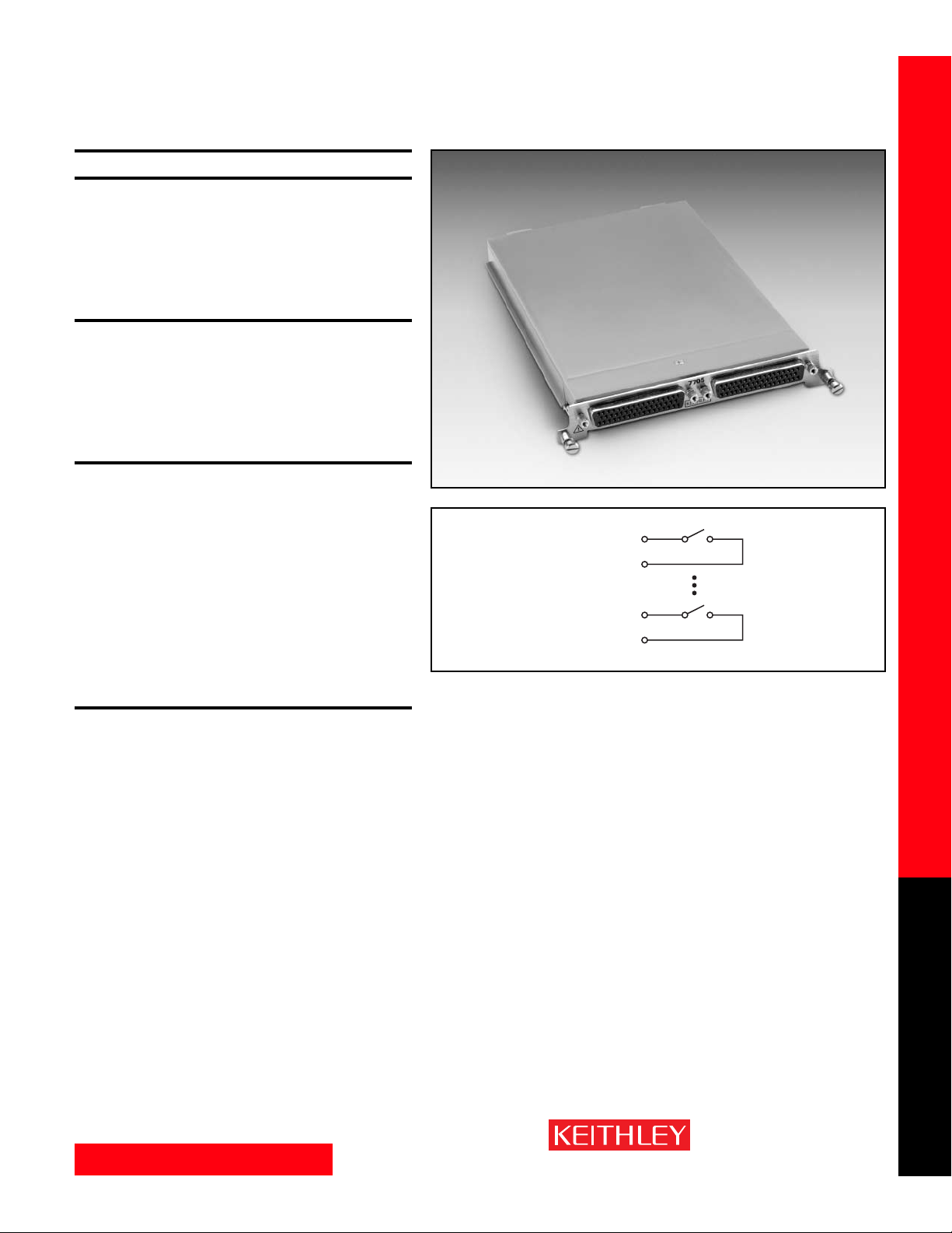
www.keithley.com
1.888.KEITHLEY (U.S. only)
A GREATER MEASURE OF CONFIDENCE
Model 7705 Specifications
SWITCH/MEASURE SYSTEMS
27
Integra Series Multimeter/Switch Systems
Modules
7705 40-CHANNEL CONTROL MODULE
FEATURES
• 40 channels designed for controlling power to the DUT, switching loads, controlling
light indicators and relays, etc.
•Two 50-pin female “D-sub” connectors are standard for secure hook-up and
quick teardown.
• 300V, 2A capacity.
•Two mating connectors with solder cup pins (Model 7788) are supplied.
• Relay closures stored in on-board memory.
GENERAL
RELAY SWITCH CONFIGURATION: 40 independent channels of 1-pole switching.
Isolated from internal DMM.
CONTACT CONFIGURATION: 1 pole Form A.
RELAY TYPE: Latching electromechanical.
CONNECTOR TYPE: Two 50-pin female D-sub connectors.
FIRMWARE: Specified for Model 2700 rev. A01, 2701 rev. A01, and 2750 rev. A01
or higher.
INPUTS
MAXIMUM SIGNAL LEVEL: 300VDC or rms, 2A switched, 60W (DC, resistive), 125VA
(AC, resistive).
CONTACT LIFE: Cold Switching: 10
8
closures.
At Maximum Signal Levels: 10
5
closures.
CHANNEL RESISTANCE (per conductor): <1Ω.
CONTACT POTENTIAL: ≤4µV per contact.
OFFSET CURRENT: <100pA.
ACTUATION TIME: 3ms.
ISOLATION: Channel to Channel: >10
9
Ω, <50pF.
Common Mode: >10
9
Ω, <100pF.
CROSSTALK (1MHz, 50Ωload): <–35dB.
INSERTION LOSS (50Ω source, 50Ω load): <0.3dB below 1MHz, <3dB below
10MHz.
COMMON MODE VOLTAGE: 300V between any terminal and chassis.
ENVIRONMENTAL
OPERATING ENVIRONMENT: Specified for 0°C to 50°C.
Specified to 80% R.H. at 35°C.
STORAGE ENVIRONMENT: –25°C to 65°C.
WEIGHT: 0.45kg (1 lb).
ACCESSORIES AVAILABLE:
Model 7705-MTC-2 50 Pin Male to Female DSUB Cable, 2m (6.6 ft).
Channel 1
(Channels 2–39)
Channel 40
IN
OUT
IN
OUT
Page 28
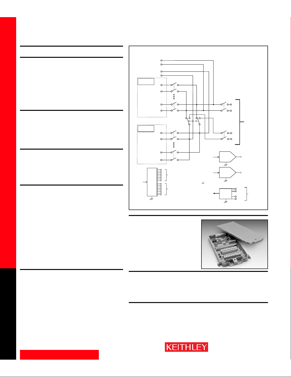
www.keithley.com
1.888.KEITHLEY (U.S. only)
A GREATER MEASURE OF CONFIDENCE
Model 7706 Specifications
SWITCH/MEASURE SYSTEMS
28
Integra Series Multimeter/Switch Systems
Modules
a
7706 ALL-IN-ONE I/O MODULE
FEATURES
• 20 channels of analog input (w/automatic CJC) for general-purpose measurement.
• 16 channels of digital output.
• Event counter/totalizer can monitor and control system components, such as
fixturing, limit switches, pass/fail indicators, external voltage sources, loads, door
closures, revolutions, etc., while performing mixed signal measurement.
• 300V, 1A capacity; 60W, 125VA maximum.
•Configurable as two independent banks of multiplexers.
•Two analog outputs (±12V, 5mA).
• Relay closures stored in on-board memory.
GENERAL
20 CHANNELS: 20 channels of 2-pole relay input.
All channels configurable to 4-pole.
RELAY TYPE: Latching electromechanical.
ACTUATION TIME: <3ms.
FIRMWARE: Specified for Model 2700 rev. A02 or B01, 2701 rev. A01, and 2750 rev.
A01 or higher.
CAPABILITIES
CHANNELS 1–20: Multiplex one of 20 2-pole or one of 10 4-pole signals into DMM.
Channels 21–25 are referenced to chassis ground.
CHANNELS 21–22: 16 Digital Outputs.
CHANNELS 23–24: Analog Voltage Output (2).
CHANNELS 25: Totalize Input.
INPUTS
MAXIMUM SIGNAL LEVEL (Channels 1–20): 300V DC or rms, 1A switched, 60W,
125VA maximum.
CONTACT LIFE (typ.): >10
5
operations at max. signal level: >108operations cold
switching.
CONTACT RESISTANCE: <1Ω at end of contact life.
CONTACT POTENTIAL: <±2µV typical per contact, 3µV max.
OFFSET CURRENT: <100pA.
CONNECTOR TYPE: Screw terminal, #20 AWG wire size.
ISOLATION BETWEEN ANY TWO TERMINALS: >10
9
Ω, <100pF.
ISOLATION BETWEEN ANY TERMINAL AND EARTH: > 10
9
Ω, <200pF.
CROSS TALK (10MHz, 50ΩLoad): <–35dB.
INSERTION LOSS (50Ω Source, 50Ω Load): <0.1dB below 1MHz.
<3dB below 2Mhz.
COMMON MODE VOLTAGE: 300V between any terminal and chassis.
TEMPERATURE ACCURACY USING INTERNAL CJC: 1.0°C (see mainframe specifica-
tion for details).
TOTALIZE INPUT
MAXIMUM COUNT: 232–1.
TOTALIZE INPUT: 100kHz (max), rising or falling edge, programmable.
SIGNAL LEVEL: 1Vp-p (min), 42Vpk (max).
THRESHOLD: 0V or TTL, jumper selectable.
DATE INPUT: TTL-Hi, TTL-Lo, or none.
COUNT RESET: manual or Read+Reset.
READ SPEED: 50/s.
ANALOG VOLTAGE OUTPUT
DAC 1, 2: ±12V in 1mV increments, non-isolated.
RESOLUTION: 1mV.
I
OUT
: 5mA max.
SETTLING TIME: 1ms to 0.01% of output.
ACCURACY ±(% of output + mV):
1 year ±5°C: 0.15% + 19mV;
90 day ±5°C: 0.1% + 19mV;
24 hour ±1°C: 0.04% + 19mV.
TEMPERATURE COEFFICIENT:
±(0.015% + 1mV)/°C.
DIGITAL OUTPUT
V
OUT
(L): <0.8V @ Iout = 400mA.
V
OUT
(H): >2.4V @ Iout = 1mA.
V
OUT
(H)MAX.: <42V with external open drain pull-up.
WRITE SPEED: 50/s.
ENVIRONMENTAL
OPERATING ENVIRONMENT: Specified for 0°C to 50°C.
Specified to 80% R.H. at 35°C.
STORAGE ENVIRONMENT: –25°C to 65°C.
WEIGHT: 0.5kg (1.1 lbs).
HI
Input
LO
HI
Sense
Cold junction
Ref x2
Channel 1
(Channels 2–9)
Channel 10
Cold junction
Ref x2
Channel 11
(Channels 12–19)
Channel 20
LO
HI
LO
HI
LO
Channel 26
2-Pole (Open)
4-Pole (Closed)
(see Note)
HI
LO
HI
LO
Bit
0
1
2
3
Channel 21
4
5
16
Digital
Output
6
7
0
1
2
3
4
5
6
7
NOTE Non-isolated
Channel 22
NOTES Channels 26–28 in this schematic
grounds ( )
are referenced to
chassis ground.
refer to the designations used for
control and not actual available channels.
Channels 26, 27, and 28 can be individually
controlled using ROUTe:MULTiple if the
module is not to be connected to the
internal DMM.
For more information, refer to the
ROUTe:MULTiple command section
in the Model 2700, 2701, or 2750 User’s Manu
Channel 28
(see Note)
Backplane
isolation
HI
Input
LO
HI
Sense
LO
Channel 23
Channel 24
+IN
–IN
+GATE
–GATE
To Model 2700,
2701, or 2750
Backplane
Channel 25
Channel 27
(see Note)
Backplane
isolation
16
16
32
Channel 23
DAC
Channel 24
DAC
Tot a lizer
Page 29
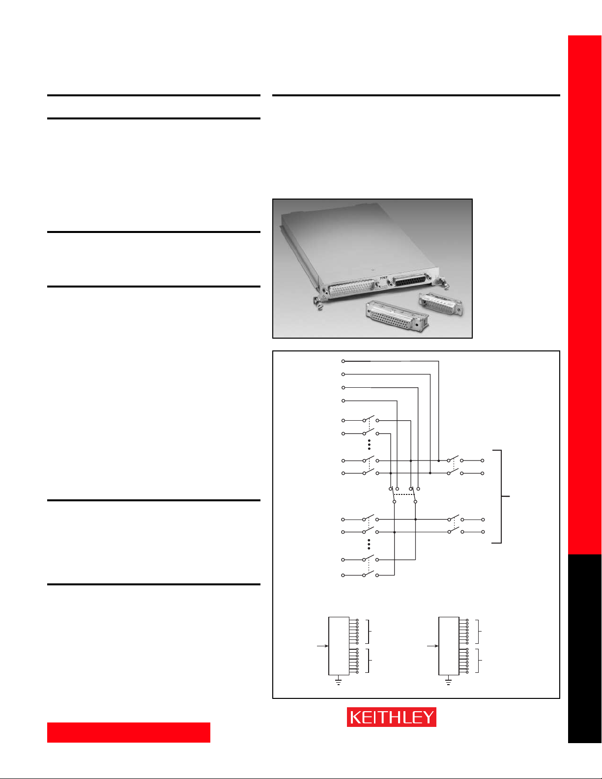
www.keithley.com
1.888.KEITHLEY (U.S. only)
A GREATER MEASURE OF CONFIDENCE
Model 7707 Specifications
SWITCH/MEASURE SYSTEMS
29
Integra Series Multimeter/Switch Systems
Modules
a
7707 MULTIPLEXER-DIGITAL I/O MODULE
GENERAL
10 CHANNELS: 10 channels of 2-pole relay input.
All channels configurable to 4-pole.
RELAY TYPE: Latching electromechanical.
ACTUATION TIME: <3ms.
FIRMWARE: Specified for Model 2700 rev. B03, 2701 rev. A01, and 2750 rev. A01
or higher.
CAPACITY: Model 2700: (1) 7707 and (1) 77XX, except 7706.
Model 2701: Any combination of 77XX modules.
Model 2750: (4) 7707 and (1) 77XX, except 7706. A 7706 module may be
substituted for a 7707 module.
CAPABILITIES
CHANNELS 1–10: Multiplex one of 10 2-pole or one of 5 4-pole signals into DMM.
CHANNELS 11–14: 32 Digital Inputs/Outputs referenced to chassis ground.
THERMAL PROTECTION: Channels 11–14 are thermally protected to 1A.
INPUTS (CHANNELS 1–10)
MAXIMUM SIGNAL LEVEL: Any Channel to Any Channel (1–10): 300VDC or
300Vrms (425V peak) for AC waveforms, 1A switched, 60W, 125VA maximum.
SAFETY CATEGORY: Conforms to European Union Directive 73/23/EEC EN 61010-1,
CAT I.
CONTACT LIFE (typ.): >10
5
operations at max. signal level: >108operations cold
switching.
CONTACT RESISTANCE: <1Ω any path and additional 1Ω at end of contact life.
CONTACT POTENTIAL: <6µV typical per contact pair and additional 5µV with
Channels 11–14 at rate V
OUT
(L).
OFFSET CURRENT: <100pA.
CONNECTOR TYPE: 50-pin male D-shell, Channels 11–14.
25-pin female D-shell, Channels 1–10.
Supplied with female and male IDC ribbon cable connectors.
ISOLATION BETWEEN ANY TWO TERMINALS: >10
9
Ω, <100pF with isolation chan-
nels 16 and 17 open.
ISOLATION BETWEEN ANY TERMINAL AND EARTH: > 10
9
Ω, <200pF.
CROSS TALK (10MHz, 50ΩLoad): <–35dB.
INSERTION LOSS (50Ω Source, 50Ω Load): <0.1dB below 1MHz.
<3dB below 2MHz.
COMMON MODE VOLTAGE: 300VDC or 300Vrms (425V peak) for AC waveforms
between any terminal and chassis.
DIGITAL INPUT/OUTPUT (CHANNELS 11–14)
VIN(L): <0.8V (TTL).
V
IN
(H): >2V (TTL).
V
OUT
(L): <1.0V @ I
OUT
= 100mA.
V
OUT
(H): >2.4V @ I
OUT
= 1mA.
V
OUT
(H)MAX.: <40V with external open drain pull-up.
READ/WRITE SPEED: 50/s.
ENVIRONMENTAL
OPERATING ENVIRONMENT: Specified for 0°C to 50°C.
Specified to 50% R.H. at 35°C.
STORAGE ENVIRONMENT: –25°C to 65°C.
WEIGHT: <0.5kg (1.1 lbs).
ACCESSORIES AVAILABLE:
Model 7790 50/50/25 Pin Female/Male D-Shell IDC Connectors
Model 7705-MTC-2 50 Pin Male to Female DSUB Cable, 2m (6.6 ft).
Model 7707-MTC-2 25 Pin Male to Female DSUB Cable, 2m (6.6 ft).
FEATURES
• 10 channels of analog input for general-purpose measurement.
• 32 channels of digital input and output (four 8-bit ports) for I/O control.
• 300V, 1A capacity; 60W, 125VA maximum (analog).
•Configurable as two independent banks of multiplexers.
• 33V, 100mA capacity (digital).
•Two mating IDC connectors supplied (Model 7790).
• Digital outputs are short circuit protected.
• Relay closures stored in on-board memory.
1–16
HI
LO
HI
LO
HI
LO
HI
LO
HI
LO
HI
LO
Digital I/O
DIO
Channel 17
(see Note)
Backplane
isolation
Channel 15
2-Pole (Open)
4-Pole (Closed)
(see Note)
Bit
0
1
2
3
Channel 11
4
5
6
7
0
1
2
3
Channel 12 Channel 14
4
5
6
7
Channel 16
(see Note)
Backplane
isolation
NOTES Channels 15–17 in this schematic
Digital I/O
17–32
DIO
Card Input
Card Sense
Channel 1
(Channels 2–4)
Channel 5
Channel 6
(Channels 7–9)
Channel 10
HI
Input
LO
To
Internal
DMM
HI
Sense
LO
refer to the designations used for
control and not actual available channels.
For more information, refer to the
ROUTe:MULT command section
in the Model 2700, 2701, or 2750 User’s Manu
Bit
0
1
2
3
Channel 13
4
5
6
7
0
1
2
3
4
5
6
7
Page 30
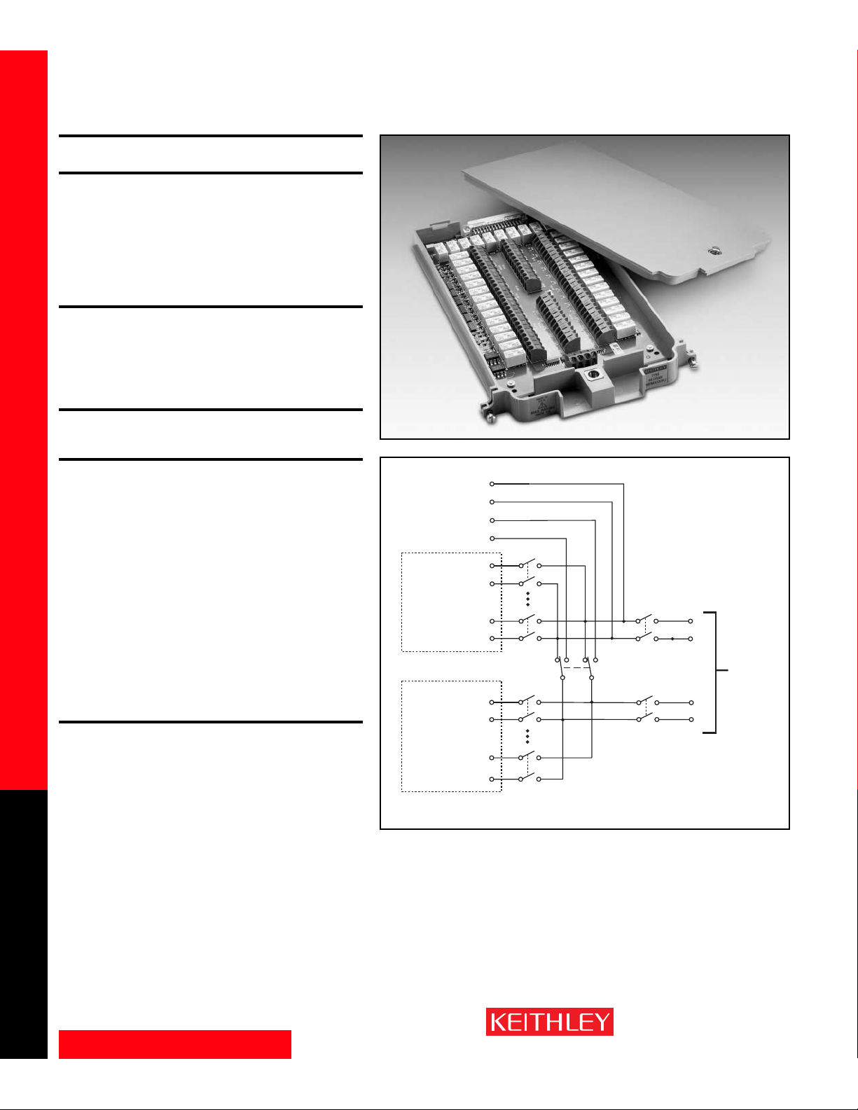
www.keithley.com
1.888.KEITHLEY (U.S. only)
A GREATER MEASURE OF CONFIDENCE
Model 7708 Specifications
SWITCH/MEASURE SYSTEMS
30
Integra Series Multimeter/Switch Systems
Modules
7708 40-CHANNEL DIFFERENTIAL MULTIPLEXER
MODULE
FEATURES
• 40 differential channels for general-purpose measurements.
• 2- or 4-wire measurements.
• Oversize screw terminal connection blocks are standard for easier connection.
• 300V, 1A capacity for voltage channels; 60W, 125VA.
•Configurable as two independent banks of multiplexers.
• Built-in CJC sensors automatically linearize thermocouples.
• Relay closures stored in on-board memory.
GENERAL
40 CHANNELS: 40 channels of 2-pole relay input. All channels configurable to 4-pole.
RELAY TYPE: Latching electromechanical.
ACTUATION TIME: <3ms.
FIRMWARE: Specified for Model 2700 rev. B02, 2701 rev. A01, and 2750 rev. A01
or higher.
CAPABILITIES
CHANNELS 1–40: Multiplex one of 40 2-pole or one of 20 4-pole signals into DMM.
INPUTS
MAXIMUM SIGNAL LEVEL:
Channels (1–40): 300V DC or rms, 1A switched, 60W, 125VA maximum.
CONTACT LIFE (typ): >10
5
operations at max. signal level.
>10
8
operations cold switching.
CONTACT RESISTANCE: <1Ω at end of contact life.
CONTACT POTENTIAL: <±500nV typical per contact, 1µV max.
<±500nV typical per contact pair, 1µV max.
OFFSET CURRENT: <100pA.
CONNECTOR TYPE: Screw terminal, #20 AWG wire size.
ISOLATION BETWEEN ANY TWO TERMINALS: >10
10
Ω, <100pF.
ISOLATION BETWEEN ANY TERMINAL AND EARTH: >10
9
Ω, <200pF.
CROSS TALK (10MHz, 50ΩLoad): <–40dB.
INSERTION LOSS (50Ω Source, 50Ω Load): <0.1dB below 1MHz.
<3dB below 2MHz.
COMMON MODE VOLTAGE: 300V between any terminal and chassis.
TEMPERATURE ACCURACY USING INTERNAL CJC: 1.0°C (see mainframe specifica-
tion for details).
ENVIRONMENTAL:
OPERATING ENVIRONMENT: Specified for 0°C to 50°C.
Specified to 80% R.H. at 35°C.
STORAGE ENVIRONMENT: –25°C to 65°C.
WEIGHT: 0.52kg (1.16 lb).
ACCESSORIES AVAILABLE:
Model 7401 Type K Thermocouple Wire, 30.5m (100 ft).
Card Input
Card Sense
Cold Junction
Ref XY
Channel 1
(Channels 2–19)
Channel 20
Cold Junction
Ref XY
Channel 21
(Channels 22–39)
Channel 40
HI
LO
HI
LO
HI
LO
HI
LO
HI
LO
HI
LO
Channel 43
2-Pole / 4-Pole
(see Note)
Channel 45
(see Note)
Backplane
isolation
Channel 44
(see Note)
Backplane
isolation
NOTE Channels 43–45 in this schematic
refer to the designations used for
control and not actual available channels.
For more information, refer to the
ROUTe:MULTiple command section
in the Model 2700, 2710, or 2750 User’s Manual.
HI
Input
LO
HI
Sense
LO
To Model 2700,
2701, or 2750
Backplane
Page 31
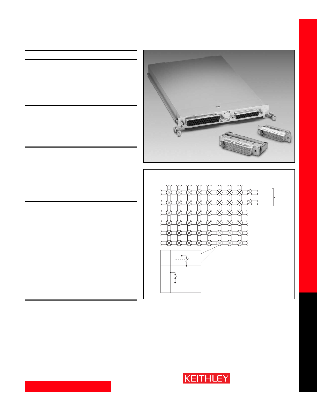
www.keithley.com
1.888.KEITHLEY (U.S. only)
A GREATER MEASURE OF CONFIDENCE
Model 7709 Specifications
SWITCH/MEASURE SYSTEMS
31
Integra Series Multimeter/Switch Systems
Modules
7709 6×8 MATRIX MODULE
FEATURES
•Automatic 2- or 4-wire connection to DMM
•6 row×8 column matrix
•Two female “D-sub” connectors are standard for secure hook-up and quick
teardown.
• 300V, 1A capacity.
•Two mating IDC connectors for ribbon cable (Model 7790) are supplied.
• Relay closures stored in on-board memory.
GENERAL
MATRIX CONFIGURATION: 6 rows × 8 columns.
CONTACT CONFIGURATION: 2 pole Form A.
FIRMWARE: Specified for Model 2700 rev. B03, Model 2701 rev. A01, and Model 2750
rev. A01 or higher.
RELAY TYPE: Latching electromechanical.
ACTUATION TIME: <3ms.
CAPABILITIES
DMM CONNECTION:
2-Wire Functions
Row 1, channels 1–8, through channel 50.
4-Wire Functions
Row 1, channels 1–4 (Source) through channel 50 and Row 2, channels 13–16
(Sense), through channel 49.
CLOSE CHANNEL: CLOSE command connects channels 1–8 to DMM. For 4-wire,
channels 1–4 are automatically paired with channels 13–16. ROUTe:MULTiple
allows any combination of rows and columns to be connected at the same time.
INPUTS
MAXIMUM SIGNAL LEVEL: Any Channel to Any Channel (1–48): 300VDC or
300Vrms (425V peak) for AC waveforms, 1A switched, 60W, 125VA maximum.
SAFETY: Conforms to European Union Directive 73/23/EEC EN61010-1, CAT I.
CONTACT LIFE (typ): >10
5
operations at max signal level.
>10
8
operations cold switching.
CONTACT RESISTANCE: <1Ω any path and additional 1Ω at end of contact life.
CONTACT POTENTIAL: <3µV per contact pair.
OFFSET CURRENT: <100pA.
CONNECTOR TYPE: 50-pin female D-shell for rows and columns.
25-pin female D-shell for “daisy-chain” rows.
Supplied with male IDC ribbon cable connectors.
ISOLATION BETWEEN ANY TWO TERMINALS: >10
9
Ω, <200pF.
ISOLATION BETWEEN ANY TERMINAL AND EARTH: >10
9
Ω, <400pF.
CROSS TALK (1MHz, 50ΩLoad): <–35dB.
INSERTION LOSS (50Ω Source, 50Ω Load): <0.35dB below 1MHz.
<3dB below 2MHz.
COMMON MODE VOLTAGE: 300VDC or 300Vrms (425V peak) for AC waveforms
between any terminal and chassis.
ENVIRONMENTAL:
OPERATING ENVIRONMENT: Specified for 0°C to 50°C.
Specified to 50% R.H. at 35°C.
STORAGE ENVIRONMENT: –25°C to 65°C.
WEIGHT: <0.52kg (1.16 lb).
ACCESSORIES AVAILABLE:
Model 7789 50/25 Pin Male D-Shell Solder Cup Connectors
Model 7790 50/50/25 Pin Female/Male D-Shell IDC Connectors
Model 7705-MTC-2 50 Pin Male to Female DSUB Cable, 2m (6.6 ft).
Model 7707-MTC-2 25 Pin Male to Female DSUB Cable, 2m (6.6 ft).
Rows
1 2 3 4 5
12345 678
1
910111213 141516
2
17 18 19 20 21 22 23 24
3
25 26 27 28 29 30 31 32
4
33 34 35 36 37 38 39 40
5
41 42 43 44 45 46 47 48
6
Columns
678
50
49
HI
Matrix Crosspoint
LO
HI
Input
LO
HI
LO
Sense
To DMM
Backplane
Page 32
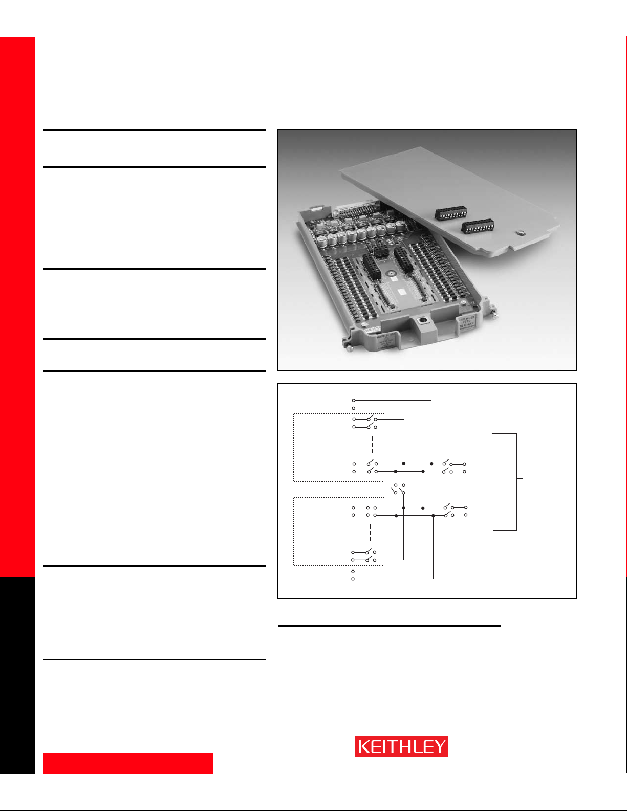
www.keithley.com
1.888.KEITHLEY (U.S. only)
A GREATER MEASURE OF CONFIDENCE
Model 7710 Specifications (Preliminary)
SWITCH/MEASURE SYSTEMS
32
Integra Series Multimeter/Switch Systems
Modules
7710 20-CHANNEL SOLID STATE/LONG-LIFE
DIFFERENTIAL MULTIPLEXER W/AUTOMATIC CJC
FEATURES
• Solid-state relays for long life and low maintenance (100 times longer life than
mechanical relays)
• Higher scanning speeds of up to 500 channels per second
•Automatic CJC provides guaranteed 0.7°C temperature accuracy with no extra
accessories required for thermocouple measurements
• Removable screw terminals offer simpple, quick connections
•20 channels for general purpose measurements
• Configurable as two independent banks of multiplexers
GENERAL
CHANNELS: 20 channels of 2-pole relay input. All channels configurable to 4-pole.
RELAY TYPE: Solid State Opto-Coupled FET.
ACTUATION TIME: <0.5ms (100mA load).
FIRMWARE: Specified for Model 2700 Rev. B05, Model 2750 Rev. A04, and Model 2701
Rev. A01.
CAPABILITIES
CHANNELS 1–20: Multiplex one of 20 2-pole or one of 10 4-pole signals into DMM.
INPUTS
MAXIMUM SIGNAL LEVEL: Any channel to any channel (1–20): 60VDC or 42V rms,
100mA switched, 6W, 4.2VA maximum.
COMMON MODE VOLTAGE: 300VDC or 300Vrms (425V peak) maximum between
any terminal and chassis.
RELAY LIFE (TYP): >10
5
operational hours max. signal level or 1010operations
(guaranteed by design).
RELAY DRIVE CURRENT: 6mA per channel continuous, 25mA during initial pulse.
CHANNEL RESISTANCE (per conductor): <5Ω.
CONTACT POTENTIAL: <1µV per pair.
OFFSET CURRENT: <3nA @ 23°C (per channel); additional 0.13nA/°C >23°C.
CONNECTOR TYPE: 3.5mm removable screw terminals, #20 AWG wire size.
ISOLATION BETWEEN ANY TWO TERMINALS: >10
9
Ω, <100pF.
ISOLATION BETWEEN ANY TERMINAL AND EARTH: >10
9
Ω, <100pF.
CROSSTALK (CH-CH, 300kHz, 50Ω Load) : <–40dB.
INSERTION LOSS (50Ω Source, 50Ω Load): <0.5dB below 100kHz, <3dB below
2MHz.
TEMPERATURE ACCURACY USING INTERNAL CJC: 0.7°C (see mainframe specifica-
tions for details).
SCANNING SPEEDS (see mainframe specifications for details)
Multiple Channels, Into Memory Channels/s
2700 2701 2750
7710 Scanning DCV 180/s 500/s 230/s
7710 Scanning DCV with Limits or Time Stamp On 170/s 500/s 230/s
7710 Scanning DCV alternating 2WΩ 45/s 130/s 60/s
Multiple Channels, Into and Out of Memory to GPIB
or Ethernet
Channels/s
2700 2701 2750
7710 Scanning DCV 145/s 440/s 210/s
7710 Scanning DCV with Limits or Time Stamp On 145/s 440/s 210/s
7710 Scanning DCV alternating 2WΩ 40/s 130/s 55/s
ENVIROMENTAL
OPERATING ENVIRONMENT: Specified for 0°C to 50°C. Specified for 80% R.H.
at 35°C.
STORAGE ENVIROMENT: –25° to 65°C.
WEIGHT: 0.45kg (1 lb).
ACCESSORIES AVAILABLE: Model 7401 Type K Thermocouple Wire, 30.5m (100 ft).
CARD SOURCE
CHANNEL 1
Cold Junction
Ref 3x
CHANNEL 10
CHANNEL 11
Cold Junction
Ref 3x
CHANNEL 20
CARD SENSE
HI
LO
HI
LO
HI
LO
CHANNEL 23
2-Pole (closed)
4-Pole (opened)
HI
LO
HI
LO
HI
LO
HI
CHANNEL 21
LO
HI
CHANNEL 22
LO
To Mainframe
Backplane
Page 33
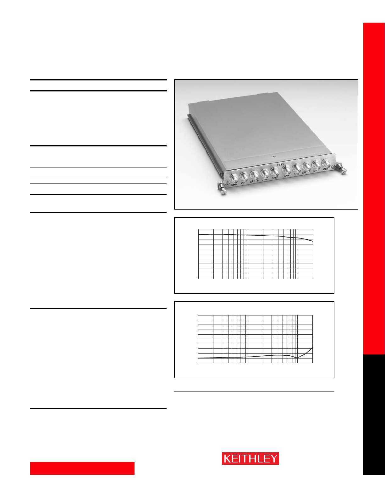
www.keithley.com
1.888.KEITHLEY (U.S. only)
A GREATER MEASURE OF CONFIDENCE
Model 7711 Specifications
SWITCH/MEASURE SYSTEMS
33
Integra Series Multimeter/Switch Systems
Modules
7711 2GHz 50Ω RF MODULE
FEATURES
• Outstanding signal routing performance to 2GHz
• Dual 1×4 configuration
• Rear panel connections
• On-board switch closure counter
• On-board S-parameter storage
• Switch up to 60VDC
AC PERFORMANCE (End of Life)
For Z
load
= Z
source
= 50Ω
<100 MHz 500 MHz 1 GHz 1.5 GHz 2 GHz
Insertion Loss <0.4 dB <0.6 dB <1.0 dB <1.2 dB <2.0 dB
Max.
VSWR Max. <1.1 <1.2 <1.2 <1.3 <1.7
2
Ch-Ch Crosstalk1–85 dB –65 dB –55 dB –45 dB –35 dB
Max.
1
Specification assumes 50Ω termination.
2
Add 0.1VSWR after 5×10
5
closures (no load).
INPUTS (CHANNELS 1-8)
MAXIMUM SIGNAL LEVEL: Any channel to any channel or chassis (1–8): 30Vrms (42V
peak for AC waveforms) or 60VDC, 0.5A.
MAXIMUM POWER: 20W per module, 10W per channel (refer to 7711/7712 Manual
PA-818 for measurement considerations).
SAFETY: Conforms to European Union Directive 73/23/EEC EN61010-1, CAT I.
EMC: Conforms with European Union Directive 89/336/EEC; EN61326-1.
ISOLATION: Multiplexer to Multiplexer: >1GΩ.
Center to Shield: >1GΩ, <25pF.
Channel to Channel: >100MΩ.
CONTACT LIFE: 1×10
6
no load, 1×10
5
rated load (resistive load).
CONTACT POTENTIAL: <6µV.
CONTACT RESISTANCE: <0.5Ω (initial), <1Ω (end of life).
RISE TIME: <300ps (guaranteed by design).
SIGNAL DELAY: <3ns.
GENERAL
RELAY TYPE: High frequency electromechanical.
CONTACT CONFIGURATION: Dual 1×4 multiplexer, single pole four throw, Channels
1 and 5 are normally closed.
NOTES: One channel in each multiplex bank is always closed to the corresponding
OUT connector.
CLOSE CHANNEL: ROUTe:CLOSe allows a single channel in a multiplex bank to be
closed. ROUTe:MULTiple:CLOSe allows two channels (one in each bank) to be
closed at one time.
OPEN CHANNEL: ROUTe:OPEN:ALL closes CH1 and CH5 to OUT A and OUT B
respectively.
ACTUATION TIME: <10ms.
FIRMWARE: Specified for Model 2700 rev. B04, 2701 rev. A01, and 2750 rev. A03 or
higher.
CONNECTOR TYPE: Ten external rear panel SMA connectors.
MATING TORQUE: 0.9 N·m (8 in-lb).
ENVIRONMENTAL
OPERATING ENVIRONMENT: Specified for 0°C to 50°C. Specified for 80% RH at 35°C.
STORAGE ENVIRONMENT: –25°C to 65°C.
WEIGHT: <0.5kg (1.1 lb).
ACCESSORIES AVAILABLE
7051-2 BNC Cable, male to male, 0.6m (2 ft.)
7051-5 BNC Cable, male to male, 1.5m (5 ft.)
7051-10 BNC Cable, male to male, 3.0m (10 ft.)
7711-BNC-SMA Male SMA to female BNC Cables (5),
0.15m (0.5 ft)
7712-SMA-1 SMA Cable, male to male, 1m (3.3 ft)
7712-SMA-N Female SMA to Male N-Type Adapter
S46-SMA-0.5 SMA Cable, male to male, 0.15m (0.5 ft.)
S46-SMA-1 SMA Cable, male to male, 0.3m (1 ft.)
Typical Insertion Loss
0dB
–1dB
–2dB
–3dB
–4dB
10 100 1000 2000
Frequency (MHz)
Typical VSWR
1.8
1.6
1.4
1.2
1.0
10 100 1000 2000
Frequency (MHz)
Page 34
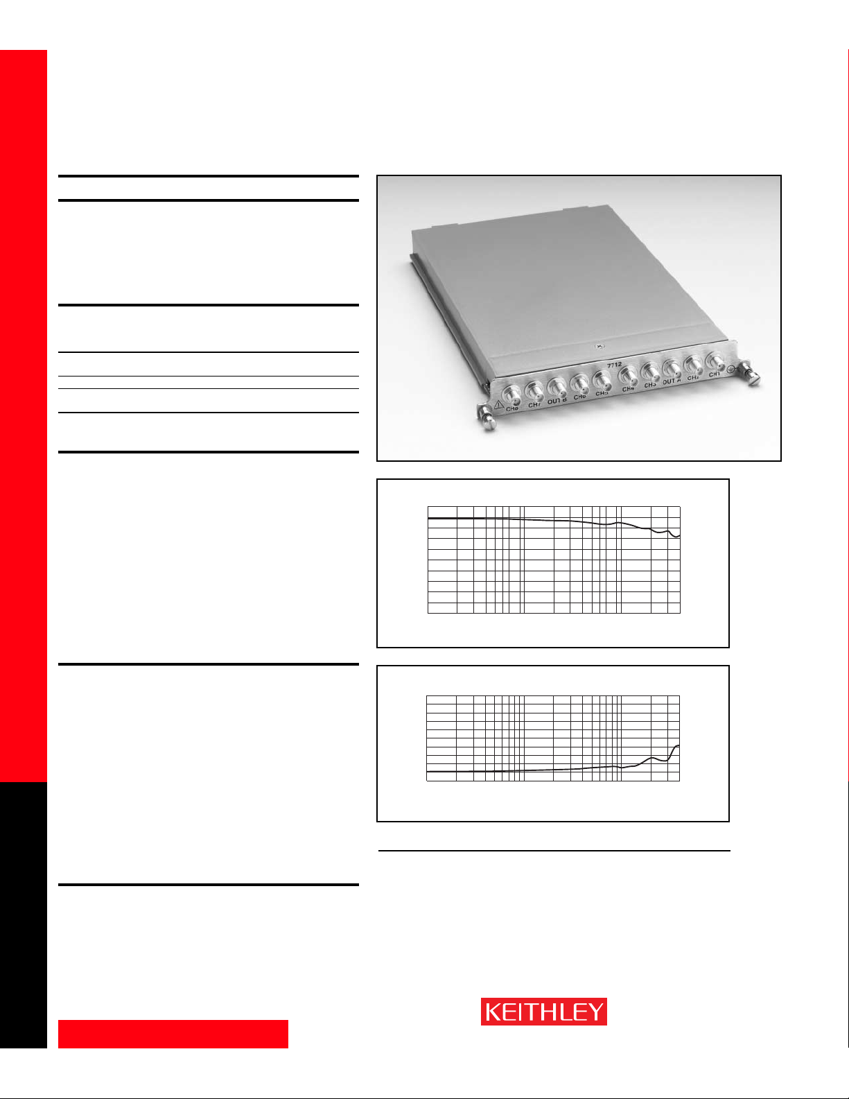
www.keithley.com
1.888.KEITHLEY (U.S. only)
A GREATER MEASURE OF CONFIDENCE
Model 7712 Specifications
SWITCH/MEASURE SYSTEMS
34
Integra Series Multimeter/Switch Systems
Modules
7712 3.5GHz 50Ω RF MODULE
FEATURES
• 3.5GHz bandwidth
•Dual 1×4 configuration
• Rear panel SMA connections
• On-board switch closure counter
•On-board S-parameter storage
AC PERFORMANCE (End of Life)
For Z
load
= Z
source
= 50Ω
<500 MHz 1 GHz 2.4 GHz 3.5 GHz
Insertion Loss <0.5 dB <0.65 dB <1.1 dB <1.3 dB
MAX
VSWR MAX <1.15 <1.2 <1.45
2
<1.45
Ch-Ch Crosstalk
1
–75 dB –70 dB –50 dB –45 dB
MAX
1
Specification assumes 50Ω termination.
2
Add 0.1VSWR after 5×10
5
closures (no load).
INPUTS (CHANNELS 1-8)
MAXIMUM SIGNAL LEVEL: Any channel to any channel or chassis (1–8): 30Vrms
(42V peak for AC waveforms) or 42VDC, 0.5A.
MAXIMUM POWER: 20W per module, 10W per channel (refer to 7711/7712 Manual
PA-818 for measurement considerations).
SAFETY: Conforms to European Union Directive 73/23/EEC EN61010-1, CAT I.
EMC: Conforms with European Union Directive 89/336/EEC; EN61326-1.
ISOLATION: Multiplexer to Multiplexer: >1GΩ.
Center to Shield: >1GΩ, <20pF.
Channel to Channel: >100MΩ.
CONTACT LIFE: 5×10
6
no load, 1×10
5
rated load (resistive load).
CONTACT POTENTIAL: <12µV.
CONTACT RESISTANCE: <0.5Ω (initial), <1Ω (end of life).
RISE TIME: <200ps (guaranteed by design).
SIGNAL DELAY: <1.5ns.
GENERAL
RELAY TYPE: High frequency electromechanical.
CONTACT CONFIGURATION: Dual 1×4 multiplexer, single pole four throw, Channels
1 and 5 are normally closed.
NOTES: One channel in each multiplex bank is always closed to the corresponding
OUT connector.
CLOSE CHANNEL: ROUTe:CLOSe allows a single channel in a multiplex bank to be
closed. ROUTe:MULTiple:CLOSe allows two channels (one in each bank) to be
closed at one time.
OPEN CHANNEL: ROUTe:OPEN:ALL closes CH1 and CH5 to OUT A and OUT B
respectively.
ACTUATION TIME: <10ms.
FIRMWARE: Specified for Model 2700 rev. B04, 2701 rev. A01, and 2750 rev. A03
or higher.
CONNECTOR TYPE: Ten external rear panel SMA connectors.
MATING TORQUE: 0.9 N·m (8 in-lb).
ENVIRONMENTAL
OPERATING ENVIRONMENT: Specified for 0°C to 50°C. Specified for 80% RH at 35°C.
STORAGE ENVIRONMENT: –25°C to 65°C.
WEIGHT: <0.5kg (1.1 lb).
ACCESSORIES AVAILABLE
7712-SMA-1 SMA Cable, male to male, 1m (3.3 ft)
7712-SMA-N Female SMA to Male N-Type Adapter
S46-SMA-0.5 SMA Cable, male to male, 0.15m (0.5 ft.)
S46-SMA-1 SMA Cable, male to male, 0.3m (1 ft.)
Typical Insertion Loss
0dB
–1dB
–2dB
–3dB
–4dB
10 100 1000 4000
Frequency (MHz)
Typical VSWR
1.8
1.6
1.4
1.2
1.0
10 100 1000 4000
Frequency (MHz)
Page 35
www.keithley.com
1.888.KEITHLEY (U.S. only)
A GREATER MEASURE OF CONFIDENCE
System Configuration Examples
SWITCH/MEASURE SYSTEMS
35
Integra Series Multimeter/Switch Systems
Page 36
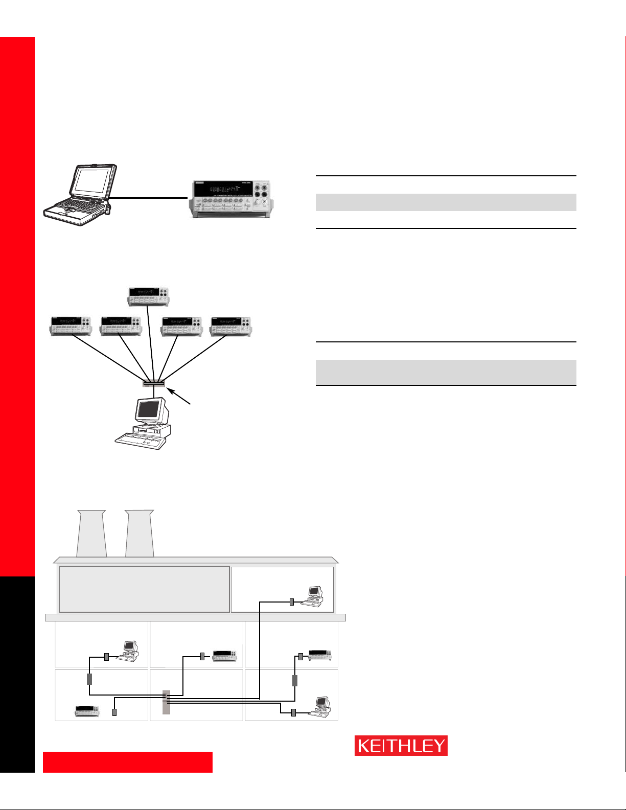
www.keithley.com
1.888.KEITHLEY (U.S. only)
A GREATER MEASURE OF CONFIDENCE
System Configuration Examples
SWITCH/MEASURE SYSTEMS
36
Integra Series Multimeter/Switch Systems
Server
Router
Router
GPIB Controller
or Ethernet Hub
Simple Computer to Single Instrument Control
Single Computer to Multiple Instruments
Multiple Computers to Multiple Instruments–Ethernet Only
Maximum Maximum
Interface Distance Speed Cable Type
RS-232 ~15 m† 115.2 kb/s (2701) Null modem cable
19.2 kb/s (2700, 2750) Keithley Model 7009-5
GPIB 2 m 1 MB/s Standard GPIB cable
Keithley Model 7007-*
Ethernet Hardwired: 100 m 100 Mb/s RJ-45 crossover cable
Wireless: >16 km
† RS-232 maximum distance is heavily dependent on the baud rate setting. Very slow baud rates can
be operated at distances longer than 15m, while faster baud rates may require cables shorter than
15m.
Maximum No. Maximum Maximum
Interface of Instruments Distance Speed Cable Type
GPIB 14 per controller 2m per cable 1 MB/s Standard GPIB cable
20m per controller Keithley Model 7007-*
Ethernet ∞ Hardwired: 100m 100 Mb/s Standard RJ-45
per cable straight-through cable
Wireless: >16 km
Call or visit www.keithley.com for Technical Note #2393,
“Network Primer and Programming Tutorial for the Model 2701
Ethernet-Based DMM/Data Acquisition System.” This document
explains the basic principles for using instruments over a network and programming methods for Ethernet.
Page 37
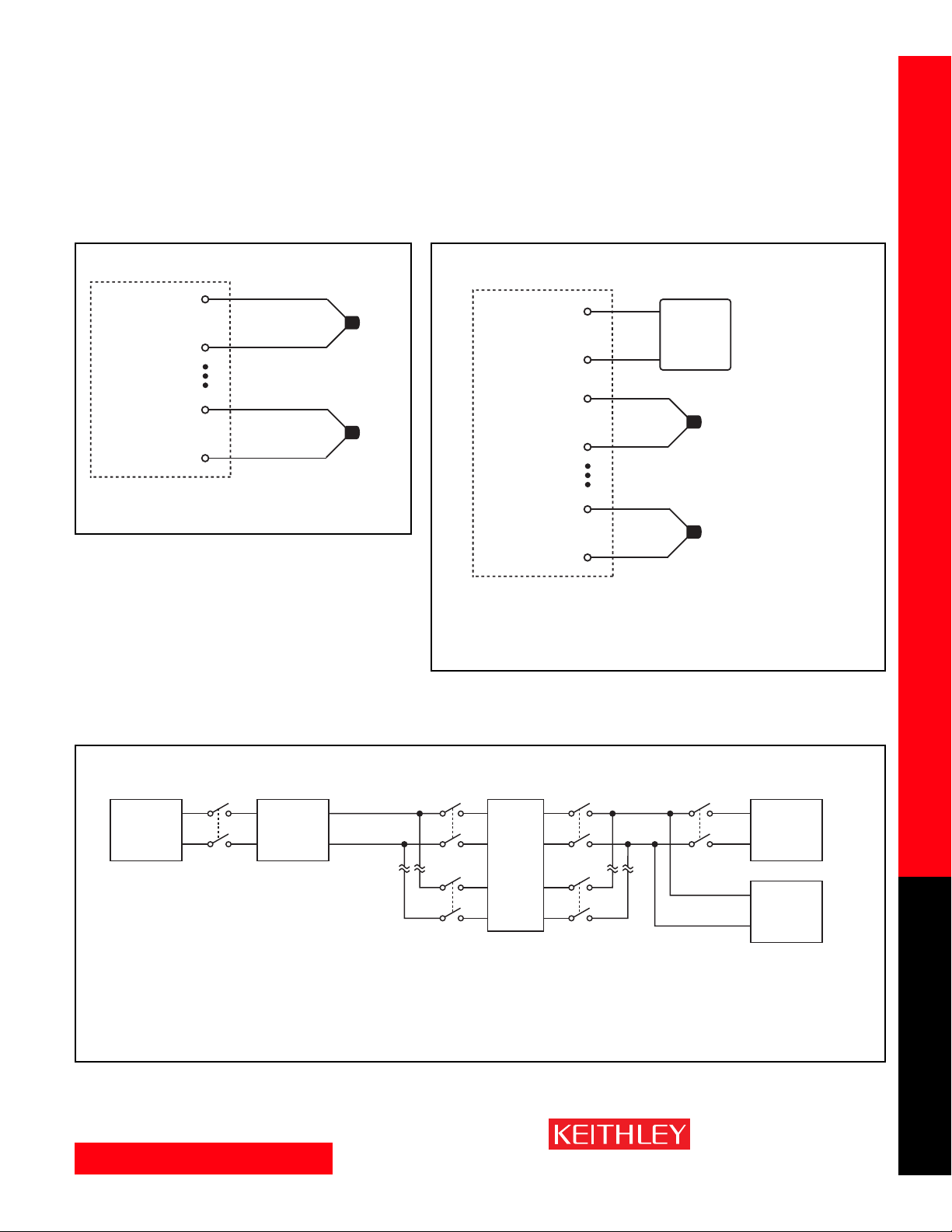
www.keithley.com
1.888.KEITHLEY (U.S. only)
A GREATER MEASURE OF CONFIDENCE
System Configuration Examples
SWITCH/MEASURE SYSTEMS
37
Integra Series Multimeter/Switch Systems
Thermocouple connections
NOTE: The red lead is the LO signal on all thermocouples.
7708 Configuration Examples
Thermocouple Configuration Example Using
Internal CJC
Thermocouple connections
Dual multiplexer mode example #1
NOTE: The red lead is the LO signal on all thermocouples.
This applies to U.S. standards.
Thermocouple Configuration Example Using External CJC
HI
Channel 1
LO
(Channels 2–19)
HI
Channel 20
LO
Thermocouple
HI
Channel 1
LO
HI
Channel 2
LO
(Channels 3–39)
HI
Channel 40
LO
NOTE: If an RTD is connected as the cold junction reference,
Channel 21 will be used for the sense leads of the RTD and
is not available for connection of a thermocouple.
Externally
supplied
cold
junction
reference*
Thermocouple
*Connect Thermistor
or RTD (see Note)
Internal
DMM
DC Power
Ch. 44
See Model 7708 specifications.
Channel 43 .....Closed
Channel 44 .....Open
Channel 45 .....Closed for DMM
measure
External
Supply
HI
Card Sense
LO
Ch. 21
Ch. 1
HI
Internal
DMM
.
.
.
DUT
.
.
.
Ch. 45
LO
HI
External
Ch. 40
Ch. 20
Scope
LO
NOTE: This configuration example can be duplicated with
the 7700, 7701, 7702, 7703, 7706, 7707, and 7708
modules. See module specifications for their channel
configurations.
Page 38
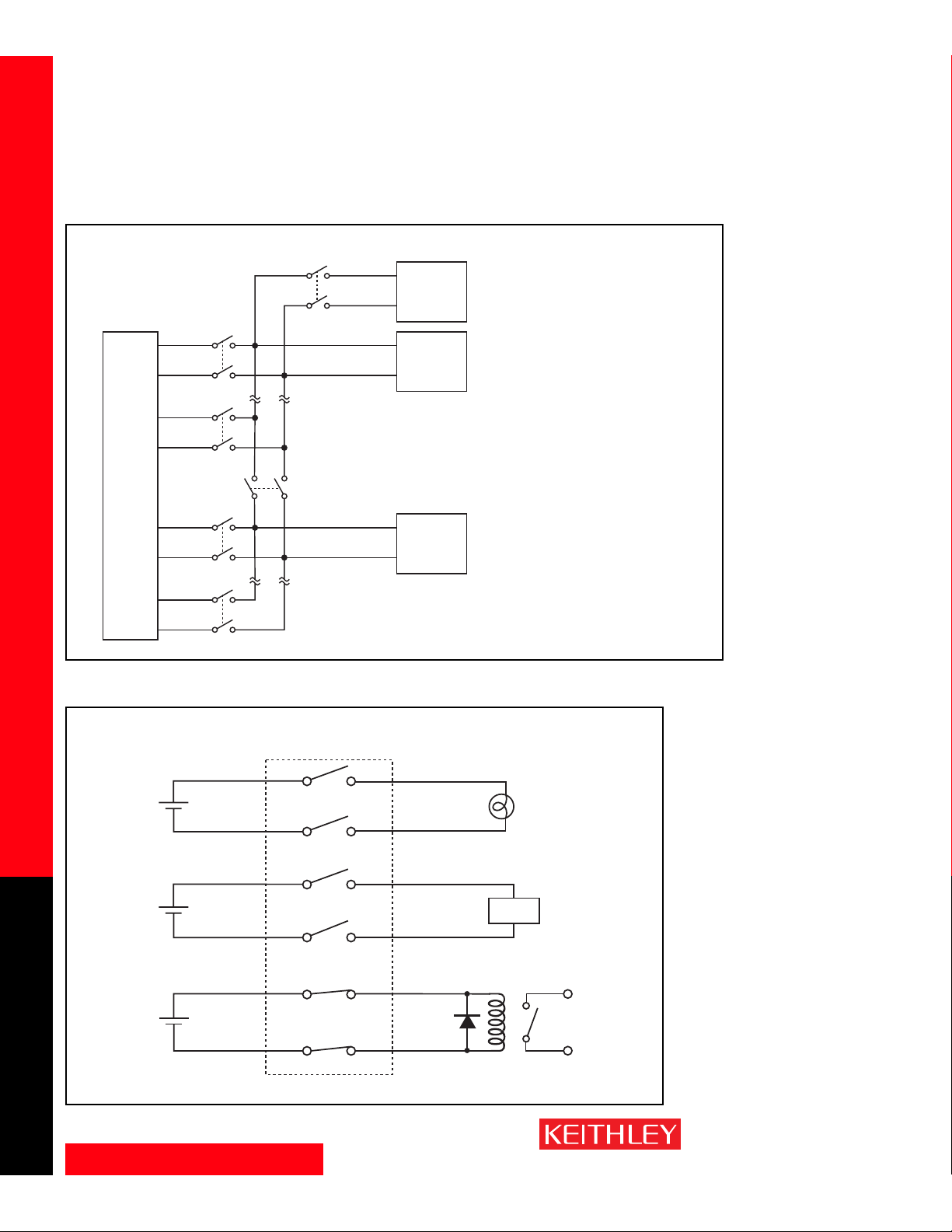
www.keithley.com
1.888.KEITHLEY (U.S. only)
A GREATER MEASURE OF CONFIDENCE
System Configuration Examples
SWITCH/MEASURE SYSTEMS
38
Integra Series Multimeter/Switch Systems
Using internal DMM and external instruments
Typical connections—indicator lamps, alarm, and relay
7705 Configuration Examples
7708 Configuration Examples (continued)
HI
Internal
DMM
LO
HI
Scope
LO
See Model 7708 specifications.
Channel 43 .....Open
Channel 44 .....Open
Channel 45 .....Closed
Ch. 1
Ch. 20
Ch. 45
Card Input
.
.
.
DUT
Ch. 43
Ch. 21
.
.
.
Ch. 40
IN 1
5V
IN 2
IN 3
12V
IN 4
Card Sense
Model 7705
Ch. 1
Ch. 2
Ch. 3
Ch. 4
HI
LO
Counter
OUT 1
OUT 2
OUT 3
OUT 4
NOTE: This configuration example
can be duplicated with the
7700, 7701, 7702, 7703,
7706, 7707, and 7708
modules. See module
specifications for their
channel configurations.
Indicator
Lamp
Alarm
IN 5
30V
IN 6
Ch. 5
Ch. 6
Equivalent Circuit
OUT 5
OUT 6
Relay
Page 39
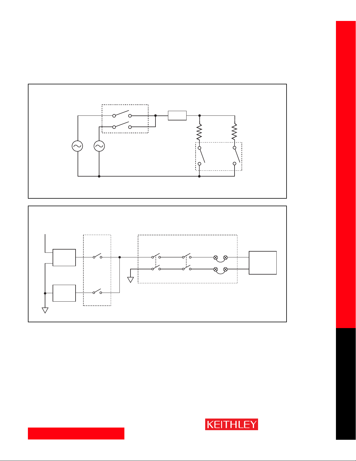
www.keithley.com
1.888.KEITHLEY (U.S. only)
A GREATER MEASURE OF CONFIDENCE
System Configuration Examples
SWITCH/MEASURE SYSTEMS
39
Integra Series Multimeter/Switch Systems
Variable AC line/load test connections
7705 Configuration Examples (continued)
Single Pole (Single Point Ground) Switching Example
Using the 7705 for independent switching and the 7701 to bring measurement of DUT to internal DMM
of 2750
Model 7705
AC
Source
HI
IN 1
IN 2
AC
Source
LO
Source is impedance limited from mains (Safety Category I signals).
OUT 1
OUT 2
CAUTION: Maximum switch current is 2A.
DUT
Model 7705
10%
Load
Resistor
IN 3
OUT 3
IN 4
OUT 4
90%
Load
Resistor
+5V
7705
7701
Screw
Terminals
DUT 1
.
.
.
Ch. 1
.
.
.
HI
LO
Ch. 1
Ch. 35
Internal
DMM
DUT 40
Ch. 40
See Model 7701 specifications.
Channel 33 .....Closed
Channel 34 .....Closed
Channel 35 .....Closed
Page 40
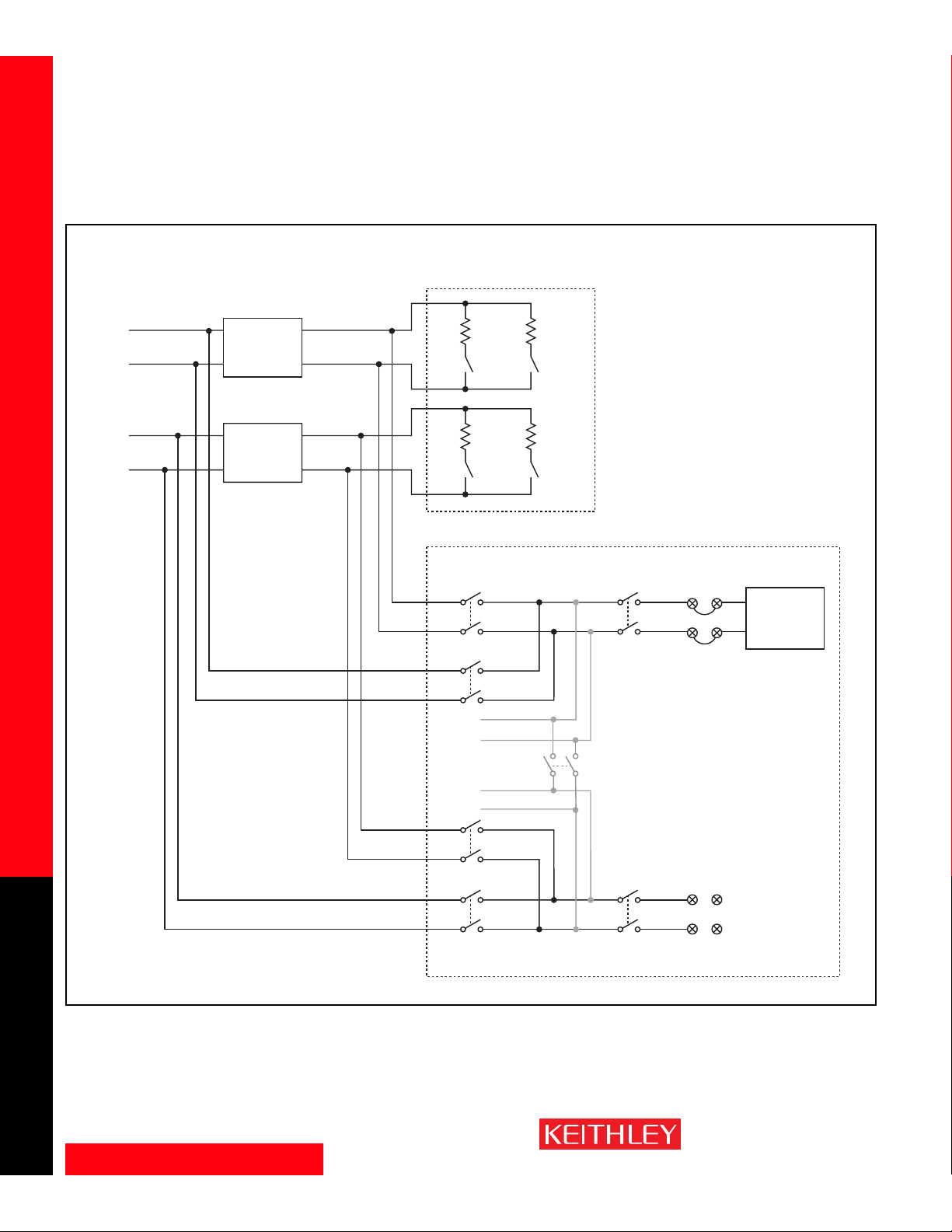
www.keithley.com
1.888.KEITHLEY (U.S. only)
A GREATER MEASURE OF CONFIDENCE
System Configuration Examples
SWITCH/MEASURE SYSTEMS
40
Integra Series Multimeter/Switch Systems
7705 independent switch and 7701 multiplexer example
7705 Configuration Examples (continued)
7705
+
–
Input
Power
+
–
48VDC
48VDC
DUT 1
DC to DC
Converter
.
.
.
DUT 16
DC to DC
Converter
Output
Output
7701
HI
LO
HI
LO
HI
LO
HI
LO
Ch. 1 Ch. 2
Ch. 31 Ch. 32
Ch. 1
Ch. 2
.
.
.
Ch. 16
Ch. 33
.
Ch. 17
.
.
Ch. 31
Ch. 32
Screw
Te rm inals
HI
Ch. 35
LO
See Model 7701 specifications.
Channel 33 .....Closed
Channel 34 .....Open
Channel 35 .....Closed
Screw
Te rm inals
HI
Ch. 34
LO
Chs. 1–32
To Internal
DMM
Page 41
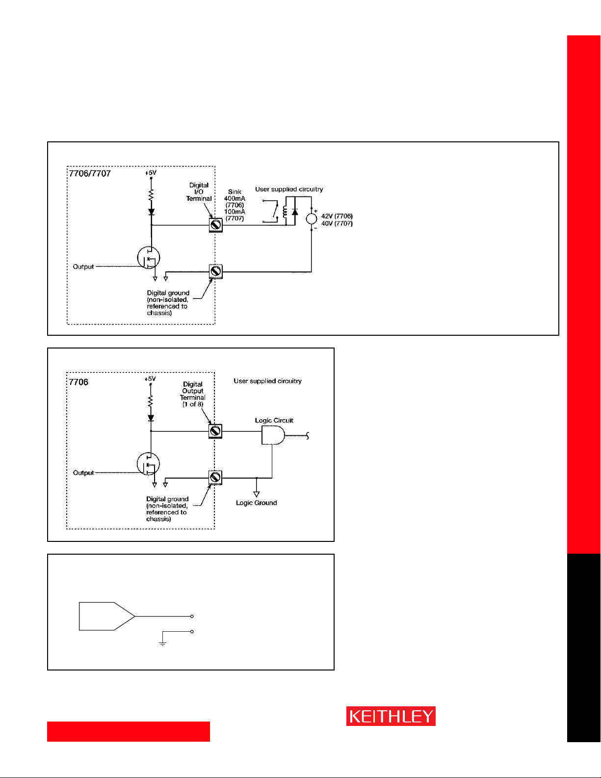
www.keithley.com
1.888.KEITHLEY (U.S. only)
A GREATER MEASURE OF CONFIDENCE
System Configuration Examples
SWITCH/MEASURE SYSTEMS
41
Integra Series Multimeter/Switch Systems
Analog Output and Digital I/O Examples
Typical digital output w/external power supply
Typical digital output (no external power supply)
Digital Output
The 7706 module has two non-isolated 8-bit output
ports that can be used for outputting digital patterns. The two ports can be combined to output a
single 16-bit word or a dual 8-bit byte. A simplified
diagram of a single output bit is shown here.
The 7707 module has four non-isolated 8-bit
input/output ports that can be used for outputting
digital patterns. The two ports can be combined to
output a 16-bit word, or dual or quad 8-bit bytes.
The 7707 can also be configured (in blocks of 8) as
digital inputs.
5mA max.
±12V
(16-bit resolution)
V
OUT
V
O
Output Common
(non-isolated,
instrument to chassis)
7706 analog output
NOTE: The 7706 module
has two ±12V analog
output channels.
Page 42
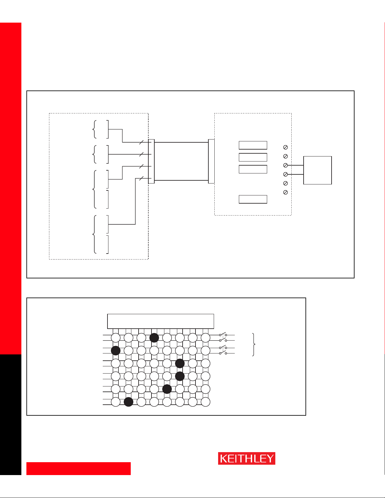
www.keithley.com
1.888.KEITHLEY (U.S. only)
A GREATER MEASURE OF CONFIDENCE
System Configuration Examples
SWITCH/MEASURE SYSTEMS
42
Integra Series Multimeter/Switch Systems
Dig. I/O Ch. 13
1
.
.
.
4
5
.
.
.
8
Available
Dig. I/O Ch. 14
1
.
.
.
4
5
.
.
.
8
Available
Dig. I/O Ch. 12
1
.
.
.
8
Dig. I/O Ch. 11
1
.
.
.
8
4
4
8
8
7707 Digital I/O
DB-50
50-Pin
Card Edge
Cable
SSR1
SSR2
SSR3
SSR24
.
.
.
Industry Standard PB-24SM
24 SSR Baseboard
Optically
isolated
User
Supplied
Switch or
Sense
.
.
.
.
.
.
Output Relays: SM-ODC5, SM-ODC5A,
SM-OAC5, SM-OAC5A,
SM-OAC5R
Input Relays: SM-IDC5, SM-IAC5,
SM-IAC5A
CAUTION: Adequate insulation barriers must be used on PB-24SM and cable for systems with >42V.
The 7709 Matrix Module can connect any combination of six differential channels of instrumentation to any combination of eight
differential DUT channels. The instrumentation can be the Integra system’s internal DMM or external equipment (AC and DC
sources, internal or external meters, oscilloscopes, etc.) This matrix configuration allows wide flexibility for complex test systems.
Matrix Configuration Example
7709 6x8 Matrix configuration example
Connecting the Model 7707 Digital I/O module to industry standard solid-state relays (SSRs) to switch high VA (up to 980VA).
Analog Output and Digital I/O Examples (continued)
DUT
12V DC Source
Scope
Counter
Signal Generator
5V DC Source
Input
To Integra
Series
Page 43
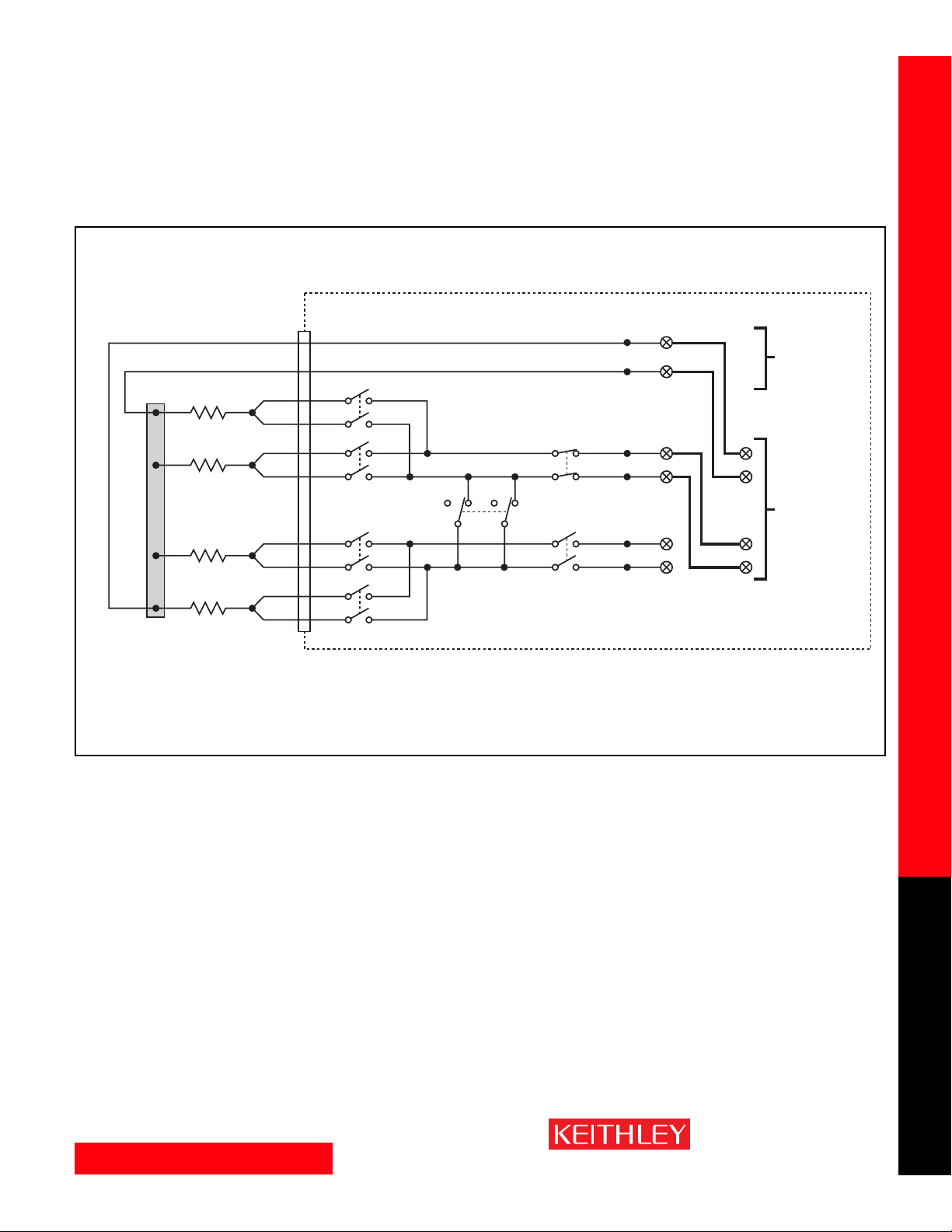
www.keithley.com
1.888.KEITHLEY (U.S. only)
A GREATER MEASURE OF CONFIDENCE
System Configuration Examples
SWITCH/MEASURE SYSTEMS
43
Integra Series Multimeter/Switch Systems
DUT1
DUT2
DUT3
DUT4
DMM Input HI
DMM Sense HI
*Common Side Bus
D-Sub
Connectors
**Ch. 33
(Open)
Ch. 35
Ch. 34
User
Installed
Jumpers
7701
User
Configurable
Screw
Terminals
2750
DMM
*NOTE: Common side connections must be made carefully to eliminate all lead
resistance from the 4-wire ohms measurement. The common side bus
should be a single wire or bus bar that connects the HI side of all the
DUTs. DMM Input HI should be connected to one end of the common
side bus and DMM Sense HI should be connected to the other end.
**NOTE: Refer to ROUTE:MULT
section of the 2700, 2701,
or 2750 manual for more
information.
Sense HI
Input HIInput HI
Sense LO
Input LO
7701 Configuration Example
7701 32-Channel common-side
4-wire Ohms configuration example
Page 44

SWITCH/MEASURE SYSTEMS
Integra Series Multimeter/Switch Systems
Keithley Instruments, Inc. 28775 Aurora Road • Cleveland, Ohio 44139 • 440-248-0400 • Fax: 440-248-6168
1-888-KEITHLEY (534-8453) www.keithley.com
© Copyright 2002 Keithley Instruments, Inc. No. 2393
Printed in the U.S.A. 80240K
 Loading...