

Page 1

Number 2378
Testing Dual Airbag Inflators and Modules
with the Model 2790 SourceMeter
®
Switch System
Application Note
Series
Introduction
A typical airbag inflator is a two-terminal device in a metal
housing and is used to initiate the deployment of the bag in an
automobile crash. Modern passenger restraint systems incorporate a dual inflator, which allows for variable inflation rates,
depending on the speed of the vehicle crash. One inflator is used
to deploy the bag for low speed scenarios; the other is used for
higher speed collisions.
The pyrotechnic device that actually triggers the gas discharge,
which inflates the airbag, is called an initiator. The resistance of
the initiator is a valid indication of a good device. Testing the
initiator is much like testing a fuse; if too high a current is used,
the fuse will open up and must be scrapped. For an initiator, the
test current must be kept below some specified level to prevent
activating the inflator prematurely, which would not only destroy
the DUT, but also presents a potential hazard. An initiator must
be electrically isolated from the inflator housing because excessive leakage current between the housing and the initiator can
prevent proper operation of the device. Consequently, an airbag
module requires two resistance measurements. One test (for the
initiator) measures a relatively low resistance using a limited test
current; the other test (for isolation) measures a relatively high
resistance using a moderately high voltage.
Another Keithley Application Note (Number 2194) describes an
airbag inflator test system based on Keithley’s Model 2410
SourceMeter and Model 7001/7002 Switch Systems. The Model
2790 system described here combines all of the switch, source,
and measure functions required for high throughput testing of the
necessary electrical characteristics of an airbag assembly in a
single instrument.
Test Description
Bridgewire Test
The airbag inflator has two terminals connected to the initiator
or, as it is commonly called, the bridgewire. The bridgewire is
coated with a primer that ignites when sufficient current passes
through the wire. Dual inflators have two bridgewires and each
wire is tested separately. The resistance of a bridgewire is
typically about 2Ω. The bridgewire is tested by sourcing a current through it and measuring the resulting voltage drop across it.
The resistance of the bridgewire is calculated using Ohm’s Law.
To avoid unintended ignition, the level of test current applied is
typically 50mA or less; therefore, the voltage to be measured is
100mV or less. A four-wire connection must be used to ensure
reasonable accuracy for this test. For more information, refer to
the section titled “Lead Resistance.”
Insulation Resistance (HIPOT) Test
The insulation resistance between each of the initiators and the
housing must be verified. Typical specifications for the insulation resistance range from 10MΩ to 100MΩ minimum. This test
is performed by applying a voltage between one of the leads of
each bridgewire and the housing, and measuring the resulting
current. Ohm’s Law is used to calculate the insulation resistance.
The test voltage is typically 500V; therefore, the current to be
measured is 50µA or less.
Shunt Bar (Shorting Clip) Test
To prevent accidental ignition due to static discharge while the
device is being handled or installed in the vehicle, a shunt bar or
shorting clip is typically installed across the inflator terminals.
The shunt must be opened or removed to test the bridgewire
properly, but it can be in place during the HIPOT test. It is common practice to measure the resistance of the installed shunt bar,
which is typically 10–100mΩ. The test current used to measure
the shunt bar should be no more than 50mA so that a defective
shunt bar will not result in ignition. Again, a four-wire connection must be used when making this measurement. Sometimes, it
is preferable to make this measurement under dry circuit conditions to avoid penetrating any oxides that may develop on the
contact surfaces of the shunt. If the test breaks down the oxide
layer, the measured resistance could be lower than what actually
exists in normal usage. Dry circuit testing requires that the voltage developed across the DUT be limited to 20mV or less. The
shunt bar is often tested several times during an inflator test
sequence: at the start to verify that it is functional, prior to the
HIPOT test to ensure the bridgewire is protected, and at the end
of the sequence to verify that it is properly installed and that the
inflator is safe to handle.
Contact Verification
To perform the insulation resistance test, contact must be made
to the airbag inflator housing as described previously. If the test
fixture does not make contact with the housing and the test is
performed, the measured resistance will be that of an open circuit rather than the true insulation resistance. Both good and bad
contact can produce passing results, but the open circuit result is
clearly invalid. Two contact points are used to verify that contact
is being made with the metal housing. The resistance between
these two contact points is measured. If the result is a compara-
Page 2
tively low value, then it is generally safe to assume proper
contact has been made.
Test System Description
The Model 2790 SourceMeter®Switch System with a single
Model 7751 plug-in module is capable of making all of the
measurements outlined in this note. The 2790 mainframe is a
full-featured 61⁄2-digit DMM with two rear slots for plug-in modules. Compatible modules add switching for signal routing, as
well as additional source and measure capabilities. Although this
note focuses on using the 7751 module for inflator testing, two
other modules are available for added flexibility. The Model
7752 module is identical to the 7751, except that it does not
include the high voltage source and current-to-voltage converter,
and the Model 7702 is a general purpose 40-channel multiplexer.
The Model 7751 module includes programmable DC voltage
(50–500V) and current (0–50mA) sources as well as relay
switching. Four banks of two-pole relays provide a sufficient
number of terminals to connect two single inflator units or one
dual inflator unit to the 2790 for test. The mainframe will
accommodate two plug-in modules, so a single 2790 system can
be connected to two test stands and be used to test two dual
inflator airbag modules. Parallel testing in the form of “voltage
soak with one card, measure with the other” is possible for both
single and double test stand configurations. The current-tovoltage converter on the 7751 module is used with the voltage
source to measure the insulation resistance. It can be used to
measure currents from 0–50µA. The 7751’s switch matrix simplifies implementing the contact verification tests discussed previously and allows the DMM to verify test voltages and currents
for increased measurement reliability. Safety related design features that provide added protection against accidental detonation
include low energy sources, a hardware source interlock, and
programmable shunts that can be used in conjunction with an
inflator’s shunt bar. These features are discussed in detail in the
section titled “Test System Safety.”
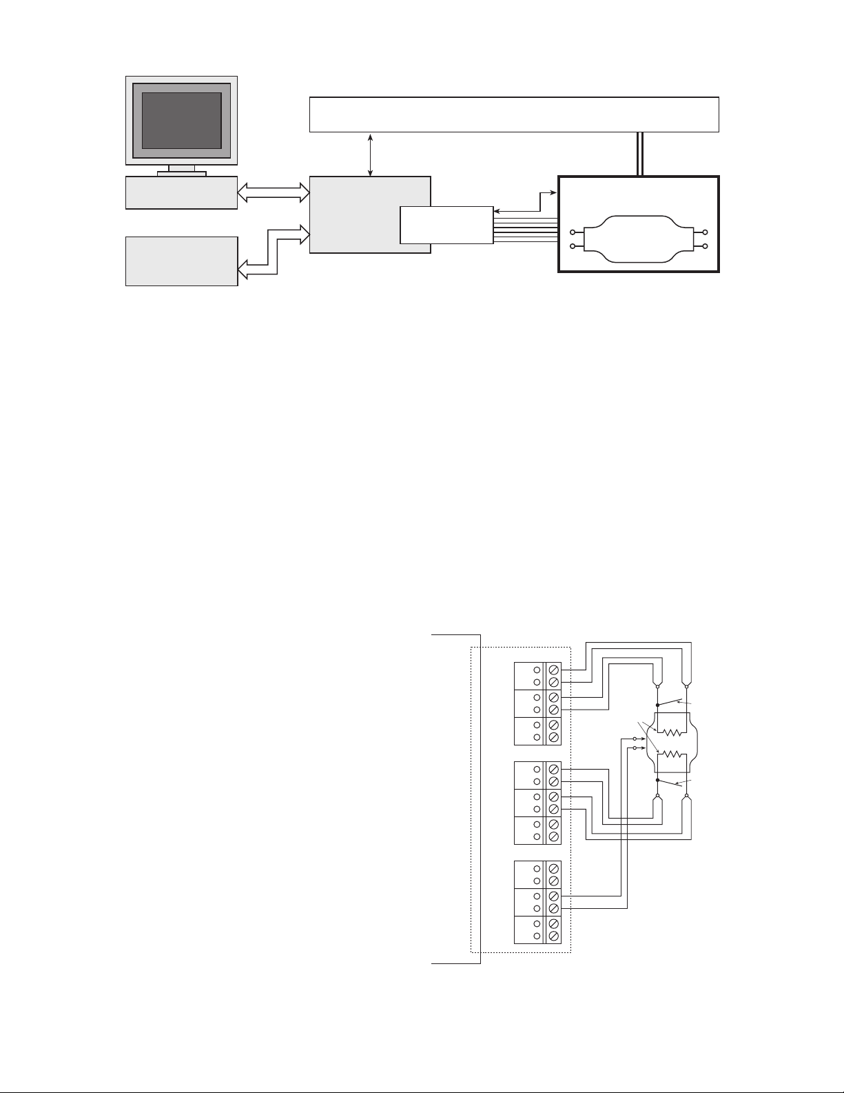
Figure 1 illustrates a typical hardware configuration for an
airbag inflator test system using a Model 2790. In automated
manufacturing systems, programmable logic controllers (PLCs)
are often used for process control, rather than PCs. Most of
today’s PLCs do not offer GPIB modules, so system control
must be done over the serial (RS-232) bus. The Model 2790 has
both GPIB and RS-232 interfaces, so it’s suitable for use with
both PC and PLC controlled test systems.
All of the switching required to connect the sources and
measurement circuitry to the inflator is contained on the 7751
module. Cabling from the test stand is connected to the 7751
module via screw terminals. Figure 2 shows a typical connection
scheme for testing a dual inflator. Relay channels 1 through 9
connect signals to and from the various parts of the inflator
DUT, depending on which test is being performed. Channels 10
through 12 (Bank 4) are also available for connecting to the
Device Handler
Figure 1. Typical Dual Inflator Test System
Figure 2. Typical Connections Between 7751 and a Dual Inflator Module
Digital I/O
(Handler Control)
PC with
IEEE-488 Interface
OR
GPIB
RS-232
Model 2790
SourceMeter
Switch System
PLC
Mechanical
Connection
Interlock
Test Fixture/
Operator Safety Shield
7751 Module
Inflator
System
Under Test
Cabling
7751 Module
2790
Mainframe
SRC HI
SEN HI
SRC LO
SEN LO
SRC HI
SEN HI
SRC LO
SEN LO
SRC HI
SEN HI
SRC LO
SEN LO
Bank 1
Ch 1
Ch 2
A1
Ch 3
B1
Bank 2
Ch 4
Ch 5
A2
Ch 6
B2
Bank 3
Ch 7
Ch 8
A3
Ch 9
B3
Housing
Connections
Bridgewires
Bridgewire
Connections
Shunt Bar (Shorting Clip)
A
Dual Stage
B
Inflator
Shunt Bar (Shorting Clip)
Bridgewire
Connections
Page 3
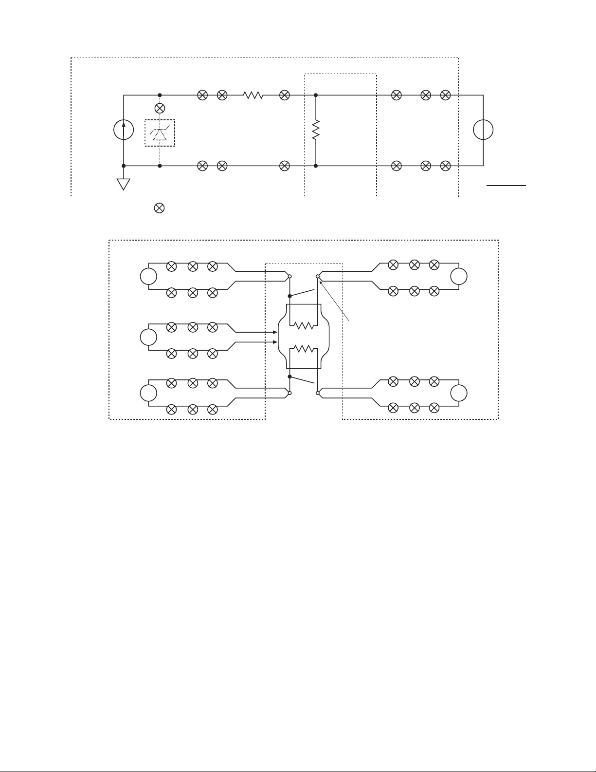
DUT, but they are not used in this example. Additional relay
channels control the interconnection of the DUT channels and
the voltage and current sources, the voltage-to-current converter,
and the DMM. The terminal labels shown in this figure (and present on the card) reflect the typical functional connection in a
four-wire resistance measurement, but because of the remarkable
flexibility of this module, the actual internal connections will
vary, depending on the signal routings chosen. For example, the
leads connected to Ch 8 in the figure are from the two connection points on the housing. For contact verification, these terminals are routed to the INPUT HI and LO terminals of the 2790
DMM so that a two-wire resistance measurement can verify that
both contacts are electrically connected to the housing.
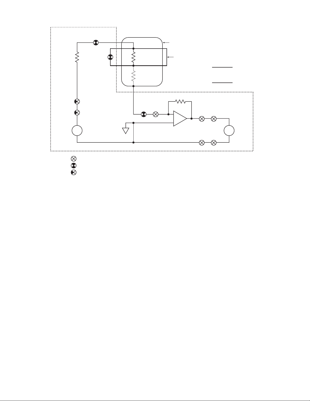
Given the connections shown in Figure 2, Figures 3
through 5 show the test circuits for the various tests that have
been addressed. Figure 3 shows the circuit for testing either the
bridgewire or the shunt. Open relay channel 22 and close channels 1, 2, and 21 to select the current source and connect it to
either bridgewire A or shunt A (if it is in place). Channel 22 is a
Form C relay, and the current source is selected when it is in the
normally open position. The DMM is connected across the
bridgewire or the shunt by closing relay channels 1, 2, 17, and
18. To test bridgewire B and shunt B, close channels 4 and 5
instead of 1 and 2. This is a four-wire resistance measurement
configuration, which ensures that the resistance of the connecting
leads is not included in the measured value of the bridgewire or
shunt resistance. The resistance calculation shown in the figure
can be performed internally by the 2790 by selecting the
S1IOHMS math function (assuming the module is in Slot 1). The
calculation uses the programmed level of the current source. It is
possible to close a different group of relays and connect the
DMM across the 1Ω resistor and measure the voltage drop. The
measured voltage can be used to verify that the programmed current is actually being sourced. This measured current can also be
used to calculate the DUT resistance manually. As mentioned
previously, it is possible to connect a 20mV dry circuit clamp
across the DUT. This feature, which is enabled by closing channel 24, can be used to prevent the breakdown of oxide layers on
the shunt bar and/or to reduce the possibility of accidental detonation further. If the clamp is used, the current source output is
limited to a maximum of 1mA.
Figure 4 shows the test setup for performing contact verifi-
cation. The wiring diagram in Figure 2 shows two leads connected to each bridgewire (or shunt) terminal and to the housing.
Keithley 7751 or 7752
Figure 3. Circuit Configuration for Testing Bridgewire and Shunt Bar
Figure 4. Circuit Configurations for Contact Verification (Housing and Four-Wire Source/Sense Connections)
1Ω21 1 or 4*22
1 or 4*
1817
24
I
*
SOURCE
Optional 20mV
Dry Circuit Clamp
21 2 or 5*22
= Closed relay contacts; multiple contacts indicate 2-pole relays
Keithley 7751 or 7752
2790
DMM
2790
DMM
2790
DMM
Ω2
Ω2
Ω2
18
15
LO
Bank 1
215
LO
LO
Bank 3
818
LO
HI
Bank 2
41418
HI
A
B
Bridgewire
or Shunt Bar
Under Test
(R)
HI
Bank 1
HI
Contact Point
(1 of 5)
LO
Bank 2
LO
2 or 5*
Input HI
2790
V
DMM
R =
2790
DMM
2790
DMM
Input LO
V
MEASURED
I
SOURCE
1817
18141
Ω2
18155
Ω2
Page 4
By closing the different combinations of relays identified in
Figure 4, it is possible to perform a two-wire ohms measurement
on each pair of leads and verify good electrical contact. If both
wires are electrically connected together, the resulting measurement can range from approximately 12Ω to several tens of ohms,
depending on the type and length of the connecting cables. The
minimum of approximately 12Ω is due to the internal circuitry
of the switch modules. If the measured resistance is significantly
higher, then it is likely that one or both of the leads are not
contacting the terminals or housing.
Figure 5 shows the test circuit for measuring the insulation
resistance. Close relay channels 1, 21, and 22 to select the voltage source and connect it to one terminal of bridgewire A. The
voltage source is selected when the channel 22 relay is in the
normally closed position. Given that the resistance of a good
bridgewire is much less than the leakage resistance being measured, it is necessary to perform this test at only one of the
bridgewire terminals. Close relay channels 8 and 23 to connect
the housing to the current-to-voltage converter (I/V Amplifier).
Finally, connect the output of the current-to-voltage converter to
the DMM by closing relay channels 16 and 18. To measure the
insulation resistance between bridgewire B and the housing,
close channel 4 instead of 1. A two-wire resistance measurement
configuration can be used in this case because the resistance of
the test leads is insignificant compared to the leakage resistance.
The resistance calculation shown in the figure can be performed
internally by the 2790 by selecting the S1VOHMS math function
(assuming the module is in Slot 1). The current-to-voltage con-
verter is an inverting amplifier, so a positive current will produce
a negative output voltage. The minus sign in the calculation
ensures that positive resistances are displayed. Note that the calculation uses the programmed level of the voltage source. It is
possible to close a different group of relays to connect the DMM
across the voltage source and measure its output to verify that
the programmed voltage is actually being applied to the DUT.
This measured voltage can also be used to calculate the leakage
resistance manually.
Figure 5 shows the shunt bar (shorting clip) connected
across the bridgewire. Some manufacturers prefer measuring the
insulation resistance when the shunt bar is connected because it
is almost impossible to inflate the airbag with the short in place.
The 7751 module has four relay-selectable shunts (channels 3, 6,
9, and 12) that can be used along with the inflator shunt bars for
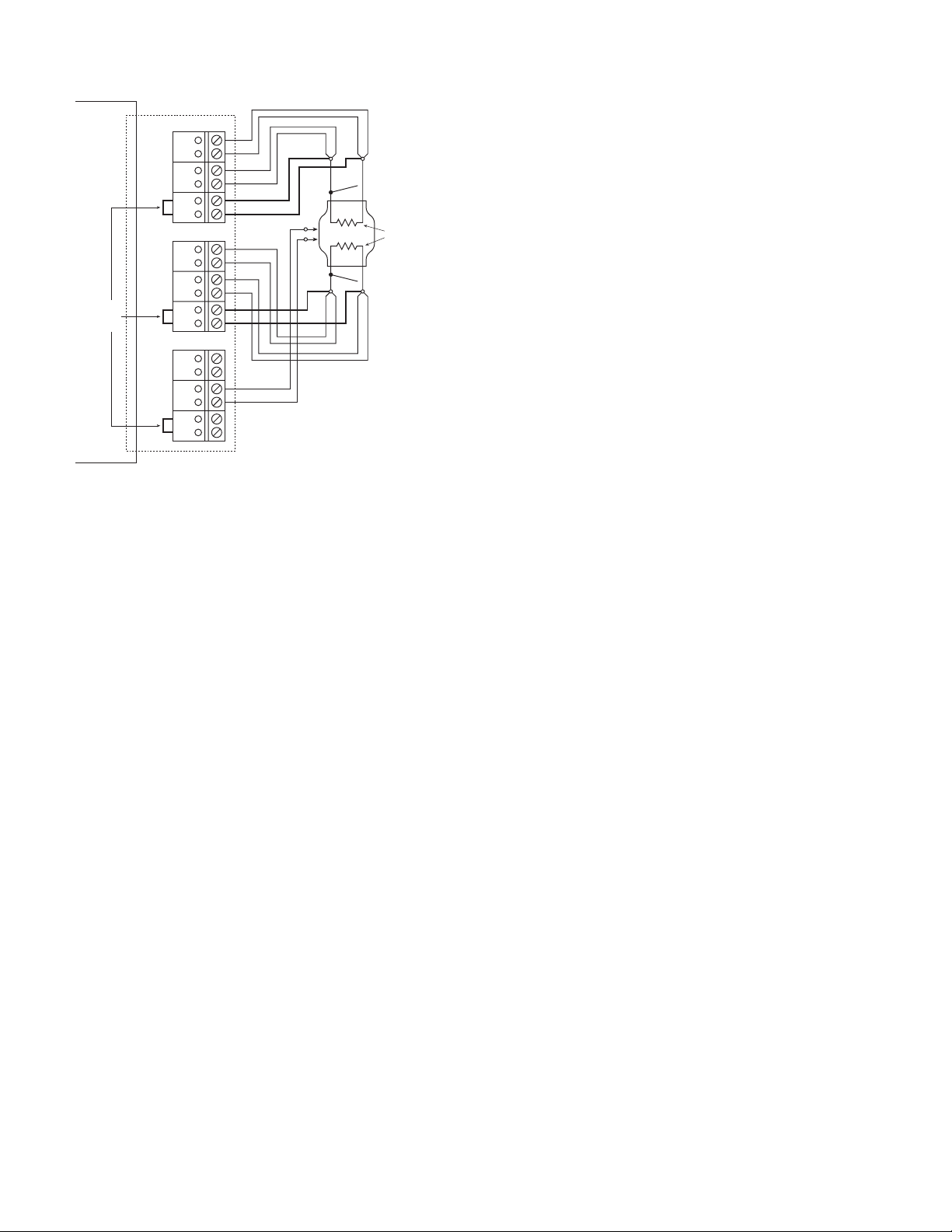
added reliability. Figure 6 shows one possible connection
scheme for using the 7751 module’s integral shunts. As depicted
in Figure 5, closing relay channels 3 and/or 6 connects the addi-
tional shunts across bridgewires A and/or B during the insulation
test.
Test System Safety
When designing an inflator test system, the user should note that
airbag inflators are explosive and therefore dangerous. Even if
the test system is designed with sufficient safeguards, a defective
device under test could detonate under normal testing conditions.
Test system designers must be aware of the hazards involved
Keithley 7751
Figure 5. Circuit Configuration for Testing Insulation Resistance
1Ω
21
22
V
SOURCE
(7751)
+
–
= Closed relay contacts; multiple contacts indicate 2-pole relays
= Closed relay contacts; 2-pole relays with poles connected together for this test
= Closed relay contacts; 2-pole relays with one pole unused for this test
1 or 4*
3 and 6*
Internal
Shunts
Inflator
Bridgewire
Insulation
Resistance
Under Test
(R
)
HIPOT
238
Inflator Housing
Shunt Bar (Shorting Clip)
R
HIPOT
R
F
200kΩ
–
+
I/V Amplifier
(7751)
16 18
16 18
=
=
-V
SOURCE
V
MEASURED
-V
SOURCE
V
MEASURED
x R
x 200kΩ
Input HI
2790
V
DMM
Input LO
F
Page 5
with this application and design the test fixtures such that sufficient protection is available for themselves, operators, or maintenance personnel in the event of an unintentional detonation of
an inflator. Sufficient protection must be provided to personnel
against any hazardous voltages that may be present as well. It is
also the responsibility of system designers to make sure that all
personnel are trained in the safe use of the test system.
Keithley has incorporated many design features in the 2790
SourceMeter Switch System and the 7751 module that make this
inflator test system inherently less likely to cause an initiator detonation than previous test solutions. Significant steps have been
taken to limit the power applied to the device under test, even
under single fault conditions (e.g., programming error or test
instrument failure). Design features that enhance the reliability of
the 2790 system include a low energy, high voltage source, a low
voltage compliance (5.5V) current source, and automatic cable
discharge circuitry. A hardware source interlock is also available
and is discussed in the section titled “Methods and Techniques/
Handler Interface.” The high voltage source cannot be programmed to output more than 500V, and at this level, internal
impedances limit the current output to less than 1mA under short
circuit conditions. Even under single fault conditions, the voltage
is clamped at 600V and the steady state current is limited to less
than 2mA.
Capacitance between signal paths on the 7751 module and
in cables connecting the inflator to the module can store a charge
from the voltage source. Whenever the voltage source is disconnected from the switch matrix by opening channel 22, 100kΩ
shunts are automatically connected between the Source HI and
LO lines and the Sense HI and LO lines for 5ms to bleed off any
residual charge. The discharge circuitry can also be controlled
directly to allow the user to discharge the cables for more than
5ms, or at other times during the test sequence. NOTE: In order
to discharge any connecting cables, the relays connected to the
cables should not be opened until after the voltage source has
been disconnected from the signal lines. Using the “OPEN
ALL CHANNELS” command from the front panel or under
remote control automatically opens Channel 21 and then
Channel 22 five milliseconds before opening any other channels. Caution: Do not connect the voltage source HI to earth
ground. Doing so will effectively connect an internal capacitance of 1nF across the Vsource HI and LO, which could
cause the capacitor to be discharged across the DUT if proper
precautions are not taken.
The current source cannot be programmed to output more
than 50mA. The open circuit voltage of this source is 5.5V.
Under single fault conditions, the output current is limited first
by redundant active current limiters and ultimately by dual
62mA fuses. The fast response of the active limiters minimizes
the duration of any initial transients. As mentioned previously, a
dry circuit clamp can be connected across the output of the current source to limit the DUT voltage to 20mV.
NOTE: Operators and maintenance personnel must be protected from injury under fault conditions (e.g., software error,
controller error, instrument failure, system overloads). Use
appropriate guards, shields, and insulators on external connections to protect any user or maintenance personnel from risk of
electric shock or mechanical injury.
Methods and Techniques
Handler Interface – Digital I/O
The 2790’s built-in digital interface is capable of controlling the
device handler equipment directly. The digital interface connector contains five TTL-compatible digital outputs and two inputs,
as well as connections for externally powered relays and ground.
The five outputs provide test pass/fail notification. Two high
limits and two low limits can be defined globally for any DMM
measurement. They can also be defined separately for each
measurement channel. This last feature does not apply to the
7751 and 7752 modules because none of the channels are
defined strictly as measurement channels. It is possible, however,
to assign limits on a per channel basis if the available 7702 module is used. Each limit is tied to a different digital output. The
fifth digital output is a master limit, which is the logical “OR” of
the other four lines. The logic sense of the five digital outputs
can be set to either high true or low true. The outputs can be
used to control external relays with coil voltages from 5V to
33V. Each digital output has an internal flyback diode for protection when switching inductive loads. Connection to the diodes is
via Pin 7 of the digital I/O connector.
The two digital inputs both relate to external triggers. One
input is for an external trigger and the other is a trigger interlock.
Applying a TTL low (0V) to the trigger interlock pin or shorting
Figure 6. Typical Connections for Using 7751 Shunts During Inflato Testing
2790
Mainframe
Integral
Shunts
7751 Module
SRC HI
SEN HI
SRC LO
SEN LO
A1
B1
SRC HI
SEN HI
SRC LO
SEN LO
A2
B2
SRC HI
SEN HI
SRC LO
SEN LO
A3
B3
Ch 1
Ch 2
Ch 3
Ch 4
Ch 5
Ch 6
Ch 7
Ch 8
Ch 9
Bank 1
Bank 2
Bank 3
Shunt Bar (Shorting Clip)
Dual Stage
Inflator
A
Bridgewires
B
Shunt Bar (Shorting Clip)
Page 6

it to ground locks out or disables external triggers. Applying a
TTL high (5V) to the trigger interlock pin, or leaving it open
circuited, enables external triggers. For example, when controlling a scan using external triggers, this trigger interlock feature
can be used to prevent a scan from proceeding if a safety shield
is open by having the handler provide the appropriate signal.
Handler Interface – Trigger Link
The Trigger Link connector on the 2790 has one TTL-compatible
digital input, one digital output, and two ground lines. The input
is for an external trigger. It is the same as the trigger input of the
digital I/O connector. The output provides a trigger signal upon
completion of a 2790 DMM measurement and can be used to
signal a handler that a test is finished.
Handler Interface – 7751/7752 Interlock
The 7751 and 7752 modules have their own interlock circuits,
which provide a more effective interlock for use with safety
shields. Open circuiting the interlock terminals opens relay channels 18, 19, and 21 on the 7751 and 7752 modules and prevents
them from being closed. The current and voltage (7751 only)
sources are disconnected from the signal lines, as is the 2790
measurement backplane. To close these channels, a short circuit
must be applied to the interlock terminals. Connecting a switch
to the 7751/7752 interlock that opens the interlock circuit whenever the handler’s safety shield is opened or closes the interlock
circuit when the safety shield is closed is an appropriate method
for using this feature.
Basic Programming Guidelines
The following sections provide the remote programming commands needed to configure the 2790 and perform all of the tests
described in this application note. The tests are implemented for
the connection scheme shown in Figure 6. It is assumed that the
7751 module is in Slot 1 of the 2790 mainframe. The internal
shunts on the 7751 module are always connected unless a particular bridgewire or shunt bar is being tested. Each section contains all of the configuration commands necessary to perform
that particular test. If upon completion of a test the instrument is
already configured properly for the next test, then clearly it is not
necessary to send commands that do not change any settings.
Such commands are included here only so each test can be performed independent of the others.
The command strings are sent to the Model 2790 via either
the GPIB or RS-232 communication interface to execute an
inflator test. Use the 2790’s front panel controls to select the bus
the instrument will use. Once the communication protocol is
selected, it is saved as a default in nonvolatile memory until it is
changed again. To set the protocol using the front panel controls,
press and release SHIFT and then press either GPIB or RS-232.
If the selected interface is OFF, use the left/right arrow keys to
select the ON/OFF setting (flashes when selected). Use the
up/down range keys to change the setting to ON and then press
ENTER. Use the same keys to change communication parameters like GPIB address or RS-232 baud rate, pressing ENTER to
accept each setting. Be sure the INPUTS FRONT/REAR switch
is set to REAR (pushed in) to route signals through the plug-in
module to the DMM.
Reset Hardware and set global data format
Send 2790 (“*RST”) ‘ Reset instrument and put in one-shot measurement mode
Send 2790 (“FORM:ELEM READ”) ‘ Send only the reading values to the PC when queried;
Configure and perform Contact Verification
Note: Relays identified in channel list are closed sequentially in the order they appear in the list. Typically, only contact with the
housing is verified, but the 2790 makes checking the complete system a simple process.
Send 2790 (“ROUT:MULT:CLOS (@103,106)”) ‘ Connect internal shunts across DUT
Send 2790 (“SENS:FUNC ‘RES’”) ‘ Set DMM to 2-wire Ohms
Send 2790 (“SENS:RES:RANG 100”) ‘ Set resistance range to 100 Ohms
Send 2790 (“SENS:RES:NPLC 1”) ‘ Set integration time to 1 power line cycle
Send 2790 (“ROUT:MULT:CLOS (@101,114,118)”) ‘ Connect Bridgewire A HI leads to DMM
Send 2790 (“READ?”) ‘ Initialize 2790 and ask for data (triggers a measurement)
Enter 2700 (Data String) ‘ Enter data into PC from Model 2790; value is a
resistance
Inspect Data for Pass/Fail – Continue if pass, take appropriate action and repeat test if fail
Send 2790 (“ROUT:MULT:OPEN (@101)”) ‘ Disconnect Bridgewire A HI leads from DMM
Send 2790 (“ROUT:MULT:CLOS (@104)”) ‘ Connect Bridgewire B HI leads to DMM
Send 2790 (“READ?”) ‘ Initialize 2790 and ask for data (triggers a measurement)
Enter 2700 (Data String) ‘ Enter data into PC from Model 2790; value is a
resistance
Inspect Data for Pass/Fail – Continue if pass, take appropriate action and repeat test if fail
Send 2790 (“ROUT:MULT:OPEN (@104,114)”) ‘ Disconnect Bridgewire B HI leads from DMM
Send 2790 (“ROUT:MULT:CLOS (@102,115)”) ‘ Connect Bridgewire A LO leads to DMM
Send 2790 (“READ?”) ‘ Initialize 2790 and ask for data (triggers a measurement)
Enter 2700 (Data String) ‘ Enter data into PC from Model 2790; value is a
resistance
Inspect Data for Pass/Fail – Continue if pass, take appropriate action and repeat test if fail
Send 2790 (“ROUT:MULT:OPEN (@102)”) ‘ Disconnect Bridgewire A LO leads from DMM
Page 7

Send 2790 (“ROUT:MULT:CLOS (@105)”) ‘ Connect Bridgewire B LO leads to DMM
Send 2790 (“READ?”) ‘ Initialize 2790 and ask for data (triggers a measurement)
Enter 2700 (Data String) ‘ Enter data into PC from Model 2790; value is a
resistance
Inspect Data for Pass/Fail – Continue if pass, take appropriate action and repeat test if fail
Send 2790 (“ROUT:MULT:OPEN (@105)”) ‘ Disconnect Bridgewire B LO leads from DMM
Send 2790 (“ROUT:MULT:CLOS (@108)”) ‘ Connect Housing LO leads to DMM
Send 2790 (“READ?”) ‘ Initialize 2790 and ask for data (triggers a measurement)
Enter 2700 (Data String) ‘ Enter data into PC from Model 2790; value is a
resistance
Inspect Data for Pass/Fail – Continue if pass, take appropriate action and repeat test if fail
Send 2790 (“ROUT:MULT:OPEN (@108,115,118)”) ‘ Disconnect Housing LO leads from DMM; internal shunts
still connected
Configure and perform Shunt Bar (Shorting Clip) tests
Note: First shunt bar tested without dry circuit, second tested with dry circuit. At end of test the internal shunts are left connected to
the DUT. Use ROUT:OPEN:ALL if going to disconnect DUT from test system. Also, selecting S1I ohms math function automatically
sets the measurement function to DC Volts and measurement range to 1V.
Send 2790 (“ROUT:MULT:CLOS (@103,106)”) ‘ Connect internal shunts across DUT
Send 2790 (“ROUT:MULT:OPEN (@122)”) ‘ Select I-source; default setting
Send 2790 (“SOUR:CURR 0.05, (@127)”) ‘ Set Current Source level to 50 mA
Send 2790 (“CALC1:FORM S1I”) ‘ Use low ohms (source I measure V) math function to
calculate resistance
Send 2790 (“SENS:VOLT:NPLC 1”) ‘ Set integration time to 1 power line cycle
Send 2790 (“CALC1:STAT ON”) ‘ Enable the math function
Send 2790 (“ROUT:MULT:CLOS (@101,102,117,118,121)”)
‘ Connect Shunt Bar A to Current Source and DMM
Send 2790 (“ROUT:MULT:OPEN (@103)”) ‘ Disconnect internal shunt from Shunt Bar A
Send 2790 (“READ?”) ‘ Initialize 2790 and ask for data (triggers a measurement)
Send 2790 (“ROUT:MULT:CLOS (@103)”) ‘ Reconnect internal shunt across Shunt Bar A
Enter 2700 (Data String) ‘ Enter data into PC from Model 2790; value is a
resistance
Inspect Data for Pass/Fail – Continue if pass, take appropriate action if fail
Send 2790 (“ROUT:MULT:OPEN (@101,102)”) ‘ Disconnect Shunt Bar A from I-source and DMM
Send 2790 (“SOUR:CURR 0.001, (@127)”) ‘ Set current source level to 1 mA for dry circuit
measurement
Send 2790 (“ROUT:MULT:CLOS (@104,105,124)”) ‘ Connect Shunt Bar B to Current Source and DMM; enable
dry circuit
Send 2790 (“ROUT:MULT:OPEN (@106)”) ‘ Disconnect internal shunt from Shunt Bar B
Send 2790 (“READ?”) ‘ Initialize 2790 and ask for data (triggers a measurement)
Send 2790 (“ROUT:MULT:CLOS (@106)”) ‘ Reconnect internal shunt across Shunt Bar A
Enter 2700 (Data String) ‘ Enter data into PC from Model 2790; value is a
resistance
Inspect Data for Pass/Fail – Continue if pass, take appropriate action if fail
Send 2790 (“ROUT:MULT:OPEN (@121,104,105,117,118,124)”)
‘ Open I-source and disconnect Shunt Bar B from DMM;
disable dry circuit
Configure and perform Bridgewire tests
Note: Test current verified prior to first bridgewire test. At end of test the internal shunts are left connected to the DUT. Use
ROUT:OPEN:ALL if going to disconnect DUT from test system.
Send 2790 (“ROUT:MULT:CLOS (@103,106)”) ‘ Connect internal shunts across DUT
Send 2790 (“ROUT:MULT:OPEN (@122)”) ‘ Select I-source; default setting
Send 2790 (“SOUR:CURR 0.05, (@127)”) ‘ Set Current Source level to 50 mA
Send 2790 (“CALC1:STAT OFF”) ‘ Disable any math functions
Send 2790 (“SENS:FUNC ‘VOLT’”) ‘ Set DMM to DC Volts
Send 2790 (“SENS:VOLT:RANG 0.1”) ‘ Set voltage range to 100 mV
Send 2790 (“SENS:VOLT:NPLC 1”) ‘ Set integration time to 1 power line cycle
Send 2790 (“ROUT:MULT:CLOS (@101,102,118,125,121)”)
‘ Connect Bridgewire A to Current Source and I-source
sense resistor to DMM
Send 2790 (“ROUT:MULT:OPEN (@103)”) ‘ Disconnect internal shunt from Bridgewire A
Send 2790 (“READ?”) ‘ Initialize 2790 and ask for data (triggers a measurement)
Send 2790 (“ROUT:MULT:CLOS (@103)”) ‘ Reconnect internal shunt across Bridgewire A
Enter 2700 (Data String) ‘ Enter data into PC from Model 2790; reading is a voltage
equal in value to test current
Inspect Data for Pass/Fail – Continue if pass, take appropriate action if fail
Send 2790 (“ROUT:MULT:OPEN (@125)”) ‘ Disconnect I-source sense resistor from DMM
Page 8

Send 2790 (“CALC1:FORM S1I”) ‘ Use low ohms (source I measure V) math function to
calculate resistance
Send 2790 (“CALC1:STAT ON”) ‘ Enable the math function
Send 2790 (“ROUT:MULT:CLOS (@117)”) ‘ Connect Bridgewire A to DMM
Send 2790 (“ROUT:MULT:OPEN (@103)”) ‘ Disconnect internal shunt from Bridgewire A
Send 2790 (“READ?”) ‘ Initialize 2790 and ask for data (triggers a measurement)
Send 2790 (“ROUT:MULT:CLOS (@103)”) ‘ Reconnect internal shunt across Bridgewire A
Enter 2700 (Data String) ‘ Enter data into PC from Model 2790; value is a
resistance
Inspect Data for Pass/Fail – Continue if pass, take appropriate action if fail
Send 2790 (“ROUT:MULT:OPEN (@101,102)”) ‘ Disconnect Bridgewire A from I-source and DMM
Send 2790 (“ROUT:MULT:CLOS (@104,105)”) ‘ Connect Bridgewire B to Current Source and I-Souce and DMM
Send 2790 (“ROUT:MULT:OPEN (@106)”) ‘ Disconnect internal shunt from Bridgewire B
Send 2790 (“READ?”) ‘ Initialize 2790 and ask for data (triggers a measurement)
Send 2790 (“ROUT:MULT:CLOS (@106)”) ‘ Connect internal shunt across Shunt Bar A
Enter 2700 (Data String) ‘ Enter data into PC from Model 2790; value is a
resistance
Inspect Data for Pass/Fail – Continue if pass, take appropriate action if fail
Send 2790 (“ROUT:MULT:OPEN (@121,104,105,117,118)”)
‘ Open I-source and disconnect Bridgewire B from DMM
Configure and perform Insulation Resistance (HIPOT) tests
Note: Test voltage verified prior to first Insulation Resistance test. At end of test the internal shunts are left connected to the DUT.
Use ROUT:OPEN:ALL if going to disconnect DUT from test system. Also, selecting S1Vohms math function automatically sets the
measurement function to DC Volts and measurement range to 10V.
Send 2790 (“ROUT:MULT:CLOS (@103,106)”) ‘ Connect internal shunts across DUT
Send 2790 (“SOUR:VOLT 500, (@128)”) ‘ Set Voltage Source level to 500 V
Wait 250 ms for V-source to settle ‘ Settling time for 50V to 500V transition
Send 2790 (“CALC1:STAT OFF”) ‘ Disable any math functions
Send 2790 (“SENS:FUNC ‘VOLT’”) ‘ Set DMM to DC Volts
Send 2790 (“SENS:VOLT:RANG 1000”) ‘ Set voltage range to 1000 V
Send 2790 (“SENS:VOLT:NPLC 1”) ‘ Set integration time to 1 power line cycle
Send 2790 (“ROUT:MULT:CLOS (@122,113,118,123,121)”)
‘ Select V-source and connect DMM across it; connection to
V-source LO is made through I-V converter
Wait approximately 50ms for V-source to settle ‘ Settling time for step change in load
Send 2790 (“READ?”) ‘ Initialize 2790 and ask for data (triggers a measurement)
Enter 2700 (Data String) ‘ Enter data into PC from Model 2790; reading is V-source
open circuit voltage (input resistance of DMM on 1000 V
range is 10 MΩ)
Inspect Data for Pass/Fail – Continue if pass, take appropriate action if fail
Send 2790 (“ROUT:MULT:OPEN (@121,122,113)”) ‘ Open 122 to deselect V-source and discharge module; other
channels disconnect V-source from DMM
Send 2790 (“CALC1:FORM S1V”) ‘ Use high ohms (source V measure I) math function to
calculate resistance
Send 2790 (“CALC1:STAT ON”) ‘ Enable the math function
Send 2790 (“TRIG:DEL 2”) ‘ Set nominal 2 sec soak time from when 2790 is
initialized until measurement is made
Send 2790 (“ROUT:MULT:CLOS (@101,108,116,122,121)”)
‘ Connect Bridgewire A HI to V-source and Housing LO to
I-V converter; connect I-V converter output to DMM
Send 2790 (“READ?”) ‘ Initialize 2790 and ask for data (triggers a measurement);
V-source settles during soak time
Enter 2700 (Data String) ‘ Enter data into PC from Model 2790; value is a
resistance
Inspect Data for Pass/Fail – Continue if pass, take appropriate action if fail
Send 2790 (“ROUT:MULT:OPEN (@121,122,101)”) ‘ Discharge module and cables; disconnect V-source and
Bridgewire A HI from test circuit
Send 2790 (“ROUT:MULT:CLOS (@104,122,121)”) ‘ Select V-source; connect V-source and Bridgewire B HI
to test circuit
Send 2790 (“READ?”) ‘ Initialize 2790 and ask for data (triggers a measurement);
V-source settles during soak time
Enter 2700 (Data String) ‘ Enter data into PC from Model 2790; value is a
resistance
Inspect Data for Pass/Fail – Continue if pass, take appropriate action if fail
Send 2790 (“ROUT:MULT:OPEN (@121,122,104,108,116,118)”)
‘ Discharge module; disconnect V-source, Bridgewire B HI,
I-V converter and DMM from test circuit
Page 9

Running the Tests
Performing the tests in the order presented in the “Basic Programming Guidelines” section is one possible approach to testing a
dual inflator air bag module. As previously mentioned, the shunt
bar tests are often performed multiple times to ensure that the
shunts are functional and properly connected. The example code
tries to show all of the various measurement capabilities that are
discussed in this note, but the need to use any of these features
depends on the specific application and test requirements. The
instrument configurations used in the example were chosen so
that the rated measurement accuracies of the 7751 module should
be achieved rather than for maximum test throughput. Several
steps can be taken if test speed is critical and noise immunity or
measurement accuracy can be traded off. The integration time for
the example measurements is set at 1 PLC (power line cycle),
which at 60Hz is 16.7ms. The integration time can be reduced by
a factor of 100 to just 0.01 PLC at the cost of reduced immunity
to power line frequency noise (see the “Noise” section under
“Typical Sources of Error.”) Other steps that can be taken to
increase speed include turning off the instrument display and
turning off the autozero function. Normally, the Model 2790 periodically measures internal voltages corresponding to offsets and
amplifier gains to help maintain stability and accuracy over time
and changes in temperature. These internal measurements take
time; therefore, turning them off can speed up external measurements. This is an acceptable practice, but the autozeroing function
should only be disabled for short periods of time to maintain the
rated accuracy of the instrument. Similarly, it takes time to update
the display; therefore, turning it off also helps speed up measurements for maximum throughput. The commands for setting the
integration time in terms of PLCs are included in the program
example. The range of this setting is 0.01 to 60 PLCs at 60Hz
power line frequency (50 PLCs at 50Hz). The autozero function
can be turned off or on by sending “SYST:AZER:STAT OFF or
ON” to the 2790. The display is turned off or on by sending
“DISP:ENAB OFF or ON” to the 2790.
Typical Sources of Error
Lead Resistance
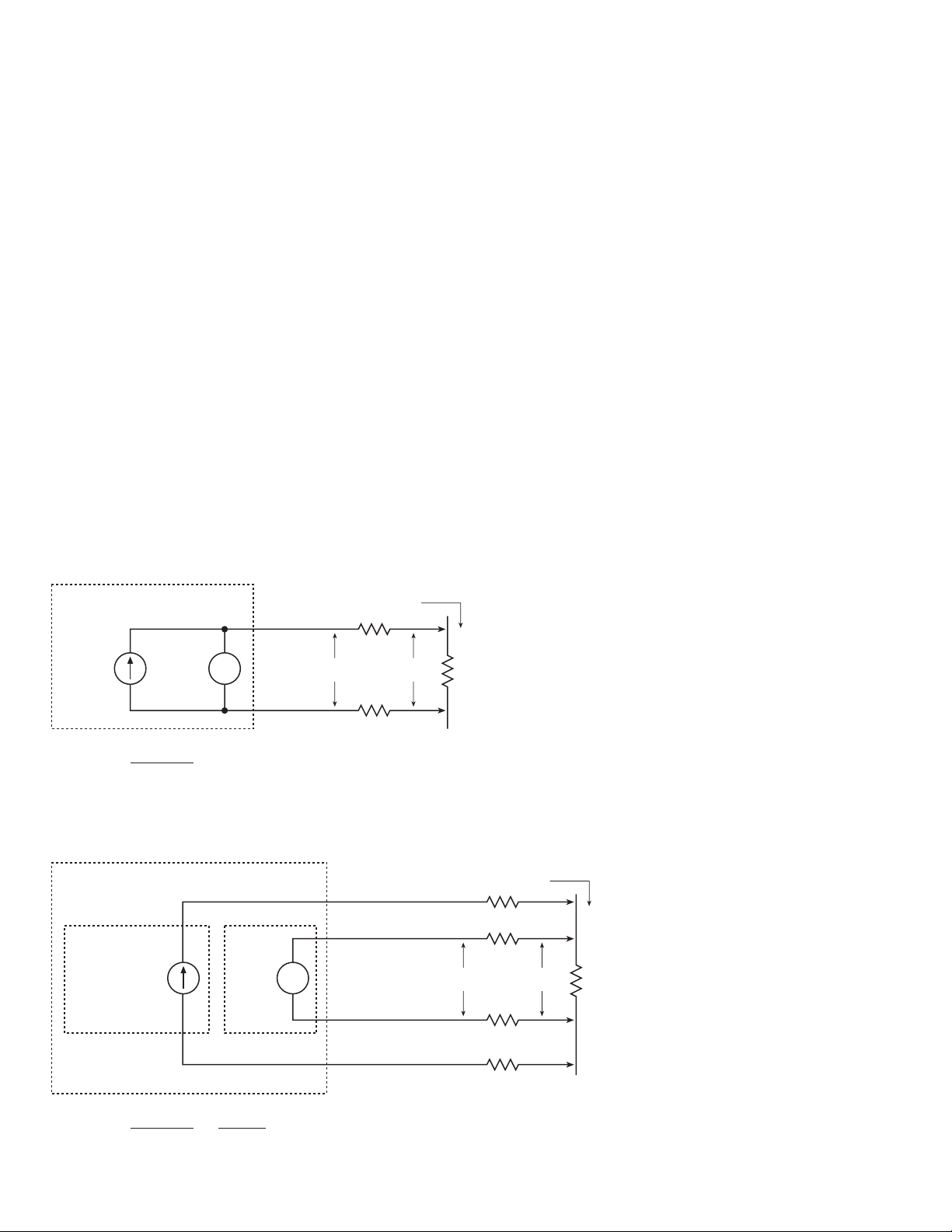
Resistance is usually measured using either two-wire or fourwire methods. A common source of error in low resistance measurements when only two test leads are used is the amount of
series resistance present in the test leads connected to the deviceunder-test (DUT). Figure 7a illustrates the effect of series resistance when the current source and voltmeter use the same pair of
test leads, as for the Contact Verification tests. The main problem
with the two-wire method as applied to low resistance measurements is the lead resistance (R
LEAD
). Since the test current
(I
SOURCE
) causes a small but significant voltage drop across the
lead resistances, the voltage (V
MEAS
) measured by the meter will
not be exactly the same as the voltage (VR) directly across the
test resistance (R
DUT
), and considerable error can result. This is
not a problem for qualitative measurements like the contact verification tests where the object is to distinguish between a “relatively low” resistance and an open circuit. However, this is a
problem for the bridgewire and shunt bar tests, where more precise and accurate measurements are required. To eliminate the
effects of lead resistance, the current source and voltmeter must
be separated and four wires used to connect to the device. Figure
7b shows the four-wire measurement configuration used for the
bridgewire and shunt bar tests. Due to the very high input impedance of the voltmeter, virtually no current flows through the
Sense HI and LO leads and therefore V
MEAS
equals VR. Note
that four-wire ohms measurements are also possible using just
the 2790 DMM, but unlike the 7751 and 7752 modules, the test
current is not programmable.
Noise
In a production environment, measurement performance can be
compromised by external noise produced by machinery, motors,
and even fluorescent lights. This can become a significant problem where low-level measurements are required for a high
impedance DUT connected to the test equipment by long cables.
Normal-mode noise refers to noise signals that appear between
the HI and LO input terminals of an instrument. Careful shielding will reduce normal-mode noise. Using twisted pairs can help
reduce noise generated by magnetic coupling. Using twisted
pairs within an overall shield is an effective method of reducing
normal-mode noise. Power line cycle integration can reduce the
effects of periodic noise signals at power line frequencies (or
harmonics thereof). When the integration time of the A/D converter is set to an integral number of power line cycles, line frequency noise is averaged out over the integration period, resulting in lower normal-mode noise. Nonperiodic noise or noise at
other frequencies is not affected significantly by line cycle integration. In this case, digital filtering that averages multiple measurements can be effective. The Model 2790 offers both line
cycle integration and digital filtering for normal-mode noise
reduction. In general, long integration times and averaging multiple readings can significantly reduce test system throughput. It is
up to the test system designer to make the necessary trade-offs
between test system speed, signal noise, and measurement accuracy. Normally, noise shields should be connected to input LO,
but in some cases where earth-ground based RFI/EMI interference contributes to the noise, connecting to LO may not be completely effective. In this case, using an overall shield tied to
earth-ground may be necessary. Common-mode noise refers to
noise signals that occur between input HI and input LO and
chassis ground. Common-mode noise can be minimized by
connecting all shields and/or grounds to a single point in the
test system.
Page 10
3b. For RS-232 (Serial) Operation:
• PC with available serial port
• Model 7009-5 Shielded RS-232 Cable (wired as
straight-thru cable, not as null modem cable)
4. Custom digital I/O cable for connecting DIO 9-pin male Dsub connector and/or Trigger Link 8-pin female DIN connector of Model 2790 to the component handler
5. Custom wiring harness for connecting the test equipment
to the inflator under test (see “Noise” under “Typical
Sources of Error.”)
Figure 7a. 2-Wire Ohms Measurement Using DMM Ω2 Funcion
Figure 7b. 4-Wire Ohms Measurement Using 7751 I-Source and 2790 DMM
Keithley has determined that one acceptable 2790 system cabling
solution is to use Belden #8899 wire to connect the DUT to the
switch module. This is a very flexible and durable stranded
18AWG wire with rubber insulation rated for 5kV. The wire
bundle should be enclosed in an overall wraparound shield,
such as Zippertubing Series ZTZ-*-SH3. The shield should be
connected to a safety earth ground. Keithley recommends that
users contact The Zippertubing Company for assistance in selecting the appropriate product for their specific applications
(301-527-0488, www.zippertubing.com).
Equipment List
The following equipment is required to assemble the PC controlled air bag inflator test system shown in Figure 1.
1. Model 2790 SourceMeter Switch System
2. One Model 7751 Module
3a. For IEEE-488 (GPIB) Operation:
• PC with Model KPCI-488 GPIB computer interface
board
• Model 7007 Double-Shielded GPIB Cable (available in
different lengths)
Keithley 2790 DMM
R
MEAS
)
R
LEAD
LEAD
Input HI
Fixed
I
SOURCE
V
MEAS
V
V
Input LO
V
MEASURED
R =
I
SOURCE
= R
DUT
+ (2 x R
LEAD
Keithley 2790
SRC HI
SEN HI
7751
Programmable
I
SOURCE
2790
DMM
V
MEAS
V
(DMM Input HI)
SEN LO
(DMM Input LO)
SRC LO
Test Current
(I
V
R
R
V
DUT
MEAS
SOURCE
R
LEAD
R
LEAD
R
LEAD
R
LEAD
)
Test Current
(I
V
R
R
DUT
SOURCE
)
V
MEASURED
R =
I
SOURCE
=
V
I
SOURCE
R
= R
DUT
Page 11

Specifications are subject to change without notice.
All Keithley trademarks and trade names are the property of Keithley Instruments, Inc.
All other trademarks and trade names are the property of their respective companies.
Keithley Instruments, Inc. 28775 Aurora Road • Cleveland, Ohio 44139 • 440-248-0400 • Fax: 440-248-6168
1-888-KEITHLEY (534-8453) • www.keithley.com
© Copyright 2002 Keithley Instruments, Inc. No. 2378
Printed in the U.S.A. 3025KGW
 Loading...