

Page 1

Model 7090 Optical Switch Card
Instruction Manual
A GREATER MEASURE OF CONFIDENCE
Page 2

W ARRANTY
Keithley Instruments, Inc. warrants this product to be free from defects in material and workmanship for a
period of 1 year from date of shipment.
Keithley Instruments, Inc. warrants the following items for 90 days from the date of shipment: probes, cables,
rechargeable batteries, diskettes, and documentation.
During the warranty period, we will, at our option, either repair or replace any product that proves to be defecti ve.
To exercise this warranty, write or call your local Keithley representative, or contact Keithley headquarters in
Cleveland, Ohio. You will be given prompt assistance and return instructions. Send the product, transportation
prepaid, to the indicated service facility . Repairs will be made and the product returned, transportation prepaid.
Repaired or replaced products are warranted for the balance of the original warranty period, or at least 90 days.
LIMIT A TION OF W ARRANTY
This warranty does not apply to defects resulting from product modification without Keithley’s express written
consent, or misuse of any product or part. This warranty also does not apply to fuses, software, non-rechar geable
batteries, damage from battery leakage, or problems arising from normal wear or failure to follow instructions.
THIS WARRANTY IS IN LIEU OF ALL OTHER WARRANTIES, EXPRESSED OR IMPLIED, INCLUDING ANY IMPLIED WARRANTY OF MERCHANTABILITY OR FITNESS FOR A PARTICULAR USE.
THE REMEDIES PROVIDED HEREIN ARE BUYER’S SOLE AND EXCLUSIVE REMEDIES.
NEITHER KEITHLEY INSTRUMENTS, INC. NOR ANY OF ITS EMPLOYEES SHALL BE LIABLE FOR
ANY DIRECT , INDIRECT, SPECIAL, INCIDENTAL OR CONSEQUENTIAL DAMAGES ARISING OUT OF
THE USE OF ITS INSTRUMENTS AND SOFTWARE EVEN IF KEITHLEY INSTRUMENTS, INC., HAS
BEEN ADVISED IN ADVANCE OF THE POSSIBILITY OF SUCH DAMAGES. SUCH EXCLUDED DAMAGES SHALL INCLUDE, BUT ARE NOT LIMITED TO: COSTS OF REMOVAL AND INSTALLATION,
LOSSES SUSTAINED AS THE RESULT OF INJURY T O ANY PERSON, OR DAMAGE T O PROPER TY.
Keithley Instruments, Inc.
Sales Offices: BELGIUM: Bergensesteenweg 709 • B-1600 Sint-Pieters-Leeuw • 02-363 00 40 • Fax: 02/363 00 64
CHINA: Y uan Chen Xin Building, Room 705 • 12 Yumin Road, Dewai, Madian • Beijing 100029 • 8610-6202-2886 • Fax: 8610-6202-2892
FINLAND: Tietäjäntie 2 • 02130 Espoo • Phone: 09-54 75 08 10 • Fax: 09-25 10 51 00
FRANCE: 3, allée des Garays • 91127 Palaiseau Cédex • 01-64 53 20 20 • Fax: 01-60 11 77 26
GERMANY: Landsberger Strasse 65 • 82110 Germering • 089/84 93 07-40 • Fax: 089/84 93 07-34
GREAT BRITAIN: Unit 2 Commerce Park, Brunel Road • Theale • Berkshire RG7 4AB • 0118 929 7500 • F ax: 0118 929 7519
INDIA: Flat 2B, Willocrissa • 14, Rest House Crescent • Bangalore 560 001 • 91-80-509-1320/21 • Fax: 91-80-509-1322
ITALY: Viale San Gimignano, 38 • 20146 Milano • 02-48 39 16 01 • Fax: 02-48 30 22 74
KOREA: FL., URI Building • 2-14 Yangjae-Dong • Seocho-Gu, Seoul 137-130 • 82-2-574-7778 • Fax: 82-2-574-7838
NETHERLANDS: Postbus 559 • 4200 AN Gorinchem • 0183-635333 • Fax: 0183-630821
SWEDEN: c/o Regus Business Centre • Frosundaviks Allé 15, 4tr • 169 70 Solna • 08-509 04 679 • F ax: 08-655 26 10
SWITZERLAND: Kriesbachstrasse 4 • 8600 Dübendorf • 01-821 94 44 • Fax: 01-820 30 81
TAIWAN: 1FL., 85 Po Ai Street • Hsinchu, Taiwan, R.O.C. • 886-3-572-9077• Fax: 886-3-572-9031
28775 Aurora Road • Cleveland, Ohio 44139 • 440-248-0400 • Fax: 440-248-6168
1-888-KEITHLEY (534-8453) • www.keithley.com
© Copyright 2001 Keithley Instruments, Inc.
Printed in the U.S.A.
11/01
Page 3

Model 7090 Optical Switch Card
Instruction Manual
©2001, Keithley Instruments, Inc.
All rights reserved.
Cleveland, Ohio, U.S.A.
Third Printing, December 2001
Document Number: 7090-901-01 Rev. C
Page 4

Manual Print History
The print history shown below lists the printing dates of all Revisions and Addenda created
for this manual. The Revision Le vel letter increases alphabetically as the manual under goes subsequent updates. Addenda, which are released between Revisions, contain important change information that the user should incorporate immediately into the manual. Addenda are numbered
sequentially . When a new Re vision is created, all Addenda associated with the previous Re vision
of the manual are incorporated into the new Revision of the manual. Each ne w Revision includes
a revised copy of this print history page.
Revision A (Document Number 7090-901-01)................................................................. July 2001
Revision B (Document Number 7090-901-01)........................................................... October 2001
Revision C (Document Number 7090-901-01)....................................................... December 2001
All Keithley product names are trademarks or registered trademarks of Keithley Instruments, Inc.
Other brand names are trademarks or registered trademarks of their respective holders.
Page 5

S
afety Precautions
The following safety precautions should be observed before using this product and any associated instrumentation. Although
some instruments and accessories would normally be used with non-hazardous voltages, there are situations where hazardous
conditions may be present.
This product is intended for use by qualified personnel who recognize shock hazards and are familiar with the safety precautions
required to avoid possible injury. Read and follow all installation, operation, and maintenance information carefully before using the product. Refer to the manual for complete product specifications.
If the product is used in a manner not specified, the protection provided by the product may be impaired.
The types of product users are:
Responsible body
ment is operated within its specifications and operating limits, and for ensuring that operators are adequately trained.
Operators
instrument. They must be protected from electric shock and contact with hazardous live circuits.
Maintenance personnel
voltage or replacing consumable materials. Maintenance procedures are described in the manual. The procedures explicitly state
if the operator may perform them. Otherwise, they should be performed only by service personnel.
Service personnel
trained service personnel may perform installation and service procedures.
Keithley products are designed for use with electrical signals that are rated Installation Category I and Installation Category II,
as described in the International Electrotechnical Commission (IEC) Standard IEC 60664. Most measurement, control, and data
I/O signals are Installation Category I and must not be directly connected to mains voltage or to voltage sources with high transient over-voltages. Installation Cate gory II connections require protection for high transient over -voltages often associated with
local A C mains connections. Assume all measurement, control, and data I/O connections are for connection to Category I sources unless otherwise marked or described in the Manual.
Exercise extreme caution when a shock hazard is present. Lethal voltage may be present on cable connector jacks or test fixtures.
The American National Standards Institute (ANSI) states that a shock hazard exists when v oltage le vels greater than 30V RMS,
42.4V peak, or 60VDC are present.
circuit before measuring.
Operators of this product must be protected from electric shock at all times. The responsible body must ensure that operators
are prevented access and/or insulated from every connection point. In some cases, connections must be exposed to potential
human contact. Product operators in these circumstances must be trained to protect themselves from the risk of electric shock.
If the circuit is capable of operating at or above 1000 volts,
Do not connect switching cards directly to unlimited power circuits. They are intended to be used with impedance limited sources. NEVER connect switching cards directly to AC mains. When connecting sources to switching cards, install protective devices to limit fault current and voltage to the card.
Before operating an instrument, make sure the line cord is connected to a properly grounded power receptacle. Inspect the connecting cables, test leads, and jumpers for possible wear, cracks, or breaks before each use.
When installing equipment where access to the main power cord is restricted, such as rack mounting, a separate main input power disconnect device must be provided, in close proximity to the equipment and within easy reach of the operator.
For maximum safety, do not touch the product, test cables, or any other instruments while power is applied to the circuit under
test. ALWAYS remove power from the entire test system and discharge any capacitors before: connecting or disconnecting cables or jumpers, installing or removing switching cards, or making internal changes, such as installing or removing jumpers.
is the individual or group responsible for the use and maintenance of equipment, for ensuring that the equip-
use the product for its intended function. They must be trained in electrical safety procedures and proper use of the
perform routine procedures on the product to keep it operating properly, for example, setting the line
are trained to work on live circuits, and perform safe installations and repairs of products. Only properly
A good safety practice is to expect that hazardous voltage is present in any unknown
no conductive part of the circuit may be exposed.
Page 6

Do not touch any object that could provide a current path to the common side of the circuit under test or power line (earth) ground. Always make measurements with dry hands while standing on a dry , insulated surface capable of withstanding the voltage being measured.
The instrument and accessories must be used in accordance with its specifications and operating instructions or the safety of the
equipment may be impaired.
Do not exceed the maximum signal levels of the instruments and accessories, as defined in the specifications and operating information, and as shown on the instrument or test fixture panels, or switching card.
When fuses are used in a product, replace with same type and rating for continued protection against fire hazard.
Chassis connections must only be used as shield connections for measuring circuits, NOT as safety earth ground connections.
If you are using a test fixture, keep the lid closed while power is applied to the device under test. Safe operation requires the use
of a lid interlock.
If a screw is present, connect it to safety earth ground using the wire recommended in the user documentation.
!
The symbol on an instrument indicates that the user should refer to the operating instructions located in the manual.
The symbol on an instrument shows that it can source or measure 1000 volts or more, including the combined effect of
normal and common mode voltages. Use standard safety precautions to avoid personal contact with these voltages.
The
WARNING
information very carefully before performing the indicated procedure.
CAUTION
The
ranty.
Instrumentation and accessories shall not be connected to humans.
Before performing any maintenance, disconnect the line cord and all test cables.
T o maintain protection from electric shock and fire, replacement components in mains circuits, including the power transformer ,
test leads, and input jacks, must be purchased from Keithley Instruments. Standard fuses, with applicable national safety approvals, may be used if the rating and type are the same. Other components that are not safety related may be purchased from
other suppliers as long as they are equivalent to the original component. (Note that selected parts should be purchased only
through Keithley Instruments to maintain accuracy and functionality of the product.) If you are unsure about the applicability
of a replacement component, call a Keithley Instruments office for information.
To clean an instrument, use a damp cloth or mild, water based cleaner. Clean the exterior of the instrument only. Do not apply
cleaner directly to the instrument or allow liquids to enter or spill on the instrument. Products that consist of a circuit board with
no case or chassis (e.g., data acquisition board for installation into a computer) should never require cleaning if handled according to instructions. If the board becomes contaminated and operation is affected, the board should be returned to the factory for
proper cleaning/servicing.
heading in a manual explains dangers that might result in personal injury or death. Al ways read the associated
heading in a manual explains hazards that could damage the instrument. Such damage may inv alidate the war -
11/01
Page 7

Model 7090 1xN Series Optical Switch Card Specifications
General Specifications:
Switching Time
(1)
Reset/Open
Settle/Close
Maximum Switch
Drive Current:
Dimensions Width
Length
Height
Weight 0.66kg
Temperature Operating
Storage
Relative Humidity Up to 35 oC <80% RH Non-Condensing
EMC European Union Directive 89/336/EEC EN61326
Safety European Union Directive 73/23/EEC EN61010-1
1x4 1x8 1x16
250ms 315ms 450ms
450ms 500ms 630ms
300mA 300mA 300mA
114 mm [4.5 in]
272 mm [10.75 in]
32 mm [1.25 in ]
0 to 40 oC
-20 to 65
(2)
o
C
Referenced Switch Manufacturer Optical Specifications7:
Typ. Max. Units
Wavelength Range 780 to 1650 nm
Switch Life > 10 million cycles (min.)
Insertion Loss
Repeatability
Back Reflection (SM/MM)
Polarization Dependent Loss (PDL)
Crosstalk - -80 dB
3
5
4
6
0.6 1.2 dB
- +/-0.03 dB
-60 / -20 -55 / - dB
- 0.05 dB
NOTES:
1. Actuation time measured from system trigger. Reset/Open refers to Channel N to Reset time. Settle/Close refers to Reset to Channel N or
Channel N to Channel M time. Reset position is optically blocked.
1. At higher operating temperatures, a typical 0.1 dB and 0.3dB additive insertion loss for each channel should be expected for the strain relief
and bulkhead models respectively.
1. Measured at 23 ± 5 °C.
1. Based on standard 1m pigtail length.
1. Sequential repeatability for 100 cycles at constant temperature after warm up. (Difference in Insertion Loss).
1. Measured at 1550 nm.
1. All optical specifications are referenced without connectors and are guaranteed by switch manufacturer only. Connectorization data will be
provided for Insertion Loss and Back Reflection for each channel per switch card.
Specifications are subject to change without notice.
HW 12/06/01
Rev. C
Page 8

Model 7090 Switch Properites
Configuration Single Channel, 1xN non-blocking switch
Model Number
7090-4-1 1x4 Single-Mode fiber (SMF-28) 9/125 each ch. 1290-1650 FC/APC 1 meter
7090-4-2BH
Channels
(8)
1x4 Single-Mode fiber (SMF-28) 9/125 each ch. 1290-1650 FC/SPC Bulkhead Connector
7090-8-3 1x8 Single-Mode fiber (SMF-28) 9/125 each ch. 1290-1650 FC/APC 1 meter
7090-8-4 1x8 Multi-Mode fiber (MMF) 62.5/125 each ch. 780-1350 FC/SPC 1 meter
7090-8-5 1x8 Single Mode fiber (SMF-28) 9/125 each ch. 1290-1650 FC/SPC 1 meter
7090-16-6 1x16 Single Mode fiber (SMF-28) 9/125 each ch. 1290-1650 FC/SPC 1 meter
7090-16-7 1x16 Single Mode fiber (SMF-28) 9/125 each ch. 1290-1650 FC/APC 1 meter
NOTE:
1. This model contains a back plate with 5 FC/PC mating sleeve adapters. The fiber length is not applicable compared with the other models
that are fiber pigtailed. Additional insertion loss due to the mating sleeve adapter is not accounted for in the referenced switch specification.
# of
Fiber
Type
Wavelength
(nm) Connector FiberLength
HW 12/06/01
Rev. C
Page 9

T able of Contents
1 General Information
Introduction ................................................................................ 1-2
Feature overview ........................................................................ 1-2
Warranty information ................................................................. 1-2
Manual addenda ......................................................................... 1-2
Safety symbols and terms .......................................................... 1-3
Specifications ............................................................................. 1-3
Unpacking and inspection .......................................................... 1-3
Inspection for damage ......................................................... 1-3
Handling precautions .......................................................... 1-3
Shipment contents ............................................................... 1-4
Instruction manual .............................................................. 1-4
Repacking for shipment ...................................................... 1-4
Switch properties ........................................................................ 1-4
2 Installation and Connections
Introduction ................................................................................ 2-2
Handling and cleaning precautions ............................................ 2-2
Handling fiber-optic cables ................................................. 2-2
Storing optical connectors ................................................... 2-3
Cleaning optical connectors ................................................ 2-3
Card configuration ...................................................................... 2-4
Card layouts ........................................................................ 2-4
Switching conventions ........................................................ 2-6
Switching diagram .............................................................. 2-7
Card installation and removal .................................................... 2-8
Card installation .................................................................. 2-8
Card removal ....................................................................... 2-9
Card connections ...................................................................... 2-10
Mating optical connectors ................................................. 2-10
Bulkhead version connectors ............................................ 2-10
3 Operation
Introduction ................................................................................ 3-2
Optical signal characteristics........................................................3-2
Operation overview .................................................................... 3-2
Card programming ..................................................................... 3-3
Front panel card programming ............................................ 3-4
Remote card programming ................................................. 3-6
Error conditions .......................................................................... 3-8
Page 10

4 Service Information
Introduction ................................................................................ 4-2
Handling and cleaning precautions ............................................ 4-2
Handling fiber-optic cables ................................................. 4-2
Storing optical connectors ................................................... 4-3
Cleaning optical connectors ................................................ 4-3
Performance verification ............................................................. 4-3
Environmental conditions .................................................... 4-3
Insertion loss tests (an example) ......................................... 4-4
Principles of operation ................................................................ 4-7
Block diagram ..................................................................... 4-7
Power supplies ..................................................................... 4-7
Page 11

List of Illustrations
2 Installation and Connections
Figure 2-1 Card configuration for versions with attached fiber cables .... 2-4
Figure 2-2 Typical card configuration for bulkhead versions................... 2-5
Figure 2-3 Functional diagram ................................................................ 2-7
Figure 2-4 Card installation ..................................................................... 2-9
4 Service Information
Figure 4-1 Optical insertion loss test connection block diagram ............ 4-5
Figure 4-2 Block diagram ........................................................................ 4-7
Page 12

Page 13

List of T ables
3 Operation
Table 3-1 Error conditions ..................................................................... 3-8
Page 14

Page 15

1
General Information
Page 16

1-2 General Information Model 7090 Instruction Manual
Introduction
This section contains general information about the Model 7090 Optical Switch Card. The
information is organized as follows:
• Feature overview
• Warranty information
• Manual addenda
• Safety symbols and terms
• Specifications
• Unpacking and inspection
• Switch properties
If you have any questions after reviewing this information, please contact your local
Keithley representativ e or call one of our Applications Engineers at 1-800-348-3735 (U.S.
and Canada only). Worldwide phone numbers are listed at the front of this manual.
Feature overview
The Model 7090 optical switch cards have the following features (depending on model):
•1 × N multiplexer optical switching
• 780 to 1650nm wavelength
• SMF-28 or MMF fiber type
W arranty information
Warranty information is located at the front of this instruction manual. Should your
Model 7090 require warranty service, contact the Keithley representative or authorized
repair facility in your area for further information. When returning the card for repair, be
sure to fill out and include the service form at the back of this manual to provide the repair
facility with the necessary information.
Manual addenda
Any improvements or changes concerning the switch card or manual will be explained in
an addendum included with the manual. Be sure to note these changes and incorporate
them into the manual.
Page 17

Model 7090 Instruction Manual General Information 1-3
Safety symbols and terms
The following symbols and terms may be found on the multiplexer card or used in this
manual.
The symbol indicates that the user should refer to the operating instructions located in
!
the manual.
The
symbol
safety precautions to avoid personal contact with these voltages.
The
WARNING
personal injury or death. Always read the associated information very carefully before
performing the indicated procedure.
The
CAUTION
multiplexer card. Such damage may invalidate the warranty.
shows that high voltage may be present on the terminal(s). Use standard
heading used in this manual explains dangers that might result in
heading used in this manual explains hazards that could damage the
Specifications
Full Model 7090 specifications are included at the front of this manual.
Unpacking and inspection
Inspection for damage
The Model 7090 is packaged in a re-sealable, anti-static bag to protect it from damage due
to static discharge and from contamination that could degrade its performance. Before
removing the card from the bag, observe the precautions on handling discussed below.
Handling precautions
• Always grasp the card by the covers. Do not touch board surfaces or components.
• After removing the card from its anti-static bag, inspect it for any obvious signs of
physical damage. Report any such damage to the shipping agent immediately.
• When the card is not installed and connected, keep the card in its anti-static bag,
and store it in the original packing carton.
• Care should be taken when handling fiber-optic cables. They can be easily damaged by excessive handling and improper use.
Page 18

1-4 General Information Model 7090 Instruction Manual
Shipment contents
The following items are included with every Model 7090 order:
• Model 7090 Optical Switch Card
• Model 7090 Instruction Manual
• Additional accessories as ordered
Instruction manual
If an additional Model 7090 Instruction Manual is required, order the manual package,
Keithley part number 7090-901-00. The manual package includes an instruction manual
and any pertinent addenda.
Repacking for shipment
Should it become necessary to return the Model 7090 for repair, carefully pack the unit in
its original packing carton or the equivalent, and perform the following:
• Call the Repair Department at 1-800-552-1115 for a Return Material Authorization
(RMA) number.
• Advise as to the warranty status of the card.
• Write ATTENTION REPAIR DEPARTMENT and the RMA number on the shipping label.
• Fill out and include the service form located at the back of this manual.
Switch properties
The switch properties for the various Model 7090 card configurations are summarized in
the specifications and switch properties guide supplied with each card.
Page 19

2
Installation and Connections
Page 20

2-2 Installation and Connections Model 7090 Instruction Manual
Introduction
This section contains information about overall card configuration and connections, and it
is organized as follows:
• Handling and cleaning precautions
• Card configuration
• Card installation and removal
• Card connections
WARNING
It is the responsibility of the customer to operate instruments in a safe
manner. Follow all applicable safety regulations for installing, configuring, and using the Model 7090. The Model 7090, as installed, should
be approved by the appropriate safety personnel, such as the responsible Laser Safety Officer or equivalent.
Suggested starting points for workplace regulations and standards:
ANSIZ136,1, IEC 825, OSHA 29 CFR 1910.
As a general rule, always be aware of workplace hazards, strive to minimize
them, and work safely.
Handling and cleaning precautions
Handling fiber-optic cables
Treat fiber optic cables with care to avoid cable damage and minimize optical loss. The
minimum bend radius for most optical cables is 35mm. Never bend an optical cable more
sharply than this specification. Optical performance will degrade, and the cable may
break.
General handling precautions include:
• Avoid bending the optical cable near a cable strain relief boot or switch housing.
Bending an optical cable near a strain relief boot or switch housing is one of the
easiest ways to permanently damage the optical fiber.
• Avoid bending the optical cable over a sharp edge.
• Av oid using cable tie wraps to hold optical cable. T ie wraps can create micro-bends
or break an optical cable when tightened. Micro-bends can cause a dramatic reduction in optical performance.
Page 21

Model 7090 Instruction Manual Installation and Connections 2-3
• Do not pull on the bare fiber. Doing so can break the fiber inside the component.
• Av oid using soldering irons near optical cable. Accidental damage can easily occur
when a soldering iron is used near an optical cable. In addition, solder splatter can
contaminate and permanently damage optical fiber connectors.
• In order to obtain the most stable, repeatable optical performance, immobilize optical cables using wide pieces of tape or some form of mechanical cushion after the
optical cables have been connected.
Storing optical connectors
All switch cards are shipped with dust caps in place covering all optical connectors. Optical connectors should remain covered at all times when the card is not in use.
Cleaning optical connectors
Clean any exposed connector using a cleaning kit supplied by the connector manufacturer
or high-grade isopropyl alcohol and a cotton swab. To clean with alcohol and a swab, dab
the tip of a cotton swab in alcohol and then shake off any e xcess alcohol. The tip should be
moist,
not dripping
around the connector ferrule. Either allow the connector a minute to dry, or blow-dry the
connector using clean compressed air. Be careful when using compressed air because
improper use may deposit a spray residue.
wet. Stroke the swab tip gently across the surface of the connector and
Page 22

2-4 Installation and Connections Model 7090 Instruction Manual
Card configuration
Card layouts
Figure 2-1 shows the general layout of Model 7090 versions with attached fiber cables.
The card includes one common optical fiber cable and a number of channels (depending
on model). Figure 2-2 shows the typical layout of bulkhead versions.
Figure 2-1
Card configuration for versions with attached fiber cables
M200
C15
C1
C8
C9
R4
C10
R14 R13
U3
C14
U5
R19
C2
U2
P2001
R16
R17
R15
R18
R2
Y1
C3
R3
C7
C6
R1
U1
C13
C12
U4
C11
C4
SQ4
R9
R10
R11
R12
OPTICAL
SWITCH
CHANNEL
+
SIZE
R5
R6
1x4
1x8
C5
R7
R8
M202
DS1 ERROR
M201
*BAR CODE*
J1
M01
Fiberoptic Switch
U. S. Patent # 4,896,935
Made in U.S.A.
Fiber-optic
Connectors
(Number depends
on Model)
Mainframe
Mating Connector
Page 23
Model 7090 Instruction Manual Installation and Connections 2-5
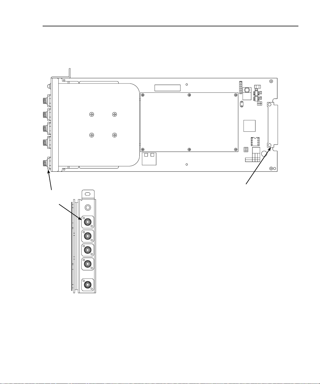
Figure 2-2
Typical card configuration for bulkhead versions
TOP VIEW
Fiberoptic Switch
Mainframe
Bulkhead
connectors
ERROR
mating connector
4
321
CONNECTOR
EDGE VIEW
COM
Page 24

2-6 Installation and Connections Model 7090 Instruction Manual
Switching conventions
Electrical industries
Given channel
Channel “Close”
⇒ Channel path electrically connected ⇒ current flow.
Channel “Open”
⇒ Channel path not electrically connected ⇒ no current flow.
COM
COM
COM
CHannel N
CHannel N
CHannel N
Optical industries
Given channel
Channel “Close”
⇒ Channel path obstructed ⇒ no light can pass.
Channel “Open”
⇒ Channel path un-obstructed ⇒ light can pass.
NOTE
COM
COM
We are applying electrical conventions with optical signals.
CHannel N
CHannel N
CHannel N
Optical signals
“Close” ⇒ Light can pass
“Open” ⇒ Light cannot pass
⇒
May not be obvious to optical field personnel.
Page 25

Model 7090 Instruction Manual Installation and Connections 2-7
Switching diagram
Figure 2-3 shows a switching diagram of the Model 7090. The card is arranged as one
1
× Ν
optical multiplexer. The unit is basically an opto-mechanical switch that selects
individual fiber channels using a high-resolution stepper motor , which mo v es the common
moving fiber into direct alignment with one of the fixed fibers. Optical switching is passiv e
and bi-directional. When the switch is reset, the moving fiber is in the optically off position.
Figure 2-3
Functional diagram
Optically Off
(Reset) Position
Channel 1
Channel 2
Channel 3
Channel 4
Common
Moving
Fiber
Moving
Armature
Channel 5
Channel 6
Channel 7
Channel 8
Note: Number of Channels
depends on Model.
Page 26

2-8 Installation and Connections Model 7090 Instruction Manual
Card installation and removal
This paragraph explains how to install and remove the Model 7090 card assembly from
the Model 7001 mainframe. (Model 7002 installation is similar.)
WARNING
NOTE
To prevent performance degradation caused by contamination, handle the card
only by the edges and covers.
Card installation
Refer to Figure 2-4 to install the card assembly in the Model 7001 mainframe.
WARNING
1. Open the ejector arms at the back edge of the card.
2. Slide the card edges into the guide rails inside the mainframe.
3. Carefully push the card all the way forward until the ejector arms engage the
mounting cups.
4. Push in on the card edge and ejector arms until the card is properly seated.
5. Make sure the ejector arms are properly latched.
NOTE
Before using Model 7090, it would be a good idea to clean connectors and keep
dust caps in place until the unit is ready to interface to an optical system.
It is the responsibility of the customer to operate instruments in a safe
manner. Follow all applicable safety regulations for installing, configuring, and using the Model 7090. The Model 7090, as installed, should
be approved by the appropriate safety personnel, such as the responsible Laser Safety Officer or equivalent.
Turn off the power, and disconnect all line cords before installing the
optical switch card.
Page 27

Model 7090 Instruction Manual Installation and Connections 2-9
Figure 2-4
Card installation
Ejector Cup
Ejector Arms (2)
Card removal
Follow the steps below to remove the optical switch card from the mainframe:
WARNING
1. Pull out on the ejector arms until the card pulls free from the internal connector.
2. Carefully slide the card out of the switching mainframe.
Turn off and disconnect any laser sources and disconnect the line cord
before removing the card.
Page 28

2-10 Installation and Connections Model 7090 Instruction Manual
Card connections
Mating optical connectors
After installing the card, make your optical connections as needed. Observe the following
precautions when mating optical connectors:
• Clean both connectors prior to mating. Any small particles trapped during the mating process can permanently damage the connector.
• Insert the appropriate connector ferrule smoothly into the adapter. Do not allo w the
fiber tip to contact any surface. If the tip accidentally contacts a surface before mat-
ing, do not make the connection. Re-clean the connector, and try again.
• Tighten the connector until it is finger tight, or to the torque specified by the connector manufacturer. Do not over-tighten the connector as doing so can lead to
optical loss and connector damage.
• Check the optical insertion loss. If the loss is unacceptable, remove the connector,
re-clean both ends of the mate, and reconnect. You may have to repeat this process
several times before a low-loss connection is made.
• After you make the connection, monitor the stability of the optical throughput for a
few minutes. Optical power trending (slo wly increasing or decreasing) is caused by
the slow evaporation of alcohol trapped in the connection. Continue to monitor
optical power until it stabilizes. (Optical power trending can also be a natural ef fect
of the laser source as it warms up.) If the loss is unacceptable, re-clean the connectors, and start again.
Bulkhead version connectors
The bulkhead versions hav e the fiber coming from the optical switch module connected to
a bulkhead on the rear of the card. This bulkhead contains FC/PC mating sleeves for user
connections. The error light is also mounted in the bulkhead. Bulkhead connections to this
card can be made in the same manner as described in
Also refer to
age.
Handling and cleaning precautions
Mating optical connectors
at the front of this section to avoid dam-
above.
Page 29

3
Operation
Page 30

3-2 Operation Model 7090 Instruction Manual
Introduction
WARNING
This section contains information about operating considerations for the Model 7090
Optical Switch Card. The information is organized as follows:
• Optical signal characteristics
• Operation overview
• Card programming
• Error conditions
It is the responsibility of the customer to operate instruments in a safe
manner. Follow all applicable safety regulations for installing, configuring, and using the Model 7090. The Model 7090, as installed, should
be approved by the appropriate safety personnel, such as the responsible Laser Safety Officer or equivalent.
Suggested starting points for workplace regulations and standards:
ANSIZ136,1, IEC 825, OSHA 29 CFR 1910.
As a general rule, always be aware of workplace hazards, strive to minimize them, and work safely.
Optical signal characteristics
Refer to the specifications and switch properties guide supplied with this card for card signal characteristics.
Operation overview
The Model 7090 Optical Switch Card contains a fiber-optic 1× N switch module along
with the appropriate electronics to interface to the Model 7001/7002 Switch Systems. The
fiber-optic switch contains a number of channels (depending on model), one switched
common channel, and one reset position. During normal operation, the switch will
optically connect the common channel to one of the available channels, or to the reset
position, which is optically blocked. When an optical channel is connected, the switch will
Page 31

Model 7090 Instruction Manual Operation 3-3
transmit light through the common and connected channel passing wavelengths 780nm to
1650nm with associated losses according to system setup and switch specifications.The
actual switch optical characteristics and system losses vary depending on the particular
switch parameters ordered and the characteristics of the system in use (refer to the switch
properties guide).
Upon system power-up, the optical switch goes through an initialization period of
approximately one second. The Model 7001/7002 system will be ready to receive
instructions after approximately six seconds at which time the switch will be in reset
position. Once a switching command is complete, the optical switch module requires up to
0.5 seconds to execute, model specific. Max in now .63 (depending on model). While the
optical switch is busy changing switch channels, the optical channel connections are
invalid. The optical switch is a relatively slow device due to the mechanical nature of its
switching design.
Card programming
The optical switch can be in reset or have only one optical channel connected at any time.
Once the Model 7001/7002 is programmed, and the optical switch is auto-initialized, the
switch will be ready to receive switching instructions via the front panel of the Model
7001/7002, or with the appropriate SCPI commands. When closing individual channels,
the channel list should be cleared between single channel CLOSE commands to avoid the
logical impossibility of closing more than one channel at a given time. In other words, a
CLOSE command is executed properly when the intention is to close only one channel,
and only one channel should be included in the channel list at a time. The preferred
method of switching is to program a scan. Refer to 7001 Operating Manual for programming details.
NOTE
Operation in single channel mode will r esult in switch reset operations between
each channel CLOSE operation.
Page 32

3-4 Operation Model 7090 Instruction Manual
Front panel card programming
Selecting the single-channel mode
1. Upon initial power-up of the Model 7001, wait until the menu system becomes
active.
2. Press the SCAN CONFIGURATION key.
3. Press the key three times to select “CHAN-RESTRICTIONS.”
4. Press ENTER, select “SINGLE-CHAN,” then press ENTER again.
5. Press the key once, select “ON,” and press ENTER. (Auto-reset is performed at
this time.)
6. Press the EXIT key twice to return to the channel status display.
The message “SELECT CHANNELS” is displayed, and the current state of all channels is
shown. At this point, you can enter a single desired channel that is to be opened or closed
via the numeric keypad.
Closing a single optical channel
1. Select desired channel to close (1-N). For example, to close channel 3 on a card
installed in slot 1, key in 1!3 via the numeric keypad.
2. Press the CLOSE key.
After the appropriate close time elapses, the selected channel will be closed, and a valid
optical connection will be maintained.
NOTE Be sure to close only one channel at a time.
Opening an optical channel
1. Select the desired channel to open (1-N). For example, to open slot 1, channel 3,
key in 1!3 via the numeric keypad.
2. Press the OPEN key.
3. Because of the single-channel nature of the switch module, opening a given
channel results in an optically blocked connection, which is identical to the reset
position.
Resetting the optical switch
T o reset the optical switch at an y time, simply press the OPEN ALL key. Recycling power
will result in a reset condition as well.
Page 33

Model 7090 Instruction Manual Operation 3-5
Manually scanning channels
Program ARM, SCAN, and CHANNEL layers appropriately.
1. Press the SCAN LIST key.
2. Enter all desired channels in the scan list, for example: 1!1, 1!2, 1!4, 1!7.
3. Repeatedly press the STEP key to cycle through the scan list, closing one channel
at a time starting at the beginning of the list.
Scanning is the preferred method of switching the Model 7090.
NOTE Refer to 7001 Manual to configure ARM layer, SCAN layer, CHANNEL layer
and their respective spacings.
Automatically scanning channels
Program ARM and SCAN layers appropriately.
1. Press the SCAN LIST key.
2. Enter all desired channels in the scan list, for example: 1!1, 1!2, 1!4.
3. Press the SCAN button.
4. Select “CHAN-CONTROL,” then press the ENTER key.
5. Select “CHANNEL-SPACING,” then press ENTER.
6. For timed auto-switching, select “TIMER,” then press ENTER.
7. Enter the appropriate time in seconds between switch closures (for example,
0001.000) using the keypad.
8. Press ENTER to complete timer programming.
9. Press the EXIT key three times to return to the scan list display.
10. Press STEP once to arm and execute the auto scan.
11. Press OPEN ALL to stop scanning the scan list.
Page 34

3-6 Operation Model 7090 Instruction Manual
Remote card programming
Selecting the single-channel mode
Use the following SCPI command to enable the single-channel mode:
:CONF:SCH ON
Closing a single optical channel
Send the following SCPI command to close the desired channel:
:CLOS <channel>
For example, the following command will close channel 2 of a Model 7090 installed in
slot 1:
:CLOS (@ 1!2)
Again, be sure not to close more than one channel at a time.
Opening an optical channel
Use the following command to open the closed channel:
:OPEN <channel>
For example, the command below will open previously closed slot 1, channel 2:
:OPEN (@ 1!2)
Resetting the optical switch
Send the :OPEN ALL command to reset the optical switch.
Page 35

Model 7090 Instruction Manual Operation 3-7
Scanning channels
There are a number of commands associated with scanning (see the Model 7001 or 7002
Instruction Manual). However, you can perform a simple scan using only the following
five commands:
*RST
:CONF:SCH ON
:TRIG:SEQ:COUN:AUT ON
:ROUT:SCAN <list>
:INIT
The *RST command selects the default scan configuration, while the second command
enables the single-channel mode. The third command automatically sets the channel count
to the number of channels in the scan list. The :ROUT:SCAN command programs the scan
list, and the :INIT command takes the mainframe out of the idle state and performs the
scan.
For example, send the following commands to scan through four channels of a card
installed in slot 1:
*RST
:CONF:SCH ON
:TRIG:SEQ:COUN:AUT ON
:ROUT:SCAN (@ 1!1:1!4)
:INIT
Multiple 7090 cards
Multiple 7090 cards can be programmed in the usual way. Single channel mode option
must be off if multiple cards are to have channel closures at the same time.
Page 36

3-8 Operation Model 7090 Instruction Manual
Error conditions
Refer to the Model 7001 or Model 7002 User Manual for details of Model 7001/7002
front panel reported errors.
For some errors contingent on user actions, the Model 7090 provides one red LED located
at the back of the card to indicate certain error conditions, which are summarized in
Table 3-1.
Table 3-1
Error conditions
LED Status Cause Resolution
On continuously The switch module has an internal
hardware malfunction.
7090 must be returned to the factory to be
serviced.
Blinks at ~ 2Hz rate User error. The 7090 received a
close operation to close more than
one channel.Under these circumstances, it is not clear which single
channel should have been closed.
For laser safety reasons, the 7090
resets to avoid a potential open
beam condition.
NOTE 7001/2 front panel will
still show conflicting
channels as closed.
Most likely, the 7001/2 system was not programmed for single channel mode when it
should have been. Or, there is an error in the
scan list or channel list. Refer to 7001 Manual
for card programming details. This error
clears after the next valid command is given
such as an OPEN ALL for reset.
Page 37

4
Service Information
Page 38

4-2 Service Information Model 7090 Instruction Manual
Introduction
This section contains service information for the Model 7090. The information is organized as follows:
• Handling and cleaning precautions
• Performance verification
• Principles of operation
WARNING The information in this section is intended only for qualified service
personnel. Some of the procedures may expose you to hazardous conditions that could result in personal injury or death. Do not perform
these procedures unless you are qualified to do so.
Handling and cleaning precautions
Handling fiber-optic cables
Treat cables with care to avoid cable damage and minimize optical loss. The minimum
bend radius for most optical cables is 35mm. Never bend an optical cable more sharply
than this specification. Optical performance will degrade, and the cable may break.
General handling precautions include:
• Avoid bending the optical cable near a cable strain relief boot or switch housing.
Bending an optical cable near a strain relief boot or switch housing is one of the
easiest ways to permanently damage the optical fiber.
• Avoid bending the optical cable over a sharp edge.
• Av oid using cable tie wraps to hold optical cable. T ie wraps can create micro-bends
or break an optical cable when tightened. Micro-bends can cause a dramatic reduction in optical performance.
• Do not pull on the bare fiber. Doing so can break the fiber inside the component.
• Av oid using soldering irons near optical cable. Accidental damage can easily occur
when a soldering iron is used near an optical cable. In addition, solder splatter can
contaminate and permanently damage optical fiber connectors.
• In order to obtain the most stable, repeatable optical performance, immobilize optical cables using wide pieces of tape or some form of mechanical cushion after the
optical cables have been connected.
Page 39

Model 7090 Instruction Manual Service Information 4-3
Storing optical connectors
All switches are shipped with dust caps in place covering all optical connectors. Optical
connectors should remain covered at all times when the instrument is not in use.
Cleaning optical connectors
Clean any exposed connector using a cleaning kit supplied by the connector manufacturer
or high-grade isopropyl alcohol and a cotton swab. To clean with alcohol and a swab, dab
the tip of a cotton swab in alcohol and then shake off any e xcess alcohol. The tip should be
moist, not dripping wet. Stroke the swab tip gently across the surface of the connector and
around the connector ferrule. Either allow the connector a minute to dry, or blow-dry the
connector using compressed air. Be careful when using compressed air because improper
use may deposit a spray residue. Connectors should always be properly cleaned before
each use.
Performance verification
The following paragraphs discuss performance verification procedures for the
Model 7090. The procedures involve recommended equipment, test setup, and the procedure for measuring insertion loss.
Environmental conditions
All verification measurements should be made at an ambient temperature between 18° and
28°C, and at a relative humidity of less than 70%. Refer to Model 7090 specifications for
environmental operating ranges.
Page 40

4-4 Service Information Model 7090 Instruction Manual
Insertion loss tests (an example)
Two specifications are given for insertion loss. The first specification is a maximum and
typical insertion loss reflecting the quality of switch modules manufactured without connectors. The second specification is an actual insertion loss measurement provided with
each switch module that was measured with the specific connectors in the measurement.
T o v erify module quality, fiber connections and connector connections, insertion loss measurements should be compared to the second insertion loss specification and might fall
within range of the first insertion loss specification. Insertion loss measurements should be
done with the same wavelength(s) as those provided with the Model 7090. The following
is an example only, and in many cases, the required equipment will vary.
Insertion loss setup
The system shown in Figure 4-1 is sufficient to measure and calculate insertion loss on a
given channel of the Model 7090. Two optical patch cords are required to interface the
source and detection equipment. Since these connectors may vary, other patch cords may
be required. The example system contains APC connectors. Patch Cord 1 is part of the
laser source system, and Patch Cord 2 is part of the detector system. Connectors should be
properly cleaned prior to any optical measurements.
Calculating insertion loss
The laser light source is to be injected into the common channel of the Model 7090 card.
When channel N is closed, the detection system is used to measure the optical power output of the DUT. This test is a relative test, and patch cord losses need not be specifically
known. Two parameters are required to calculate insertion loss. The first is the optical
power of the laser system going into the common channel of the Model 7090 (PIN), and
the second is the optical power of the detector system coming from the connected channel
N of the Model 7090 (P
passive optics between them is, by definition, insertion loss:
Insertion Loss (dB) = -10LOG
). The difference in these parameters due to the insertion of
OUT
10(POUT/PIN
)
Page 41

Model 7090 Instruction Manual Service Information 4-5
Figure 4-1
Optical insertion loss test connection block diagram
TEC Controller
DATA
High Density Switch
System
7090 DUT Installed!
7090 Common
Cable A
(Custom)
Source/Meter
Cable B
(Custom)
DSUB-15
TEC
2-Wire
HI LO
LO HI
5976
DSUB-9
DRIVER
Dual Photo Detector
Channel 1 Channel 2
BNC
Cable C
(Coax)
Cable D
(Triax)
BNC
7090 Channel N
Patch Cord 1
(APC to PC)
APC PC
Patch Cord 2
(APC to PC)
APC PC BNC
1480 nm DFB
LASER 2mW
OUT
Model HS 401
Laser System
InGaAs
Detector
Detector System
Page 42

4-6 Service Information Model 7090 Instruction Manual
Insertion loss procedure
1. Allow the connected system to run and warm up for 20 minutes with the laser
power on.
2. Turn off the laser power.
3. With the laser power of f, connect the laser output directly to the detector input (PC
to PC) connection. The channel 1 reading of the Dual Photo Detector is the noise
and dark current. Press the Photo Detector’s REL button to zero out this level.
4. With the laser power off, reconnect Patch Cord 1 to laser output and Patch Cord 2
to Detector input. W ith no laser output, connect the APC output of Patch Cord 1 to
the APC input of Patch Cord 2.
5. Turn on the laser power, and record the channel 1 reading of the Dual Photo
Detector as PIN. This value may be an average of readings, but be sure the reading
is stable.
6. Turn off the laser power.
7. With the laser power off, reconnect the Model 7090 common channel to the APC
output of Patch Cord 1.
8. Reconnect Model 7090 channel N to the APC input of Patch Cord 2.
9. Using the Model 7001 front panel keys, close Model 7090 channel N.
10. Turn on the laser, and record the channel 1 reading of the Photo Detector as P
This value may be an average of readings, but make sure the reading is stable.
11. Open Model 7090 channel N.
12. Turn off laser po wer, and compute insertion loss for this channel as outlined in Cal-
culating insertion loss above.
13. Repeat the procedure for the remaining Model 7090 channels.
OUT
.
Insertion loss notes
The second channel of the Dual Photo Detector is used to measure back facet photodiode
current for the laser diode module. This measurement is one way to verify that the laser is
operational, but it is not required to compute insertion loss and can be useful when debugging a troublesome system. The back detector is intended to be used as feedback for applications that this example may not require.
The current measurements from the Dual Photo Detector used in the insertion loss calculation differ from the optical power by a factor that should remain constant and is cancelled
out in the system.
Some important points to note while running this test system:
• Repeatability and uncertainty of measurements can be affected by connectors and
connection points.
• For specification verification, the insertion loss calculation should be done at several wavelengths, if possible.
• Fixed positions of fiber and connectors is preferable.
Page 43

Model 7090 Instruction Manual Service Information 4-7
• Minimizing connectors and connect, re-connect points improves repeatability.
• A cooled laser module has a more stable wavelength and output power.
• Excess fiber should be neatly coiled and taped down out of the way.
• Be sure to keep the laser turned off when it is not necessary for it to be on.
• An increase in insertion loss is to be expected when operating in high temperature
environments.
Principles of operation
Block diagram
Figure 4-2 shows a block diagram of the Model 7090.
Figure 4-2
Block diagram
Backplane
Connection
7001/7002
Mainframe
Model 7090 Card
+14.6V
Power supplies
Circuits located on the Model 7090 card are powered by two DC supplies: +5V and +12V.
+5V is supplied directly from the mainframe, while the +12V supply is regulated from
+14.6V mainframe power.
Regulator
Serial Control Data
+12V
+5V
10MHz
Crystal
NVRAM
Controller
Channel
Size
Parallel
Control
+12V
Data
Fiber-Optic
Switch
Module
Page 44

4-8 Service Information Model 7090 Instruction Manual
Page 45

Index
I
Installation and Connections 2-1
C
Card configuration 2-4
Card layout 2-4
Switching conventions 2-6
Switching diagram 2-7
Card connections 2-10
Bulkhead connectors 2-10
Mating optical connectors 2-10
Card installation and removal 2-8
Card installation 2-8
Card removal 2-9
Card programming 3-3
Front panel card programming 3-4
Automatically scanning
channels 3-5
Closing a single optical channel 3-4
Manually scanning channels 3-5
Opening an optical channel 3-4
Resetting the optical switch 3-4
Selecting the single-channel
mode 3-4
Remote card programming 3-6
Closing a single optical channel 3-6
Multiple 7090 cards 3-7
Opening an optical channel 3-6
Resetting the optical switch 3-6
Scanning channels 3-7
Selecting the single-channel
mode 3-6
E
Error conditions 3-8
F
Feature overview 1-2
G
General Information 1-1
M
Manual addenda 1-2
O
Operation 3-1
Operation overview 3-3
Optical signal characteristics 3-2
P
Performance verification 4-3
Environmental conditions 4-3
Insertion loss tests 4-4
Calculating insertion loss 4-4
Insertion loss notes 4-6
Insertion loss procedure 4-6
Insertion loss setup 4-4
Principles of operation 4-7
Block diagram 4-7
Power supplies 4-7
S
Safety symbols and terms 1-3
Service Information 4-1
Specifications 1-3
Switch properties 1-4
U
Unpacking and inspection 1-3
Handling precautions 1-3
Inspection for damage 1-3
Instruction manual 1-4
Repacking for shipment 1-4
Shipment contents 1-4
W
Warranty information 1-2
H
Handling and cleaning precautions 2-2, 4-2
Cleaning optical connectors 2-3, 4-3
Handling fiber-optic cables 2-2, 4-2
Storing optical connectors 2-3, 4-3
Page 46

Page 47

Specifications are subject to change without notice.
All Keithley trademarks and trade names are the property of Keithley Instruments, Inc. All other trademarks and
trade names are the property of their respective companies.
Keithley Instruments, Inc. 28775 Aurora Road • Cleveland, Ohio 44139 • 440-248-0400 • Fax: 440-248-6168
1-888-KEITHLEY (534-8453) • www.keithley.com
Sales Offices: BELGIUM: Bergensesteenweg 709 • B-1600 Sint-Pieters-Leeuw • 02-363 00 40 • Fax: 02/363 00 64
CHINA: Yuan Chen Xin Building, Room 705 • 12 Yumin Road, Dewai, Madian • Beijing 100029 • 8610-6202-2886 • Fax: 8610-6202-2892
FINLAND: Tietäjäntie 2 • 02130 Espoo • Phone: 09-54 75 08 10 • Fax: 09-25 10 51 00
FRANCE: 3, allée des Garays • 91127 Palaiseau Cédex • 01-64 53 20 20 • Fax: 01-60 11 77 26
GERMANY: Landsberger Strasse 65 • 82110 Germering • 089/84 93 07-40 • Fax: 089/84 93 07-34
GREAT BRITAIN: Unit 2 Commerce Park, Brunel Road • Theale • Berkshire RG7 4AB • 0118 929 7500 • Fax: 0118 929 7519
INDIA: Flat 2B, Willocrissa • 14, Rest House Crescent • Bangalore 560 001 • 91-80-509-1320/21 • Fax: 91-80-509-1322
ITALY: Viale San Gimignano, 38 • 20146 Milano • 02-48 39 16 01 • Fax: 02-48 30 22 74
KOREA: FL., URI Building • 2-14 Yangjae-Dong • Seocho-Gu, Seoul 137-130 • 82-2-574-7778 • Fax: 82-2-574-7838
NETHERLANDS: Postbus 559 • 4200 AN Gorinchem • 0183-635333 • Fax: 0183-630821
SWEDEN: c/o Regus Business Centre • Frosundaviks Allé 15, 4tr • 169 70 Solna • 08-509 04 679 • Fax: 08-655 26 10
SWITZERLAND: Kriesbachstrasse 4 • 8600 Dübendorf • 01-821 94 44 • Fax: 01-820 30 81
TAIWAN: 1FL., 85 Po Ai Street • Hsinchu, Taiwan, R.O.C. • 886-3-572-9077• Fax: 886-3-572-9031
© Copyright 2001 Keithley Instruments, Inc.
Printed in the U.S.A.
11/01
 Loading...