

Page 1

I
nstruction Manua
l
7
Model 707
Isolated Coaxial Matrix Card
Contains Operating and Servicing Information
7077-901-01 Rev. B / 4-97
Page 2

WARRANTY
Keithley Instruments, Inc. warrants this product to be free from defects in material and workmanship for a period of 1 year from date of
shipment.
Keithley Instruments, Inc. warrants the following items for 90 days from the date of shipment: probes, cables, rechargeable batteries,
diskettes, and documentation.
During the warranty period, we will, at our option, either repair or replace any product that proves to be defective.
To exercise this warranty, write or call your local Keithley representativ e, or contact Keithley headquarters in Cleveland, Ohio. Y ou will
be given prompt assistance and return instructions. Send the product, transportation prepaid, to the indicated service facility. Repairs
will be made and the product returned, transportation prepaid. Repaired or replaced products are warranted for the balance of the original warranty period, or at least 90 days.
LIMITATION OF WARRANTY
This warranty does not apply to defects resulting from product modification without Keithley’s express written consent, or misuse of
any product or part. This warranty also does not apply to fuses, software, non-rechargeable batteries, damage from battery leakage, or
problems arising from normal wear or failure to follow instructions.
THIS WARRANTY IS IN LIEU OF ALL OTHER WARRANTIES, EXPRESSED OR IMPLIED, INCLUDING ANY IMPLIED
WARRANTY OF MERCHANTABILITY OR FITNESS FOR A PARTICULAR USE. THE REMEDIES PROVIDED HEREIN ARE
BUYER’S SOLE AND EXCLUSIVE REMEDIES.
NEITHER KEITHLEY INSTRUMENTS, INC. NOR ANY OF ITS EMPLOYEES SHALL BE LIABLE FOR ANY DIRECT, INDIRECT , SPECIAL, INCIDENTAL OR CONSEQ UENTIAL DAMAGES ARISING OUT OF THE USE OF ITS INSTRUMENTS AND
SOFTWARE EVEN IF KEITHLEY INSTRUMENTS, INC., HAS BEEN ADVISED IN ADVANCE OF THE POSSIBILITY OF
SUCH DAMAGES. SUCH EXCLUDED DAMAGES SHALL INCLUDE, BUT ARE NOT LIMITED TO: COSTS OF REMOVAL
AND INSTALLATION, LOSSES SUSTAINED AS THE RESULT OF INJURY TO ANY PERSON, OR DAMAGE TO PROPERTY.
Keithley Instruments, Inc. • 28775 Aurora Road • Cleveland, OH 44139 • 216-248-0400 • Fax: 216-248-6168 • http://www.keithley.com
CHINA: Keithley Instruments China • Yuan Chen Xin Building, Room 705 • 12 Yumin Road, Dewai, Madian • Beijing 100029 • 8610-62022886 • Fax: 8610-62022892
FRANCE: Keithley Instruments SARL • BP 60 • 3 Allée des Garays • 91122 Palaiseau Cédex • 33-1-60-11-51-55 • Fax: 33-1-60-11-77-26
GERMANY: Keithley Instruments GmbH • Landsberger Strasse 65 • D-82110 Germering, Munich • 49-89-8493070 • Fax: 49-89-84930787
GREAT BRITAIN: Keithley Instruments, Ltd. • The Minster • 58 Portman Road • Reading, Berkshire RG30 1EA • 44-118-9575666 • Fax: 44-118-9596469
ITALY: Keithley Instruments SRL • Viale S. Gimignano 38 • 20146 Milano • 39-2-48303008 • Fax: 39-2-48302274
NETHERLANDS: Keithley Instruments BV • Avelingen West 49 • 4202 MS Gorinchem • 31-(0)183-635333 • Fax: 31-(0)183-630821
SWITZERLAND: Keithley Instruments SA • Kriesbachstrasse 4 • 8600 Dübendorf • 41-1-8219444 • Fax: 41-1-8203081
TAIWAN: Keithley Instruments Taiwan • 1FL., 1, Min Yu First Street • Hsinchu, Taiwan, R.O.C. • 886-35-778462 • Fax: 886-35-778455
Page 3

Model 7077 Isolated Coaxial Matrix Card
Instruction Manual
©1995, Keithley Instruments, Inc.
All rights reserved.
Cleveland, Ohio, U.S.A.
Second Printing, April 1997
Document Number: 7077-901-01 Rev. B
Page 4

Manual Print History
The print history shown below lists the printing dates of all Revisions and Addenda created for this manual. The Revision
Level letter increases alphabetically as the manual undergoes subsequent updates. Addenda, which are released between Revisions, contain important change information that the user should incorporate immediately into the manual. Addenda are numbered sequentially. When a new Revision is created, all Addenda associated with the previous Revision of the manual are
incorporated into the new Revision of the manual. Each new Revision includes a revised copy of this print history page.
Revision A (Document Number 7077-901-01)................................................................................December 1995
Revision B (Document Number 7077-901-01)........................................................................................April 1997
All Keithley product names are trademarks or registered trademarks of Keithley Instruments, Inc.
Other brand and product names are trademarks or registered trademarks of their respective holders.
Page 5

Safety Precautions
The following safety precautions should be observed before using
this product and any associated instrumentation. Although some instruments and accessories would normally be used with non-hazardous voltages, there are situations where hazardous conditions
may be present.
This product is intended for use by qualified personnel who recognize shock hazards and are familiar with the safety precautions required to avoid possible injury. Read the operating information
carefully before using the product.
The types of product users are:
Responsible body is the individual or group responsible for the use
and maintenance of equipment, and for ensuring that operators are
adequately trained.
Operators use the product for its intended function. They must be
trained in electrical safety procedures and proper use of the instrument. They must be protected from electric shock and contact with
hazardous live circuits.
Maintenance personnel perform routine procedures on the product
to keep it operating, for example, setting the line voltage or replacing consumable materials. Maintenance procedures are described in
the manual. The procedures explicitly state if the operator may perform them. Otherwise, they should be performed only by service
personnel.
Service personnel are trained to work on live circuits, and perform
safe installations and repairs of products. Only properly trained service personnel may perform installation and service procedures.
Exercise extreme caution when a shock hazard is present. Lethal
voltage may be present on cable connector jacks or test fixtures. The
American National Standards Institute (ANSI) states that a shock
hazard exists when voltage levels greater than 30V RMS, 42.4V
peak, or 60VDC are present.
that hazardous voltage is present in any unknown circuit before
measuring.
A good safety practice is to expect
Users of this product must be protected from electric shock at all
times. The responsible body must ensure that users are prevented
access and/or insulated from every connection point. In some cases,
connections must be exposed to potential human contact. Product
users in these circumstances must be trained to protect themselves
from the risk of electric shock. If the circuit is capable of operating
at or above 1000 volts,
exposed.
As described in the International Electrotechnical Commission
(IEC) Standard IEC 664, digital multimeter measuring circuits
(e.g., Keithley Models 175A, 199, 2000, 2001, 2002, and 2010)
measuring circuits are Installation Category II. All other instruments’ signal terminals are Installation Category I and must not be
connected to mains.
Do not connect switching cards directly to unlimited power circuits.
They are intended to be used with impedance limited sources.
NEVER connect switching cards directly to AC main. When connecting sources to switching cards, install protective devices to limit fault current and voltage to the card.
Before operating an instrument, make sure the line cord is connected to a properly grounded power receptacle. Inspect the connecting
cables, test leads, and jumpers for possible wear, cracks, or breaks
before each use.
For maximum safety, do not touch the product, test cables, or any
other instruments while power is applied to the circuit under test.
ALWAYS remove power from the entire test system and discharge
any capacitors before: connecting or disconnecting cables or jumpers, installing or removing switching cards, or making internal
changes, such as installing or removing jumpers.
Do not touch any object that could provide a current path to the
common side of the circuit under test or power line (earth) ground.
Always make measurements with dry hands while standing on a
dry, insulated surface capable of withstanding the voltage being
measured.
no conductive part of the circuit may be
Page 6

Do not exceed the maximum signal levels of the instruments and accessories, as defined in the specifications and operating information, and as shown on the instrument or test fixture panels, or
switching card.
When fuses are used in a product, replace with same type and rating
for continued protection against fire hazard.
Chassis connections must only be used as shield connections for
measuring circuits, NOT as safety earth ground connections.
If you are using a test fixture, keep the lid closed while power is applied to the device under test. Safe operation requires the use of a
lid interlock.
If a screw is present, connect it to safety earth ground using the
wire recommended in the user documentation.
!
The symbol on an instrument indicates that the user should refer to the operating instructions located in the manual.
The symbol on an instrument shows that it can source or measure 1000 volts or more, including the combined effect of normal
and common mode voltages. Use standard safety precautions to
avoid personal contact with these voltages.
The
WARNING heading in a manual explains dangers that might
result in personal injury or death. Alw ays read the associated infor mation very carefully before performing the indicated procedure.
Instrumentation and accessories shall not be connected to humans.
Before performing any maintenance, disconnect the line cord and
all test cables.
To maintain protection from electric shock and fire, replacement
components in mains circuits, including the power transformer, test
leads, and input jacks, must be purchased from Keithley Instruments. Standard fuses, with applicable national safety approvals,
may be used if the rating and type are the same. Other components
that are not safety related may be purchased from other suppliers as
long as they are equivalent to the original component. (Note that selected parts should be purchased only through Keithley Instruments
to maintain accuracy and functionality of the product.) If you are
unsure about the applicability of a replacement component, call a
Keithley Instruments office for information.
To clean the instrument, use a damp cloth or mild, water based
cleaner. Clean the exterior of the instrument only. Do not apply
cleaner directly to the instrument or allow liquids to enter or spill
on the instrument.
The
CAUTION heading in a manual explains hazards that could
damage the instrument. Such damage may invalidate the warranty.
Page 7
Ω
Ω
Ω
Specifications
MATRIX CONFIGURATION: 8 rows by 12 columns.
CROSSPOINT CONFIGURATION: 2-pole Form A (HI, LO).
CONNECTOR TYPE: BNC (HI, LO).
MAXIMUM SIGNAL LEVEL:
Any center or shield to any other center or shield: 42V peak, 1A switched.
DC SIGNALS: 30VA resistive load.
AC SIGNALS: 42VA resistive load.
COMMON MODE VOLTAGE: 42V peak, any terminal to chassis
CONTACT LIFE:
Cold Switching: 10
At Maximum Signal Level: 10
PATH RESISTANCE (per conductor): < 0.5 Ω , <1.5 Ω at end of contact life.
CONTACT POTENTIAL: <5 µ V per crosspoint (HI to LO).
OFFSET CURRENT: <100pA.
AC PERFORMANCE:
(Z
= Z
= 50 Ω ) <100 kHz <1 MHz
L
S
Insertion Loss
Crosstalk –65 dB –45 dB
1
Excludes loss caused by DC path resistance.
ISOLATION:
Path: >10
10
Differential: >10
Common Mode: >10
RELAY DRIVE CURRENT (per crosspoint): 28mA
RELAY SETTLING TIME: <3ms.
ENVIRONMENT:
Operating: 0 ° –50 ° C, up to 35 ° C at 70% RH.
Storage: –25 ° to 65 ° C.
8
closures.
1
0.05 dB 0.1 dB
, <75pF.
9
, <120pF.
9
, <200pF.
5
closures.
123456789101112
HLHLHLHLHLHLHLHLHLHLHLHL
H
A
L
H
B
L
H
C
L
H
D
L
ROW
H
E
L
H
F
L
H
G
L
H
H
L
Specifications are subject to change without notice.
COLUMNS
Model 7077
8x12 Isolated Coaxial Matrix
Backplane
Jumpers
(factory installed)
Page 8

Table of Contents
1 General Information
1.1 Introduction..........................................................................................................................................................1-1
1.2 Features................................................................................................................................................................1-1
1.3 Warranty information...........................................................................................................................................1-1
1.4 Manual addenda...................................................................................................................................................1-1
1.5 Safety symbols and terms ....................................................................................................................................1-1
1.6 Specifications.......................................................................................................................................................1-1
1.7 Unpacking and inspection....................................................................................................................................1-2
1.7.1 Inspection for damage................................................................................................................................1-2
1.7.2 Shipping contents.......................................................................................................................................1-2
1.7.3 Instruction manual......................................................................................................................................1-2
1.8 Optional accessories.............................................................................................................................................1-2
2 Operation
2.1 Introduction..........................................................................................................................................................2-1
2.2 Basic matrix configurations .................................................................................................................................2-1
2.3 Typical matrix switching schemes.......................................................................................................................2-4
2.3.1 Single-ended switching..............................................................................................................................2-4
2.3.2 Differential switching ................................................................................................................................2-4
2.3.3 Sensing.......................................................................................................................................................2-4
2.4 Connections..........................................................................................................................................................2-5
2.5 Matrix expansion..................................................................................................................................................2-6
2.5.1 Backplane row jumpers..............................................................................................................................2-6
2.5.2 Narrow matrix expansion...........................................................................................................................2-8
2.5.3 Wide matrix expansion ..............................................................................................................................2-8
2.5.4 Partial matrix implementation....................................................................................................................2-9
2.5.5 Mainframe matrix expansion ...................................................................................................................2-10
2.6 Typical connection schemes ..............................................................................................................................2-10
2.6.1 Single card system ...................................................................................................................................2-10
2.6.2 Multiple card system................................................................................................................................2-10
2.6.3 Multiple switching matrix system............................................................................................................2-13
2.6.4 Matrix/multiplexer system.......................................................................................................................2-13
i
Page 9

3 Applications
3.1 Introduction.......................................................................................................................................................... 3-1
3.2 Thick film resistor network testing...................................................................................................................... 3-1
3.2.1 Four-terminal ohms measurements............................................................................................................ 3-1
3.2.2 Voltage divider checks .............................................................................................................................. 3-3
3.3 Transistor testing ................................................................................................................................................. 3-3
3.3.1 Current gain checks ................................................................................................................................... 3-6
3.3.2 I
and V
E
measurements ......................................................................................................................... 3-7
BE
4 Service Information
4.1 Introduction.......................................................................................................................................................... 4-1
4.2 Handling and cleaning precautions...................................................................................................................... 4-1
4.3 Card installation and removal.............................................................................................................................. 4-1
4.4 Performance verification ..................................................................................................................................... 4-4
4.4.1 Environmental conditions.......................................................................................................................... 4-4
4.4.2 Recommended equipment ......................................................................................................................... 4-4
4.4.3 Path resistance tests ................................................................................................................................... 4-5
4.4.4 Offset current tests..................................................................................................................................... 4-6
4.4.5 Path isolation tests ..................................................................................................................................... 4-8
4.4.6 Differential and common model isolation tests....................................................................................... 4-10
4.5 Principles of operation....................................................................................................................................... 4-12
4.5.1 Card identification................................................................................................................................... 4-12
4.5.2 Switching circuitry................................................................................................................................... 4-12
4.5.3 Power up safeguard.................................................................................................................................. 4-13
4.6 Special handling of static-sensitive devices ...................................................................................................... 4-13
4.7 Troubleshooting................................................................................................................................................. 4-13
4.7.1 Recommended equipment ....................................................................................................................... 4-13
4.7.2 Troubleshooting procedure...................................................................................................................... 4-13
5 Replaceable Parts
5.1 Introduction.......................................................................................................................................................... 5-1
5.2 Parts list ............................................................................................................................................................... 5-1
5.3 Ordering information........................................................................................................................................... 5-1
5.4 Factory service..................................................................................................................................................... 5-1
5.5 Component layout and schematic diagram.......................................................................................................... 5-1
ii
Page 10

List of Illustrations
2 Operation
Figure 2-1 Model 7077 simplified schematic and crosspoint assignments ...................................................................2-2
Figure 2-2 Simplified component layout .......................................................................................................................2-3
Figure 2-3 Single-ended switching example (using 4801 coaxial cable) ......................................................................2-4
Figure 2-4 Differential switching example....................................................................................................................2-4
Figure 2-5 Sensing example ..........................................................................................................................................2-4
Figure 2-6 BNC connector identification ......................................................................................................................2-5
Figure 2-7 Backplane jumper configuration (factory default).......................................................................................2-7
Figure 2-8 Model 707 backplane configured for row expansion...................................................................................2-7
Figure 2-9 Narrow matrix expansion (8 × 36)...............................................................................................................2-8
Figure 2-10 Wide matrix expansion (16 × 12).................................................................................................................2-9
Figure 2-11 Partial matrix example (16 × 24) .................................................................................................................2-9
Figure 2-12 Single card example................................................................................................................................... 2-11
Figure 2-13 Multiple card system example ...................................................................................................................2-12
Figure 2-14 Multiple switching matrix example – Model 707......................................................................................2-14
Figure 2-15 Multiple switching matrix example – Model 708......................................................................................2-15
Figure 2-16 Matrix/multiplexer system.........................................................................................................................2-16
3 Applications
Figure 3-1 Thick film resistor network testing .............................................................................................................. 3-2
Figure 3-2 Four-terminal Ω measurement.....................................................................................................................3-2
Figure 3-3 Voltage divider checks.................................................................................................................................3-4
Figure 3-4 Transistor checking ......................................................................................................................................3-5
Figure 3-5 Transistor current gain checks .....................................................................................................................3-6
Figure 3-6 Common emitter characteristics of an NPN silicon transistor.....................................................................3-7
Figure 3-7 Transistor I
Figure 3-8 Transistor V
measurements .........................................................................................................................3-8
E
measurements......................................................................................................................3-9
BE
4 Service Information
Figure 4-1 Matrix card installation ................................................................................................................................4-3
Figure 4-2 Path resistance testing ..................................................................................................................................4-6
Figure 4-3 Common mode offset current testing...........................................................................................................4-7
Figure 4-4 Differential offset current testing.................................................................................................................4-7
Figure 4-5 Path isolation testing (guarded)....................................................................................................................4-9
Figure 4-6 Differential isolation testing.......................................................................................................................4-11
Figure 4-7 Common mode isolation testing ................................................................................................................4-11
Figure 4-8 ID data timing diagram ..............................................................................................................................4-12
iii
Page 11

List of Tables
1 General Information
Table 1-1 BNC cable lengths .......................................................................................................................................1-2
2 Operation
Table 2-1 Model 7077 column number assignments ...................................................................................................2-1
Table 2-2 Available Keithley cables and connectors ...................................................................................................2-6
Table 2-3 Narrow matrix expansion.............................................................................................................................2-8
Table 2-4 Mainframe matrix expansion – Model 707................................................................................................2-10
Table 2-5 Mainframe matrix expansion – Model 708................................................................................................2-10
3 Applications
Table 3-1 Minimum input impedance – Model 2000 DMM........................................................................................3-3
4 Service Information
Table 4-1 Verification equipment ................................................................................................................................4-4
Table 4-2 Path isolation tests........................................................................................................................................4-9
Table 4-3 Differential and common mode isolation test............................................................................................4-12
Table 4-4 Recommended troubleshooting equipment................................................................................................4-13
Table 4-5 Troubleshooting summary ......................................................................................................................... 4-14
5 Replaceable Parts
Table 5-1 Model 7077 electrical parts list....................................................................................................................5-2
Table 5-2 Model 7077 mechanical parts list ................................................................................................................5-3
v
Page 12
1
General Information
1.1 Introduction
This section contains general information about the Model
7077 Isolated Coaxial 8 × 12 Matrix Card.
1.2 Features
The Model 7077 is a general purpose, two-pole, 8 × 12 (eight
rows by twelve columns) matrix card. Some of the key features include:
• Low contact potential and offset current for minimal effects on low level signals.
• BNC connectors to device under test (DUT) and instrumentation.
• Row backplane jumpers that isolate or connect matrix
rows from the Models 707 and 708 backplanes.
1.3 Warranty information
Warranty information is located on the inside front cover of
this manual. Should your Model 7077 require warranty service, contact your Keithley representative or an authorized
repair facility in your area for further information.
1.5 Safety symbols and terms
The following symbols and terms may be found on an instrument or used in this manual.
!
The symbol on an instrument indicates that the user
should refer to the operating instructions located in the instruction manual.
The symbol on an instrument indicates high voltage
may be present on the terminal(s). Use standard safety precautions to avoid personal contact with these voltages.
The WARNING heading used in this manual explains dangers that might result in personal injury or death. Always
read the associated information very carefully before performing the indicated procedure.
The CAUTION heading used in this manual explains hazards that could damage the matrix card. Such damage may
invalidate the warranty.
The COLUMN, COLUMNS, ROW, and ROWS terms
used in this manual reference the rear panel receptacles of
the Model 7077 Matrix Card.
The Mainframe term used in this manual references the
Model 707 or Model 708 Switching Matrix.
1.4 Manual addenda
Any improvements or changes concerning the matrix card or
manual will be explained on an addendum. Addenda are provided in a page replacement format. Simply replace the obsolete pages with the new pages where indicated.
1.6 Specifications
Model 7077 specifications are located at the front of this
manual. These specifications are exclusive of the switching
matrix specifications.
1-1
Page 13

General Information
1.7 Unpacking and inspection
1.7.1 Inspection for damage
The Model 7077 is packaged in a resealable, anti-static bag
to protect it from damage due to static discharge and from
contamination that could degrade its performance. Before removing the card from the bag, observe the following handling precautions.
• Always grasp the card by the handle and side edges. Do
not touch edge connectors, board surfaces, or components.
• When not installed in a switching matrix, keep the card
in the anti-static bag and store in the original packing
carton.
After removing the card from its anti-static bag, inspect it for
any obvious signs of physical damage. Report any damage to
the shipping agent immediately.
If installing the card in a switching matrix at this time, be
sure to follow the additional handling precautions explained
in paragraph 4.2.
1.7.2 Shipping contents
The following items are included with every Model 7077 or der:
• Model 7077 Isolated Coaxial 8 × 12 Matrix Card.
• Model 7077 Instruction Manual.
• Additional accessories (as ordered). Note that the cables may be shipped in a separate packing carton.
1.8 Optional accessories
The following optional accessories are available from Keithley for use with the Model 7077:
Low noise triax cable
Model 237-ALG-2 — Low noise traix cable. A 2m (6.6ft.)
cable with a 3-slot male triax connector on one end and three
alligator clips on the other.
Low noise coaxial cable/cable kit
Model 4801 — Low noise coaxial cable. A 1.2m (48in.) cable with male BNC connectors on both ends.
Model 4802-10 — Low noise coaxial cable. A 3m (10ft.) cable with a male BNC connector end and an unterminated
end.
Model 4803 — Low noise coaxial cable kit. Includes 50ft. of
low noise coaxial cable, ten male BNC connectors, and five
female BNC chassis-mount connectors.
BNC adapter/shorting plug
Model 4804 — Male BNC to female triax adapter.
Model 4851 — BNC shorting plug.
Model 6147 — Male triax to female BNC adapter.
BNC Interconnect cables
The BNC interconnect cables, 50 Ω BNC to BNC (RG-58C),
are available in the lengths listed in Table 1-1:
Table 1-1
BNC cable lengths
Model number Length
1.7.3 Instruction manual
If an additional Model 7077 Instruction Manual is required,
order the manual package, Keithley part number 7077-901-
00. The manual package includes an instruction manual and
any applicable addenda.
1-2
7051-2
7051-5
7051-10
0.6m (2ft.)
1.5m (5ft.)
3.0m (10ft.)
Miscellaneous
Model 7754-3 BNC to alligator cable — 0.9m (3ft.) 50 Ω cable (RG-58C) terminated with a BNC plug on one end and
two alligator clips on the other end.
Model 7755 50 Ω feed-through terminator — BNC to BNC
adapter terminated with a 50 Ω resistor.
Page 14

2
Operation
2.1 Introduction
WARNING
The matrix configuration procedures in
this section should only be performed by
qualified personnel who recognize shock
hazards and are familiar with the safety
precautions required to avoid possible
injury. Review the safety precautions
found at the front of this manual.
This section contains detailed information on matrix card operation.
2.2 Basic matrix configurations
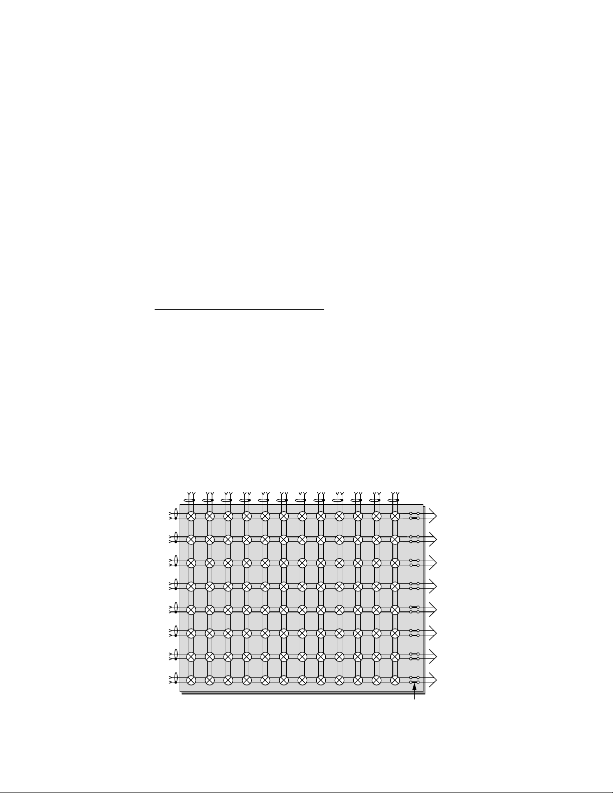
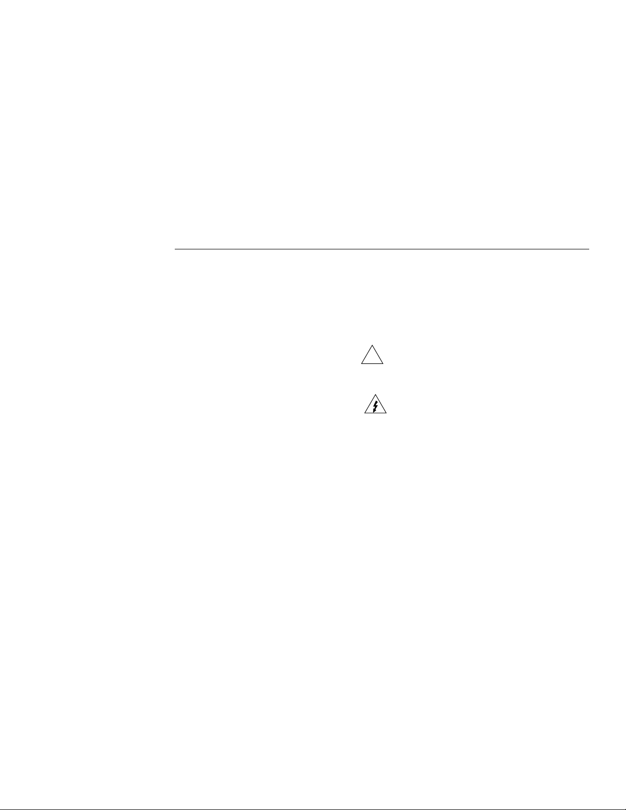
A simplified schematic of the Model 7077 matrix card is
shown in Figure 2-1 (View A). Each of the 96 crosspoints is
made up of a two-pole switch. By closing the appropriate
crosspoint switch, any row can be connected to any column
in the same matrix. The columns of every Model 7077 matrix
card are referred to as columns 1 through 12, except where
noted.
The Model 707 or 708 recognizes 12 columns for programming purposes. The crosspoint assignments for the matrix
card are shown in Figure 2-1 (View B). To connect ROW A
to COLUMN 10, the Model 707 or 708 must be programmed
to close crosspoint A10 (R O W A, COLUMN 10). T o connect
ROW E to COLUMN 10, crosspoint E10 must be closed.
The crosspoint assignments in Figure 2-1 (View B) are valid
regardless of how the card is configured.
When installed in a multiple card switching matrix (Model
707), the column number assignments for programming the
Model 707 are determined by the switching matrix slot the
matrix card is installed in. For example, the column number
assignments of a matrix card installed in slot 4 of the switching matrix are numbered 37 through 48. Column number assignments for all six switching matrix slots are listed in T able
2-1.
Table 2-1
Model 7077 column number assignments
Matrix column
Card location
Slot 1
Slot 2
Slot 3
Slot 4
Slot 5
Slot 6
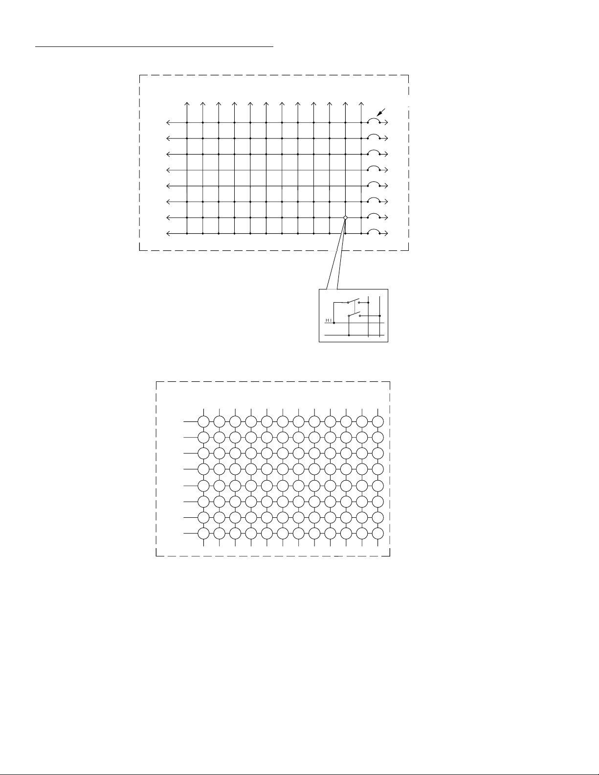
In Figure 2-1 (View A), there are backplane jumpers located
on the matrix card. With the jumpers installed, the matrix
card is connected to the backplane of the Model 707 or 708
for matrix expansion (see paragraph 2.5). With the jumpers
removed, the matrix card is isolated from other cards or
switching matrices. The physical location on the board of
these jumpers is shown in Figure 2-2.
numbers
1 through 12
13 through 24
25 through 36
37 through 48
49 through 60
61 through 72
2-1
Page 15
Operation
ROW
1234567891011 12
COLUMN
A
B
C
D
E
F
G
H
View A - Simplified schematic
Crosspoint (1 of 96)
H I
LO
Backplane
Jumper Sets (8)
1234567891011 12
A1
A
B
C
D
A2 A3 A4 A5 A6 A7 A8 A9 A10 A11 A12
B1
B2 B3 B4 B5 B6 B7 B8 B9 B10 B11 B12
C1
C2 C3 C4 C5 C6 C7 C8 C9 C10 C11 C12
D1
D2 D3 D4 D5 D6 D7 D8 D9 D10 D11 D12
ROW
COLUMN
E1
E
F
G
H
Note : Crosspoint assignments of Model 7077 Matrix Card shown above apply when installed in:
Model 708 Switching Matrix - Stand-alone or master of multi-unit configuration or
Model 707 Switching Matrix - Slot one of stand-alone or master of multi-unit configuration.
E2 E3 E4 E5 E6 E7 E8 E9 E10 E11 E12
F1
F2 F3 F4 F5 F6 F7 F8 F9 F10 F11 F12
G1
G2 G3 G4 G5 G6 G7 G8 G9 G10 G11 G12
H1
H2 H3 H4 H5 H6 H7 H8 H9 H10 H11 H12
View B - Crosspoint assignments
Figure 2-1
Model 7077 simplified schematic and crosspoint assignments
2-2
Page 16
Operation
Figure 2-2
Simplified component layout
Backplane
Jumpers
2-3
Page 17
Operation
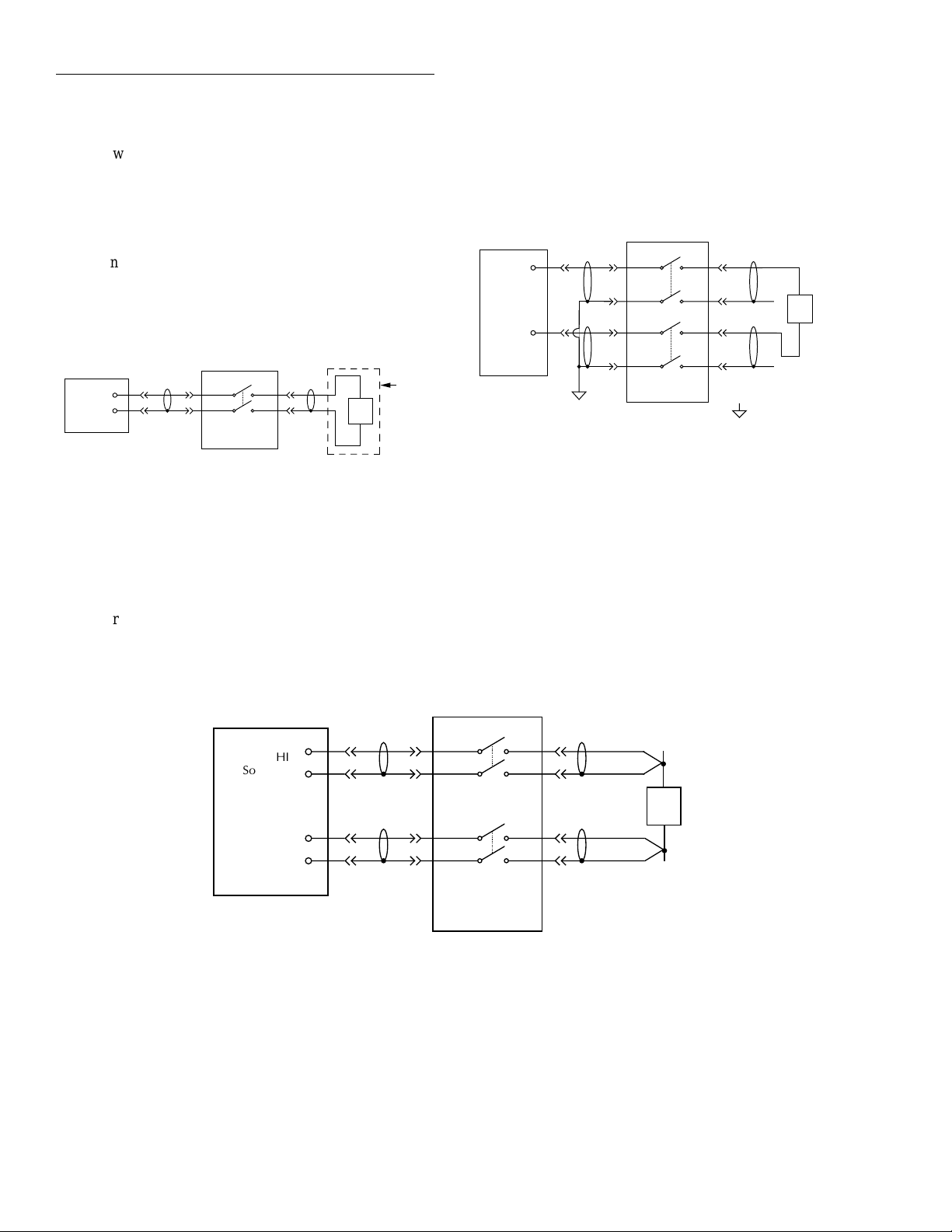
2.3 Typical matrix switching schemes
The following paragraphs describe basic switching schemes
that are possible with a two-pole switching matrix.
2.3.1 Single-ended switching
In the single-ended switching configuration, the source or
measure instrument is connected to the DUT through a single pathway as shown in Figure 2-3. The closure of a single
crosspoint will connect an instrument to a DUT.
ROW COLUMN
HI
LO
Source or
Measure
H
L
7077
DUT
Figure 2-3
Single-ended switching example (using 4801 coaxial cable)
Shield
confined to the same matrix crosspoint. Each terminal of the
instrument can be connected to any matrix crosspoint. The
LO terminals of the matrix card are used as a shield. The closure of a single crosspoint will not connect an instrument to
a DUT.
ROWS COLUMNS
HI
LO
Source or
Measure
H
L
H
L
7077
DUT
System Common
Figure 2-4
Differential switching example
2.3.3 Sensing
2.3.2 Differential switching
The differential or floating switching configuration is shown
in Figure 2-4. The advantage of using this configuration is
that the terminals of the source or measure instrument are not
ROWS COLUMNS
Sense HI
Source HI
Sense LO
Source LO
Source or
Measure
Figure 2-5
Sensing example
Figure 2-5 shows how the matrix card can be configured to
use instruments that have remote sensing capability. Sensing
is used to cancel the effects of matrix card path resistance
(<1.5) and the resistance of external cabling. Remote sensing
should be used when path resistance needs to be considered.
H
L
DUT
H
L
7077
2-4
Page 18
Operation
2.4 Connections
CAUTION
To prevent damage (not covered by the
warranty), do not exceed the maximum
allowable limits of the Model 7077.
Maximum signal levels are listed in the
specifications located at the front of the
manual.
All rows and columns of the Model 7077 Matrix Card are
connected to the BNC connectors mounted on the rear panel
of the matrix card when shipped. One receptacle is provided
for each row connection (rows A through H) and one for each
column connection (columns 1 through 12).
ROWS
1
A
2
B
C
D
E
F
G
H
3
4
5
6
7
8
9
10
11
12
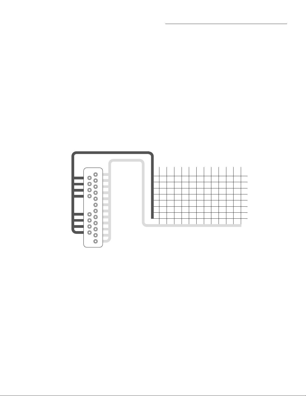
BNC connector identification is provided in Figure 2-6. Each
BNC connector is internally connected to the adjacent corresponding row or column.
Cable connections
Available Keithley cables and connectors for customized
user supplied terminations are summarized in Table 2-2.
WARNING
To avoid electrical shock that could result in injury or death, ALWAYS remove
power from the entire system (Model
707 or 708, test instruments, DUT, etc.)
and discharge any capacitors before
connecting or disconnecting cables from
the matrix card.
1 2 3 4 5 6 7 8 9 10 11 12
A
B
C
D
E
F
G
H
COLUMNS
Model 7077
Figure 2-6
BNC connector identification
2-5
Page 19

Operation
Table 2-2
Available Keithley cables and connectors
Model or part
number Description
237-ALG-2
4801
4802-10
4803
4804
4851
6147
7051-2 BNC to
BNC cable
7051-5 BNC to
BNC cable
7051-10 BNC to
BNC cable
7754-3 BNC to alligator cable
7755 50 Ω feedthrough terminator
Use the following procedure to connect a BNC cable to the
matrix card:
1. Install the matrix card in the Model 707 or 708 Switching Matrix (see paragraph 4.3).
2. Push the cables onto the appropriate receptacle of the
matrix card.
3. Tighten the BNC connector to secure it to the panel. The
same procedure can be used for connecting the cable
plug to a test fixture receptacle.
Low noise triax cable 2m (6.6ft.) in
length with a 3-slot male triax connector on one end and three alligator
clips on the other.
Low noise coaxial cable 1.2m
(48in.) in length with male BNC
connectors on both ends.
Low noise coaxial cable 3m (10ft.)
in length with a male BNC connector at one end and unterminated at
the other end.
Low noise cable kit. Includes 50ft.
of low noise coaxial cable, 10 male
BNC connectors, and 5 female BNC
chassis-mount connectors.
Male BNC to female triax adapter.
BNC shorting plug.
Male triax to female BNC adapter.
The Model 7051-2 is a 50 Ω
BNC cable (RG-58C) 1.5m (5ft.) in
length.
The Model 7051-5 is a 50 Ω BNC to
BNC cable (RG-58C) 1.5m (5ft.) in
length.
The Model 7051-10 is a 50 Ω BNC
to BNC cable (RG-58C) 3.0m
(10ft.) in length.
The Model 7754-3 is a 0.9m (3ft.)
50 Ω cable (RG-58C) terminated
with a BNC plug on one end and
two alligator clips on the other end.
The Model 7755 is a BNC to BNC
adapter terminated with a 50 Ω resistor.
BNC to
Modifying BNC terminated
A common way to use the standard cable is to cut it at a convenient length. The result is two cables that are both unterminated at one end. The unterminated ends of the cables can
then be connected to instrumentation and the DUT, and the
other ends can mate to the ROW and COLUMN BNC connectors of the matrix card.
WARNING
Due to the large amount of wiring that
switching systems contain, check that
both ends of the coaxial cable to be cut
are disconnected from instruments or
DUTs prior to performing this procedure. Cutting a connected cable may
cause severe injury or death due to electric shock.
2.5 Matrix expansion
By using additional matrix cards in the Model 707 or additional switching matrices in the Model 708, larger matrices
can be configured through the backplane of the Model 707 or
708. Therefore, unless otherwise noted, the examples provided in the following paragraphs assume the Model 7077
backplane jumpers are installed.
2.5.1 Backplane row jumpers
Matrix row expansion can be done through the backplane of
the Model 707 or 708 Switching Matrix. As explained in
paragraph 2.2, the Model 7077 has eight sets of backplane
jumpers that connect the rows of the matrix card to the
switching matrix backplane.
Model 707 switching matrix
The set of backplane jumpers located in the Model 707
Switching Matrix must be considered when building larger
matrices through rows. With the switching matrix backplane
jumpers installed, the rows of all switching matrix slots are
connected together. W ith these jumpers removed, the ro ws of
Model 707 Switching Matrix slots 1, 2, and 3 are isolated
from the rows of slots 4, 5, and 6.
2-6
Page 20

Figure 2-7
Backplane jumper configuration (factory default)
W125
W126
G
H
H
W127
W128
H H
W129
W130
H H
W131
W132
H H
W133
W134
H H
W135
W136
H H
W137
W138
H H
W139
W140
H H
Model 7077
To 3-pole
general purpose
backplane of
Model 707 or
Model 708
ROW A
ROW B
ROW C
ROW D
ROW E
ROW F
ROW G
ROW H
G
L
L
G
G
L
G
G
L
G
G
L
G
G
L
G
G
L
G
G
L
G
G
NOTE
• The Model 707 Switching Matrix
is shipped with its backplane row
jumpers installed. Some configurations require these backplane
row jumpers to be removed. The
procedure for removing these
jumpers is in the Model 707 Instruction Manual.
• The Model 708 Switching Matrix
does not have backplane row
jumpers. It is a one-slot switching
matrix.
Backplane compatibility considerations
The Model 7077 may be incompatible with other card types
when expansion is through the backplane. For example, in
some test systems it may be necessary to connect LO of the
Model 7077 (which is a two-pole card) to LO of a three-pole
card. As shipped, the Model 7077 backplane row jumpers
connect the LO signal paths to the GUARD terminals of the
three-pole general purpose backplane of the Model 707 or
708 switching matrix. The LO signal paths of the other card
are connected to the LO backplane terminals of the Model
707 or 708. With this configuration, LO of the Model 7077
cannot be routed to LO of the other card.
Operation
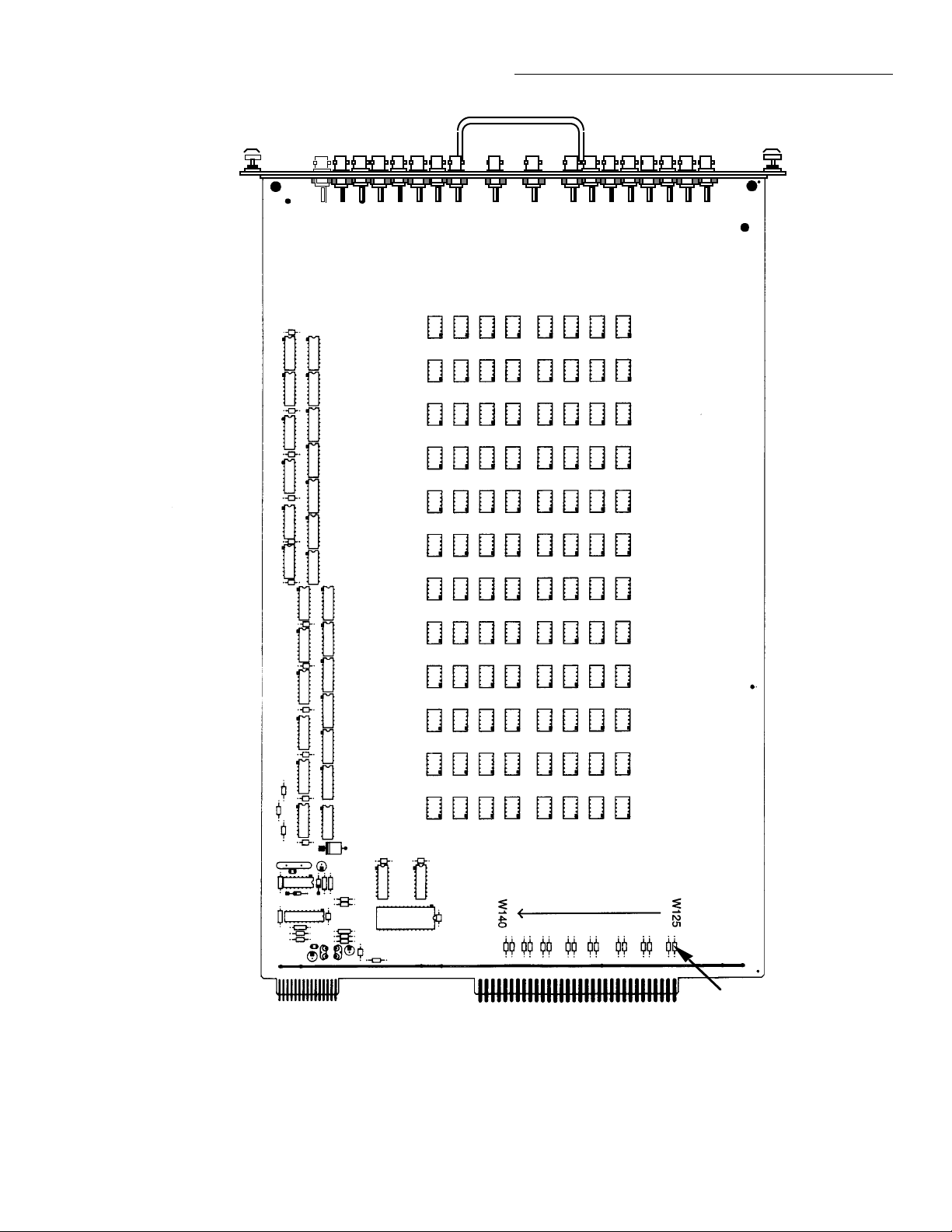
The Model 7077 provides flexibility by allowing the backplane route of the guard signal paths to be altered. The backplane row jumpers are shown in Figure 2-7. They have circuit
designations W125 through W140. The odd circuit designations (W125, W127, W129, W131, W133, W135, W137 and
W139) identify the LO jumpers of the card. These jumpers
connect the LO signal paths of the card to the GUARD backplane terminals of the Model 707 or 708. Adjacent to each HI
jumper (identified by the even circuit designations) are holes
in the pc-board to accommodate a jumper. By moving the
guard jumpers to these locations, the matrix card LO paths
will connect to the low backplane terminals of the Model 707
or 708.
Internal modifications to the matrix
card should only be performed by qualified service personnel familiar with
standard safety precautions.
Solder operations require that the pcboard be cleaned. Refer to the precautions contained in paragraph 4.2.
WARNING
CAUTION
A simplified schematic diagram of the Model 707 backplane
is shown in Figure 2-8. The segmented line represents backplane connections for one matrix row . Each empty slot is isolated by the open backplane connections. Row connections
from one slot to an adjacent slot are accomplished through
the jumpers on the Model 7077 Matrix Cards.
Model 707
Backplane
Slot
Slot
1
2
Slot
3
Slot
4
Slot
5
Slot
6
Figure 2-8
Model 707 backplane configured for row expansion
2-7
Page 21

Operation
As shown in Figure 2-7, the backplane disconnect jumper is
positioned to connect the matrix row to the next higher and
lower switching matrix slot. To isolate the matrix row from
the backplane, remove the jumper. Refer to the Model 707
Switching Matrix Instruction Manual for more information
on configuring the Model 707 Switching Matrix backplane
disconnect jumpers.
NOTE
The backplane used in the Model 707 and
708 Switching Matrices for the Model
7073 Matrix Cards is not used by any other switching matrix cards. This isolates
any Model 7077 Matrix Cards connected
through the backplane of a Model 707/708
Switching Matrix from Model 7073 Matrix Cards.
Table 2-3
Narrow matrix expansion*
Installed matrix cards Resulting matrix
1 card
2 cards
3 cards
4 cards
5 cards
6 cards**
* For the Model 707 Switching Matrix, backplane jumpers must
be in position 1 (refer to Model 707 Switching Matrix Instruction Manual), and cards must be installed with no empty slots
between them. This will keep the circuit through the backplane
serial link closed.
**Not applicable to the Model 708 Switching Matrix due to the
master/slave configuration having a maximum of five cards.
8 × 12
8 × 24
8 × 36
8 × 48
8 × 60
8 × 72
2.5.2 Narrow matrix expansion
When shipped from the factory, the jumpers on the card are
positioned to connect the rows into the backplane of a Model
707 or 708 Switching Matrix. Therefore, each Model 7077
card installed next to another Model 7077 in the switching
matrix extends the matrix by 12 columns (see Table 2-3). For
example, three cards installed in slots 1, 2, and 3 of the Model 707 will result in an 8 × 36 matrix. Figure 2-9 shows three
matrix cards installed in slots 1, 2, and 3. Cards must be installed in adjacent slots for the rows to be connected together .
Similarly, if a Model 708 Switching Matrix is externally expanded (three Model 708s connected through the backplane), installing the Model 7077 Matrix Card in each would
result in an 8 × 36 matrix. Refer to paragraph 2.5.5 for information on external mainframe matrix expansion for the
Model 708 Switching Matrix.
1
A
7077
ROWS
(Slot 1)
H
12 13 24 25 36
2.5.3 Wide matrix expansion
Configure wide matrices by connecting the columns of one
Model 7077 card to the columns of another Model 7077
card. An e xample of a wide matrix (16 × 12) is shown in Figure 2-10. Note that the rows of the two cards are isolated
from each other. Isolate each matrix card's ro ws by removing
jumpers to isolate each card.
The most convenient method for connecting columns of two
cards together is to use 12 BNC to BNC cables (Keithley
Model 7051) and 12 BNC “T” female, male, female adapters
(Pomona Model 3285). Connect the “T” adapters to the 12
columns of one card, and then connect the BNC cables from
the adapters to the columns of the other card. The extra BNC
connector on each adapter will then allow column connection to instrumentation or DUTs.
COLUMNS
7077
(Slot 2)
7077
(Slot 3)
Figure 2-9
Narrow matrix expansion (8
2-8
×
36)
Page 22

Operation
A
ROWS
H
A
ROWS
H
7077
(Slot 1)
112
37 48
7077
(Slot 4)
Figure 2-10
Wide matrix expansion (16 × 12)
Columns
Externally
Connected
Together
2.5.4 Partial matrix implementation
A fully implemented matrix provides a relay at each potential crosspoint. For example, a fully implemented 16 × 24
matrix utilizing four Model 7077s contains 384 crosspoints.
A partially implemented matrix is obtained by removing one
Model 7077 from the switching matrix (Figure 2-11). The
partial matrix is still 16 × 24, but contains only 288 crosspoints. An advantage of a partial matrix is that fewer matrix
cards are needed. Also, by incorporating a partial matrix into
the design of the matrix, specific devices can be isolated
avoiding direct connection with an accidental crosspoint closure. For example, a source in Figure 2-11 cannot be connected to DUT #2 with one “accidental” crosspoint closure.
Three specific crosspoints must be closed in order to connect
a source to DUT #2. Partial matrix expansion of a Model 708
Switching Matrix can be accomplished by externally expanding the matrix (three Model 708s, two connected
through the backplane, one connected externally through the
matrix columns). Refer to paragraph 2.5.5 for information on
external mainframe matrix expansion for the Model 708
Switching Matrix.
Measure #1
Measure #2
Source #1
Source #2
Figure 2-11
Partial matrix example (16 × 24)
DUT #1 DUT #2
112
A
7077
(Slot 1)
H
A
7077
(Slot 4)
H
13 24
Colum ns exte rnally
connected together
7077
(Slot 2)
2-9
Page 23

Operation
2.5.5 Mainframe matrix expansion
Model 707
Systems containing up to 30 matrix cards can be built by
daisy-chaining five Model 707 switching matrices together.
Using 30 Model 7077 matrix cards provides 2880
crosspoints.
Assuming all backplane jumpers are installed, connecting
the rows of a card in one mainframe to the rows of a card in
a second mainframe increases the number of columns in the
matrix. For example, if the rows of a 4 × 120 matrix in one
mainframe are connected to the rows of a 4 × 72 matrix in a
second mainframe, the resulting matrix would be 4 × 192.
See the Model 707 Instruction Manual for detailed information on daisy-chaining Model 707 mainframes. Table 2-4
summarizes possibilities for mainframe matrix expansion for
one Model 707 Switching Matrix. A maximum of 576 crosspoints can be contained in each Model 707 Switching Matrix.
Table 2-4
Mainframe matrix expansion — Model 707
struction Manual for detailed information on daisy-chaining
Model 708 Switching Matrices. Table 2-5 summarizes the
possibilities for mainframe matrix expansion for the Model
708 Switching Matrix.
Table 2-5
Mainframe matrix expansion — Model 708
Number of mainframe Resulting matrix
1
2
3
4
5
12
8 ×
8 × 24
8 × 36
8 × 48
8 × 60
2.6 Typical connection schemes
The following paragraphs provide typical connection
schemes for single card, multiple card, and multiple switching matrix configurations. A system using the matrix card
with a multiplexer card (Keithley Model 7075) is illustrated
to demonstrate versatility and compatibility.
Number of installed
matrix cards per
mainframe
1
2
3
4
5
6
Resulting matrix per
Model 707 Switching
Matrix
8 × 12
8 × 24
8 × 36
8 × 48
8 × 60
8 × 72
Model 708
Systems containing up to five Model 7077 Matrix Cards are
possible by daisy-chaining five Model 708 Switching Matrices together. Using five Model 7077 Matrix Cards provides
a maximum of 480 crosspoints (96 per switching matrix/matrix card).
The number of columns in the matrix can be increased by
connecting the rows of the card in one switching matrix to
the rows of the card in the second switching matrix, assuming all backplane jumpers are installed. For example, if the
rows of an 8 × 12 card in one switching matrix are connected
to the rows of an 8 × 12 card in a second switching matrix,
the result would be an 8 × 24 matrix. See the Model 708 In-
All examples show BNC cables. In many cases, these cables
are best used by cutting them in half, which provides twice
as many cables and allows direct connection to instrumentation and the DUT . Cables could be custom b uilt to better suit
a particular application.
2.6.1 Single card system
External connections for a single card system are made by
connecting instrumentation to matrix card rows using a BNC
cable for general purpose testing. Cutting one of these cables
in half provides two column cables that will connect directly
to the DUT. Figure 2-12 shows the connections of an example single card system. Instruments are connected to the
Model 7077 rows, and DUTs are connected to the Model
7077 columns and four of the rows (E through H).
2.6.2 Multiple card system
Figure 2-13 shows a system using two matrix cards. In this
configuration, the instrumentation and the DUT are both
connected to the columns of the matrix. In this example, the
instruments are connected to the rows (they only require six
pathways), and the DUTs are connected to the columns.
2-10
Page 24

Operation
Ins trum e nta tion
= BNC
Cables
ROWS
ROWS
1
A
2
B
3
C
4
D
5
6
7
8
E
9
F
10
G
11
H
12
7077 Matrix Card
COLUMNS
Test Fixture
Ins trum e nts
DUTs
DUT
DUTs
Simplified Equivalent Circuit
A
B
C
D
E
F
G
H
Figure 2-12
Single card example
2-11
Page 25

Operation
Model 707
Instr ume nts
Ins trum e nta tion
112
A
ROWS
COLUMNS
13 24 25 36 37 48
DUT
Test Fixture
DUTs
= BNC
Cables
H
Figure 2-13
Multiple card system example
Simplified Equivalent Circuit
2-12
Page 26

Operation
2.6.3 Multiple switching matrix system
Figure 2-14 shows a system using eight matrix cards, requiring two Model 707s daisy-chained together. In this configuration, instrumentation and DUTs are connected to matrix
card columns. A single cable is used to connect each row of
the master Model 707 Switching Matrix to the corresponding
row of the slave. Use a modified or custom cable as short as
possible especially if path resistance is a critical factor. Similarly in Figure 2-15, two Model 708 Switching Matrices are
daisy-chained together.
2.6.4 Matrix/multiplexer system
Figure 2-16 shows an example of how the Model 7077 is
used with a multiplexer card (Keithley Model 7075) in the
same test system. In this example, the Model 7077 is configured as an 8 × 12 matrix and the Model 7075 is configured as
a quad 1 × 24 multiplexer . In this test system, the matrix card
provides 24 columns for the DUT or additional instrumentation. By using the multiplexer card in the system, 96 additional test lines become available. Dif ferent multiplex er card
bank jumper/backplane jumper combinations in the Model
7075 can provide different pin outs for the same quad 1 × 24
multiplexer configuration. Different multiplexer configurations are easily accomplished. For example (refer to Figure
2-16), removing backplane jumpers for rows C and F, and installing bank jumpers B to C and F to G will configure the
card as a dual 1 × 48 multiplexer.
2-13
Page 27

Operation
DUT
Test
Fixture
Model 707
(Master)
ROWS
COLUMNS
COLUMNS
COLUMNS
COLUMNS
COLUMNS
COLUMNS
COLUMNS
Model 707
(Slave)
= BNC
Cables
Ins tru m en tation
COLUMNS
Slo t 1 Slot 2 Slot 3 Slo t 4
DUT Instruments
Slo t 1 Slot 2
Figure 2-14
Multiple switching matrix example — Model 707
ROWS
DUT
Slo t 5 Slot 6
Simplified Equivalent Circuit
2-14
Page 28

DUT Test
Fixture
Instrumentation
Master/Slave
IN/OUT Cables
Equivalent Circuit
DUTs
(14 Connections)
1 2 3 4 5 6 7 8 9 10 11 12
Model 708 (Master)
BNC Cable - COLUMNS
BNC Cable - ROWS
Model 708 (Slave)
Simplified
Instrumentation
(10 Connections)
1 2 3 4 5 6 7 8 9 10 11 12
Operation
Master
Figure 2-15
Multiple switching matrix example – Model 708
A
B
C
D
E
F
G
H
Slave
2-15
Page 29

Operation
Jumpers
Bank
Model 7075
Backplane
707
Model 7077
Jumpers
Backplane
Jumpers
Backplane
12
11
10
9
8
7
6
COLUMN
5
4
3
2
1
12
12
12
1
1
1
A
B
C
12
12
12
12
1
1
E
D
12
12
2 11
1
12
24 Lines
2 11
1
12
2 11
24 Lines
1
12
2 11
1
12'
1'
12
F
E
1
1
1
F
H
G
12
2 11
1
12
24 Lines
2 11
1
12
Model 7075
2 11
1
12
24 Lines
2 11
1
Equivalent Circuit
H
G
Model 7077
1
A
F
A
B
E
C
D
H
G
Instrument
B
#1
C
Instrument
D
#2
Note: 7075 Configured as a quad 1X24 multiplexer
Figure 2-16
Matrix/multiplexer system
2-16
#1
Instrument
Row
#2
Instrument
instruments
to rows E through H at the
Note: Rows A through D jumpered
Page 30

3
Applications
3.1 Introduction
General applications to test thick film resistor networks and
transistors are provided in this section. These applications
are intended to demonstrate the versatility of using the matrix card in test systems.
3.2 Thick film resistor network testing
A dedicated matrix system for testing thick film resistor networks is shown in Figure 3-1. This system pro vides two different methods for checking thick films: four-wire resistance
measurement and voltage measurements using an applied
voltage. The Model 7077 used in this system is configured as
12 matrix.
an 8 ×
The system shown in Figure 3-1 tests three 3-element thick
films, but can be expanded to test more using additional
Model 7077 matrix cards. The Model 707 Switching Matrix
will accommodate six matrix cards, allowing up to 18 threeelement thick films to be tested. Daisy-chaining five Model
707s expands the system to 30 matrix cards allowing 90
three-element thick films to be tested. The Model 708
Switching Matrix accommodates one Model 7077 Matrix
Card. Daisy-chaining five Model 708s expands the system to
five matrix cards allowing up to 15 thick films to be tested.
3.2.1 Four-terminal ohms measurements
For general purpose testing, the Keithley Model 2000 can be
used to make 4-terminal resistance measurements of each
thick film. As shown in Figure 3-2, Ohms HI and Ohms
Sense HI are connected to one matrix row , and Ohms LO and
Ohms Sense LO are connected to another matrix row. With
this configuration, the resistance of each resistor element
and/or combined elements can be measured by closing the
appropriate crosspoints. In Figure 3-2, crosspoints A1 and
B3 are closed to measure the combined resistance of R1 and
R2.
The effects of thermal EMFs generated by relay contacts and
connections can be canceled using the offset compensated
ohms feature of the Model 2000. To compensate for thermal
EMFs, close two crosspoints (such as A1 and B1). This will
short the input of the Model 2000, enabling zero to cancel internal offset, and then enabling offset compensated ohms.
3-1
Page 31

Applications
Measure V or
4-terminal Ω
Source V
Model 2000
Model 230
Volts/Ohms HI
Ohms Sense HI
2000 MULTIMETER
Volts/Ohms LO
Ohms Sense LO
Output
Sense Output
Common
Sense Common
Ohms Sense
Volts Ohms
Model 7077 (8X12 Matrix)
TF-1 TF-2 TF-3
R1R2R
1 34567891011122
A
B
C
D
E
F
G
H
3
.
R1R2R
3
R1R2R
3
Figure 3-1
Thick film resistor network testing
Model 2000
Figure 3-2
Four-terminal Ω measurement
MULTIMETER
2000
Volts/Ohms HI
Ohms Sense HI
Volts/Ohms LO
Ohms Sense LO
Thick Film
R1R2R
HG1HG2HG3HG
H
A
L
H
B
L
Model 7077
3
4
R1R2R
HL LH HLHL
3
Ω
Model 2000
Equivalent Circuit
3-2
Page 32

Applications
3.2.2 Voltage divider checks
Thick film resistor networks that are going to be used as voltage dividers may be tested using voltages that simulate actual operating conditions. This is a particularly useful test for
resistor networks that have a voltage coefficient specification. The test system in Figure 3-1 uses the Keithley Model
230 to source voltage and the Keithley Model 2000 to measure voltage.
A consideration in these checks is the Model 2000 input impedance on voltage measurements. The input impedance is
diverted across the resistor being measured. The resultant divider resistance is the parallel combination of the resistor under test and the input impedance. As long as the input
impedance is much larger than the resistor being tested, the
error introduced into the measurement will be minimal. Minimum input impedance requirements are determined by the
accuracy needed in the measurement. The input impedances
of the Model 2000 are listed in T able 3-1. For better input impedance requirements, the Keithley Model 6517 Electrometer can be incorporated into the test system to measure
voltage.
Another factor considered when checking low voltage di viders is thermal EMFs generated by the matrix card. A matrix
card crosspoint can generate up to +5µV of thermal EMFs.
When making low voltage measurements be sure to account
for this additional error.
Table 3-1
Minimum input impedance — Model 2000 DMM
DC voltage range Minimum input resistance
100mV
1.0V
10V
100V
1000V
>10G Ω
>10G Ω
>10G Ω
10M Ω
10M Ω
Even though four-terminal connections are made at the Model 2000 and the resistor networks, the sense leads are internally disconnected from the input of the DMM when the
volts function is selected. The simplified test system is
shown in Figure 3-3.
The thick film is tested by applying a voltage across the resistor network and measuring the voltage across each resistor
element and/or across combined elements. In Figure 3-3,
crosspoints C1 and D4 are closed to apply voltage across the
network, and crosspoints A3 and B4 are closed to measure
the voltage drop across R3.
3.3 Transistor testing
A matrix system for testing dc parameters of transistors is
shown in Figure 3-4. This system uses a current source (K eithley Model 224), a voltage source (Keithle y Model 230) and
a DMM (Keithley Model 2000) to measure current and/or
voltage. This system tests three transistors, but can be expanded to test more by using additional Model 7077 Matrix
Cards. The Model 707 backplane will accommodate six matrix cards. Daisy-chaining five Model 707s expands the system to 30 matrix cards allowing 90 transistors to be tested.
Using a Model 708 Switching Matrix for this application,
three transistors can be tested. Expanding a system based on
the Model 708 Switching Matrix requires an additional Model 708 Switching Matrix for each additional Model 7077 Matrix Card. This expansion allows up to five Model 708
Switching Matrices to be daisy-chained, which allows 15
transistors to be tested.
NOTE
To check FETs or transistors that have
high gain or low power, equipment that
has lower offset current and higher impedance must be used. T o check these de vices,
the Keithley Model 7072 Semiconductor
Matrix Card and the Keithley Model 6517
Electrometer can be used.
3-3
Page 33

Applications
Model 2000
Measure V
2000 MULTIMETER
Output
Sense Output
Thick Film
R
1
HGHGHGHG
1234
H
HI
LO
A
L
H
B
L
H
C
L
R
2
R
3
Figure 3-3
Voltage divider checks
Model 230
Source V
Common
Sense Common
H
D
L
Model 7077
R
1
HLHLHLHL
R
2
+ -
V
Model 2000
Model 230
Equivalent Circuit
R
3
3-4
Page 34

Measure
V or I
Applications
1 3 4 5 6 7 8 9 10 11 122
2000 MULTIMETER
Volts HI
Volts LO
A
B
Model 2000
Source
V
Source
I
Figure 3-4
Transistor checking
Model 230
Model 224
Amps HI
Amps LO
Output
Common
HI
LO
C
D
E
F
G
H
Model 7077 Matrix Card
3-5
Page 35

Applications
3.3.1 Current gain checks
The dc current gain of a general purpose transistor can be
checked by configuring the transistor as a common emitter
amplifier. Figure 3-5 shows which crosspoints to close to
configure the amplifier circuit. In this circuit, gain is calculated by dividing collector current (measured by the Model
2000
A
B
I
Measure
V or I
224
Gain =
Equivalent Circuit
Model 2000
E
I
I
C
I
B
Volts HI
2000 MULTIMETER
Volts LO
Amps HI
2000) by base current (sourced by the Model 224). A profile
of the transistor operating characteristics can be obtained by
measuring the collector current over a specified voltage
range (V) for different base bias currents. For example, Figure 3-6 shows the characteristics of a typical NPN silicon
transistor at base bias currents (I) of 20µA, 40µA, 60µA and
80µA.
I
C
±
230
V
CE
HGHGHGHG
1 2 3 4
H
A
L
H
B
L
C
H
L
Source
V
Source
I
Figure 3-5
Transistor current gain checks
Model 230
Model 224
Amps LO
Output
Common
HI
LO
D
H
L
E
H
L
F
H
L
G
H
L
H
H
L
Model 7077
3-6
Page 36

Applications
10
8
6
, mA
c
I
4
2
012345
V , volts
CE
+80 µA
+60 µA
+40µA
+20 µA
I = 0
B
Figure 3-6
Common emitter characteristics of an NPN silicon
transistor
3.3.2 I
and V
E
measurements
BE
Matrix versatility is demonstrated in Figure 3-7 and Figure
3-8. The transistor is still configured as a common-emitter
amplifier, but the Model 2000 is removed from the collector
circuit and used to measure emitter current and base-to-emitter voltage. Notice that external connection changes are not
required. All connection changes are accomplished by control of matrix crosspoints. Care must be taken to prevent
crosspoints of rows B and D from being closed at the same
time.
3-7
Page 37

Applications
Measure
V or I
Source
V
224
Model 2000
Model 230
±
230
2000
A
E
I
HGHGHGHG
1 2 3 4
H
A
L
H
B
L
C
H
L
D
H
L
E
H
L
F
H
L
G
H
HI
L
H
H
LO
L
2000 MULTIMETER
Volts HI
Volts LO
Amps HI
Amps LO
Output
Common
Model 7077
Source
I
Figure 3-7
Transistor IE measurements
Model 224
Legend
Active path during current measurement
Inactive path during current measurement
3-8
Page 38

224
V
2000
Applications
V
BE
±
E
I
230
HLHLHLHL
1 2 3 4
Measure
V or I
Source
V
Source
I
Model 2000
Model 230
MULTIMETER
2000
Volts HI
Volts LO
Amps HI
Amps LO
Output
Common
H
A
L
H
B
L
C
H
L
D
H
L
E
H
L
F
H
L
G
H
HI
L
H
H
LO
L
Model 7077
Legend
Active path during current measurement
Inactive path during current measurement
Figure 3-8
Tr ansistor VBE measurements
Model 224
3-9
Page 39

4
Service Information
4.1 Introduction
This section contains information on servicing the Model
7077.
WARNING
The matrix configuration procedures
and installation in this section should
only be performed by qualified personnel who recognize shock hazards and
are familiar with the safety precautions
required to avoid possible injury. Review the safety precautions found at the
front panel this manual.
4.2 Handling and cleaning precautions
Because of the high impedance circuits on the Model 7077,
care should be taken when handling or servicing the card to
prevent possible contamination, which could degrade perfor mance. The following precautions should be taken when
handling the matrix card.
areas when the repair is complete using Genesolve or
the equivalent and clean cotton swabs. Take care not to
spread the flux to other areas of the circuit board. Once
the flux has been removed, swab only the repaired area
with methanol, and then blow-dry the board with dry nitrogen gas.
• T o av oid dirt build-up, operate the switching matrix and
matrix card in a clean environment. If the card becomes
contaminated, it should be thoroughly cleaned.
• After cleaning, the card should be placed in a 50 ° C low
humidity environment for several hours.
CAUTION
Do not store the card by leaning it
against an object (such as a wall) with its
edge connectors in contact with a contaminated surface (such as the floor).
The edge connectors will become contaminated, and tapes and solder connections on the pc board may break as the
card bends. ALWAYS store the card (in
its anti-static bag) in the original shipping carton.
• Do not store or operate the card in an environment
where dust could settle on the circuit board. Use dry nitrogen gas to clean dust off of the card if necessary.
• Handle the card only by the handle and side edges. Do
not touch any board surfaces, components, or edge connectors. Do not touch areas adjacent to electrical contacts. When servicing the card, wear clean cotton
gloves.
• If making solder repairs on the circuit board, use a flux
that is rosin RMA based. Remove the flux from these
4.3 Card installation and removal
WARNING
To avoid electrical shock that could result in injury or death, ALWAYS remove
power from the entire system (Model
707 or 708, test instruments, DUT, etc.)
and make sure stored energy in external
circuitry is discharged before performing any of the following:
4-1
Page 40

Service Information
1. Installing or removing the matrix cards from the switching matrix.
2. Connecting or disconnecting cables from the matrix
card. The pins of the cable connectors are easily accessible, which makes them extremely hazardous to handle
while power is applied.
3. Making internal changes to the card (such as removing
or installing jumpers).
Cable connections to the matrix card make it difficult to
install or remove the card from the switching matrix.
Therefore, it is advisable to install the card and then
make the cable connections. Cables should also be disconnected before removing the card from the switching
matrix.
Referring to Figure 4-1, perform the following procedure to
install the Model 7077 Matrix Card in the Model 707 or 708
Switching Matrices.
CAUTION
Contamination will degrade the performance of the matrix card. To avoid contamination, always grasp the card by
the handle and side edges. Do not touch
the card edge connectors, board surfaces, or components. Do not touch areas
adjacent to the electrical contacts on the
connectors.
WARNING
Both spring loaded panel fasteners must
be secured to ensure a proper chassis
ground connection between the matrix
card and the switching matrix. Failure
to properly secure this ground connection may result in personal injury or
death due to electric shock.
Model 707 — W ith the relay side of the matrix card fac-
ing the fan and the card's top and bottom edges seated in
the switching matrix card edge guides, feed the card
completely into the switching matrix (Figure 4-1, View
A). Secure the matrix card in the switching matrix by
tightening both spring loaded mounting screws.
Model 708 — W ith the relay side of the matrix card fac-
ing upwards and the card's top and bottom edges seated
in the switching matrix card edge guides, feed the card
completely into the switching matrix (Figure 4-1, View
B). Secure the matrix card in the switching matrix by
tightening both spring loaded mounting screws.
4. Connect cables to the matrix card as required. Refer to
Section 3 for sample applications.
Card removal
Card installation
WARNING
Turn off system power before installing
or removing matrix cards.
1. Turn the switching matrix off.
2. Select a slot in the switching matrix and remove cover
plate and mounting screws (Figure 4-1).
3. Install the Matrix Card.
WARNING
Turn off all system power before installing or removing matrix cards.
1. Turn the switching matrix(es) off.
2. Remove all cables from the matrix card.
3. Remove the matrix card from the switching matrix by
loosening both spring loaded panel fasteners and sliding
matrix card out of the switching matrix.
4. Install cover plate with mounting screws (Figure 4-1).
4-2
Page 41

g
Service Information
Panel Fasteners
Fan
Model 7077
Matrix Card
View A - Matrix card installation in a Model
707 Switchin
Matrix
Card Handle
Model 707 Switching Matrix
Spring-Loaded
Mounting Screws
Figure 4-1
Matrix card installation
M
A
D
E
I
N
U
.
S
.
A
.
E
X
T
T
R
I
G
I
N
P
U
T
Mounting
Screws
View B - Matrix card installation in a
Model 708 Switching Matrix.
Model 7077 Matrix Card
Model 708
WA
R
N
I
N
G
:
N
O
I
N
T
E
R
N
A
L
O
S
P
E
E
R
R
V
A
I
C
T
E
O
R
B
Y
S
E
Q
R
U
V
I
A
N
I
C
L
S
A
I
F
T
B
I
R
E
L
U
D
E
M
S
P
A
E
E
N
R
R
V
T
T
S
I
C
I
N
.
P
E
T
R
P
E
O
E
R
T
R
N
E
S
A
C
O
L
T
N
L
I
O
Y
N
N
E
F
L
U
A
S
O
G
W
E
N
A
I
D
T
L
I
N
.
Y.
H
F
S
O
S
T
A
R
F
M
I
C
R
E
O
E
N
T
H
Y
T
A
P
I
N
Z
E
A
U
A
R
E
N
D
D
D
,
R
R
E
A
P
T
M
A
S
T
E
R
/
S
L
M
A
A
V
S
E
T
E
R
/
S
L
A
V
E
M
A
T
R
I
X
R
E
A
D
Y
O
U
T
P
U
T
I
N
O
U
T
D
I
G
I
T
A
L
I
N
P
U
T
D
I
G
I
T
A
L
O
U
T
P
U
T
I
E
E
E
-
4
8
8
I
N
T
E
R
F
A
C
E
L
I
A
N
C
G
E
.
F
U
S
E
L
I
N
E
R
A
T
I
N
G
9
0
2
5
0
V
5
0
,
6
0
H
Z
5
0
V
A
M
A
X
F
U
S
E
R
A
T
I
N
G
2
A
,
2
5
0
V
3
2
4
1
5
3
2
0
4
1
6
9
5
7
0
8
6
9
7
8
I
E
E
E
4
8
8
A
D
D
R
E
S
S
Relays
Note: Rear panel installation into Model 708,
is shown. Front panel installation is similar.
4-3
Page 42

Service Information
4.4 Performance verification
The following paragraphs discuss performance verification
procedures for the Model 7077, including path resistance,
offset current, contact potential, and isolation.
WARNING
The performance verification procedures contained in this section are intended for use by experienced service
personnel. Do not perform these procedures unless qualified to do so. Failure
to recognize and observe normal safety
precautions could result in personal injury or death.
The procedures described in this section are lengthy due to
the large number of row and column combinations checked.
As an alternative to this extensi ve testing, it may be desirable
to check only those paths that are going to be used, or those
that are suspected of being faulty.
tamination, always grasp the card by
the handle and side edges. Do not touch
the card edge connectors, board surfaces, or components. On plugs and receptacles, do not touch areas adjacent to the
electrical contacts.
NOTE
Failure of any performance verification
test may indicate that the matrix card is
contaminated. See paragraph 4.2 for card
cleaning instructions. If the test still fails
after cleaning, clean the backplane (see
the Switching Matrix Instruction Manual).
4.4.1 Environmental conditions
All verification measurements should be made at an ambient
temperature between 18 ° and 28 ° C and at a relative humidity
of less than 70%.
With the Model 7077's backplane jumpers installed, the performance verification procedures must be performed with
only one matrix card (the one being checked) installed in a
Model 707/708 Switching Matrix. The switching matrix
must not be daisy-chained to another switching matrix.
These conditions do not apply if the Model 7077's backplane
jumpers have been removed.
CAUTION
Contamination will degrade the performance of the matrix card. To avoid con-
Table 4-1
Verification equipment
Keithley model or
Description
DMM
Electrometer with voltage source
Nanovoltmeter
Triax cable (unterminated)
Low thermal cable (unterminated)
part number Specifications Applications
Model 2000
Model 6517
Model 182
Model 7025
Model 1484
4.4.2 Recommended equipment
Table 4-1 summarizes the equipment necessary for performance verification and an application for each unit.
NOTE
Do not use the Model 7070 Universal
Adapter Card as an extender card to verify
performance of the Model 7077. The
Model 7077 must be installed in the
switching matrix.
100Ω, .008%
20pA-200pA, 1%
100V source, .15%
2mV, 0.015%
—
—
Path resistance
Offset current path isolation
Contact potential
Offset current
Contact potential
4-4
Page 43

Ω
Service Information
4.4.3 Path resistance tests
NOTE
Refer to the performance verification
overview (paragraph 4.4) prior to performing this procedure.
1. Remove all power from the switching matrix and
switching matrix cards.
2. Install the Model 7077 Matrix Card in the switching matrix.
NOTE
Install the Model 7077 Matrix Card in slot
one of the Model 707/708 Switching Matrix.
3. Connect all column terminals (columns 1 through 12) of
the Model 7077 together (Figure 4-2) forming one common terminal.
4. Set the Model 2000 to the 100 Ω range for Ω 4 measurements.
5. Connect the four test leads to the INPUT and SENSE
4 WIRE inputs of the Model 2000. Make sure the
Model 2000 is set appropriately for front panel or rear
panel inputs.
6. Short the four test leads together and zero the Model
2000. Leave zero enabled for the entire test.
7. Connect the Ohms HI and Ohms Sense HI leads from
the Model 2000 to the common terminal (refer to step
3). Make the physical connections at columns 1 through
12 as shown in Figure 4-2.
8. Connect the Ohms LO and Ohms Sense LO leads from
the Model 2000 to the high terminal (marked H in Figure 4-2) of ROW A.
9. Turn on the switching matrix and check the high terminals’ path resistance.
A. Program the switching matrix to close crosspoint
A1. Verify that the resistance of this path is <1.5 Ω .
B. Open crosspoint A1, and close crosspoint A2. Verify
that the resistance of this path is <1.5 Ω . Repeat this
procedure for the remainder of row A’s high terminal column paths (columns 3 through 12).
10. Turn of f the switching matrix and connect the Ohms LO
and Ohms Sense LO leads from the Model 2000 to the
low terminal (marked L in Figure 4-2) of ROW A.
11. Turn on the switching matrix and check the low terminals’ path resistance.
A. Program the switching matrix to close crosspoint
A1. Verify that the resistance of this path is <1.5 Ω .
B. Open crosspoint A1, and close crosspoint A2. Verify
that the resistance of this path is <1.5 Ω . Repeat this
procedure for the remainder of row A’s low terminal
column paths (columns 3 through 12).
12. Repeat steps 8 through 11 for the remainder of the matrix card’s rows (rows B through H).
4-5
Page 44

Service Information
2000 MULTIMETER
Ohms Sense HI
Ohms HI
Ohms LO
Jumpers
Model 2000
(Measure 4-wire ohms)
Ohms
Sense LO
Note : Setup shown is configured
to test the high (H) terminal
of row A through crosspoints
A1 through A12.
1 3 4 567 89
H
A
L
B
C
D
E
F
G
H
Figure 4-2
Path resistance testing
4.4.4 Offset current tests
Offset current tests check leakage current from high (HI) to
guard (L) chassis (common mode) and from high (HI) and
guard (L) (differential) for each pathway . These tests are performed by measuring the leakage current with an electrometer. In the following procedure, the Model 6517 is used to
measure leakage current.
Referring to Figure 4-3, perform the following procedure to
check offset current:
1. Remove all power from the switching matrix and
switching matrix cards.
2. Install the matrix card in the Model 708 or in slot 1 if using the Model 707.
3. Connect the Model 6517 to ROW A of the matrix card
as shown in Figure 4-2.
10
11 122
H
G
H
G
H
G
H
G
H
G
H
G
H
G
H
G
Model 7077
4. On the Model 6517, select the 200pA range, and enable
zero check and then zero correct. Leave zero correct enabled for the entire procedure.
5. Turn on the Model 707/708 Switching Matrix.
6. Program the Model 707/708 to close crosspoint A1.
7. On the Model 6517, disable zero check and verify that it
is <100pA. This measurement is the leakage current of
the pathway.
8. On the Model 6517, enable zero check. On the Model
707/708, open crosspoint A1.
9. Repeat steps 6 through 8 to check the remaining pathways (crosspoints A2 through A12) of the row.
10. Connect the Model 6517 to ROW B and repeat steps 6
through 9 to check crosspoints B1 through B12.
11. Repeat step 10 to check ROWS C through G.
12. To check differential offset current, connect the Model
6517 to RO W A as shown in Figure 4-4 and repeat steps
5 through 12.
4-6
Page 45

WARNING:NO INTERNAL OPERATOR SERVICABLE PARTS,SERVICE BY QUALIFIED PERSONNEL ONLY.
WARNING:NO INTERNAL OPERATOR SERVICABLE PARTS,SERVICE BY QUALIFIED PERSONNEL ONLY.
CAUTION:FOR CONTINUED PROTECTION AGAINST FIRE HAZARD,REPLACE FUSE WITH SAME TYPE AND RATING.
CAUTION:FOR CONTINUED PROTECTION AGAINST FIRE HAZARD,REPLACE FUSE WITH SAME TYPE AND RATING.
WARNING:
NO INTERNAL OPERATOR SERVICABLE PARTS,SERVICE BY QUALIFIED PERSONNEL ONLY.
WARNING:
NO INTERNAL OPERATOR SERVICABLE PARTS,SERVICE BY QUALIFIED PERSONNEL ONLY.
CAUTION:
FOR CONTINUED PROTECTION AGAINST FIRE HAZARD,REPLACE FUSE WITH SAME TYPE AND RATING.
CAUTION:
FOR CONTINUED PROTECTION AGAINST FIRE HAZARD,REPLACE FUSE WITH SAME TYPE AND RATING.
Service Information
Model 237-ALG-2
Low Noise Triax Cable
INPUT
!
INPUT
250V PEAK
DIGITAL
LINE FUSE
LINE RATING
115V
50-60HZ
SLOWBLOW
50VA MAX
1/2A 90-125V
AC ONLY
1/4A 180-250V
IEEE-488
(CHANGE IEEE ADDRESS
WITH FRONT PANEL MENU)
TRIG LINK
I/O
Model 6517
(Measure Current)
Note : Setup shown is configured
to test ROW A pathways for
offset current.
Figure 4-3
Common mode offset current testing
Model 4802-10
Coaxial Cable
HI
H
L
LO
A
B
C
D
E
F
G
H
HG
1
345678
2
Model 7077
9101112
Model 237-ALG-2
Low Noise Triax Cable
INPUT
!
INPUT
250V PEAK
LINE FUSE
LINE RATING
115V
50-60HZ
SLOWBLOW
50VA MAX
1/2A 90-125V
AC ONLY
1/4A 180-250V
IEEE-488
(CHANGE IEEE ADDRESS
WITH FRONT PANEL MENU)
DIGITAL
TRIG LINK
I/O
Model 6517
(Measure Current)
Note : Setup shown is configured
to test ROW A pathways for
offset current.
Figure 4-4
Differential offset current testing
Model 4802-10
Coaxial Cable
HI
HI
LO
HG
1
H
A
L
345678
2
9101112
B
C
D
E
F
G
H
Model 7077
4-7
Page 46

Service Information
4.4.5 Path isolation tests
Path isolation tests check the leakage resistance (isolation)
between adjacent paths. A path is defined as the HIGH (H)
and LO (L) circuit from a row to a column that results from
closing a particular crosspoint. The test is performed by applying a voltage (+42V) across two adjacent paths and then
measuring the leakage current across the paths. The isolation
resistance is then calculated as R = V/I. In the follo wing procedure, the Model 6517 functions as both a voltage source
and an ammeter. In the V/I function, the Model 6517 internally calculates the resistance from the known voltage and
current levels and displays the resistance value.
1. Remove all power from the switching matrix and
switching matrix cards.
2. Install the Model 7077 in the Model 708 or in slot 1 of
the Model 707.
3. Connect the Model 6517 to RO WS A and B as shown in
Figure 4-5. Make sure the voltage source is in standby
and there are no other connections to the card.
4. On the Model 6517, select the 20pA range, and enable
zero check and then zero correct. Leave zero correct enabled for the entire procedure.
5. On the Model 6517, select the 200pA range, and release
zero check.
6. On the Model 6517, press suppress to cancel offset current, and then enable zero check.
7. On the Model 6517, set the voltage source for +42V, and
select the 20nA current range. Make sure the voltage
source is in standby.
8. Place the Model 6517 in the V/I measurement function.
9. Turn on the Model 707/708, and program it to close
crosspoints A1 and B2.
10. On the Model 6517, disable zero check, and press OPERATE to source +42V.
11. After allowing the reading on the Model 6517 to settle,
verify that it is >10G Ω . This measurement is the leakage
resistance (isolation) between RO W A, COLUMN 1 and
ROW B, COLUMN 2.
12. Enable zero check, and then place the Model 6517 in
standby.
13. Turn of f the Model 707/708, and mak e sure all power is
removed from the circuit.
14. Disconnect the Model 6517 from ROWS A and B. In a
similar manner, reconnect it to R OWS B and C (picoammeter high and voltage source low to ROW B and voltage source high and low to ROW C).
15. Turn on the Model 707/708, and program it to close
crosspoints B2 and C3.
16. On the Model 6517, disable zero check, and press
OPERATE to source +42V.
17. After allowing the reading on the Model 6517 to settle,
verify that it is >10G Ω .
18. Using Table 4-2, repeat steps 13 through 18 for the rest
of the path pairs starting with test number 3.
4-8
Page 47

Model 237-ALG-2
WARNING:
NO INTERNAL OPERATOR SERVICABLE PARTS,SERVICE BY QUALIFIED PERSONNEL ONLY.
WARNING:
NO INTERNAL OPERATOR SERVICABLE PARTS,SERVICE BY QUALIFIED PERSONNEL ONLY.
CAUTION:
FOR CONTINUED PROTECTION AGAINST FIRE HAZARD,REPLACE FUSE WITH SAME TYPE AND RATING.
CAUTION:
FOR CONTINUED PROTECTION AGAINST FIRE HAZARD,REPLACE FUSE WITH SAME TYPE AND RATING.
Table 4-2
Path isolation tests
Test no. Path isolation
Test equipment
locations
Crosspoints
closed
1
2
3
4
5
6
7
8
9
10
11
Row A, Col 1 to Row B, Col 2
Row B, Col 2 to Row C, Col 3
Row C, Col 3 to Row D, Col 4
Row D, Col 4 to Row E, Col 5
Row E, Col 5 to Row F, Col 6
Row F, Col 6 to Row G, Col 7
Row G, Col 7 to Row H, Col 8
Row G, Col 8 to Row H, Col 9
Row G, Col 9 to Row H, Col 10
Row G, Col 10 to Row H, Col 11
Row G, Col 11 to Row H, Col l2
Row A and Row B
Row B and Row C
Row C and Row D
Row D and Row E
Row E and Row F
Row F and Row G
Row G and Row H
Row G and Row H
Row G and Row H
Row G and Row H
Row G and Row H
A1 and B2
B2 and C3
C3 and D4
D4 and E5
E5 and F6
F6 and G7
G7 and H8
G8 and H9
G9 and H10
G10 and H11
G11 and H12
Low Noise Triax Cable
Source V and
measure V/I
250V PEAK
LINE FUSE
LINE RATING
115V
50-60HZ
SLOWBLOW
50VA MAX
1/2A 90-125V
AC ONLY
1/4A 180-250V
IEEE-488
(CHANGE IEEE ADDRESS
WITH FRONT PANEL MENU)
DIGITAL
TRIG LINK
I/O
!
INPUT
Model 6517
Note : Setup shown is configured to test isolation
between ROW A, COLUMN 1 and
ROW B, COLUMN 2.
Service Information
Model 4802-10
Coaxial Cable
HL
HI
HI
1
H
A
L
H
B
L
C
D
E
F
G
H
345678
2
9101112
Figure 4-5
Path isolation testing (guarded)
Model 7077
4-9
Page 48

Service Information
4.4.6 Differential and common model isolation
tests
Differential and common mode isolation tests check the
leakage resistance (isolation) between high (H) and guard
(G) (differential), and from high and guard to chassis (common mode) of every row and column. The tests are performed by applying a voltage (42V) across the terminals and
then measuring the leakage current. The isolation resistance
is then calculated as R = V/I. In the follo wing procedure, the
Model 6517 functions as a voltage source and an ammeter.
In the V/I function, the Model 6517 internally calculates the
resistance from the known voltage and current le vels and displays the resistance value.
1. Remove all power from the switching matrix and
switching matrix cards.
2. Install the Model 7077 in the Model 708 or in slot 1 of
the Model 707.
3. Connect the Model 6517 to ROW A as shown in Figure
4-6 to measure differential isolation. Make sure the voltage source is in standby and there are no other connections to the card.
4. On the Model 6517, select the 20pA range, and enable
zero check and then zero correct. Leave zero correct enabled for the entire procedure.
5. On the Model 6517, set the voltage source for +42V, and
select the 200nA current range. Make sure the voltage
source is still in standby.
6. Place the Model 6517 in the V/I measurement function
by pressing SHIFT OHMS.
7. Turn on the Model 707/708, but do not program any
crosspoints to close. All crosspoints must be open.
8. On the Model 6517, disable zero check, and press
OPERATE to source 42V.
9. After allowing the reading on the Model 6517 to settle,
verify that it is >1G Ω . This measurement is the leakage
resistance (isolation) of ROW A.
10. Place the Model 6517 in standby and enable zero check.
11. Program the Model 707/708 to close crosspoint A1.
12. On the Model 6517, disable zero check and press
OPERATE to source +42V.
13. After allowing the reading on the Model 6517 to settle,
verify that it is also >1G Ω . This measurement checks
the isolation of COLUMN 1.
14. Using T able 4-3 as a guide, repeat the basic procedure of
steps 11 through 14 for the rest of the columns and rows
(test numbers 3 through 32 of the table).
15. Place the Model 6517 in standby, and turn the Model
707/708 off.
16. Connect the Model 6517 to ROW A as shown in Figure
4-7, and repeat steps 8 through 16 to check common
mode isolation.
4-10
Page 49

WARNING:
NO INTERNAL OPERATOR SERVICABLE PARTS,SERVICE BY QUALIFIED PERSONNEL ONLY.
WARNING:
NO INTERNAL OPERATOR SERVICABLE PARTS,SERVICE BY QUALIFIED PERSONNEL ONLY.
CAUTION:
FOR CONTINUED PROTECTION AGAINST FIRE HAZARD,REPLACE FUSE WITH SAME TYPE AND RATING.
CAUTION:
FOR CONTINUED PROTECTION AGAINST FIRE HAZARD,REPLACE FUSE WITH SAME TYPE AND RATING.
Source V and
WARNING:NO INTERNAL OPERATOR SERVICABLE PARTS,SERVICE BY QUALIFIED PERSONNEL ONLY.
WARNING:NO INTERNAL OPERATOR SERVICABLE PARTS,SERVICE BY QUALIFIED PERSONNEL ONLY.
CAUTION:FOR CONTINUED PROTECTION AGAINST FIRE HAZARD,REPLACE FUSE WITH SAME TYPE AND RATING.
CAUTION:FOR CONTINUED PROTECTION AGAINST FIRE HAZARD,REPLACE FUSE WITH SAME TYPE AND RATING.
measure V/I
Model 237-ALG-2
Low Noise Triax Cable
!
INPUT
250V PEAK
115V
DIGITAL
TRIG LINK
I/O
LINE RATING
50-60HZ
50VA MAX
AC ONLY
IEEE-488
(CHANGE IEEE ADDRESS
WITH FRONT PANEL MENU)
Service Information
LINE FUSE
SLOWBLOW
1/2A 90-125V
1/4A 180-250V
HI
LO
HL
1
H
A
L
345678
2
9101112
Model 6517
Figure 4-6
Differential isolation testing
Model 237-ALG-2
Low Noise Triax Cable
!
INPUT
250V PEAK
115V
DIGITAL
TRIG LINK
I/O
LINE RATING
50-60HZ
50VA MAX
AC ONLY
IEEE-488
(CHANGE IEEE ADDRESS
WITH FRONT PANEL MENU)
LINE FUSE
SLOWBLOW
1/2A 90-125V
1/4A 180-250V
Model 4802-10
Coaxial Cable
HL
HI
H
LO
A
L
B
C
D
E
F
G
H
Model 7077
345678
2
1
9101112
Model 6517
(Measure Current)
Note : Electrometer high is connected
to chassis ground.
Figure 4-7
Common mode isolation testing
B
C
D
E
F
G
H
Model 7077
4-11
Page 50

Service Information
Table 4-3
Differential and common mode isolation test
Test no.
1
2
3
4
5
6
7
8
9
10
11
12
13
14
15
16
17
30
31
32
Differential or
common mode test
ROW A
COLUMN 1
COLUMN 2
COLUMN 3
COLUMN 4
COLUMN 5
COLUMN 6
COLUMN 7
COLUMN 8
COLUMN 9
COLUMN 10
COLUMN 11
COLUMN 12
ROW B
ROW C
ROW D
ROW E
ROW F
ROW G
ROW H
Crosspoints
closed
None
A1
A2
A3
A4
A5
A6
A7
A8
A9
A10
A11
A12
A1 and B1
A1 and C1
A1 and D1
A1 and E1
A1 and F1
A1 and G1
A1 and H1
4.5 Principles of operation
The following paragraphs discuss the basic operating principles for the Model 7077 and can be used when troubleshooting the matrix card. The schematic drawing of the matrix
card is shown in drawing 7077-106, located at the end of
Section 5.
4.5.1 Card identification
Identification coding and a matrix configuration table are
stored in erasable programmable read only memory
(EPROM). This information is sent to the Model 707/708 so
the switching matrix can determine which type of matrix
card is installed in a particular slot. This lets the Model 707/
708 send valid configuration data to the matrix card.
On power up, control line CARDSEL goes low turning on
the EPROM (U128). This control line and other control lines
from the Model 707/708 are buffered by U130. Lines CLK,
NEXT ADDR, and CLR ADDR along with counter U126
control the task of loading data from the EPROM into the
parallel to serial shift register (U127). Data sent from U130
to the Model 707/708 through the IDDATA line is strobed by
the CLK control line. The timing diagram in Figure 4-8
shows the first byte of identification data during the transfer
sequence. For subsequent bytes, the CLRADDR line stays
low.
4.5.2 Switching circuitry
Matrix configuration data is sent from the Model 707/708
through the RELA Y D AT A control line and is serially loaded
into the 12 shift registers (U114 through U125). The matrix
card relays configure when the registers receive the
STROBE signal from the Model 707/708. A relay is energized when a relay driver output (U100 through U113) is low
(connected to digital common). A driver output is low when
a “high” data bit is clocked (i.e., inverting drivers).
Figure 4-8
ID data timing diagram
4-12
CARDSEL
CLRADDR
NEXTADDR
CLK
IDDATA
D7 D6 D5 D4 D3 D2 D1 D0
Page 51

Service Information
4.5.3 Power up safeguard
To prevent relays from accidentally energizing and causing
possible damage during power up, a safeguard circuit has
been incorporated into the design. The protection circuit is
comprised of a dual NAND gate (U129) configured as a SET
or RESET flip-flop and an RC network (R102, C122 and
CR101). The time constant of the RC network keeps the output of the NAND gate low during the power up sequence.
This low signal is applied to the OE input of the shift registers keeping the relays de-energized. After the capacitor of
the RC network charges, a STROBE signal will then force
the output of the NAND gate high, allowing configured relays to energize.
4.6 Special handling of static-sensitive devices
CMOS and other high-impedance devices are subject to possible static discharge damage because of the high-impedance
levels in volved. The following precautions pertain specifically to static-sensitive devices. However, since many devices
in the Model 7077 are static-sensitive, it is recommended
that they are all treated as static-sensitive.
• Such devices should be transported and handled only in
containers specially designed to prevent or dissipate
static buildup. These devices will be received in antistatic containers made of plastic or foam. Keep them in
their original containers until ready for installation.
• Remove the devices from their protective containers
only at a properly grounded workstation. Ground yourself with a suitable wrist strap while working with these
devices.
• Handle the devices only by the body; do not touch the
pins.
• Any printed circuit board into which the device is to be
inserted must first be grounded to the bench or table.
• Use only anti-static type de-soldering tools and groundedtip soldering irons.
4.7 Troubleshooting
The Keithley Model 7070 Universal Adapter Card is an extender card that allows access to circuit components of the
Model 7077 during troubleshooting.
4.7.1 Recommended equipment
Table 4-4 summarizes the equipment necessary for general
troubleshooting.
Table 4-4
Recommended troubleshooting equipment
Description Application
DMM (Keithley 2000)
Dual-trace, triggered sweep
oscilloscope, dc to 50MHz
Extender card (Keithley
7070)
Measure dc voltage
Check clock and logic pulses
Allow circuit access
4.7.2 Troubleshooting procedure
In order to service the matrix card, it may be necessary to remove the bottom shield. The bottom shield is secured to the
matrix card by eight screws. Remove these scre ws and separate the shield from the pc-board. When reinstalling the
shield, make sure it is oriented such that the standoffs (staked
onto the shield) are positioned between the pc-board and the
shield.
T able 4-5 outlines troubleshooting procedures for the matrix
card.
CAUTION
Contamination will degrade the performance of the matrix card. To avoid contamination, always grasp the card by
the handle and side edges. Do not touch
the card edge connectors, board surfaces, or components. On connectors, do
not touch areas adjacent to the electrical
contacts.
If removing relays from the pc-board,
care must be taken to prevent traces
from breaking off the board. Using a solder sucker, make sure all solder is removed. Each relay pin must move freely
in the feed-through hole. Make sure
there are no burrs on the ends of the relay pins.
4-13
Page 52

Service Information
Table 4-5
Troubleshooting summary*
Step Items/component** Comment Required condition
1
W152
2
W155
3
W150
+6V supply
+5V supply
CLR ADDR line***
+6V dc
+5V dc
High logic pulse at the beginning of each card identification byte
transfer sequence (upon power up).
4
W151
5
W149
6
W154
7
W156
8
W157
9
W158
10
U100 through U113
NEXT ADDR line
Clk line
ID Data line***
Power up safeguard
RELAY DATA line
STROBE line
Relay drivers
Low logic pulse before each byte transfer.
1.79MHz clock
Card identification logic pulse train (on power up).
Remains low during power up.
Logic pulse train to load relay configuration registers.
High logic pulse to strobe relay configuration registers.
+6V for open crosspoints 0V for closed crosspoints. Note that pins 10
through 16, pin 10 on U100 and U107 is not connected.
*All measurements referenced to digital common (W153)
**W149 through W158 are jumpers located on the pc-board. See component location drawing (at end of Section 5) for jumper locations.
***See Figure 4-8.
4-14
Page 53

5
Replaceable Parts
5.1 Introduction
This section contains replacement parts information, schematic diagrams, and component layout drawings for the
Model 7077.
5.2 Parts list
The parts list for the Model 7077 is included in tables integrated with the schematic diagram and component layout
drawing. Parts are listed alphabetically in order of circuit
designation.
5.3 Ordering information
To place an order, or to obtain information concerning replacement parts, contact your Keithley representative or the
factory (see the inside front cover for addresses). When ordering parts, be sure to include the following information:
• Card model number (7077)
• Card serial number
• Part description
• Circuit description, if applicable
• Keithley part number
5.4 Factory service
If the card is to be returned to Keithley Instruments for repair ,
perform the following:
• Call the Repair Department at 1-800-552-1115 for a
Return Material Authorization (RMA) number.
• Complete the service form at the back of this manual
and include it with the card.
• Carefully pack the card in the original packing carton.
• Write ATTENTION REPAIR DEPARTMENT and the
RMA number on the shipping label.
NOTE
It is not necessary to return the switching
mainframe with the card.
5.5 Component layout and schematic
diagram
A component layout drawing and schematic diagram are included on the following pages integrated with the parts list.
5-1
Page 54

Replaceable Parts
Table 5-1
Model 7077 electrical parts list
Circuit designation Description Keithley part no.
C100-116
C117,118
C119
C120,121
C122
C123,124
CR100
CR101
CR102
J1001-1020
K100-195
R100
R101
R102
R103
R104
R105
U100-113
U114-125
U126
U127
U128
U129
U130
CAP,.1UF,20%,50V,CERAMIC
CAP,.01UF,20%,50V,CERAMIC
CAP,.01UF,10%,1000V,CERAMIC
CAP,270PF,20%,100V,CERAMIC/FERRITE
CAP, 47UF,10%,16V,ALUM ELEC
CAP, 10UF,-20+100%,25V,ALUM ELEC
DIODE,SILICON, 5400 (267-01)
DIODE,SILICON,IN4148 (DO-35)
DIODE,SCHOTTKY, IN5711
CONNECTOR
RELAY, MINI SIGNAL REL
RES,10K,5%,1/4W,COMPOSITION OR FILM
RES,200,5%,1/4W,COMPOSITION OR FILM
RES,47K,5%,1/4W,COMPOSITION OR FILM
RES,11K,5%,1/4W,COMPOSITION OR FILM
RES,5.1K,5%,1/4W,COMPOSITION OR FILM
RES,120K,5%,1/4W,COMPOSITION OR FILM
IC,DARLINGTON ARRAY ,2003
IC, 8 BIT SHIFT LAT REG,74HC4094
IC, 12 STAGE BINARY COUNTER,74HCT4040
IC,8-BIT PARALLEL TO SERIAL,74HCT165
EPROM PROGRAM
IC, QUAD 2 INPUT NAND, 74HCT00
IC, OCTAL BUFFER/LINE DRIVER, 74HC244
C-365-.1
C-237-.01
C-64-.01
C-386-270P
C-321-47
C-314-10
RF-34
RF-28
RF-69
CS-681-3
RL-163
R-76-10K
R-76-200
R-76-47K
R-76-11K
R-76-5.1K
R-76-120K
IC-206
IC-713
IC-545
IC-548
7077-800**
IC-399
IC-489
5-2
W100
W125-148, 151-155
W149,150, 156-158
**Order firmware revision of present ROM.
STIFFENER, BOARD
JUMPER
JUMPER
J-16
J-15
J-15
Page 55

Table 5-2
Model 7077 mechanical parts list
Description Keithley part no.
Replaceable Parts
4-40X1/4 PHILLIPS PAN HD SEMS SCREW (SHIELD TO PCB)
6-32X3/8LG. PHIL FLAT HD SCR (FOR MOUNTING HANDLE)
6-32X5/16PHIL PAN HD SEMS SCR (PANEL TO PCB)
6-32 PEM NUT
CONNECTOR
CONNECTOR, BNC
CONNECTOR HOUSING
HANDLE
REAR PANEL ASSEMBLY
SHIELD, BOTTOM
SOCKET,I.C. 28 PIN (FOR U128)
4-40X1/4PPHSEM
6-32X3/8PFH
6-32X5/16PPHSEM
FA-135
CS-236
CS-520
CS-270
HH-33-1
7077-303A
7075-306A
SO-69
5-3
Page 56

Page 57

Page 58

Page 59

Page 60

Index
A
Applications 3-1
B
Backplane row jumpers 2-6
Basic matrix configurations 2-1
C
Card identification 4-12
Card installation and removal 4-1
Component layout and schematic diagram
5-1
Connections 2-5
Current gain checks 3-6
D
Differential and common model isolation
tests 4-10
Differential switching 2-4
E
Environmental conditions 4-4
H
Handling and cleaning precautions 4-1
I
I
and V
E
Inspection for damage 1-2
Instruction manual 1-2
measurements 3-7
BE
M
Mainframe matrix expansion 2-10
Manual addenda 1-1
Matrix expansion 2-6
Matrix/multiplexer system 2-13
Multiple card system 2-10
Multiple switching matrix system 2-13
N
Narrow matrix expansion 2-8
O
Offset current tests 4-6
Operation 2-1
Optional accessories 1-2
Ordering information 5-1
R
Recommended equipment 4-4, 4-13
Replaceable parts 5-1
S
Safety symbols and terms 1-1
Sensing 2-4
Service information 4-1
Shipping contents 1-2
Single card system 2-10
Single-ended switching 2-4
Special handling of static-sensitive devices
4-13
Specifications 1-1
Switching circuitry 4-12
T
Thick film resistor network testing 3-1
Transistor testing 3-3
Troubleshooting 4-13
Troubleshooting procedure 4-13
Typical connection schemes 2-10
Typical matrix switching schemes 2-4
U
Unpacking and inspection 1-2
F
Factory service 5-1
Features 1-1
Four-terminal ohms measurements 3-1
G
General information 1-1
P
Partial matrix implementation 2-9
Parts list 5-1
Path isolation tests 4-8
Path resistance tests 4-5
Performance verification 4-4
Power up safeguard 4-13
Principles of operation 4-12
V
Voltage divider checks 3-3
W
Warranty information 1-1
Wide matrix expansion 2-8
i-1
Page 61

Service Form
Model No. Serial No. Date
Name and Telephone No.
Company
List all control settings, describe problem and check boxes that apply to problem.
❏
Intermittent
❏
IEEE failure
❏
Front panel operational
Display or output (check one)
❏
Drifts
Unstable
❏
❏
Overload
❏
Calibration only
Data required
❏
(attach any additional sheets as necessary)
Show a block diagram of your measurement system including all instruments connected (whether power is turned on or not).
Also, describe signal source.
❏
Analog output follows display
❏
Obvious problem on power-up
❏
All ranges or functions are bad
❏
Unable to zero
Will not read applied input
❏
❏
CertiÞcate of calibration required
❏
Particular range or function bad; specify
❏
Batteries and fuses are OK
❏
Checked all cables
Where is the measurement being performed? (factory, controlled laboratory, out-of-doors, etc.)
What power line voltage is used? Ambient temperature? °F
Relative humidity? Other?
Any additional information. (If special modiÞcations have been made by the user, please describe.)
Be sure to include your name and phone number on this service form
.
Page 62

Keithley Instruments, Inc.
28775 Aurora Road
Cleveland, Ohio 44139
Printed in the U.S.A.
 Loading...