

Page 1
MODEL 707
SWITCHING MATRIX
QUICK REFERENCE GUIDE
Page 2

Page 3
INTRODUCTION
This quick reference guide cOntai”S deScripfio”S Of Various
features and information concerning the operation of the
Model 707. Also included are programming examples using
“alio”S controllers.
01988, Keithley Instruments, 1°C.
Instruments Division
Document Number: 707-903-01 Rev. A
Cleveland. Ohio, U.S.A.
Page 4

Page 5
TABLE OF CONTENTS
SAFETYPRECAUTIONS ...................... 2
FRONT PANEL FAMlLlARlZATlON .............. 3
OlSPLAY MESSAGES,, ..................... 18
REAR PANEL FAM,L,ARlZATlON. .............. 20
,NSTALL,NG AND REMOVING CARDS .......... 25
MASTER,SLA”E SYSTEMS .................. 27
BASIC SWITCHING OPERATION. .............. 30
Selectins Make/Break and Break/Make Rows 31
Modifyilg a Relay Setup ............
storing Setup and Sending to Relays ...
IEEE-488 PROGRAMMING
Device-Dependent Commands ........
oata Formats .....................
Hit Key Commands ................
SRO Mask and Serial Poll Byte ........
staws Words. ....................
PROGRAMS ,.,..,......................
IBM PC/XT/AT with CEC PC < > 488
IBM PC,XT,AT with CEC PC< ,488 and ASYST
HP Mode, 9000 series 200,3OO.. 57
.............
Page 6
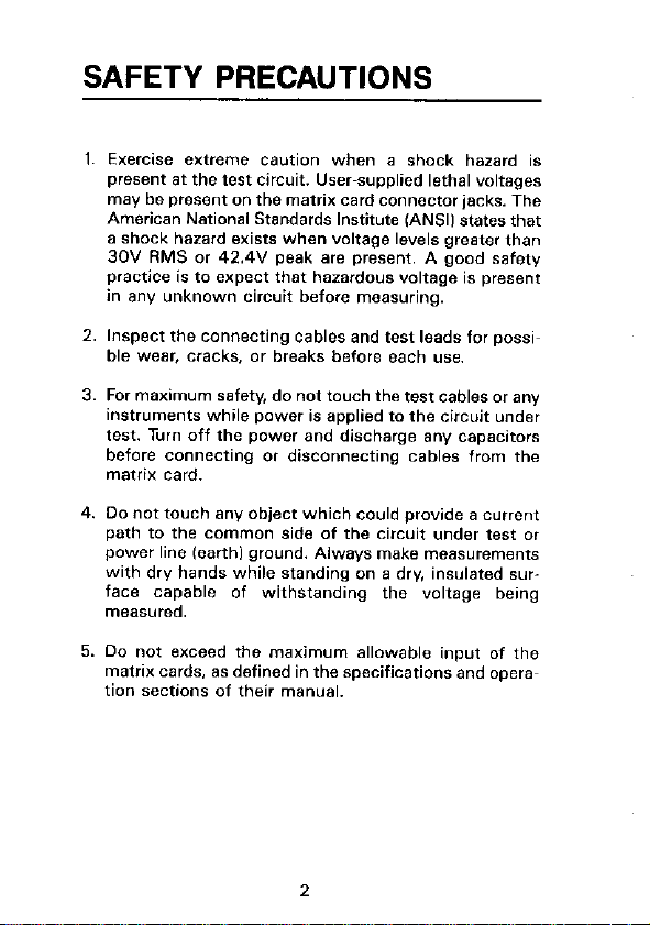
SAFETY PRECAUTIONS
2. Inspect the connecting cables and test leads for possi~
ble wear, cracks, or breaks before each use.
3. For maximum safety. do not touch the test cables or any
iktrumenfs while power is applied to the circuit under
test. Turn off the power and discharge any capacitors
before connecting or disconnecting cables from rhe
InmiX car*.
5. Da not exceed the maximum allowable input of the
matrix cards. as defined in the specifications and operas
tion sections of their manual.
2
Page 7
FRONT PANEL
FAMILIARIZATION
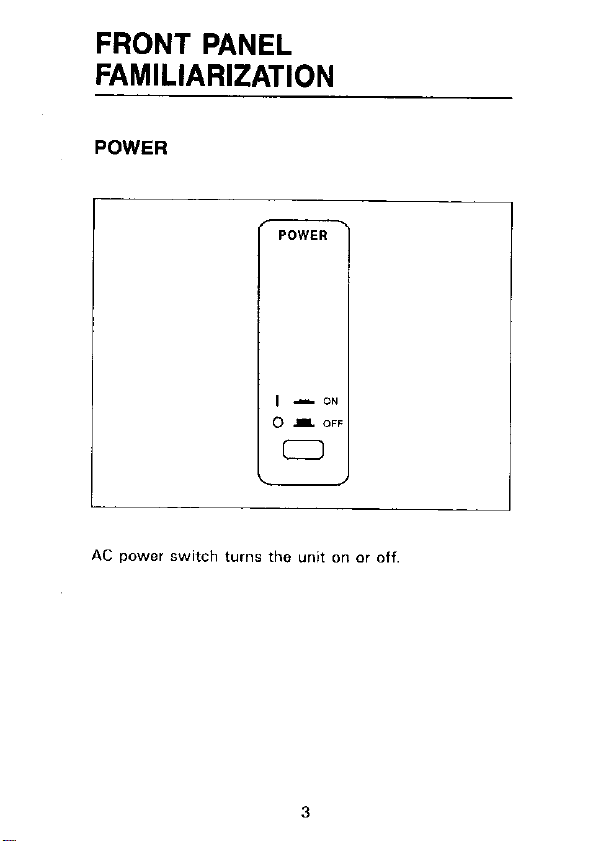
POWER
AC power switch turm the unit on or off,
3
Page 8
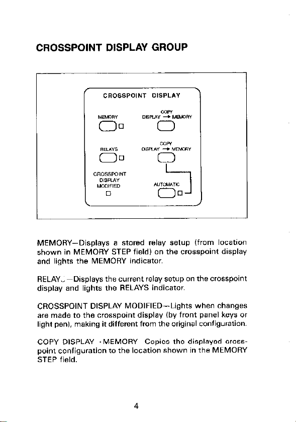
CROSSPOINT DISPLAY GROUP
MEMORY--Displays a stared relay setup (from location
shown in MEMORY STEP field) on the crosspoint display
and lights the MEMORY indicator.
RELAYl~Oisplays the current relay setup an the crosspoint
display and lights the RELAYS indicator.
CROSSPOINT DISPLAY MODIFIED-Lights when changes
are made to the crosspaint display (by front panel keys or
light pen), making if different from the original configuration.
COPY DISPLAY--MEMORY--Capies the displayed crosspoint configuration to the location shown in the MEMORY
STEP field.
4
Page 9
COPY DISPLAY-RELAYS-Copies the displayed crosspoint
configuration to the relays.
AUTOMATIC (COPY DISPLAY--RELAYS)-When this LED
is lit. any change to the crosspoint display is sent to the
relays at the same time. The pushbutton toggles the LED
on and off. ITo affect chanae in memarv, displav must be
copied to memory.~
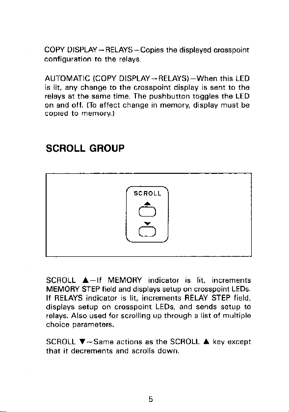
SCROLL GROUP
SCROLL A-If MEMORY indicator is lit, increments
MEMORY STEP field and displays setup on crosspoint LEDs.
If RELAYS indicator is lit. increments RELAY STEP field,
displays setup on crosspoint LEDs, and sends setup to
relays. Also used for scrolling up through a list of multiple
choice parameters.
SCROLL .-Same actions as the SCROLL A key except
that if decrements and SCrdS down.
Page 10
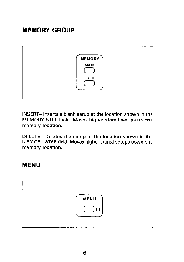
INSERT-Inserts a blank serup at the location shown in the
MEMORY STEP Field. Moves higher stored setups up one
memory location.
DELETE-Deletes the setup at the locafion shown in the
MEMORY STEP field. Moves higher stored setups down one
memory location.
MENU
r
MEN”
00
0
Page 11
I
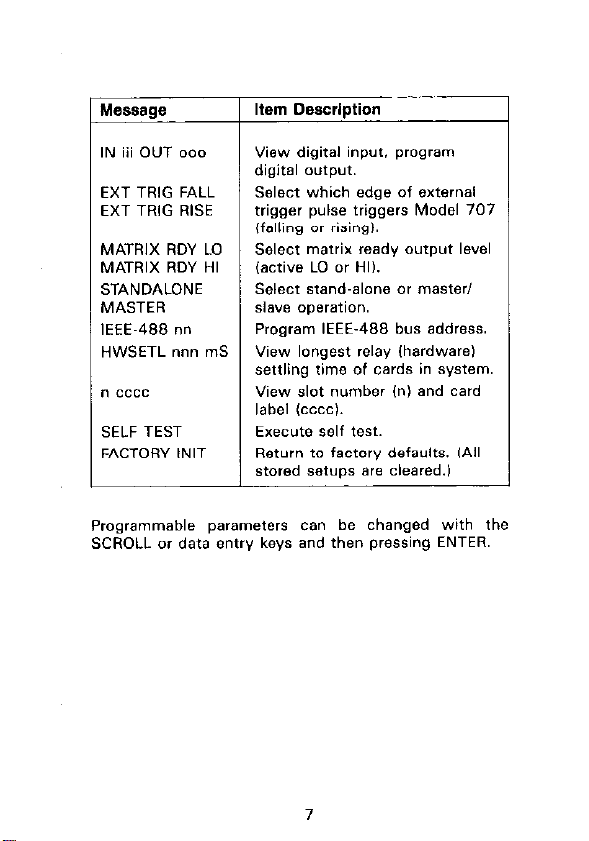
Message
I
Item Description
view digital input. program
digital output.
EXT TRIG FALL
EXT TRIG RISE
Select which edge of external
trigger pulse triggers Model 707
(falling or rising).
MATRIX RDY LO
MATRIX RDY HI
STANDALONE
MASTER
IEEE-488 nn
HWSETL nnn mS
Select matrix ready output level
(active LO or HI).
Select stand-alone OI master,
~l.we operation.
Program IEEE-488 bus address.
View longest relay Ihardware)
settling time of cards in system.
n cccc
View slot number Ini and card
label tcccc,.
SELF TEST
FACTORY NIT
EYeCUte Self test.
Return to factory defaults. ,All
stored SetUpS a,0 cleared.,
Programmable parameters can be changed with the
SCROLL or data entry keys and then pressing ENTER.
I
7
Page 12
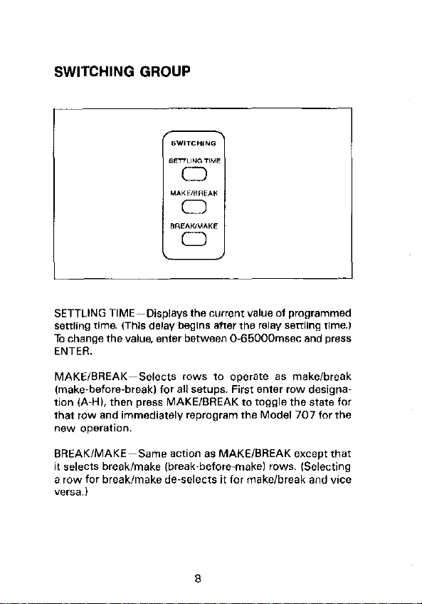
SETTLING TIME-Displays the current value of programmed
settling time. (This delay begins after the relay seftling time.1
To change the value. enter between 0.65000msec and press
ENTER.
MAKE/BREAK-Selects rows to operate as make/break
(make-before-break) for all setups. First enter row desigrw
fion IA-H), then press MAKE/BREAK fo roggle the state for
that row and immediately reprogram the Model 707 for the
new operation.
BREAK/MAKE-Same action 8s MAKE/BREAK except that
it selects break/make (break-before-make) rows. ISelecting
a row for break/make de-selects it for make/break and vice
versa.)
8
Page 13
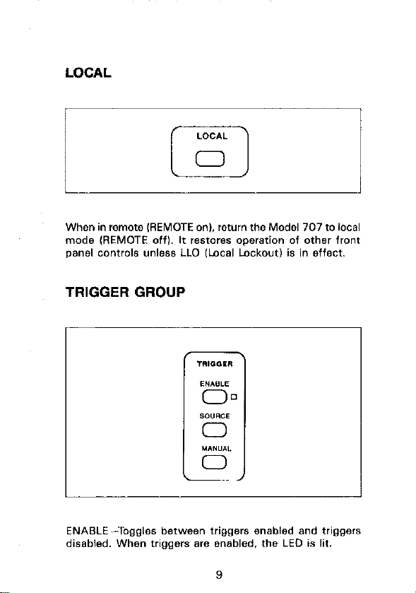
LOCAL
When in remote WEMOTE on). return the Model 707 to local
made (REMOTE off). If restores operation of other front
panel ~onfrols unless LLO llocal Lockout) is in effect
TRIGGER GROUP
ENABLE-Toggles between triggers enabled and triggers
disabled. When triggers are enabled. the LED is lit.
Page 14
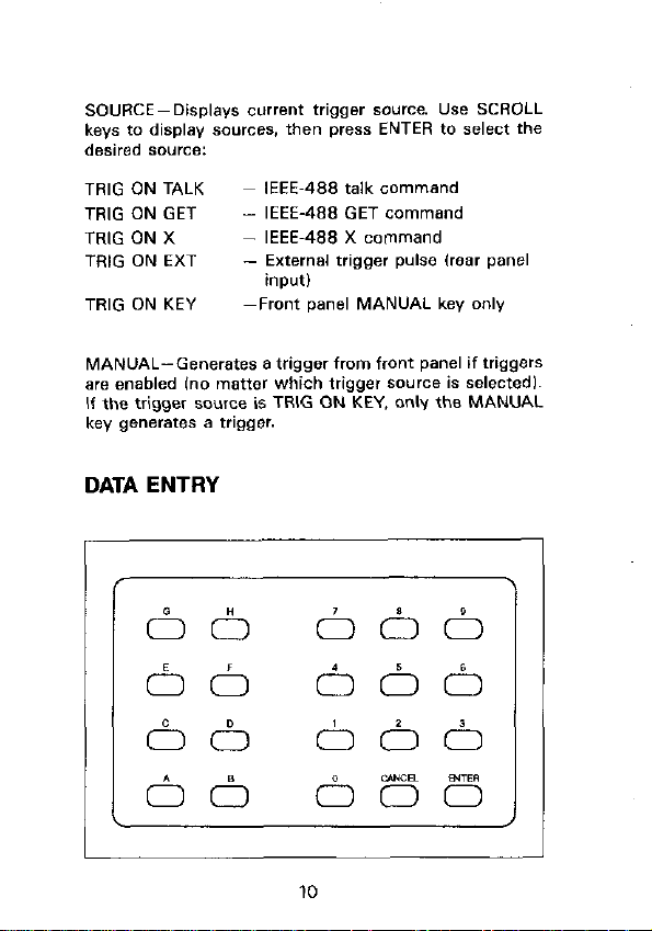
SOURCEPDisplays current trigger source. Use SCROLL
keys 20 display sources, then press ENTER to select the
desired source:
TRIG ON TALK
TRIG ON GET
TRIG ON X
TRlG ON EXT
TRIG ON KEY
MANUAL-Generates a trigger from front panel if triggers
are enabled (no matter which trigger source is selectedl.
If the trigger source is TRIG ON KEY. only the MANUAL
key generates a trigger
IEEE-488 talk command
- IEEE-488 GET command
- IEEE-488 X command
- External trigger pulse (rear panel
input)
-Front panel MANUAL key only
DATA ENTRY
Page 15
ASH, O-S-These keys are for entering row/column addresses
and setup locations, selecting make/break and break/make
rows, and entering various numeric values.
CANCEL-If the value in the alphanumeric display has been
modified, this key restores the currenf parameter value. If
the velue in the alphanumeric display has not been modified,
this key returns the Model 707 to the previous display.
CANCEL also exits from menu mode if no changes have
been made.
ENTER-If the value in the alphanumeric display has been
modified, pressing this key stores the parameter value. Also
invokes immediate action items from the menu and exits
menu mode (except when digital 110 is displaYedI
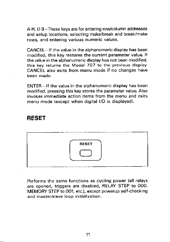
RESET
LI:
Performs the same functions as cycling power Call relays
are opened. triggers are disabled. RELAY STEP to 000,
MEMORY STEP fo 001, etc.). except powerup self-checking
and masterislave loop initieliration.
Page 16
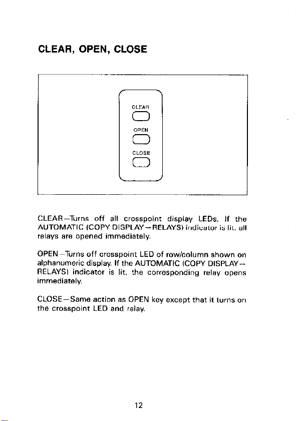
CLEAR, OPEN, CLOSE
CLEAR--Turns Off a,, crosspoint display LEO% If the
AUTOMATIC ICOPY DISPLAY--RELAYS) indicator is lip. all
relays are opened immediately.
OPEN -Turns off ~rcmpoint LED of row,column shown on
alphanumeric display. If the AUTOMATIC (COPY DISPLAYRELAYSI indicator is lit. the corresponding relay opens
immediately
CLOSE~Same action as OPEN key except that it turns on
the crosspoint LED and relay.
Page 17
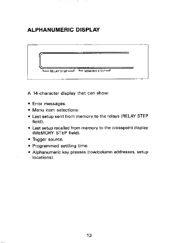
ALPHANUMERIC DISPLAY
pziizzs
A Wcharacter display that can show:
. Error messages.
l Menu item selections.
. Last setup sent from memory to the relays (RELAY STEP
field,.
Page 18
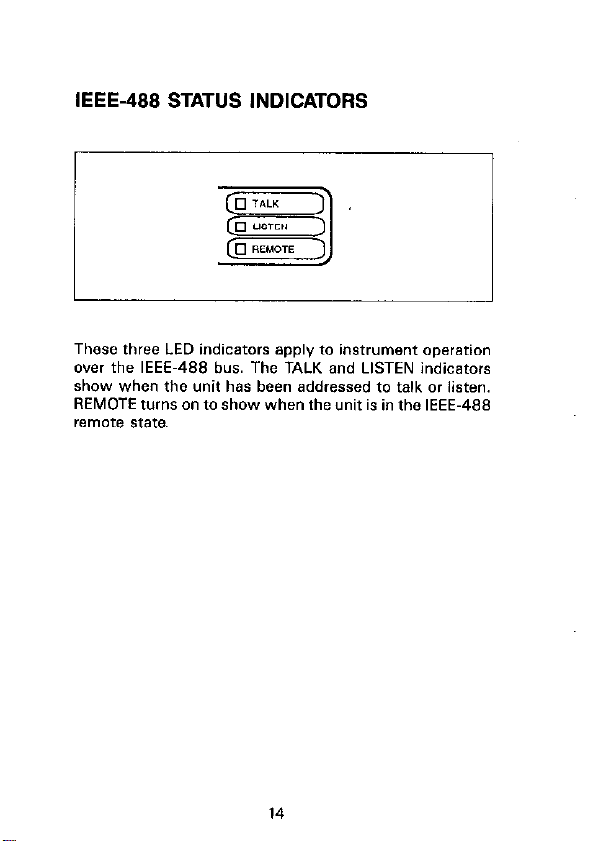
IEEE-488 STATUS INDICATORS
These three LED indicators apply to instrument operation
over the IEEE-488 bus. The TALK and LISTEN indicators
show when fhe unit has been addressed to talk or listen.
REMOTE turns on to show when the unit is in the IEEE-488
remote State.
Page 19
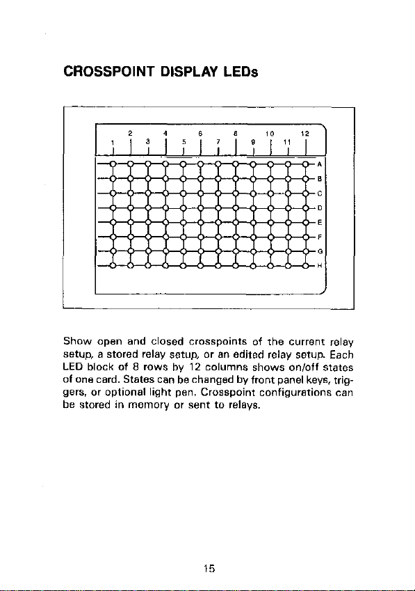
CROSSPOINT DISPLAY LEDs
Show open and closed crosspoinrs of the CUllem relay
setup, a stored relay setup, or an edited relay setup. Each
LED block of 8 rows by 12 columns shows on/off states
of one card. States can be changed by front panel keys. triggers. or optional light pen. Crosspoint configurations can
be stared in memory or sent to relays.
Page 20
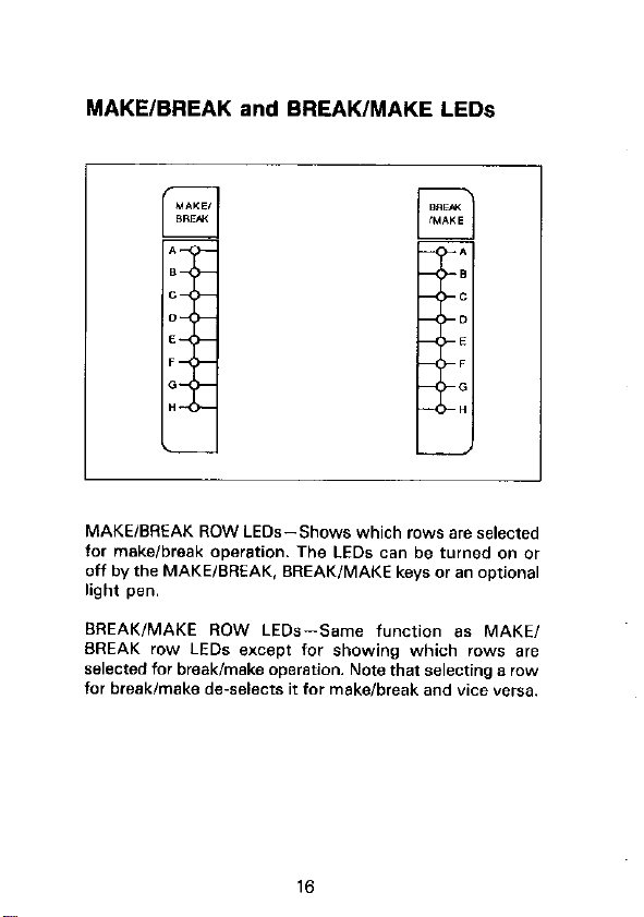
MAKE/BREAK and BREAK/MAKE LEDs
MAKE/BREAK ROW LEDs-Shows which rows are selected
for mskeelbreak operation. The LEDs can be turned on or
off by the MAKE/BREAK. BREAK/MAKE keys or an o,,tional
light pen.
BREAK/MAKE ROW LED*-Same function as MAKE,
BREAK row LEDs except for showing which rows are
selected for break/make operstion. Note thaf selecting a ,a.,
for break/make de-selects it for make/break and vice versa.
16
Page 21

LIGHT PEN
r
An optional input device for toggling the on/off state of the
Crosspoint Display LED*. MAKE/BREAK row LEDs. and
BREAK/MAKE row LEDs. One light pen is used to control
the LEDs of up to five Model 707 mainframes.
Page 22

DISPLAY MESSAGES
Table 1. Additional Messages
Message
CARD ID ERROR’
IDDC
IDDCO
,N”ALlD lNPtJT
M/S ERROR’
M,S LOOP DOWN
NOT IN REMOTE
Description
Checksum test failed on one
or more matrix cards.
Invalid device-dependent
command.
Invalid device-dependent command option.
Light pen button pressed wher
pen was not painted at WOSS~
point LED or make/break or
breakimake LED.
Error in master/slave communication loop foverrun. parity,
framing. count imbalance, or
time-out).
One or more units connected
in masrer,sla”e loop are “Of
powered u,,.
“x” character received over
IEEE-488 bus b”t Model 707
is not in remote.
Page 23

Table 1. Additional Messages (Cont.)
Descrfptlon
Additional trigger received
before programmed settling
time expired (trigger is
wocessed).
Self-test detected error in
RAM.
Self-test detected checksum
error in ROM.
SETUP ERROR’
TRIG OVERRUN
“Message remains displayed until next operation.
Self-test detected checksum
error in stared setup.
An additional trigger was
received before the Model 707
asem the READY signal.
Page 24

REAR PANEL FAMILIARIZATION
CARD SLOTS
The Model 707 accepts up fo six plug-in matrix cards 18
rows by 12 colurnns~ per mainframe
MASTER/SLAVE
MASTER/SLAVE OUT-An S-pin DIN connector for connecting a cable to the next mainframe in a master/slave daisy
chain configuration.
MASTER/SLAVE IN-An S-pin DIN connector for connecting a cable from the previous mainframe in a master/slave
daisy chain configuration.
20
Page 25

BNC JACKS
EXTERNAL TRIGGER INPUT-A BNCjack for applying a trip
ger pulse to change to the next relay setup. if triggers are
enabled and TRIG ON EXT is selected as the source. Pulses
must be TTL-compatible. negative- or positive-going
lselected by a menu item). with a duration greater than
600nsec.
MATRIX READY OUTPUT-A BNC jack providing a TTL-
compatible, high- or low-true level (selected by a menu item).
If goes false when relays are switched and goes true after
the sum of the relay settling time and the programmed setfling time.
Page 26

RELAY TEST
A G-pin quick-disconnect terminal block with logic ground
and four logic inputs for testing crosspoint relay closures.
Wiring between this terminal block and rows A and B of
any card in the group of cards to be tested is necessary for
the test. Test connections are detailed in the card rn~~~als.
DIGITAL I/O
r
L
A DB-25 connector for the TTL-compatible digital I/O with
data lines for eight inputs and eight outputs. It also con-
22
Page 27

rains control lines ‘0, handsnaking r,nput Latch ana cl”T~
put Strobe). Input lines are viewed and output lines are pro-
grammed through a menu item
IEEE-488 INTERFACE
This connector interfaces the Model 707 to the IEEE-488
bus. IEEE-488 interface function codes are marked adjacent to the connector.
23
Page 28

AC POWER
LINE VOLTAGE SELECTED-The position of this switch
determines the operating voltage range of the instrument:
$0.1lOV. 105.125v, or 180.22ov. 210.25ov.
AC RECEPTACLE-Power is applied through the supplied
power cord to the S-terminal AC receptscle.
LINE FUSE-The line fuse provides protection for the AC
power line input. The fuse rating mu% match the line voltage
semng.
24
Page 29

INSTALLING AND REMOVING
CARDS
Figure 1. installing a Card
Turn 0” matnfmme power and dkonneet the
he cord before Installing or removing cards.
WARNING
Page 30

DO not touch the card surfaces, con”ecton, or DO not touch the card surfaces, con”ecton, or
CAUTION CAUTION
components to avold contamlnatlo” that could components to avold contamlnatlo” that could
degrade card pertormance. degrade card pertormance.
1. Ensure that the access door on top of the mainframe is
fully closed and lacked down. (The bottom side of the
access door has card guides.1
2. Remove the slot cover from the desired slot.
3. With one hand grasping the card’s handle, and the other
supporting its weight. line up the card with the card
guides in the slot. Ensure that the component side is facing the fan of the mainframe.
4. Slide the card into the mainframe until it is fully seated
in the backplane connectors. Finger-tighten the springloaded mounting SCW.VS at the back of the card to lock
it in o,ace.
The mounting screws must be secured to ensuw
WARNING
a proper chassis gmund connection between the
card and the mainframe. Fallurn to property
secure this ground connectlo” may result in personal inJury or death due to electric shock.
5. To remove a matrix card. first turn off the mainframe and
disconnect the line cord. Ensure “a voltage is applied from
the u~er’~ circuit. Remove any infernal cabling between
cards through the unit’s accept door. Loose” the springloaded mounting screw and pull out the card by its
handle.
26
Page 31

MASTER/SLAVE SYSTEMS
A method of expanding a matrix with multiple mainframes
is tO connect up to five units in a masterlslsve configuration. This is done by connecting the rows of like cards in
separate units and by connecting the units in a closed loop
of OIN cables for communication and canfrof. A
masterislave system configuration appears as one unit with
expanded card capacity. That is. only the master unit is addressed by the IEEE-488 bus CO”~,O,,B, and controlled from
the front panel.
A mesterhlsve configuration extends matrix rows yielding
a long, narrow matrix. Figure 2 shows the connections between two units having Model 7071 cards. With five units.
the maximum matrix size is 8 rows by 360 columns. Table
2 shows the column assignments for the maXimm
configuration.
If the mainframes of a master/slave configuration contain
different card models, group like csrds 8s much as possi~
ble. This will reduce the need to extend the analog buses
with exfernsl cables.
27
Page 32

Flgure 2. Example of Master/Slave Interconnect Cables
28
D
Page 33

Table 2. Master/Slave Columns
unit
1
Master
2
Slave 1
3
save 2
4
Slave 3
5
Slave 4
Slot
1
2
3
4
5
6
1
2
3
4
5
6
1
z
4
5
6
1
:
4
:
1
2
3
4
5
6
Columns (l-12)
I-12
13.24
26-36
37-46
49-60
61~72
73-64
65-96
97-108
109-120
121-132
133-144
145-156
157-166
169-160
161-192
193-204
205-216
217-228
229-240
241-252
253-264
265-276
277-286
289-300
301-312
313~324
325-336
337-348
349-360
29
Page 34

BASIC SWITCHING OPERATION
The following paragraphs will take you through a simple,
general, step-by-step procedure to edit a matrix setup, store
it in memory. and send the setup to the relays. Althwgh
ihe steps are described with front panel operations. the procedure can be performed over the IEEE-488 bus.
Figure 3 shows the setup data paths for these steps.
Figure 3. Setup Data Transfers
30
Page 35

Selecting Make/Break and Break/Make ROWS
Select make-before-break, break-before-make. or don’t care
operation for the rows. The selections will be in effect for
alI relay switching. even if a stored setup is not used. IAs
a general rule, use makeibreak operation for current murces
and breakimake for voltage sources.,
“se the data entry keys to select a mw, then press
MAKE/BREAK or SREAK,MAKE fO toggle the state. lselec~
ting one state for a row de-selects it for th8 other.1 This
operation can also be performed with the light pen by using if to turn on/off the MAKWSREAK and SREAK,MAKt
LEDS.
Modifying a Relay Setup
Step 1: S&et a Stowd Setup
If you want to modify set”,, #I, just press the MEMORY
key. The MEMORY indicator light will light. To select another
setup fup fo location 1001. use the numeric data entry keys
(leading zeros are not necessaryl. then press the MEMORY
key.
Step 2: Modify the Displayed Setup
Use the data entry keys to select a crosspoint address IA1
fhrwgh H721. then press the OPEN or CLOSE key
Keystrokes will be shown an the alphanumeric display and
the CROSSPOINT DISPLAY MODIFIED indicator will light.
31
Page 36

If You have the optional light pen. toggle the state of a crosspoint LED by holding the light pen perpendicular to and
touching the front panel overlaY and pressing the light pen
button.
Continue editing with the front pane, key or light pen until
the ~ros~point display shows the desired configuration.
Storing Setup and Sending to Relays
Step 1: Storing Setup in Memory
To store the modified setup at the location shown in the
MEMORY STEP field, just press the COPY DISPLAYMEMORY KEY. This action wewrites the old setup data
at that location with the newly modified setup.
To select a different memory location, key in a valid local
tion number, then press the COPY DISPLAY-MEMORY key
The MEMORY STEP field is se, to the new location.
Step 2.4: Sending Setup to Relays
To make the newly modified setup the current relay setup,
just press the COPY DISPLAY-RELAYS key. The relay states
will be changed to reflect the modified setup data. If the
MEMORY LED is lit. the RELAY STEP field will be set equal
to the MEMORY STEP field. In effect. this copies a setup
from memory to the relays.
32
Page 37

Step 28: Triggering Setup to Relays
If you modified setup #I and restored it to memory at the
same location. a single trigger will copy the setup to the
relays. Do this by pressing the trigger SOURCE key. scrolls
ing to the “TRIG ON KEY” display and pressing ENTER.
Then press the trigger ENABLE key Pressing the trigger
MANUAL key will copy setup #I to the relays and set the
RELAY STEP field to 001.
33
Page 38

Page 39

IEEE-488 PROGRAMMING
DEVICE-DEPENDENT COMMANDS
Close crowpoint* of setup indicated by edit pointer frows A-H,
Dcccccccccccccc Display ASCII characters 114
35
Page 40

Edit Pointer
EO
E”
Enable/Disable Triggers
FO
FI
m
Point to CUrrent relay setup
Paint to stored relay setup 11-1001
Disable triggers
Enable triggers
1
Full output, all data
in one talk
1 G4
G5
G6
G7
._...
Condensed output, all data in one
talk
Condensed output. one mainframe per talk
Binary output, all data in one talk
Binary output, one mainframe per
talk
36
Page 41

Insert blank setup in memory
,l-1001
Self-test
JO Perform SewteSt
EOI and Hold-off
KO
Send EOI, hold-off on X until
Read”
K1
K2
K3
K4
No EOI. hald~off on X until Read”
Send EOI. do not hold-off on X
No EOI, do not hold-off on X
Send EOI. hold-off on X until
Matrix Ready
K6
No EOI, hold-off an X until Matrix
Read”
Download Setups
Lbbb...X Download setups from controller
to Model 707
SRQ
MO
MI
M2
M4
M6
Ml6
M32
Ml28
SRQ disabled
not used
Front pane, key press
Digital 110 interrupt
Matrix Ready
Ready for trigger
Error
not used
I
37
Page 42

/ Dfgftaf Output
0”“” Set states of digital output lines
1000-255~
Delete Setup
on
Delete setup from memory 11-100)
Restore Defaults
RO
Restore factor” defaults
Programmed Settling Time
S”
Program settling time in msec
10.65000,
38
Page 43

mgger
TO or T,
T2 or T3
T4 or T5
T6 0, T7
T6 o, Tg
Trigger on talk
Trigger on GET
Trigger on X
Trigger on External Trigger pulse
Trigger on front panel MANUAL
key only
status
“0
ut
“2.”
Send machine status word
Send error status word
Output setup “n” IO-1001 with
current G format
u3
u4
U5.U
Send RELAY STEP pointer
Send number of slaves
Send model number of each card
in unit “u” IO-41
U6
u7
Send relay settling time
Send digital input of unit
Send RELAY TEST input
Make/Break
“abcdefgh
Select rows for makeibreak opera-
tion (00000000 111111111
Break/Make
Wsbcdefgh Select rows for breaklmake opera-
tion ~00000000 11111111,
39
Page 44

Execute
x
EXeC”te commands
copy setup
ZO,”
Z”,O
Zm,n
copy current relay SefUp to
mamory location “n” (1.1001
copy SetUp frmn memOly location
“ll” w1001 to relays
Copy setup from location “m”
IO-1001 to location “n” 0100)
DATA FORMATS
When uploading setup data to the controller, the data will
be in one of the formats that follow. The example data
shown is for set”,, #3 of a stand-alone unit with crasspoints
Al. AZ, 919. 820. C27. C28. D37, D38, FL?,. and F62 being closed.
40
Page 45

GO and 01 Full Output
41
Page 46

62 and 03 inspect Output
64 and GS Condensed Output
42
Page 47

G6 and G7 Binary Output
43
Page 48

HIT KEY COMMANDS
Table 3 lists hit key commands sent over fhe IEEE~488 bus
to emulate front pane, key presses.
Table 3. Hit Keys
ammand Iby Command Key
44
Page 49

SRO MASK AND SERIAL POLL BYTE
Page 50

STATUS WORDS
UO Machine Status Word
Page 51

Ul Error Status Word
U3 Relay Step Pointer
47
Page 52

U4 Number of Slaves
/
48
Page 53

U5 Card Identifications
49
Page 54

U6 Relay Settling Time
U7 Digital Input
Page 55

U6 Relay Test Input
Page 56

PROGRAMS
IBM PC/XT/AT with Capital Equipment
Corporation PC< >466 Interface
(Kelthley PC-466~CEC)
The following program sends a command string from an
IBM PC/XT/AT computer to the Made, 707 and displays the
response an the CRT The computer must be equipped with
a CEC interface card and DOS 2.0 (or later revision)
opermng system.
DIRECTIONS
1. Using the front panel menu feature, set the primary
IEEE-488 address of the Model 707 to 18.
2. With the power off, connect the Model 707 to the
IEEE-488 interface card installed in the IBM computer.
3. Type in BASICA an the computer keyboard to get into
the IBM interpretive BASIC language.
4. Enter the lines below using the return key after each line.
5. Run the program and type in the desired command string
at the ENTER COMMAND STRING, ,,ram,,t. For example, $0 close crosspoint Al, type in CAIX and press the
return key. (The Model 707 software revision. e.g.
707A01. will then appear on the computer display for
device-dependent commands which have no response.)
If the command “G2U2,OX” is typed in at the prompt.
the response will be a display of the closed crosspoints
of the current relay setup.
52
Page 57

PROORAM
COMMENTS
Prompf for string
53
Page 58

IBM PC/XT/AT with Capital Equipment
Corporation PC < > 406 Interface and
ASYST Software
The ASYST program listed here sends a command string
from an IBM PC,XT,AT compufer to the Model 707 and
displays the response on the CRT. The computer must be
equipped with a CEC interface card and DOS 2.0 (or later
revisionI operating system.
The optional GPWEEE-488 software module for the ASYST
package is required. Hardware requirements for ASYST include: 640K RAM. math coprocessor. parallel port. and hard
drive IrecommendedL
DIRECTIONS
1. Using the front panel menu key, set the primary
IEEE-488 address of the Model 707 fo 18.
2. With the power off. connecf the Model 707 to the
IEEE-488 interface card installed in the IBM computer.
3. Boot ASYST software from DOS. You will get an OK
prompt.
4. Use the <F2> key to enter the Main Configuration
Menu. In addition to the usual configuration rep
quirements of ASYST, the GPl8 must be configured.
From the Overlay Configuration Menu. select overlays
GPIB Master snd TYpe 1 NEC GPl8 Driver.
From the GPIB Configuration Menu. select a bus
number. board type INational GPIB-PC1 or GPIB-PC21.
memory address f2881. primary address 101, and interrum line.
Page 59

5. Save your changes end return to the OK prompt.
8. Use the command line editor (EDIT 707.DMOI to enter
the following program. Save the program and exit the
editor.
7. When prompted. load the program with the L key, or
type LOAD 707.DMO from the OK prompf.
8. When the program loads properly, type MAIN from the
OK prompt to start execution.
8. Type in the desired command string at the “Enter corn-
mand string:” prompt. For example, to close crosspoinr
Al. type in CAlX snd press the refum key. (The Mode,
707 software revision. e.g. 707AOl. will then appear
an the computer dis.play for device-dependent commands which have no response.1
If the command “G2U2,OX” is typed in at the prompt,
the response will be a display of the closed crosspoints
of the current relay setup.
10. Type <Control-Break> to exit the program loop of
707.DMO and return to the OK prompt. The programdefined words can be removed from the ASYST dictionary by typing FORGET 707.
PROGRAM
BWINIT
SEND.INTERFACE.CLEAR
REMOTE.ENABLE.ON
SYNCHRONO”S.GP,B
?GPIE.DEVICES
18 GPIBDEVICE 707
COMMENTS
\ Initialize bus
\ Take control of bus
\ Allow remote operation
\ Mske sure ASYST is in
sync. mode
\ List controller
parameters
\ Set 707 address and
name
Page 60

EOI.ON
EOS.ON
\ Enable end or identify
\ Enable end of string
10 EOS.CHARACTER
1000 TIMEOUT
,GPIB.DE”ICE
100 STRING COMMAND
100 STRING RESPONSE
: GET.INP”T
CR .” Enter command
*tring: ”
“INPUT COMMAND “:=
: MAIN
BEGIN
ME
GET.INPUT
707
COMMAND GPIB.WRlTE
RESPONSE GPIB.READ
CR RESPONSE “TYPE
AGAIN
\ Use LF terminator
\ Set timeout of kc
\ List 707 parameters
, Allacate 100 bytes for
“SW Input
\ Allocate 100 bytes for
707 reSpO”*e
\ Get DOCs
\ Definition for main
program
\ start loop
\ Make controller current
device
\ Get DOCs from user
\ Make 707 current
device
\ Send DDCs to 707
\ Get response
\ Display response
\ Return for more
CO”TlW”dS
Page 61

Hewlett-Packard Model 9000 Series ZOO/300
The following progrsm sends a command string to the
Model 707 from B Hewlett-Packard Model 9000 Series
200/300 computer and displays the response on the com-
puter CRT. The computer must be equipped with HP BASIC
4.0.
DIRECTIONS
1. Using the front panel menu feature. set the primary
IEEE-498 address of the Model 707 to 18.
2. With the power off. connect the Model 707 to the
IEEE~4BB interface card installed in the HP computer.
3. Enter the lines in the program below, using the
ENTER/RETURN key after each line.
4. Press the RUN key and type in the desired command
string at the COMMAND STRING prompt. For example.
to close crosspoint Al, type in CAlX and press the
ENTER/RETURN key. (The Model 707 ~offware revision.
e.g. 707A01, will then appear an the computer display
for device-dependent commands which have no
response.,
If the command “GZU2,OX” is Typed in at the prompt.
the response will be 8 display of the closed crosspoints
of the current relay setup.
Page 62

Page 63

Page 64

-
Tat Instrumentation Group
28775 Aurora bad / Clewland, Ohio 44139
-
 Loading...