

Page 1

Model 7063 RF Switch Card
Instruction Manual
Contains Operating and Servicing Information
Document Number: 7063-901-01 Rev. A
Page 2

WARRANTY
Keithley Instmmcnts, Inc. warrants this product to bc free from defects in material and
workmanship for a period of 1 year from date of shipment.
Keithley Instruments, Inc. warrants the following items for 90 days from the dale of
shipment: probes, cables, rechargeable batteries, diskettes, and documentation.
During the warranty period, we will, at our option, either repair or replace any product
that proves to be defectivc.
To exercise this warranty. write or call your local Keithley representative. or contact
Keithley headquarters in Cleveland, Ohio. You will be given prompt assistance and
return instructions. Send the product, transportation prepaid, to the indicated service
facility. Repairs will be made and the product returned, transportation prepaid. Repaired
or replaced products are warranted for the balance of the original warranty period, or at
least 90 days.
LIMITATION OF WARRANTY
This warranty does not apply to defects resulting from product modification without
Keithley’s express written consent, or misuse of any product or part. This warranty also
doer not apply to fuses, software, non-rechargeable batteries, damage from battery leakage, or problems arising from normal wear or failure to follow instructions.
THIS WARRANTY IS IN LIEU OF ALL OTHER WARRANTIES, EXPRESSED OR
IMPLIED, INCLUDING ANY IMPLIED WARRANTY OF MERCHANTABILITY
OR FITNESS FOR A PARTICULAR USE. THE REMEDIES PROVIDED HEREIN
ARE BUYER’S SOLE AND EXCLUSIVE REMEDIES.
NEITHER KEITHLEY INSTRUMENTS, INC. NOR ANY OF ITS EMPLOYEES
SHALL BE LIABLE FOR ANY DIRECT, INDIRECT, SPECIAL, INCIDENTAL OR
CONSEQUENTIAL DAMAGES ARISING OUT OF THE USE OF ITS INSTRUMENTS AND SOFTWARE EVEN IF KEITHLEY INSTRUMENTS, INC., HAS
BEEN ADVISED IN ADVANCE OF THE POSSIBILITY OF SUCH DAMAGES.
SUCH EXCLUDED DAMAGES SHALL INCLUDE, BUT ARE NOT LIMITED TO:
COSTS OF REMOVAL AND INSTALLATION, LOSSES SUSTAINED AS THE
RESULT OF INJURY TO ANY PERSON, OR DAMAGE TO PROPERTY.
Page 3
Model 7063 RF Switch Card
Instruction Manual
Page 4

Safety Precautions
The following safety precautions should be observed before using this product and any associated insrmmentation. Although some instmments and accessories would normally be used
with non-hazardous voltages, there are situations where hazardous conditions may be present.
This product is intended for use by qualified personnel who recognize shock hazards and are
familiar with the safety precautions required to avoid possible injury. Read the operating ins
formation carefully before using the product.
The types of product users are:
Responsible body is the individual or group responsible for the use and maintenance of
equipment, for ensuring that the equipment is operaled within its specifications and operating limits, and for ensuring that operators are adequately trained.
Operators use the product for its intended function. They must be trained in electrical safety
procedures and proper use of the insmnncnt. They must be protected from electric shock and
contact with hazardous live circuits.
Maintenance personnel perform routine procedures on the product to keep it operating. for
example, setting the line voltage or replacing consumable materials. Maintenance procedures
are described in the manual. The procedures explicitly state if the operator may perform them.
Otherwise, they should be performed only by service personnel.
Service personnet are trained to work on live circuits, and perform safe installations and repairs of products. Only properly trained sewice personnel may perform installation and ser.
vice procedures.
Exercise extreme caution when a shock hazard is present. Lethal voltage may be present on
cable connector jacks or test fixtures. The American NationaJ Standards Institute (ANSI)
states that a shock hazard exists when voltage levels greater than 30” RMS, 42.0 peak, or
60VDC are present. A good safety practice is to expect that hazardous voltage is present
in any unknown circuit before measuring.
Users of this product must be protected from electric shock at all times. The responsible body
must ensure that WWF are prevented access and/or insulated from every connection point. In some
cases, connections must be exposed to potential human contact. Product users in these circumstances must be trained to protect themselves from the risk of elecnic shock. If the circuit is capable of operating at or above 1wO volts, no conductive part of the circuit may be exposed.
As described in the lntemational Electrotechnical Commission (IEC) Standard IEC 664, digital multimeter measuring circuits (e.g., Keitbley Models 175A, 199. 2000, 2001. 2002, and
2010) are installation Category II. All other instruments’ signal terminals are Installation Category 1 and must not be connected to mains.
Do not connect switching cards directly to unlimited power circuits. ‘Ibey are intended to be
used with impedance limited sources. NEVER connect switching cards directly to AC mains.
When connecting sources to switching cards, install protective devices to limit fault current
and voltage to the card.
Before operating an instrument, make sure the line cord is connected to a properly grounded
power receptacle. Inspect the connecting cables, test leads, and jumpers for possible wear,
cracks, or breaks before each we.
For maximum safety, do not touch the product, test cables. or any alher insbunents while power is applied to the circuit under test. ALWAYS remove power from the entire test system and
discharge any capacitors before: connecting or disconnecting cables or jumpers, installing or
Page 5

removing switching cards, or making internal changes, such as installing or removingjumpers.
Do not touch any object that could provide a current path to the common side of the circuit
under test or power line (earth) ground. Always make measurements with dry hands while
standing on a dry, insulated surface capable of withstanding the voltage being measured.
The instrument and accessories most be used in accordance with its specifications and operating instructions or the safety of the equipment may be impaired.
Do not exceed the maximum signal levels of the insuuments and accessoties. as defined in
the specifications and operating information. and as shown on the instrument or test fixture
panels, or switching card.
When fuses arc used in a product. replace with same type and rating for continued protection
against fire hazard.
Chassis connections most only be used as shield connections for measuring circuits, NOT as
safety earth ground connections.
If you are using a test fixture, keep the lid closed while power is applied to the device under
test. Safe operation requires the use of a lid interlock.
1fa @
tic user documenmtion.
The/& y bl
structions located in the manual.
The A
cluding the combined effect of normal and common mode voltages. Use standard safety precautions to avoid personal contact with these voltages.
The WARNING heading in a manual explains dangers that might result in personal injury or
death. Always read the associated information very carefully before performing the indicated
procedure.
The CAUTION heading in a manual explains hazards that could damage the instrumem.
Such damage may invalidate the warranty.
instrumentation and accessories shall not be connected to humans.
Before performing any maintenance, disconnect the line cord and all test cables.
To maintain protection from electric shock and fire, replacement components in mains cir-
cuits, including the power uansfomxr, test leads, and input jacks, most be purchased from
Keithley Instruments. Standard fuses, with applicable national safety approvals, may be used
if the rating and type are the same. Other components that are not safety related may be purchased from other suppliers as long as they are equivalent to the original component. (Note
that selected parts should be purchased only through Keithley Insnuments to maintain accoracy and functionality of the product.) If you are unstxe about the applicability of a replacement component, call a Keithley lnsouments office for information.
To clean an instrument, use a damp cloth or mild, water based cleaner. Clean the exterior
of the instrument only. Do not apply cleaner directly to the insounent or allow liquids to
enter or spill on the instrument. Products that consist of a circuit board with no case 01 chassis (e.g., data acquisition board for installation into a computer) should never require cleaning if handled according to instructions. If the board becomes contaminated and operation
is affected, the board should be returned to the factory for proper cleaning/servicing.
scow is present, connect it to safety earth ground using !he wire recommended in
s m o on an insb’ument indicates that the user should refer to the operating in-
symbol on an instmmcnt shows that it can sowce or measure loo0 volts or more, in-
RC”. 2m
Page 6
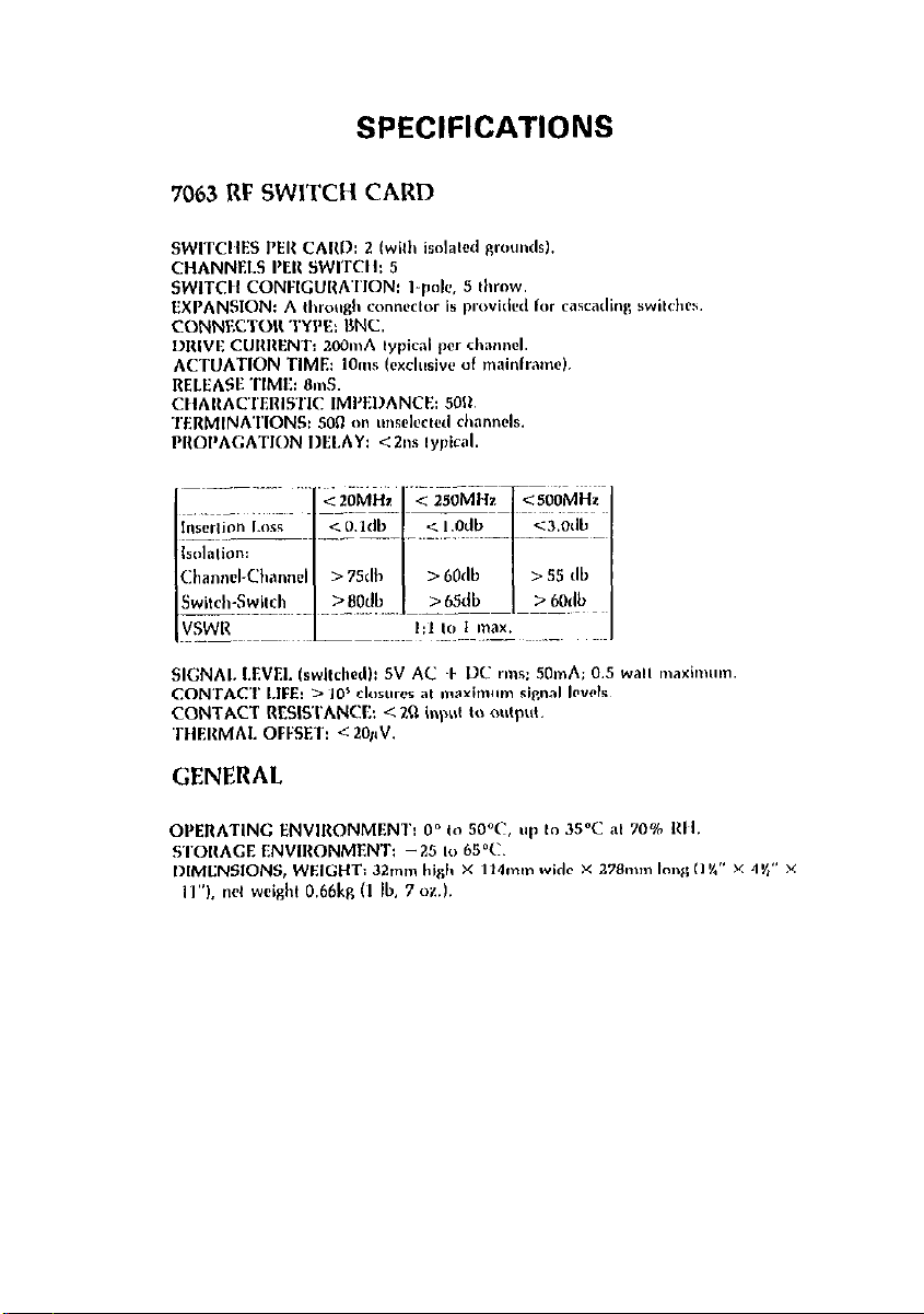
SPECIFICATIONS
<sOOMHz
a&lb
Page 7
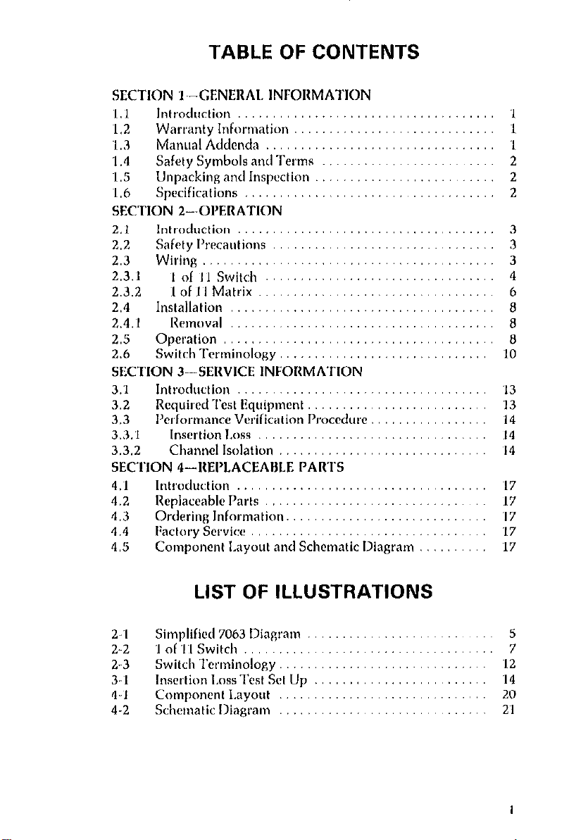
TABLE OF CONTENTS
‘I3
13
14
I4
‘14
4.1
4.2
4.3
4.4
4.5
2.‘1
2..2
2-3
3-I
4-l
4-2
LIST OF ILLUSTRATIONS
I
Page 8

LIST OF TABLES
2-l Cunnector/Mainframe Display llelationship. .......... 0
2-2 Model 706 Connector/Channel Assignment ......... 11
2-3 Model 705 Connector/Channel Assignment .... ..... I2
3-t Recommended Test Equipment .............. ...... 13
4 I Model 7063 lleplaccable Parts .. ............ ...... Itl
tt
Page 9
SECTION 1
GENERAL INFORMATION
1.1 INTRODUCTION
The Model 7063 is an RF scanner card that switches RF signals (up to
500MHz) from one channel to another. All channels switched are
terminated into 5011 when not selected. When a channel is closed, the
RF signal is routed from the input to the output. The Model 7063
works in conjunction with a scanner mainframe such as the Keithley
Model 705 or Model 706.
The Model 7063 incorporates two 1 X 5, switches on each card.
Each switch has a separate common (ground). This allows two
signals to be switched at the same time. One 1 X 5 switch could be
cascaded with the other 1 X 5 switch (on the same card) for a 1 X 10
switch configuration. Thus, the Model 7063 is configurable for
several different switch configurations.
Specified relay life is greater than 100,ooO closures. Cables are routed
from the rear of the card. The front plugs into the mainframe (e.g.
Model 705 or Model 706). The mainframe must be in the matrix
mode or 2-pole mode to operate the channels on the Model 7063
card. BNC connectors allow easy connections to input/output signal
paths.
1.2 WARRANTY INFORMATION
Warranty information is stated on the inside front cover of this
manual. If there is a need for service, contact the Keithley represen-
tative or authorized repair facility in your area. Check the back
cover for addresses. The service form supplied at the end of the
manual should be used to provide the service facility with adequate
information concerning any difficulty.
1.3 MANUAL ADDENDA
Improvements or changes to this manual will be explained on an addendum included with the manual. It is recommended that this information be incorporated immediately into the appropriate places in
the manual.
1
Page 10

If an additional instruction manual is required. order the manual
package (Keithicy Part Number 7063-901-00). The manual package
includes an instruction manual and all pertinent addenda.
1.4 SAFETY SYMBOLS AND TERMS
The symbol
instructions.
The symbol
terminal(s).
The WARNING used in this manual explains dangers that could
result in personal injury or death.
The CAUTION used in this manual explains hazards that could
damage the instrument.
denotes that the user should refer to the operating
A
denotes that a high voltage may be present on the
/v’
1.5 UNPACKING AND INSPECTION
The Model 7063 is inspected both electrically and mechanically
before shipment. Upon receiving the Model 7063, unpack all itmes
from the shipping container and check for any obvious damage that
may have occurred during transit. Report any damage to the shipping agent. Retain and use the original packaging materials in case
reshipment is necessary. The following items are shipped with every
Model 7063:
Model 7063 Scanner Card
Model 7063 instruction Manual
1.6 SPECIFICATIONS
For detailed specifications, refer to the specifications that precede this
section.
2
Page 11

SECTION 2
OPERATION
2.1 INTRODUCTION
This section provides the information necessary to use the Model
7063 with an appropriate Keithtey scanner mainframe such as the
Model 705 or Model 706. Once the card is configured and placed in
the appropriate slot in the scanner mainframe, refer to the scanner
mainframe’s instruction manual for complete operating details. This
section is divided into five parts: Safety Precautions, Wiring, Installation, Operation and Switch Terminology.
2.2 SAFETY PRECAUTIONS
1. Make sure the scanner mainframe is grounded through a properly
earth grounded receptacle before operation.
2. Inspect all test lead connections for wear and defects such as
cracks, exposed wires, (etc). Correct any defect found before
operating the scanner card with the mainframe.
3. Do not exceed the Model 7063’s maximum allowable signal level
as defined in the specifications.
4. Turn off all power supplies and discharge any residual power
before installing or removing the Model 7063 from the scanner
mainframe.
5. Turn off all power supplies and discharge any residual power
before installing or removing any wires from the Model 7063.
2.3 WIRING
Each channel on the Model 7063 consists of two siogle pole. Form C
relays and a 5011 terminating resistor. The 5On terminating resistor
consists of two lOOn resistors in parallel. Having two resistors in
parallel reduces the overall inductance of the resistors at higher frequencies. Input/output connections should be made using a high
quality 5Ofl coaxial cable with a standard mate RNC connector on
the Model 7063 end. Wiring diagram nomenclature is contained on
schematic diagram 7063.106 located at the end of this manual.
Cables are routed to the rear of the card, while the front plugs into
the scanner mainframe (e.g. Model 705 or Model 706). The mainframe must be in the matrix mode or the Z-pole mode to operate the
3
Page 12

channcts on the Model 7063 card. Refer to Tables 2-I and 2-2. To
configure a card for operation. it must have a minimum of two connections. ‘These two connections are listed as follows:
I. Input
2. output
In general:
1. The input is the signal path that is switch to one of several points.
The selected output is the path (channel) to which the input is
switched.
2. The output is the selection of one of several sources. Any of seven
inputs selected can be routed to the output for measurement or
processing. The 1 X 5 switch has six inputs which consist of five
channel selects and a through connection. The through connector
may be left open or connected to a source or terminator.
NOTE
Keep in mind that when a channel is open it is terminated
through 500 to ground.
2.3.1 1 x 5 Switch
With a 1 X 5 switch, the Model 7063 can switch one signal to any
one of five signal paths. Also, any one of five channels can be
switched to one signal path. Using the through connection as a sixth
channel (1 of 6) any one of six inputs can switch to one output. Also,
one input can be switched to any of six outputs. For example: Switch
1 OUT/IN can switch a signal to channels
l-l, 2-1, 3-1, 4-l
and
5-l.
Also, channels l-l, 2-1, 3-l. 4-l or 5-l can switch to SWITCH
OUT/IN. Only one channel will switch at a time on a 1 X 5 switch.
The Model 7063 incorporates two
1 X 5
switches so that two signals
can be switch at the same time. Each of the 1 X 5 switches incorporates a separate common (ground). For example: SWITCH
OUT/IN can switch a signal to channels
l-l, 2-1, 3-1, 4-1 or 5-l;
while SWITCH 2 OUT/IN switches another signal to channels 1-2,
2-2, 3-2, 4-2 or 5-2. Refer to Figure 2-1.
The advantage of using the 1 X 5 switch is that one channel will ac-
cess any one of five outputs. Also, one of five channels will access
one output. There are two separate 1 X 5 switches on each Model
7063. This allows two separate signals to be switched simultaneously.
4
1
1
Page 13

/OUT CHb2 CH4-2 CH3-2 CH2-2
Figure 2-l. Slmpllfled 7063 Diagram
6
Page 14

To operate the channels (open or close) once they arc configured,
plug the scanner card into the scanner mainhme and consult the
scanner mainframe’s instruction manual for complete details.
CAUTION
Do not exceed the voltage and frequency apecificstions of the Model 7063 scanner card. Instrument
damage may occur.
2.3.2 1 of 11 Switch
The Model 7063 can be configured as a 1 of 11 switch. To configure
the I of
nected to SWITCH 2 OUT/IN (I1007 connected to
11
switch, SWITCH 1 THROUGH IN/OLJT must be con-
J1008).
Another
possible I of ~1~1 switch is SWITCH 2 THROUGH IN/OUT connected to SWITCH 1 OUT/IN (J’lo14 connected to
JlOOl).
In either
of these configurations one channel can be switch to any one of 11
signal paths. Also. any one of 11 channels can be switched to one
signal path. For example; SWITCH 1 OUT/IN will switch toany one
of the following channels:
1. CH~l-1
2. CH2-1
3. CH3-.I
4. CH4-1
5. CHW
6. W-2
7. CHZ-2
8. CH3-2
9. CH4-2
10. CH5-2
11. CHb-2
Refer to Tables 2-l and 2-2. Refer to schematic diagram 7063-106 at
the end of this manual.
In another example, if SWITCH 1 OUT/IN is connected to SWITCH
2 THROUGH IN/OUT
(JlOOl
connected to J1014), then SWITCH 2
OUT/IN will switch to any one of the following channels:
6
Page 15

1,. CHl-1
2. CH2-1
3. CH3-1
4. CH4-I
5. CH5-1
6. CH6-1
7. w-2
8. CHZ-2
9. CH3-2
10. CH4-2
11. CH5-2
The advantage of cascading the two 1 X 5 switches is that one channel can access any one of 11 channels instead of one of five channels.
Refer to Pigure 2-2.
To operate the channels (open or close) once they are configured,
plug the Model 7063 into the scanner mainframe and consult the
mainframe’s instruction manual for details. The mainframe must be
in the matrix mode or the 2-pole mode to operate the channels on the
Model 7063 card.
CH 6.2
1
,,
CH 6-l
CH 6-Z CH 4-2 CH 3-2 CH 2-2
T
MODEL 7063
1 1 1
CH 6-l CH
4~1 CH 3-l CH 2-1 CH 1~1
I 1
Figure 2-2. 1 of 11 Switch
CH 1~2
SWITCH 2
OUTllN
4
SWITCH 1
OUT/IN
7
Page 16

2.4 INSTALLATION
WARNING
Turn off the mainframe end disconnect all other
equipment from the acenner card before installing/removing the card.
before installing the Model 7063 into the scanner mainframe, it must
be wired with the desired configuration. Refer to paragraph 2.3.
Once the card is configured, install it into the scanner mainframe.
Plug the scanner card into the appropriate slot in the rear panel of the
mainframe. In some mainframes, the scanner card is placed horizon-
tally into the unit. The cards are labeled top or bottom. In other
mainframes, the scanner cards are placed vertically in the unit and
numbered l-10. The scanner card is placed in the mainframe with the
card edge first. Align the card with the grooves in the slot and insert
the card to its full depth into the mainframe. Make sure the card is
properly seated into the connector in the mainframe. When the card
is fully inserted, the locking tabs should be pushed forward to the
center of the card to lock it in the mainframe.
NOTE
Refer to the scanner mainframe’s instruction manual for
complete details.
2.4.1
Removal
To remove a scanner card, first turn off the mainframe and all other
equipment connected to the card. Unfasten the locking tabs on the
card by pulling the tab outward. Grasp the end of the card and
carefully pull it out of the mainframe.
2.6 OPERATION
Model 7063 operation consists of two parts:
1.
Wiring the Model 7063 for the desired configuration
2. Mainframe control of the channels.
Refer to paragraph 2.3 for wiring information. Refer to the scanner
mainframe for information concerning the control of the channels.
Page 17

Refer to Table 2-l for Model 7063 connector/mainframe relation-
ship. The scanner mainframe must be in the matrix mode (Program
6. pole 0) or the Z-pole mode (Program 6. pole 2) to operate the channels of the Model 7063 card.
Table 2-1. Connector/Mainframe Display Relationship
-_
7083
cnnector
Matrix Mode
‘Mainframe Display
706
706
2-Pole Mode
tMainframe Display
706 706
J1002
J1003
J1004
J1005
J1006
J1007
J1009
JlOlO
JlOll
J1012
J1013
J1014
*Mainframe must be in the matrix rnt
001 1
002 1
003 1
004 1
005 1
xx
001 2
002 2
003 2
004 2
006 2
l **
01 1
02 1
03 1
04 1
05 1
xx
01 2
02 2
03 2
04 2
052
l o*
001 01
002 02
003 03
004 04
005 05
t”
006 06
007 07
006 06
009 09
010 10
et*
3 (Program 6, pole 0).
3dt
Use with separate 1 x 6 switches.
““Channel 13.? !s normal!y c!osecj.
“**Channel 6-2 is normally closed.
tMeinframe must be in the 2.pole mode (Program 8, pole 2).
Use when the card is connected a8 a 1 x 10 or larger awitcn.
.*
““*
The preceding connector/channel assignment is for slot 1 of the
Model 706 and top card slot of the Model 705. More channels are
available when connecting several Model 7063 cards and several
mainframes together. The Model 705 has two card slots. This meam
that for every Model 706 a matrix of 1 of 21 could be constructed.
With a maximum of five Model 70% daisy chained, a switch of 1 of
101 could be constructed.
9
Page 18

NOTE
The frequency response for the larger switching schemes
is not as good as a single 1 X 5 switch.
The Model 706 has 10 card slots. This means that for every Model
706 a switch of 1 of 101 could be constructed. With a maximum of
five Model 706s daisy chained, a switch of ‘I of 100’1 could be constructed.
NOTE
Refer to the mainframe’s instruction manual for informa
tion concerning daisy chain operation.
To construct such a large switching scheme, 50 Model 7063 cards
and five Model 706 mainframes are required. Connections between
the cards and mainframes is accomplished using the following for-
mat.
Connect card 1, CH6-I to SWITCH 2. To connect one card to
another, connect card 1, CH6-2 to card 2, SWITCH 1. The rest of the
cards are wired in the same manner. The connector/channel assignment for the larger configurations are described in Tables 2-2 and
2-3.
2.6 SWITCH TERMINOLOGY
Throughout this manual the terminology Form C is used. The term
Form C is used in switch terminology and is described as follows:
1. Form A is a single pole normally open (SPNO) switch. Refer to
Figure 2-3. Example: A 2-pole switch normally open is classified as
a 2 Form A.
2. Form B is similar to Form A except that its contacts are normally
closed. Refer to Figure 2-3. Example: A 2-p& switch that is normally closed is classified as a 2 Form B.
3. Form C is shown in Vigurc 2-3 as a single pole double throw
switch. It could also bc a multiple switch such as a 2-p& This
would be classified as a 2 f:orm C.
10
Page 19

Table 2-2. Model 706 Connector/Channel Assignment
:ard ,
1
2
3
4
5
6
7
8
9
10
1
2
3
Master
001-005
006..010
011-015
016-020
021.025
026.030
031~035
036.040
041.045
046.050
*Mac
Slave H
051.055
056-060
061-065
066.070
071-075
076.080
081-085
086.090
091-095
096.100
**2-P
tri
x Mode
Slave 12
101-105
106.110
111-115
116.120
121-125
126.130
131-136
136.140
141-145
146.150
ol
aMode
201-210
211-220
221-230
~__
I ;klve 13
161-166
156.160
161-165
166.170
171-175
176.180
181-185
186.190
W-195
196.200
301.310 401.410
311-320 411.420
321-330 421.430
Slave Xl
201-205
206-210
211-215
216-220
221-225
226.230
231-235
236.240
241.245
246.260
-1
4
5
6
7
8
9
10
"For each of the connector/channel assignments there am two
channels. These are the -1 and the -2 channels. Refer to the
schematic diagram 7062-106. Also, the matrix mode must be used
when using separate 1 x 5 switches.
*'The Z-pole mode must be used when the card is connected as a
1 x 10 or larger switch.
231-240
241.250
251.260
261.270
271-280
281-290
291-300
331-340
341-350
351-360
361-370
371.380 U-480
381-390 481-490
391-400 491-600
431.440
441.460
W-460
461.470
11
Page 20

Table 2-3. Model 706 Connector/Channel Assignment
Matrlx Mode
Card I Master Slave It Slave #2 Slave 13 Slave 14
Top 01-05
~J!!!orn 1 06-10 1 16-20 1 26-30 1 36-40 ( 46-50
Top
Bottom 11.20
‘For each of the connector/channel assignments there era two
channels. These are the - 1 and the -2 channels. Refer to the
schematic diagram 7062-106. Also, the matrix mode must be used
when using separate 1 x 5 switches.
l
*2-pole mode must be used when using connected 1 x 10 or larger
switches.
01.10
11-15 21-25
2-Pole Mode
21-30 41-50
31-40 51-60 71.80 91.100
31.35 41-45
61-70 81-90
12
Figure 2-3. Switch Termlnology
Page 21

SECTION 3
SERVICING INFORMATION
3.1 INTRODUCTION
This section contains a performance verification procedure. Since
there are no calibration adjustments, calibration is not necessary.
Recommended maintenance includes inspection of the scanner card
and the card edge connector to ensure good electrical contact. The
verification procedure should be performed upon receipt of the scanner card or at the time maintenance is performed on the card.
3.2 REQUIRED TEST EQUIPMENT
Recommended test equipment for performance verification is pro-
vided in Table
equipment may be substituted if specifications equal or exceed the
stated specifications in Table 3-l
Table 3-1. Recommended Test Equipment
3-1.
Test equipment other than the recommended
Speclflcatlon
-
0-1GHz
-
-
The performance verification procedure should be performed in an
environment of 23°C f3”C and a relative humidity of less than
60%.
Mfg.
Keithlay
H-P
H-P
H-P
Keithlay
Model
705 or 706
8754A
8602A
11851A
7063
13
Page 22

3.3 PERFORMANCE VERIFICATION PROCEDURE
This section gives several necessary procedures to verify operation of
Model 7063 is within specifications.
3.3.1 Insertion Loss
NOTE
For this test the operator must be familiar with operating
the recommended network analyzer.
1. The equipment required for this test includes: the Model 7063,
scanner mainframe and a network analyzer.
2. Set up the configuration shown in Figure 3-l.
3. Turn on the power to the equipment and let it warm up.
4. Calibrate the set up by following the recommended procedure in
the Model 8754A Instruction Manual.
5. Close channel CHl-~I and note the loss in dB at 20MHz. 5OMHz.
250MHz and 500MHz. The loss should be less than O.ldB at
20MHz. 0.2dB at 50MHz, .rdB at 250MHz and 3dB at 500MHz.
MOrJEL 8754A MODEL 8754A
RFOUTPUT A A RFOUTPUT A A
L REFLECTED CHANNEL
INCIDENT
-, RF INPUT
MODEL 8502A
TEST 5011
OUT
Figure 3-1. Insertion Loss Test Set Up
- -
SCANNEA MAINFRAME
AND
MODEL 7063
Page 23

3.32 Channel Isolation
NOTE
For this test the operator must be familiar with operating
the recommended network analyzer.
~1. The equipment required for this test includes: the Model 7062,
scanner mainframe and a network analyzer.
2. Set up the configuration shown iq Figure 3-l. Connect the 5On test
to CHI-1. Connect B on the Model 8754A to CHl-2.
3. Turn on the power to the equipment and let it warm up,
4. Calibrate the set up as described in the Model 8754A Instruction
Manual.
5. Open CH-I and note the isolation at 20MHz. 250MHz and
500MHz. The isolation should be greater than 75dB at 20MHz.
6OdB
at 250MHz and 55dB at 5OOMHz.
6. Repeat step 5 for each channel on the card.
16/16
Page 24

SECTION 4
REPLACEABLE PARTS
4.1 INTRODUCTION
This section contains replacement parts information, a schematic
diagram and a component layout for the Model 7063.
4.2 REPLACEABLE PARTS
Parts are listed alpha-numerically in order of their circuit designation, Table 4-l contains parts list information for the Model 7063.
4.3 ORDERING INFORMATION
To place an order or to obtain information concerning replacement
parts, contact your Keithley representative or the factory See the
back cover for addresses. When ordering include the following infor-
mation:
1. Instrument Model Number
2. Instrument Serial Number
3. Part Description
4. Circuit Description (if applicable)
5. Keithley Part Number
4.4 FACTORY SERVICE
If the instrument is to be returned for service, photo copy and complete the service form which follows this section and return it with
the instrument,
4.6 COMPONENT LAYOUT AND SCHEMATIC
DIAGRAM
Figure 4-1 contains a component layout of the Model 7063. Figure
4-2 contains a schematic diagram of the Model 7063.
Page 25

Table 4-l. Model 7063 Replaceable Parts
-~.__
Kelthley
Part No.
Capacitor, O.lpF, 5OV, Ceramic Film
Capacitor, O.l/lF, 5OV, Ceramic Film
Capacitor, O.I/LF, 5OV. Ceramic Film
Capacitor, O.lwF, 5OV, Ceramic Film
Connector, ENC. right angle
KIOI Relay
K102 Relay
K103 Relay
K104 Relay
K105
Relay
K106 Relay
K107 Relay
K106 Relay
Kl09 Relay
KIIO Relay
Klll Relay
KIIZ Relay
K113 Relay
K114 Relay
Kl15 Reley
K116 Relay
K117
RSlfiV
KIIS Relay
Kl19 Relay
K120
Relay
C-237-O.’
C-237-0.’
C-237-O.’
C-237-O.’
cs-503
cs-503
cs-503
G-503
cs-503
cs-504
cs-604
cs-503
cs-503
cs-503
cs-503
cs-503
cs-504
cs-504
RL-91
RL-91
RL-91
RL-91
AL-91
RL-91
RL-91
AL-91
RL-91
RL-91
RL-91
RL-91
RL-91
RL-91
RL-91
RL-91
RL-91
RL-91
RL-91
RL-91
IL101 IChoke
18
CH-16
Page 26

Table 4-1. Modal 7063 Replaceable Parts
circuit
Desig. Description
I3101
RI02 Resistor, 100, 5%, SW, Composition
R103
R104 Resistor, 100, 5%, %W, Composition
Al05 Resistor, 100, 5%, %W, Composition
R106 Resistor, 100, 5%. %W, Composition
A107 Resistor, 100, 5%. %W, Composition
RI08 Resistor, 100, 5%, SW, Composition R-331-100
A109 Resistor, 100. 5%. %W. Composition
RI 10 Resistor, 100, 5%,
Rlll Resistor, 100, 5%. SW, Composition
R112 Resistor, 100, 5%. SW, Composition
R113
RI14 Resistor, 100, 5%. ‘/W. Composition
fill5 Resistor, 100, 5%. NW, Composition
RI16 Resistor, 100, 5%. %W, Composition
R117 Resistor, 100, 5%. SW, Composition
RI19 Resistor, 100, 6%. %W, Composition
All9 Resistor, 100, 5%. %W, Composition
R120 Resistor, 100. 5%, SW, Composition
Resistor, 100, 5%, %W, Composition R-331-100
Resistor, 100, 5%. %W, Composition R-331-100
‘/,W, Composition
Resistor, 100, 5%. SW. Composition R-331-100
Handle
Rivet
Keithley
Pert No.
R-331-100
R-331-100
R-331-100
R-331-100
R-331-100
R-331-100
R-331-100
R-331-100
R-331-100
R-331-100
R-331-100
R-331-100
R-331-100
R-331-100
R-331-100
R-331-100
FA-119
FA-121 ~
19
Page 27

20
1
Figure 4-I. Component Layout
I
Page 28

- t----
-
Figure 4-2. Schematic Diagram
2ll22
Page 29

Page 30

Keithley Instruments, Inc.
28775
Cleveland, Ohio 44139
Printed in the U.S.A.
Aurora
Road
 Loading...