

Page 1

Model 7059
Low Voltage Scanner Plug-h Card
Instruction Manual
Publication Date: February 1989
Document Number: 7059-901-01 Rev. E
Page 2

WARRANTY
Page 3
SPECIFICAITONS
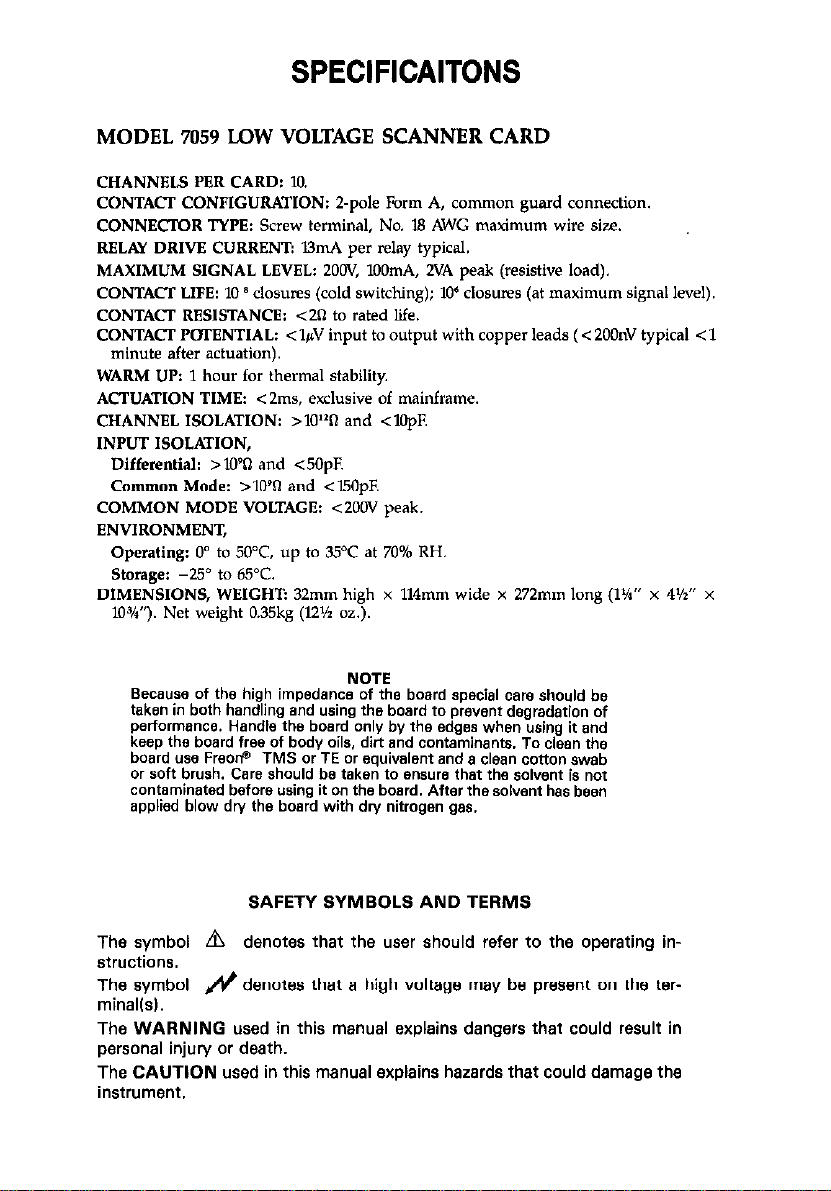
MODEL 7059 LOW VOLTAGE SCANNER CARD
CHANNELS PER CARD: 10.
CONTACT CONFIGURATION: Z-pole Form A, common guard connection.
CONNECTOR TYPE: Screw terminal, No. 18 AWG maximum wire size.
RELAY DRIVE CURRENT: UmA per relay typical.
MAXIMUM SIGNAL LEVEL: ZOOV, lOOmA, 2VA peak (resistive load).
CONTACT LIFE: IO 8 &sues (cold switching); 10’ closuvs (at maximum signal level).
CONTACT RESISTANCE: <Zfl to rated life.
CONTACT POTENTIAL: <l&J input to output with copper leads (< 2OOnV typical < 1
minute after actuation).
WARM UP: 1 hour for thermal stability
ACTUATION TIME: <2ms, exclusive of mainframe.
CHANNEL ISOLATION: >lOl*fI and <lO@
INPUT ISOLATION,
Differential: >109fl and 40pF.
Common Mode: >lOQ and <15OpE
COMMON MODE VOLTAGE: <ZOOV peak.
ENVIRONMENT,
Operating: 0” to 50°C. up to 35’C at 70%
Storage: -25” to 65°C.
DIMENSIONS, WEIGHT: 32mm
10%“). Net weight 0.35kg (12% oz.).
high x 114mm wide x 272mm long (1%” x 4’lr” x
RH.
Bec.wse of the high impedance of the board special care should be
taken in both handling and using the board to prevent degradation of
performance. Handle the board only by the edges when using it and
keep the board free of body oils. dirt and contaminants. To clean the
board use FreorP TMS or TE or equivalent and a clean cotton swab
or soft brush. Care should be taken to ensure that the solvent is not
contaminated before using it on the board. After the solvent has been
applied blow dry the board with dry nitrogen 888.
SAFETY SYMBOLS AND TERMS
The symbol m denotes that the user should refer to the operating instructions.
The symbol & denotes that a high voltage may be present on the ter-
minallsl.
The WARNING used in this manual explains dangers that could result in
personal injury or death.
The CAUTION used in this manual explains hazards that could damage the
instrument.
NOTE
Page 4
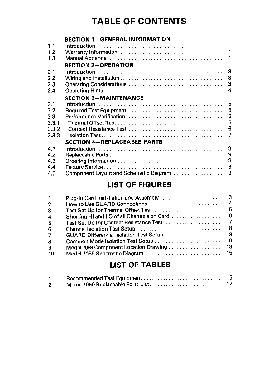
TABLE OF CONTENTS
SECTION l-GENERAL INFORMATION
Introduction ............................................
1.1
Warranty Information
1.2
ManualAddenda ........................................
1.3
SECTION Z-OPERATION
Introduction ............................................
2.1
Wiring and Installation
2.2
Operating Considerations .................................
2.3
Operating Hints
2.4
SECTION 3-MAINTENANCE
Introduction ............................................
3.1
Required Test Equipment
3.2
PerformanceVerification
3.3
3.3.1
3.3.2 Contact ResistanceTest
3.3.3 Isolation Test.
4.1
4.2
4.3
4.4
4.5
Thermal Offset Test
SECTION 4--REPLACEABLE PARTS
Introduction ............................................
ReplaceableParts ........................................
Ordering Information .....................................
Factory Service
Component Layout and Schematic Diagram .................
....................................
....................................
..........................................
.................................
..................................
.....................................
.................................
..........................................
..........................................
LIST OF FIGURES
5
5
5
z
7
9
9
9
9
9
Plug-In Card Installation and Assembly
1
How to Use GUARD Connections
2
Test Set Up for Thermal Offset Test
3
ShortingHIandLOofallChannelsonCard.. ................
4
Test Set Up for Contact Resistance Test
5
Channel Isolation Test Setup
6
GUARD Differential Isolation Test Setup
7
Common Mode Isolation Test Setup
6
Model 7058 Component Location Drawing
9
Model 7059 Schematic Diagram
10
..............................
...................... 3
.......................... 4
........................
........................
...........................
LIST OF TABLES
Recommended Test Equipment,,
1
Model 7059 Replaceable Parts List.
2
..........................
.........................
.....................
....................
...................
6
6
7
;
9
13
15
5
12
Page 5
SECTION 1
GENERAL INFORMATION
1.1 INTRODUCTION
The Model 7059 is a low-voltage scanner plug-in card which is fieldinstallable in the Model 705 and Model 706 scanner mainframes. The Model
7059 will switch up to 10 channels. For low-level transducer and thermo-
couple output switching the Model 7059 is designed to introduce a minimum
of thermal voltage error I < l&V input to output with copper leads). and ensure that high isolation (10% is maintained between input signals. Expected relay life (106 closures) is obtained when signals less than 1OV or
1OmA are switched. However, peak signals up to 2OOV or lOOmA may be
switched with the scanner. Quick disconnect screw terminals are used to
facilitate input and output connections to the scanner plug-in card (relay
cardl. The plug-in card is easily removed through the rear panel of the scanner mainframe.
1.2 WARRANTY INFORMATION
Warranty information is stated on the inside front cover of this manual. If there is
a need for service, contact the Keithley representative or authorized repair facility
in your area. Check the back cover of this manual for addresses. The service
form supplied at the end of the manual should be used to provide the repair
facility with adequate information concerning any difficulty.
1.3 MANUAL ADDENDA
Improvements or changes to this manual will be explained on an addendum
included with this manual.
Page 6

Page 7

SECTION 2
OPERATION
2.1 INTRODUCTION
This section provides information needed to use the Model 7069 with the
Model 705 and Model 706 mainframes.
2.2 WIRING AND INSTALLATION
1. Wiring Configuration-The Model 7059 has a guarded, Z-pole switching
configuration. The Model 7059 will switch any one of the 10 signals to
one output, or switch one signal to any one of 10 outputs.
A. Wiring is accomplished by means of barrier strip terminals.
6. Signal path resistance is typically less than 0.50 per contact; less than
2fI at end of life.
C. A guard surrounds all analog signal paths..
2. Installation- Refer to the Model 705 and Model 706 Instruction Manuals for
scanner card installation instructions.
2.3 OPERATING CONSIDERATIONS
1. Signal Level- 1OV peak, 1OmA peak with a resistive load for expected life.
Absolute maximum peak instantaneous rating: 2OOV. lOOmA, or 2VA
with a resistive load.
2. Isolation-Guarded interchannel resistance is nominally greater than
10t2fI and less than 1OpF at room temperature, at less than 70% relative
humidity.
3. Maximum Levels-200V peak between signal line pairs or from signal
lines to guard or mainframe (digital) common.
4. Operating Environment-O0 to 50°C up to 35OC at 70% relative humidity.
Figure 1. Plug-In Card Installation and Assembly
3
Page 8

2.4 OPERATING HINTS
The clamp-type screw terminals will accept up to #19 AWG wire. In order to
ensure thermal offset less than l$/ solid copper wires should be used
throughout the measurement hook-up.
To most effectively eliminate error voltages produced by leakage currents.
the GUARD terminal should be connected to the reference connection on
the channel which is most sensitive to error (that is, the one which has the
lowest source voltage versus the highest series resistance). For instance,
two sources are connected to the Model 7059; one having an equivalent
source of 1V with a series resistance of lOOk0, and the other having a source
voltage of .lV with a lkn series resistance. The lOOk source resistance will
develop 100 times the error voltage as the lkt3 source resistance, Its source
voltage however, is only ten times as large on the lV/lOOkn channel. The
GUARD would therefore be connected to the reference point of this channel
lsee Figure 21.
Reactances in the system will cause transients during switching. These
should not exceed the ratings given in the specifications. If they do, relay
contact life will be degraded.
Figure 2. How To Use GUARD Connection
4
Page 9

SECTION 3
MAINTENANCE
3.1 INTRODUCTION
This section contains a performance verification procedure. Since there is no
calibration adjustments, no recalibration is necessary. Recommended main-
tenance would include inspection of the scanner plug-in board and card-
edge connectors to ensure good electrical contact. In industrial environments annual cleaning using dry nitrogen gas and FreonO TMS or TE is
recommended. The verification procedure should be performed every 12
months or at the time maintenance is performed on the mainframe.
3.2 REQUIRED TEST EQUIPMENT
Recommended test equipment is given in Table 1, Test equipment other
than recommended may be substituted if specifications equal or exceed the
stated characteristics.
Table 1. Recommended Test Equipment
Hinimum Specification
I
!ero drift less than
i
150nV.
Thermal Cable
TTL compatible square
wave to 10Hz. and 1
pulse per 30 min.
ItI Sensitivity
rriggered Sweep TEK
IO.OOV, 1OOVDC
1U’OA Sensitivity
3.3 PERFORMANCE VERIFICATION
This section gives procedures needed to verify that the operation of the
Model 7059 is within specifications. The thermal offset should be carried out
in a temperature controlled environment of 23O f 1°C. Other tests may be
performed within environmental limits given in the specifications.
3.3.1 Thermal Offset Test
dFG
H-P 70358
Model
KI 181
i
KI 1488
KI 1506
705
195
1641
000 seriu
KI
KI
230
i14 or 61
1. The input of the Model 181 should be shorted with the Model 1488 shorting plug. After power is applied, the Model 181 should be allowed to
stabilize for four hours. During this time the analog output of the Model
5
Page 10

181 should be connected to the chart recorder end a recording made to
establish a baseline for the voltage measurements lsee Figure 3).
2. The 10 input connections on the Model 7059 plug-in card should be
shorted together between HI end LO with a short piece of solid copper
wire. That is, connect all the HI and LO terminals together es shown in
Figure 4. (The OUTPUT terminals of the Mods1 7059 should be connected
to short copper wires to facilitate connecting the alligator clips on the
Model 1506 cable.) With the Model 1506 cable attached to the output, the
plug-in card should then be inserted into the mainframe and power ap-
plied to the mainframe. Set the Model 705 to the reset mods and allow it
to warm up along with the Model 181.
3. After the warm up time has elapsed and a stable baseline is visible on the
chart recorder, the shorting plug on the Model 181 should be removed
and the Model 1506 cable from the Model 7059 connected in its place.
Set the Model 705 scanner mainframe to Channel 1, Channel mode and
the Single program mode. The scanner mainframe should now be clocked
et a rate of 1 channel every 15 (900 second interval time) minutes. The
thermal EMF generated in each channel will be visible as deflection from
the baseline on the recording. The meximum deflection should be no
more than f IfiV from the baseline for any channel.
ANALOG OUTPUT
Figure 3. Test Set Up for Thermal Offset Test
OTHER
CHANNELS
Figure 4. Shorting HI and LO of all Channels on the Card
3.3.2 Contact Resistance Test
1. Set up-Connect a short II” or less) piece of copper wire (#18 AWG) to
the input and also the output of the pole (signal HI or LO) or the channel
to be tested (see Figure 5 for the test set up diagraml.
2. Zero the Model 195 with the Model 1641 lesds shorted together.
3. After the Model 195 is zeroed connect the leads from the Model 195 to the
barrier strips on the Model 7059 vie the short piece of copper wire on the
terminal strips. Arrange the leads such that the plug-in card can be inserted into the Model 705 mainframe without disturbing the test lead connections to the terminal strips.
6
Page 11

4. Insert the Model 7059 into the mainframe, apply power end select the
channel which is tc be tested. The total signal path resistance can now be
measured. The reading should be <0.5fl upon initial shipment from the
factory end ~213 after usage.
Figure 5. Test Set Up For Contact Resistance Test
3.3.3 Isolation Test
Channel Isolation
A. This test rneesures the leakage resistance between two channels on the
board. One channel is tc be open end the other closed. Set up the test
circuit shown in Figure 6.
6. Short the HI and LO connections of each channel on the Model 7059.
C. Set the Model 705 tc the Channel mode, Channel 1 and the Step mode.
Set the electrometer tc Amps end prcgrem the Model 230 tc cutput
IOOV. Take the electrometer cut of ZERO CHECK. Program Channel 1 es
open and the other channels es closed.
D. Take the reading on the electrometer. The reading should be less than
1 x 10.loA. Using Ohm’s Law calculate the channel isolation. For example: R = E/I = lOOVl1 x 10.t0A = 1 x 10120. Due tc the capacitance of
the circuit, the offset current may be high until the capacitance of the cir-
cuit is charged up. Wait until the readings settle cut.
E. Manually scan through Channel 1 through 10 repeating step C and D for
each channel.
input Isolation, Differential (Guarded)
A. This test measures the differential input isolation which is the leakage
resistance between a guarded channel’s HI end LO connections. Set up
the test circuit shown in Figure 7.
6. Set the Model 705 tc the Channel mode, Channel 1 end the Step mode.
Set the electrometer tc Amps end prcgram the Model 230 tc output
1OOV. Take the electrohi’dter cut of ZERO CHECK.
C. Take the reading on the Blectrometer. The reading should be less then
1 x IOJA. Using Ohm% Law celculate the isolation (leakage resistance).
For example: R = E/l = lOOV/lrSA = 1 x IO%. Due tc the capacitance
of the circuit, the offset current may be high until the capacitance is
charged up. Wait until the readings settle cut.
D. Manually scan Channels 1 through 10 repeating step 6 end C for each
channel.
7
Page 12

Input Isolation, Common Mode
A. This test measures the leakage resistance between signal lines and power
line ground. Set up the test circuit shown in Figure 8.
El Short the input HI end LO terminals of each channel with a short piece of
solid copper wire. Do not connect the channels together, just short the
HI and LO terminals.
C. Insert the Model 7059 into the mainframe and set the Model 705 to the
Channel mode, Channel 1 and the Step mode.
D. Set the electrometer to Amps and program the Model 230 to output
100VDC. Take the electrometer out of ZERO CHECK.
E. Take the reading on the electrometer. The reading should be less than
1 x lo-7A. Using Ohm’s Law calculate the isolation (leakage resistance).
For example: R=E/I = lOOVl1 x IO-7A = 1 x10X2. Due to the
capacitance of the circuit, the offset current may be high until the
capacitance is charged up. Wait until the readings settle out.
F. Manually scan Channels 1 through 10 repeating step D and E for each
channel.
a
ELECTRO- “I
METER
MY OR 619,
SET TO
AMP6 LO
Figure 6. Channel Isolation Test Set Up
Page 13

MODEL 70517059
Figure 7. GUARD Differential Isolation Test Set UP
MODEL 705/7059
CHANNEL UNDER
TEST
Figure Lt. Common Mode Isolation Test Set Up
9
Page 14

SECTION 4
REPLACEABLE PARTS
4.1 INTRODUCTION
This section contains replacement parts information, e schematic diagram
and component layout for the Model 7059.
4.2 REPLACEABLE PARTS
Parts ere listed alpha-numerically in order of their circuit designation. Table 2
contains parts list information for the Model 7059.
4.3 ORDERING INFORMATION
To place en order, or to obtain information concerning replacement parts,
contact your Keithley representative or the factory. See the inside front
cover for addresses. When ordering include the following information:
1. Instrument Model Number
2. Instrument Serial Number
3. Part Description
4. Circuit Description (if applicable)
5. Keihtley Part Number
4.4 FACTORY SERVICE
If the instument is to be returned for service, please complete the service
form which follows this section and return it with the instrument.
4.6 COMPONENT LAYOUT AND SCHEMATIC DIAGRAM
Figure 9 contains e component layout of the Model 7059 while, Figure 10
contains the Model 7059 schematic diagram.
11
Page 15

Table 2. Model 7059 Replaceable Parts
Keithley
Part No.
Capacitor, 1OuF. 25V, Aluminum Electrolytic
JlOOl
JlOOZ
J1003 3 pin Terminal Strip
J1004
J1005
KlOl Relay
K102 Relay
K103 Relay
K104 Relay
K105 Relay
K106 Relay
K107 Relay
K106 Relay
K109 Relay
KllO Relay
3 pin Terminal Strip (2 required)
IO pin Terminal Strip (3 required)
10 pin Terminal Strip
10 pin Terminal Strip
MECHANICAL PARTS
Clamp, Assembly, Upper
a. Clamp, Upper
b. Strip, Rubber
Clamp, Assembly, Lower
a. Clamp, Cable, Lower
b. Strip, Rubber
No. 6-32 x 5/16 Phillips Pan Head Screw
(2 required)
No. 6-32 x 1 Phillips Pan Head Screw
(2 required)
c-314-10
CS-457-2
cs-457-l
cs-475-l
05-457-2
CS-457-2
RL-77
RL-77
RL-77
RL-77
RL-77
RL-77
RL-77
RL-77
RL-77
RL-77
7055-303-03
7055.305
26621
7055.306
7055.307
26621
12
Page 16

d:
k
Figure 9. Model 7059 Component Location Drawing
13114
Page 17

Figure 10. Model 7069 Schematic Diagram
15116
Page 18

Page 19

 Loading...