

Page 1

Model 7054 High Voltage
Scanner Card
Instruction Manual
Contains Operating and Servicing Information
Page 2

WARRANTY
Keithky Instruments, Inc. warrants this product to be free from defects in material and workmanship for a period of 3 years fmm
date of shipment.
Keithky Inshuments, Inc. warrants the following items for 90 days from the date of shipment: probes, cables, rechargeable batteries, diskettes, and documentation.
During the warranty period, we will, at our option, either repair or replace any product that proves to be defective.
To exercise this warranty, write or call your local Keithley representative. or contact Keitbley headquarters in Cleveland, Ohio. You
will be given prompt assistance and return instructions. Send the product transportation prepaid, to the indicated service facility.
Repairs will be made and the pmduct retomed, transportation prepaid. Repaired or replaced products are warranted for the balance
of the orighd warranty period, or at least 90 days.
LIMITATION OF WARRANTY
This warranty does not apply to defects resulting from product modification without Keithley’s express written consent, or misuse
of any product or part. Tbis warranty also does not apply to fuses, software. non-rechargeable batteries, damage from battery leakage., or problems arising from normal wear or failurc to follow instructions.
THISWARRANTYISINLJELJOFALLOTHEXW-,
WARRANTY OF MERCHANTABILITY OR FITNESS FOR A PARTICULAR USE THE REMEDIES PROVIDED HEREIN
ARE BUYER’S SOLE AND EXCLUSIVE REMEDIES.
m KEZTHLEY INSTRUMENTS, INC. NOR ANY OF ITS EMPLOYEES SHALL BE LIABLE FOR ANY DIRECT,
INDIRECT, SPECIAL, INCIDENTAL OR CONS!ZQJENTlAL DAMAGES ARISING OUT OF THE USE OF ITS INSTRUMENTS AND SOFTWARE EVBN IF
POSSIBILITY OF SUCH DAMAGES. SUCH EXCLUDED DAMAGES SHALL INCLUDE, BUT ARE NOT LIMITED To:
COSTS OF REMOVAL AND INSTALLATION, LOSSES SUSTAINEZI AS THE RESULT OF INJURY TO ANY PERSON, OR
DAMAGE TO PROPERTY.
KFJTHLBY INSTRUMENTS, INC., HAS BEEN ADVISED IN ADVANCE OF THE
EXPRJZXED OR IMPLIED, INCLUDING ANY IMPLIED
Page 3

Model 7054 High Voltage Scannr Card
Instruction Manual
Q 1987, Keithley Instruments, Inc.
Test Instrumentation Group
All rights reserved.
Cleveland, Ohio, U.S.A.
February 1987, Third Printing
Document Number: 7054-901-01 Rec. C
Page 4

SAFETY PRECAUTIONS
The following safety precautions should be observed before using this
product and any associated instrumentation. Although some instruments
and accessories would normally be used with non-hazardous voltages,
there are situations where hazardous conditions may be present.
This product is intended for use by qualified personnel who recognize
shock hazards and are familiar with the safety precautions required to
avoid possible injury. Read the operating information carefully before using the product.
Exercise extreme caution when a shock hazard is present. Lethal voltage
may be present on cable connector jacks or test fixtures. The American
National Standards Institute (ANSI) states that a shock hazard exists
when voltage levels greater than 30V RMS, 42.4V peak, or 60VDC are
present. A good safety practice is to expect that hazardous voltage is
present in any unknown circuit before measuring.
Before operating an instrument, make sure the line cord is connected to a
properly grounded power receptacle. Inspect the connecting cables, test
leads, and jumpers for possible wear, cracks, or breaks before each use.
For maximum safety, do not touch the product, test cables, or any other
instruments while power is applied to the circuit under test. ALWAYS remove power from the entire test system and discharge any capacitors before: connecting or disconnecting cables or jumpers, installing or
removing switching cards, or making internal changes, such as installing
or removing jumpers.
Do not touch any object that could provide a current path to the common
side of the circuit under test or power line (earth) ground. Always make
measurements with dry hands while standing on a dry, insulated surface
capable of withstanding the voltage being measured.
Do not exceed the maximum signal levels of the instruments and accessories, as defined in the specifications and operating information, and as
shown on the instrument or test fixture rear panel, or switching card.
Do not connect switching cards directly to unlimited power circuits. They
are intended to be used with impedance limited sources. NEVER connect
switching cards directly to AC main. When connecting sources to switching cards, install protective devices to limit fault current and voltage to
the card.
Page 5
When fuses are used in a product, replace with same type and rating for
continued protection against fire hazard.
Chassis connections must only be used as shield connections for measur-
ing circuits, NOT as safety earth ground connections.
If you are using a test fixture, keep the lid closed while power is applied
to the device under test. Safe operation requires the use of a Bd interlock.
If a @ screw is present on the test fixture, connect it to safety earth
ground using #18 AWG or Iarger wire.
The t symbol on an instrument or accessory indicates that IOOOV or
more may be present on the terminals. Refer to the product manual for de-
tailed operating information.
Instrumentation and accessories should not be connected to humans,
Maintenance should be performed by qualified service personnel. Before
performing any maintenance, disconnect the line cord and all test cables.
Page 6

SPECIFICATIONS
MODEL 7054 HIGH VOLTAGE SCANNER CARD
CHANNELS PER CARD: 10.
CONTACT CONFIGURATION: l-pole Form A, common guard connection.
CONNECTOR TYPE: Quick disconnect screw terminal, No. 18 AWG maximum
wire size.
RELAY DRIVE CURRENT: 50mA (per relay).
MAXIMUM SIGNAL LEVEL: lOOOV, 0.5A, 1OVA peak (resistive load).
CONTACT LIFE: 10” closures (cold switching); 10 6 closures (at maximum signal
level).
CONTACT RESISTANCE: c 1l-l.
ACTUATION TIME: <2Oms, exclusive of mainframe.
CHANNEL ISOLATION: > 10’9 and c 10pF.
INPUT ISOLATION: > 109R and < 150pF.
GUARD TO CHASSIS VOLTAGE: 200V maximum.
ENVIRONMENT:
Operating: 0” to SOT, up to 35°C at 70% non-condensing relative humidity.
Storage: -25” to t7O”C.
DIMENSIONS, WEIGHT: 32mm high x l&run wide x 272mm long (l*/(” x 44’2”
x 10%“). Net weight 0.28kg (10 oz.).
Specifications subject to change without notice.
Page 7
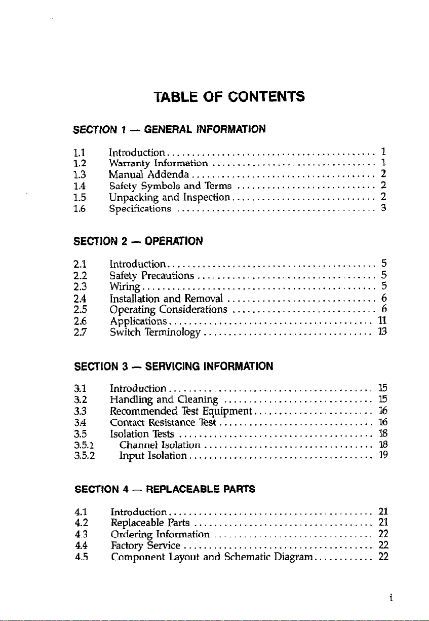
TABLE OF CONTENTS
SEcmON i-
1.1
1.2
1.3
1.4
1.5
1.6
SECTION 2 - OPERATION
2.1
2.2
2.3
2.4
2.5
2.6
2.7
SECTION 3 - SERVICING INFORMATION
3.1
3.2
3.3
3.4
3.5
3.5.1
3.5.2
Introduction.
Warranty Information
Manual Addenda
Safety Symbols and Terms
Unpacking and Inspection.
Specifications
Zntroduction..............................~
Safety Precautions
Wiring.
Installation and Removal
Operating Considerations
Applications.
Switch Terminology
Introduction
Handling and Cleaning
Recommended Test Equipment.
Contact Resistance Test
Isolation Tests
GENERAL INFORMATION
.........................................
..................................... 2
........................................
....................................
..............................................
........................................
..................................
.........................................
.......................................
Channel isolation
Input Isolation,
..................................
.................................... 19
.................................
............................
............................ 2
..............................
.............................
..............................
....................... 16
............................... 16
...........
1
1
2
3
5
5
5
6
6
11
13
l5
15
‘18
18
SECTION 4 -
Introduction
ii
4.3
4.4
4.5
Replaceable Parts..
Ordering Information
Factory Service
Component Layout and Schematic Diagram.
REPLACEABLE PARTS
.........................................
..................................
................................
......................................
...........
21
22
22
22
22
Page 8
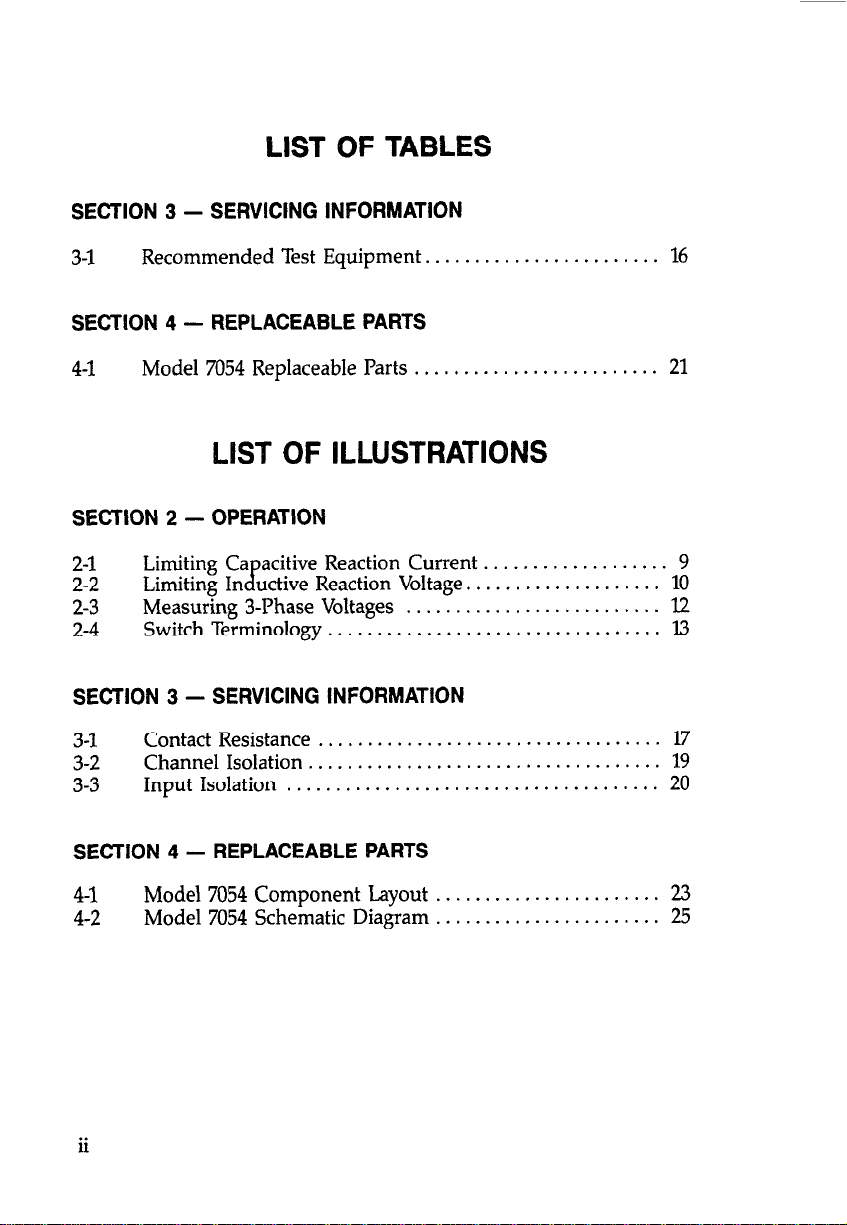
LIST OF TABLES
SECTION 3 -
3-1
SECTION 4 -
4-1
Recommended Test Equipment. . . . . . . . . . . . . . . . . . . . . . . . 16
Model 7054 Replaceable Parts . , . . . . . . . . , . . . . . . . . . . . . . . 21
SERVICING INFORMATION
REPLACEABLEPARTS
LIST OF ILLUSTRATIONS
SECTION 2 - OPERATION
2-1
2-2
2-3
2-4
SECTION 3 -
3-l
3-2
3-3
Limiting Ca
Limiting In
Measuring 3-Phase Voltages
Switch Terminology
Contact Resistance
Channel Isolation
Input Isolation
acitive
cp
uctive Reaction Voltage.
SERVICING INFORMATION
.................................... 19
......................................
Reaction Current
..........................
..................................
...................................
...................
...................
9
10
12
13
17
20
SECTION 4 -
4-1
4-2
ii
Model 7054 Component Layout . . . . . . . . . . . . . . . . . . . . . . . 23
Model 7054 Schematic Diagram . . . . . . . . . , . . . . . . . . . . . . . 25
REPLACEABLE PARTS
Page 9
SECTION 1
GENERAL INFORMATION
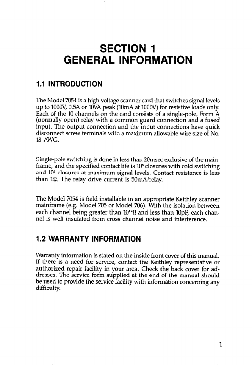
1.1 INTRODUCTION
The Model 7054 is a high voltage scanner card that switches signal levels
up to lOOOV, 0.5A or 1OVA peak (lOmA at 1OOOV) for resistive loads only.
Each of the 10 channels on the card conSists of a single-pole, Form A
(normally open) relay with a common guard connection and a fused
input. The output connection and the input connections have quick
disconnect screw terminals with a maximum allowable wire size of No.
18 AWG.
Single-pole switching is done in less than 20msec exclusive of the main-
frame, and the specified contact life is 10B closures with cold switching
and lo6 closures at maximum signal levels. Contact resistance is less
than 10. The relay drive current is 50mAlrelay.
The Model 7054 is field installable in an appropriate Keithley scanner
mainframe (e.g. Model 705 or Model 706). With the isolation between
each channel being greater than 1O”Q and less than lOpF, each channel is well insulated from cross channel noise and interference.
1.2 WARRANTY INFORMATION
Warranty information is stated on the inside front cover of this manual.
If there is a need for service, contact the Keithley representative or
authorized repair facility in your area. Check the back cover for addresses. The service form supplied at the end of the manual should
be used to provide the service facility with information concerning any
difficulty.
Page 10
1.3 MANUAL ADDENDA
Product improvements or changes to this manual will be explained on
an addendum included with the manual. It is recommended that this
information be incorporated immediately into the appropriate places
in the manual.
If an additional instruction manual is required, order the manual
package (Keithley Part Number 7054-901-00). The manual package includes an instruction manual and all pertinent addenda.
1.4 SAFETY SYMBOLS AND TERMS
The symbol !
operating instructions.
The symbol
terminals.
The WARNING used in this manual explains dangers that could result
in personal injury or death.
The CAUTION used in this manual explains hazards that could damage
the instrument.
A on the card denotes that the user should refer to the
denotes that a high voltage may be present on the
AIM
1.5 UNPACKING AND INSPECTION
The Model 7054 was inspected both electrically and mechanically before
shipment. Upon receiving the Model 7054, unpack all items from the
shipping carton and check for any obvious damage that may have occurred during transit. Report any damage to the shipping agent. Retain and use the original packaging materials in case reshipment is
necessary. The following items are shipped with every Model 7054:
Model 7054 High Voltage Scanner Card
Model 7054 Instruction Manual
Page 11

1.6 SPECIFICATIONS
Detailed specifications of the Model 7054 precede the Table of Contents
of this manual.
314
Page 12

SECTION 2
OPERATION
2.1 INTRODUCTION
This section provides information needed to use the Model 7054 High
Voltage Card with the Model 705 and 706 scanner mainframes. Once
the card is installed in the mainframe, refer to the mainframe instruc-
tion manual for complete operating instructions.
2.2 SAFETY PRECAUTIONS
WARNING
User supplied lethal voltages may be present on the PC
board or the connections. Turn off all power and
discharge stored energy in external circuitry before making or breaking connections.
1. Do not exceed the Model 7054 maximum voltages of ltlOOOV peak
terminal to terminal and &l35OV peak terminal to chassis.
2. Make sure the scanner mainframe is grounded through an earth
grounded receptacle before operation.
3. Ins
4. Use appropriately rated cables when switching high voltages.
ect alI test lead connections for wear and defects such as cracks
an f
exposed wires.
2.3 WIRING
Each channel on the Model 7054 card consists of a single-pole, Form
A (normally open) switching relay. The Model 7054 will switch any one
of the 10 signals (inputs) to one output, or switch one signal to any
one of 10 outputs.
Page 13

NOTE
Because of the high impedance of the board, take special
care when handling and using to prevent degradation of
performance. Handle the board by the edges to avoid contaminating it with dirt, body oil, etc. For cleaning instructions, see paragraph 3.2.
1. Wiring is accomplished by means of terminal strips as shown on the
component layout. See Figure 4-1. Each channel has a HI connection and a LO (GUARD) connection. Lb (Guard) is common to all
channels.
2. Resistance of the relay contacts path is less than 10.
3. A common guard surrounds all analog signal paths.
4. Use wires or cables that are rated for greater than 1OOOV. The maximum allowable wire size is No. 18 AWG. The minimum wire size
is No. 26 AWG.
5. Route the wires through the rubber clamp pads located at the rear
of the card.
2.4 INSTALLATION AND REMOVAL
Once the card is wired, insert it card edge first into the scanner mainframe by aligning it with the grooves in the appropriate slot. Make sure
it is properly seated into the mainframe connector. Push the locking
tabs forward to the center of the card to lock it in.
To remove a card, first turn off the mainframe and all other equipment
connected to the card. Unfasten the locking tabs on the card by pulling the tabs outward. Grasp the end of the card and carefully pull it
out of the mainframe.
2.5 OPERATING CONSIDERATIONS
Since the Model 7054 is a lo-channel card, set the scanner to the 2-pole
mode when using the Model 7054 by itself or when intermixing with
Page 14

other lo-channel cards (such as Models 7056, 7058, 7059, and 7066). In
the 2-pole scanner mode, each scanner channel controls one channel
on one lo-channel card.
Signal Levels-The maximum signal levels for the Model 7054 High
Voltage Card are 1OOOV maximum, 0.5A or 1OVA l eak (1OmA at 1OOOV)
for resistive loads only. The specified contact 1’ e is lO* closures with
cold switching and lo6 closures at maximum signal levels.
WARNING
When switching signals greater than 30V RMS or 42.2V
peak take care to prevent contact with live circuits which
could cause electrical shock resulting in injury or death.
Cables-Shielded cables should be used with the Model 7054 card when
switching above 50V. The shield should be connected to the circuit LO
(GUARD). This prevents excessive radiation from the cables from in-
terfering with any equipment. The cables must be rated for greater than
1ooOV.
Fusible Links-The Model 7054 scanner card has a fusible link in series
with the high input side of each channel relay. A link opens when the
current level on that channel becomes excessive because of an external
circuit misapplication or a relay failure. The links protect the PC board
from damage that is difficult to repair (e.g. lifted or burned traces on
the board).
The links are covered with Plexiglas@ shields to prevent mechanical
damage and still provide a visual check. A repair procedure follows:
1. Unscrew the Plexiglas@ shield. Clean out the PC board feedthru
holes for the fusible link with a desoldering tool.
2. Insert a jumper of No. 38 AWG magnet wire into the holes and solder
in place.
Page 15

CAUTION
When replacin the fusible links, use only No. 38 AWG
magnet wire. 18 se of any other wire may cause severe
damage to the PC board.
3. Check the same channel’s relay contacts for a short or insufficient
input isolation resistance and replace the relay if necessary.
4. Clean the PC board and Plexiglas
@ shield according to the instruc-
tions given in paragraph 3.2, then remount the shield.
Depending on your application, a current limiting resistor can be used
in place of a fusible link. Each resistor will limit the current flow through
one channel. The resistors must be of sufficient power rating to safely
dissipate any overload.
Reactive Loads-The Model 7054 is specified for resistive loads. Since
reactive loads can cause excessive currents and voltages, current surge
limiting (for capacitive loads) and voltage clamping (for inductive loads)
are required to prevent damaging the relays and external circuitry.
1. Ca acitive Loads - The surge current from a ca acitive load must
be ess than 0.5A to protect the relays. Figure 2- P
P
shows typical circuits to limit current surges. Also, consider the maximum load of
1OVA when determining the current limit. For example, when switching 5OOV, the current must be limited to 2OmA (I = lOVA/5OOV) and
the limiting resistor calculation of Figure 2-lA would be:
R = VII = 5OWl2OmA = 25k!J
2. Inductive Loads - Inductive reaction voltage, L(di/dt), must be less
than 1OOUV. Typical clampin circuits are shown in Figure 2-2. Also,
consider the maximum loa B of 1OVA when determining the voltage
limit. For example, when switching 4OmA, the voltage must be
limited to 250V (V = lOVA14OmA) and the clamping resistor calculation of Figure 2-2A would be:
R = VII = 25OVl4OmA = 625On
Page 16

A. RESISTOR LIMITED
IN
0
L
l HIGH RESISTANCE COLD.
LOW RESISTANCE HOT.
FAST THERMAL RECOVERY.
B. THERMISTOR LIMITED
Figure 2-l. Limiting Capacitive Reaction Current
LOAD
9
Page 17

LOAD
A. RESISTOR CLAMPED (AC OR DC VOLTAGES)
B. DIODE CLAMPED (DC VOLTAGES)
C. ZENER CLAMPED (AC VOLTAGES)
LOAD
D. RESISTOR-CAPACITOR CLAMPED (AC VOLTAGES)
Figure 2-2. Limiting Inductance Reaction Voltage
10
Page 18

2.6 APPLICATIONS
The Model 7054 can monitor high voltages from ten different circuits
or switch a high voltage source to ten separate circuits.
CAUTION
Because of the high voltage applications of the Model
7054, only one channel relay should be energized at a
time. If the break before make operation of the scanner
channels is hindered by the application, the card could
be damaged.
As an example of measuring high voltages, consider the sensing application shown in Figure 2-3. Three-phase line or load voltages are switched
by the Model 7054 for monitoring. Since LO is common to all channels
and the output of the card, only one of the channel LOS is connected.
To prevent card damage, voltage clamping is necessary when monitor-
ing line voltages. Current limiting or voltage cIamping are necessary
when measuring capacitive or inductive loads. Put the protection cir-
cuitry between the source of the transient and the card.
An example of switching a high voltage source is given in Application
Note #700, “Switching in Multipoint Testing”. A Model 7054 and a
divider network are used to incrementally increase the output of a
Model 247 High Voltage Supply.
This application is suitable for tests such as insulation resistance of
cables, harnesses, and PC boards, high-pot testing, and breakdown
testing on semiconductors.
11
Page 19

MODEL 7054 IN SCANNER MAINFRAME
CHANNEL
HI LO HI LO HI LO HI LO
L
CHANNEL
CHANNEL 0uTPLrr
Figure 2-3. Measuring 3-Phase Voltages
Page 20

2.7 SWITCH TERMINOLOGY
Terms used to describe switch configurations (see Figure 2-4) are defined
as follows:
1. Form A is a single-pole, normally open (SPNO) switch. A Zpole,
normally open switch is called 2 Form A.
2. Form B is similar to krm A except that its contacts are normally closed
(SPNC). A 2-pole, normally closed switch is called 2 Form B.
3. Form C is a sin le-
figuration is c
ole, double-throw switch (SPILT). A 2-pole con2 Form C.
z!iB e
FORM A
(SPNO)
FORM B
(SPNC) -
SINGLE-POLE. NORMALLY CLOSED
FORM C
(SPDT)
--
SINGLE-POLE, NORMALLY OPEN
0
SINGLE-POLE, DOUBLE-THROW
Figure 2-4. Switch Terminology
Page 21

SECTION 3
SERVICING INFORMATION
3.1 INTRODUCTION
This section describes tests for verifying the performance of the Model
7054. The tests include:
l Functionality test
or shorted relays or bad connections.
l Specification tests - Two isolation tests measuring leakage currents
to check for a contaminated board and possibly bad relays.
Perform these tests in an environment within the specified operating
temperature range (0” to 35°C up to 70% RH) of the scanner card.
Do not perform the procedures in this section unless
you are a qualified service person. Some of the procedures may expose you to potentially lethal voltages
(> 30V RMS) that could result In personal Injury or death
if normal safety precautions are not observed.
Recommended maintenance includes inspection of the scanner card
and the card edge connector to ensure good electrical contact. The
Model 7054 does not require calibration.
- Measuring contact resistance to check for open
WARNING
3.2 HANDLING AND CLEANING
Because of the high impedance of the board, take special care when
handling and using to prevent degradation of performance. Handle the
board by the edges to avoid contaminating it with dirt, body oil, etc.
Page 22

To clean the board, spray on an uncontaminated solvent, such as
Freon@ TMS or TE and clean with cotton swabs or a soft brush. After
the solvent has been applied and is stiIl liquid, blow-dry the board with
dry nitrogen gas.
3.3 RECOMMENDED TEST EQUIPMENT
Table 3-l lists recommended test equipment for performance verification. Other test equipment may be substituted if specifications equal
or exceed those stated.
NOTE
Since the Model 617 electrometer has an internal 1OOV
source, it can be used in the V/I mode instead of the Model
614 electrometer and Model 230 voltage source.
Table 3-1. Recommended Test Equipment
Description Specification Mfr.
Scanner Mainframe Extender Card DMM
Voltage Source l.OOVDC
Electrometer lo-‘OA
<IQ sensitivity
Keithley 705 or 706
Keithley
Keithley
Keithley 230
Keithley 614 or 617
Model
7061
196
3.4 CONTACT RESISTANCE TEST
This test measures the resistance of each relay contact in an opened
and closed state.
1. Set up the equipment as shown in Figure 3-l. Short the HI terminal
to the LO terminal of each channel. Attach two copper wires to the
output HI and Lo terminals.
Page 23

2. Zero the Model 196 with the Kelvin test leads shorted together.
3. Set the channel mainframe to the channel mode, channel 1, and the
step mode. Close channel 1 from the scanner front panel. The reading
on the Model 196 should indicate a short circuit (less than 1Q).
4. Open channel 1 from the scanner front panel. The reading on the
Model 196 should indicate an open circuit.
5. Repeat steps 3 and 4 for the remaining channels on the card.
r
MODEL 7054 IN SCANNER MAINFRAME
CHANNEL
UNDER TEST
t
HI LO
KELVIN TEST LEADS ___)
OuTPur
HI LO
Figure 3-1. Contact Resistance
Page 24

3.5 ISOLATiON TESTS
The two isolation tests measure leakage currents for calculating leakage
resistances on the Model 7054. With the Model 7061 Universal Adpater
Card, these tests can be performed faster.
3.5.1 Channel Isolation
This test measures the leakage current between two channels.
1. Set up the equipment as shown in Figure 3-2.
2. Set the scanner to channel 1 and the step mode. Program channel
1 open and the other channels as closed.
3. Set the electrometer to amps and zero check. Program the Model
230 to output 1OOV. Take the electrometer out of zero check.
4. The electrometer should read less than 10~‘OA. (Due to the capacitance
of the circuit, the offset current may be high until the circuit
capacitance is charged up. Wait until the readings settle out.)
5. Using Ohms law, calculate the channel isolation (the leakage
resistance between two channels). For example:
R = E/I = 100VllO-‘“A = XP2n
NOTE
With the Model 617 electrometer in V/I mode, the resistance
is calculated automatically.
6. Put the Model 230 in standby mode and set the electrometer to zero.
7. Repeat steps 2 through 6 for the remaining channels.
la
Page 25

h4ODEL 7054 IN SCANNER MAINFRAME
WANNEL
UNDER TEST
Figure 3-2. Channel Isolation
3.52 input Isolation
HI
10
OUTPUT
HI
!
This test measures the leakage current between a channel’s HI and Lo
terminals.
1. Set up the equipment as shown in Figure 3-3.
2. Set the scanner to channel 1 and the step mode. Program all channels as open,
3. Set the electrometer to amps and zero check. Program the Model
230 to output 1OOV. Take the electrometer out of zero check.
4. The electrometer should read less than 10-‘A. (Due to the capacitance
of the circuit, the offset current may be high until the circuit
capacitance is charged up. Wait until the readings settle aut.)
19
Page 26

5. Using Ohm’s law, calculate the input isolation (leakage resistance)
for this channel. For example:
R = E/I = lOOV/lO-‘A = 10gQ.
NOTE
With the Model 677 electrometer in VII mode, the resistance
is calculated automatically.
6. Put the Model 230 in standby mode and set the electrometer to zero.
7. Repeat steps 2 through 6 for the remaining channels.
MODEL 7054 IN SCANNER MAINFRAME
CHANNEL
UNDER TEST
HI
lo
OUTPUT
HI
20
Figure 3-3. input Isolation
Page 27

SECTION 4
REPLACEABLE PARTS
4.1 INTRODUCTION
This section contains replacement parts information, a component
layout, and a schematic diagram for the Model 7054.
4.2 REPLACEABLE PARTS
Table 41 Lists parts alphanumerically in the order of their circuit designa-
tions.
Table 4-1. Model 7054 Replaceable Parts
Circuit
Desig.
Cl01
JlOOl
J1002
J1003
KlOlKllO
SQlOlSQllO
Keithley
Description
Capacitor, lOpF, 25V, Aluminum Electrolytic C-314-10
Connector cs-464-1
Connector
Connector
Relay, Single-Pole Form A
Fusible Link, No. 38 AWG Magnet Wire
Plexiglas* Shield 7054-302
Upper Clamp Assembly
Lower Clamp Assembly 7055-308
Part No.
CS-464-2
cs-464-2
RL-76
-
7055-303-05
Page 28

To place an order or to obtain information about replacement parts, contact your Keith@ representative or the factory. See the back cover for
addresses. When ordering, include the following information:
l Model number
l Serial number
l Part description
l Circuit description (if applicable)
l Keithley part number
4.4 FACTORY SERVICE
If fault can be isolated to a particular card, then it is sufficient to return
just the card(s). Otherwise, send back both the card(s) and the scanner mainframe. For service, photocopy and complete the service form
which follows this section and return it with the equipment.
4.5 COMPONENT LAYOUT AND SCHEMATIC DIAGRAM
Figure 41 shows a component layout of the Model 7054. Figure 42
shows the schematic diagram of the Model 7054.
22
Page 29

-.-.-
r-------7
L------A
b
%
;z
1
EO
-
-
N
I
(1
I
*
t
n
I
Figure 4-1. Model 7054 Component Layout
D
I
23124
Page 30

\
5
W-t-F.S*
J
--
.ALL CAPACITOR VALUES AFIE v( WCROFAFWS
I
UNLESS OTHERWISE MARKED (p~-P~~OF~R~DS.).
DENOTES DIGITAL COMMON.
!.v
6
YATES WITH JIOIZ OR JIOU
ON MAlNFRUlE OF HCiXLi’C6
Figure 4-2. Model 7054 Schematic Diagram
COMMON
/
25126
Page 31

Service Form
Model No.
Serial No. i Date
Name and Telephone No.
Company
List all control settings, de&be problem and dwk boxes tkt apply to problem.
cl Jntermittent
P IElzfaillue 0 Obvious problem on power-up
a Fmnt panel operational
Display or output (check one)
LIDrift.
0 Unstable D Wtinot read applied input
cl Overload
cl calibration only cl Certificate of aliiration required
P Datarequired
(attach any additicmal sheets as necessary)
show a block diagram of your me
Also, desaibe signal sowx.
cl An&g output fOllOWJ display
0 All ranges or functions are bad
p Unable to zero
ammnent system includiig all instruments mnnected (whether power is hmwd on or not).
0 l’artlcular range or function bad; specify
0 Batteries and fuses are OK
..-_.
0 Checked all cables
_-__ - -.l^_lll. --
where is the measurement b&g perfomxd? (factory, mnbolled laboratory, out-of-dwm, etc.)
what power Line voltage is used?
Any additional information (Jf special modifications have been made by the user, please desaibe.)
Ambient temperahue?
- ~
OF
Page 32

Keithley Instruments, Inc.
Test Instrumentation Group
28775 Aurora Road
Cleveland, Ohio 44139
Printed in the U.S.A.
 Loading...