

Page 1

Instruction Manual
Model 705 Scanner
Contains Operating and Servicing Information
705-001-01 Rev. F/ 4-00
Page 2

WARRANTY
Keithley Instruments, Inc. warrants this product to be free frqm defects in material and workmanship for a period of I year
from date of shipment.
Keithley Instruments, Inc. warrants the following items for 90 days from the date of shipment: probes, cables, rechargeable
batteries, diskettes, and documentation.
During the warranty period, we will, at our option, either repair or replace any product that proves to be defective.
To exercise this warranty, write or call your local Keithley representative, or contact Keithley headquarters in Cleveland, Ohio.
You will be given prompt assistance and return instructions. Send the product, transportation prepaid, to the indicated service
facility. Repairs will be made and the product returned, transportation prepaid. Repaired or replaced products are warranted for
the balance of the original warranty period, or at least 90 days.
LIMITATION OF WARRANTY
This warranty does not apply to defects resulting from product modification without Keithley’s express written consent, or
misuse of any product or part. This warranty also does not apply to fuses, software, non-rechargeable batteries, damage from
battery leakage, or problems arising from normal wear or failure to follow instructions.
THIS WARRANTY IS IN LIEU OF ALL OTHER WARRANTIE
S, EXPRESSED OR IMPLIED, INCLUDING ANY
IMPLIED WARRANTY OF MERCHANTABILITY OR FITNESS FOR A PARTICULAR USE. THE REMEDIES PROVIDED HEREIN ARE BUYER’S SOLE AND EXCLUSIVE REMEDIES.
NEITHER KEITHLEY LNSTRUMENTS, INC. NOR ANY OF ITS EMPLOYEES SHALL BE LIABLE FOR ANY DIRECT,
INDIRECT, SPECIAL, INCIDENTAL OR CONSEQUENTIAL DAMAGES ARISING OUT OF THE USE OF ITS
INSTRUMENTS AND SOFTWARE EVEN IF KEITHLEY INSTRUMENTS, INC.. HAS BEEN ADVISED IN ADVANCE
OF THE POSSIBILITY OF SUCH DAMAGES. SUCH EXCLUDED DAMAGES SHALL INCLUDE, BUT ARE NOT LIMITED TO: COSTS OF REMOVAL AND INSTALLATION, LOSSES SUSTAINED AS THE RESULT OF INJURY TO ANY
PERSO.N, OR DAMAGE TO PROPERTY.
Keithley Instruments, Inc. l 28775 Aurora Road l Cleveland, OH 44139 l m-248-0400 l Fax: 440-248-6168 l http://www.keithley.com
BELGIUM:
CHINA
FRANCE:
GERMANY:
GREAT BRITAIN:
[NIXA:
ITALY:
NETHEHLANDS:
SWITZERLAND:
TAIWAN:
Keittdey lnshuments B.V.
Keitbley Instruments China Yuan Chen Xin Building. Room 705 * 12Yumin Road. Dew& Madian * Beijing loo029 * 8610-62022886 *Fax: 8610.62022892
Keithley Instruments Sari
Keithley Instruments GmbH
Keitbley Instruments Ltd
Keithley Instruments GmbH
Keitbley Instruments s.r.1.
Keithley Instruments B.V.
Keithley instruments SA
Keithley Instruments Taiwan
Bargensesteenweg 709 l B-1600 Sint-Pieters-Leeuw l OZ363 00 JO l Fax 02/363 00 64
B.P. 60 l 3. all&e des Ganys * 91122 Palaisuu CSdex l 01 64 53 20 20 * Fax: 01 60 1 I 77 26
Landsberg.% Stnsse 65. D-821 IO ‘&rowing l 089/g-193 07-40 * Fax: 089/8J 93 07-34
The Minster l 58 Portman Road * Reading. Berkshire RG30 I EA * 0118-9 57 56 66. Fax: 01 IS-9 59 6-l 69
Rat 2B. WILGCRISSA l 14, Rest House Crescent l Bangalore 560 001 l 91sSC-509-1320~21 l Fax: 91-80-509-1322
Viale S. Gimignano, 38 l 2OlJ6 Milano l CY2/48 30 30 08 . Fax: 02/48 30 22 74
Postbus 559 l 4200 AN Gorinchrm l 0183-635333 s Far;: 0183-630821
Kriesbachstrasse~. 8M)o Diibendorf. 01-821 94 J4 l Fax: 01-820 30 91
I Fl. 8.5 PO Ai Street * Hsinchu. Taiwan, R.O.C. * 886-3573-9077 * Fax 886-3572-903
10/99
Page 3
Model 705 Scanner
Instruction Manual
01982, Keithley Instruments, Inc.
All rights reserved.
Cleveland, Ohio, U.S.A.
Sixth Printing, April 2000
Document Number: 705-901-01 Rev. F
Page 4

SPECIFICATIONS
CAPACITY: Two plug-in cards per mainframe.
EXPANSION CAPACITY: Daisy chain allows up to 4 SLAVE units with 1
MASTER unit.
SWITCHING RATE: 100 channels/second IlOms), programmable to 1
channel/l6 minutes 1999.999s).
RELAY DRIVE: 350mA minimum.
INTERNAL CLOCK: Displays hours/minutes/seconds or date/month; less
than 1 minute/month error (typical).
BATTERY BACKUP: Rechargeable 3.6V nickel-cadmium. 1 month reten-
tion of data (typical) with unit turned off.
IEEE-488 BUS IMPLEMENTATION
Multiline Commands: DCL, LLO, SDC, GET, GTL, UNT, UNL, SPE, SPD.
Uniline Commands: IFC, REN, EOI, SRQ, ATN.
Interface Functions: SHl, AHl, T6, TEO, L4, LEO, SRI, RLI, PPO, DCl,
DTI, CO, El.
Programmable Parameters: Display Mode, Output Format, EOI, SRQ,
First, Last, Open, Close, Display Channel, Alternate Output, Pole Mode,
Date Format, Save/Restore, Reset, l/O Port, Time, Date, Settling Time,
Interval Time, Alarm Time, Program Mode, Trigger Mode, Terminator, Self
Test.
Digital I/O Port: A separate I/O port consisting of eight input and eight out-
put lines as well as common (IEEE-488) and +SVDC. Outputs will drive
one TTL load. Inputs represent one TTL load. Mating connector supplied.
FRONT PANEL PROGRAMS
0 - Digital I/O
I* - Date Format
2’ -Settle Time
3” - IEEE Address
4* -Save Setup
5* - Restore Setup
6* - Poles
7 -Alarm Time
8 - Self Test
%I* - Stand Alone
91’ - Master
92’ - Slave
99 -Reset
*Battery backed up.
Read or change state on digital I/O port.
Changes date display between MM.DD and
DD.MM.
Time to output CHANNEL READY pulse after
closing relay.
Set bus address; cannot be programmed from bus.
Stores present relay setup in numbered (I - 5)
buffer.
Recalls relay setup in buffer 1 - 5.
1, 2 or 4-pole configuration for switching.
Set time for Alarm output pulse; repeats daily.
Check RAM, ROM, LEDs.
Single 705 configuration.
Daisy chain configuration.
Daisy chain configuration.
Reset battery backup parameters to factory values.
GENERAL
DISPLAY: Six 0.5” LED digits with decimal point, function and IEEE status
annunciators.
OPERATING ENVIRONMENT: O” to 50°C, 0% to 80% relative humidity
up to 35oc.
STORAGE ENVIRONMENT: -25O to 65°C.
CONNECTORS: Four BNC; External Trigger, Alarm Out/Serial-In, Channel
Ready, Serial Out (TTL compatible).
POWER: 105-125V or 210-250V (internal switch selected), 5OHz to4OOHz.25
V*A maximum. 90-IIOV and 180.220V version available.
DIMENSIONS, WEIGHT: 127mm high x 216mm wide x 359mm deep (5”
x 8%” x 14%“). Net weight 3kg (6% lbs.).
ACCESSORIES AVAILABLE:
Model 1019A: 5%” Universal Fixed Rack Mounting Kit
Model 1019s: 5%” Universal Slide Rack Mounting Kit
Model 4801:
Model 7008-3:
Model 7008-6: IEEE-488 Cable, 1.8m (6 ft.)
Model 7010:
Model 7024-3: Triaxial Cable, 0.9m (3 ft.)
Model 7024-10:Triaxial Cable, 3.0m (IO ft.)
Model 7055:
Model 7056:
Model 7057:
Model 7058:
Model 7059:
BNC-to-BNC Cable
IEEE-488 Cable, 0.9m I3 ft.)
IEEE-488 Adapter for Model 85 Computer
Quick Disconnect Card
General Purpose Scanner Card
Thermocouple Scanner Card
Low Current Scanner Card
Low Voltage Scanner Card
Specifications subject to change without notice.
SPECIFICATION ADDENDUM
1. Batten/ back-up time is for unit at 23OC. Operation or storage at higher
temperatures could reduce this time below 1 month. Even under extremes
a fully charged system should last a week.
2. Note that some plug-in card specifications may limit mainframe performance when installed (e.g. Humidity).
3. Relay drive capability at 400Hz is limited to 200mA typical and a maximum ambient temperature of 35OC.
Page 5

Table of Contents
1
2
General Information
Introduction.
Features
Warranty Information
Manual Addenda
Safety Symbols and Tenns..
Unpacking and Inspection
Specifications..
Accessories..
Repacking for Shipment
........................................................................................................................................................
................................................................................................................................................................
..........................................................................................................................................
.................................................................................................................................................
................................................................................................................................ l-1
...................................................................................................................................
....................................................................................................................................................
.................................................................................................................................................
.
.
.....
......................................................................................................................................
Operation
Introduction
Preparation for Use
Correct Line Voltage.
Plug-In Card (Scanner)
Power-up
Environmental Conditions
Operating Instructions
Front Panel Controls
Rear Panel Description
Basic Front Panel Operation
Front Panel
Program 0 Digital I/O
Program 1 Date Format
Program 2
Program 3 Primary Address..
Program 4
Program 5
Program 6 Pole Modes..
......................................................................................................................................................... 2-1
.............................................................................................................................................
..................................................................................................................................
Installation ............................................................................................................ 2- 1
...................................................................................................................................................... 2-l
.......
Programs..
Settle
Save
Recall
Program 7
Program 8 Self Test
Program 90 Stand Alone..
Program 9 1 Master.. ..................................................................................................................................
Program 92 Slave
Program 99 Reset..
Set
..................................................................................................................................
.........................................................................................................................................
...................................................................................................................................
................................................................................................................................
.......................................................................
................................................
..............
Time
Present
Stored
Alarm Time
......................................................................................................................................
........................................................................................................................ 2-13
....................................................................................................................
..........
,
.............................................................................................................................
..............................................................................................................................
....................................................................................................................
Relay
Set Up..
Relay
Set
............................................................................................................................
.......................................................................................................................
...................................................................................................................................
.........................................................................................................................
....................................................................................................................................
....................................................................................................
Up.. ................................................................................................... 2- 15
l-l
1-l
1-l
l-1
l-l
l-1
1-I
l-2
2-1
2-1
2-3
2-3
2-3
2-5
2-7
2-13
2-13
2- 1-l
2-14
2- 15
2-16
2-17
2-18
2-18
2- 18
2-19
2- 19
Page 6

3
IEEE Bus Operation
Introduction .........................................................................................................................................................
Soltwarc Considcrstions ..............................................................................................................................
HP-85 BASIC Statements
Interface Function Codes .............................................................................................................................
Model 705 Interface Commands..
IEEE-388 Bus Lines ............................................................................................................................................
Bus Management Lines.. .............................................................................................................................
Handshake
Data Lines.. ..................................................................................................................................................
System Set up Procedure.. ...................................................................................................................................
Bus Commands ....................................................................................................................................................
Uniline Commands.. ....................................................................................................................................
Universal Commands ..................................................................................................................................
Addressed Commands..
Device-Dependent Commands
Display Mode
Program (Scan) hlode.. ..............................................................................................................................
Prefix
EOI
Bus Response hlodc (SRQ I
Trigger Modes
Programmable Terminator I Y).
Inputs
Status Byte Format
Status Word (UO).
Front Panel Programs
Front Panel Error Messages
IDDC Error
No Remote Error..
Scanning Program
Lines
.........................................................................................................................................
..............................................................................................................................................
.........................................................................................................................................................
............................................................................................................................................................
..........................................................................................................................................
.........................................................................................................................................................
............................................................................................................................................ 3-23
.............................................................................................................................................
........................................................................................................................................
................
.............................................................................................................................................
........................................................................................................................... .3- I
...............................................................................................................
....................
................................... .........................................................................................
.......................................................................................................................
...............................................................................................................................
................................................................................................................................
.....................................................................................................................................
. . .........................................................................................................
.................................................................................................................
3-I
3- !
3-2
i-.3
.3-?
3-3
3-J
.3-J
3-4
j-5
.3-5
3-6
3-7
3-8
1-8
-
3- 12
3-12
.
3-12
.?- 13
3-35
.
3-15
i-15
-
3-23
.
3.24
_
3-24
.
1-25
.
3-25
.
3-25
-
5
Theory of Operation
Introduction
Power Supply..
Microcomputer
Display Circuit..
IEEE-488 Interface Circuitry
.........................................................................................................................................................
.....................................................................................................................................................
....................................................................................................................................................
...................................................................................................................................................
..............................................................................................................................
Maintenance
Introduction
Fuse Replacement
Lint Voltage Selection
Disassembly ............................................................................................................
Troubleshooting.. .................................................................................................................................................
Digital Self Test..
Battery Charge .....................................................................................................................................................
...................... ...................................................................................................................................
.................................................................................................................................................
........................................................................................................................................
:
............................................
.............................................................
....................................................................................
4- I
4 I
4- I
4-3
4-3
5-l
-
4-I
S-l
5-1
5-3
5-3
_
5-3
Page 7

Replaceable Parts
Introduction.. .......................................................................................................................................................
Parts List .............................................................................................................................................................
Ordering In~orniation .......................................................................................................................................... h- I
Factory Service.. .................................................................................................................................................. 6- I
Schematic Diagrams and Component Location Drawings ................................................................................. 6- I
h-l
6-I
III
Page 8
List of Illustrations
2
Figure 2- 1
Figure 2-2
Figure 2-3
3
Figure 3- 1
Figure 3-2
Figure 3-3
Figure 3-4
Figure 3-5
Figure 3-6
Figure 3-7
Figure 3-8
Figure 3-9
Operation
Scanner Card Installation
Model 705 Front and Rear
Daisy Chaining Three Model
............................................................................................................................
Panels.. .............................................................................................................
705’s.. ..........................................................................................................
IEEE Bus Operation
Bus Structure.... .
Handshake Sequence...
Contact Assignment .
Model 705 IEEE Bus
Digital I/O Port Pin Assignments..
LJ and G Modes Sequence . . . . . . . . .
Status B) te Format . . . . . . . . . . . . . . . . . . .
U4 Status Word (Reset conditions shown) . . .
IEEE Display Error Messages . . . . . . . . . . . .
. . . . . . . . . . . . . . . . . . . . . . . . . . . . . . . . . . . . . . . . . . . . . . . . . . . . . . . . . . . . . . . . . . . . . . . . . . . . . . . . . . . . . . . . . . . . . . . . . . . . . . . . . . . . . . . . . . . . . . . . . .......
. . . . . . . . . . . . . . . . . . . . . . . . . . . . . . . . . . . . . . . . . . . . . . . . . . . . . . . . . . . . . . . . . . . . . . . . . . . . . . . . . . . . . . . . . . . . . . . . . . ..~..................
. . . . . . . . . . . . . . . . . . . . . . . . . . . . . . . . . . . . . . . . . . . . . . . . . . . . . . . . . . . . . . . . . . . . . . . . . .
Connector . . . . . . . . . . . . . . . . . . . . . . . . . . . . . . . . . . . . . . . . . . . . . . . . . . . . . . . . . . . . . . . . . . . . . . . . . . . . . . . . . . . . . . . . . . . . . . . . . . . . . . . . . . . . . . . . .
. . . . . . . . . . . . . . . . . . . . . . . . . . . . . . . . . . . . . . . . . . . . . . . . . . . . . . . . . . . . . . . . . . . . . . . . . . . . . . . . . . . . . . . . . . . . . . . . . . . . . . . . . . . . . . .
. . . . . . . . . . . . . . . . . . . . . . . . . . . . . . . . . . . . . . . . . . . . . . . . . . . . . . . . . . . . . . . . . . . . . . . . . . . . . . . . . . . . . . . . . . . . . . . . . . . . . . . . . . . . . . . . .
4 Theory of Operation
Figure 4-l
Figure 4-2
Model 705 Block Diagram
Memory Map
...............................................................................................................................................
..........................................................................................................................
. . . . . . . . 3-3
. . . ..I. 3-4
. . . . . . . . . . . . . . . . . . . . . . . . . . . . . . . . . . . . . . . . . . . . . . . . . . . . . . .
. . . . . . . . . . . . . . . . . . . . . . . . . . . . . . . . . . . . . . . . . . . . . . . . . . . . . . . . . . . . . . . . . . . . . . . . . . . . . . . . . . . . . . . . . . . . . . . . . . . . . . . . . . . .
. . . . . . . . . . . . . . . . . . . . . . . . . . . . . . . . . . . . . . . . . . . . . . . . . . . . . . . . . . . . . . . . . . . . . . . . . . . . . . . . . . . . . . . . .
. . . . . . . . . . . . . . . . . . . . . . . . . . . . . . . . . . . . . . . . . . . . . . . . . . . . . . . . . . . . . . . . . . . . . . . . . . . . . . . . . . . . . . . . . . . . . . . . . . . . . . .
1-7
i 2-6
2-9
3-5
_
3-5
1-19
3-23
7-23
1-24
3-25
4-2
4-l
5
Figure 5- 1
6
Figure 6- 1
Figure 6-2
Figure 6-3
Figure 6-4
Figure 6-5
Figure 6-6
Figure 6-7
Figure 6-8
Maintenance
Model 705 Exploded View
,,.................,.,......,............................................................................................
Replaceable Parts
Interconnect Board, Component Location Drawing, Dwg. No. 705- 160..
Display Board, Component Location Drawin,.
I/O Board, Component Location Drawing, Dwg. No. 705-173
Mother Board. Component Location Drawing, Dwg. No. 705-100
Mother Board,
Display Board, Schematic Diagram, Dwg. No. 705-I 16
I/O Board, Schematic Diagram, Dwg. No. 705-176
Interconnect Board, Schematic Diagram, Dwg. No. 705- 166
Schetnatic Diagram, Dwg.
u Dwg. No. 705-I 10
No, 7OS- 106..
.........................................................................
..........................................................................
.................................................................................
...........................................................
................................................................
.........................................................
..................................................................
.................................................
5-2
6-7
6-9
6-11
6-13
6- 17
6-23
6-25
6-27
Page 9
List of Tables
2
Table 2-l
Table 2-2
Table 2-3
Table 2-4
Table 2-S
3
Table I- 1
Table i-2
Table 3-3
Table i-4
Table 3-5
Table 3-6
Table 3-7
Table 3-8
Table 3-9
Table 3-10
5
Table 5-l
Table 5-2
Table 5-3
Operation
Line Voltage Setting
Power Up Default Conditions (Front
Summary of Front Panel Programs
Switchins Card Pole Modes
Program 99 Reset Conditions
...................................................................................................................................
Panel Operation). .............................................................................
...........................................................................................................
......................................................................................................................
...................................................................................................................
IEEE Bus Operation
HP-85 IEEE-488 BASIC Statements..
Model 705 Interface Function
IEEE Command Groups.. ............................................................................................................................
IEEE Bus Connector Contact
Power-Up Default Values
SDC Set Conditions
Device-Dependent Comtnands
Hierarchy of Command Execution
SRQ Commands and Conditions
Digital I/O Port Contact Pin Assignments.
.............
Codes.. ........................................................................................................
Designations.. ..............................................................................................
............................................................................................................................
.......................................................................................................................
........................................................................................................
...................................................................................................................
............................................................................................................
....................................................................................................
..........
...............................................................................................
Maintenance
Fuse Replacement. 3AG size..
Fuse Replacement. 5mm size..
Line Voltage Selection..
....................................................................................................................
....................................................................................................................
..............................................................................................................................
2- I
2-3
2- I.3
2- 16
2-20
3-2
3-3
3-3
3-5
1-6
1-7
-
3-9
_
Z-10
3-13
-
3-20
5- I
5-I
5-I
6
Table 6- 1
Table 6-2
Table 6-3
Table 6-4
Table 6-5
Replaceable Parts
Index of ~Modcl 705 Schematics and Component Layouts..
Display Board 705-I IO. Parts List..
Mother Board 705- 103. Parts
Digital I/O Board 705 173. Parts List..
k/lode1 705 Mechanical Parts List
............................................................................................................
List.. .............................................................................................................
.......................................................................................................
...............................................................................................................
.......................................................................
6- 1
6-2
6-3
6-5
6-6
vii
Page 10
SECTION 1
GENERAL INFORMATION
1.1 INTRODUCTION
The Model 705 is a low cost IEEE compatible scanner. The
basic mainframe can accomodate two plug-in scanner cards.
Each card can have different pole configurations. In the l-pole
configuration the card has 20 channels, The 4-pole configuration allows 10 channels with two cards (for four-wire ohms).
Using the “daisy chain” method the Model 705, along with
four additional Model 705’s, can provide up to 100 2-pole
channels. The time and the date are kept internally with a battery backed up clock allowing time dependent procedures to
be performed,
The controls on the front panel allow opening a selected channel, closing the channel, scanning between a selectable first
and last channel, selectable scan rate and mode. There are 13
internal programs that are accessible from the front panel. The
programs can select primary address, dwell time, store a relay
set up, recall the stored relay set up, control the digital l/O
port, switch from International to American date format, control interval stop/start and select I-, 2- or 4 pole measurement
modes.
The Model 705 Scanner adheres to standard IEEE-488 interface bus protocol. This enables the Model 705 to be incorporated into any measurement system that uses programmed
control through the IEEE-488 bus.
1.2 FEATURES
The Model 705 Scanner includes the following features:
*IEEE-488 bus operation.
*Selectable scan rate from IOms to 999.999sec.
*Selectable scan modes that allow the operator to scan the
first channel to the last channel once, continuously or
manually.
*Thirteen internal programs that are available through the front
panel.
*Model 705 mainframe can accomodate two scanner plug-in
cards.
aSeveral different scanner relay cards are available as options.
They include: a general purpose relay card; a thermocouple
relay card; a low voltage relay card; and a low current relay
card.
*Time and date are kept with a battery backed up clock.
*Digital I/O port with eight lines as inputs and eight lines as
outputs.
1.3 WARRANTY INFORMATION
Warranty information is provided on the inside front cover of
this manual. If there is a need to exercise the warranty, contact
the Keithley representative in your area to determine the proper
action to be taken. Keithley maintains complete repair and
calibration facilities in the United States, West Germany, Great
Britain, France, the Netherlands, Switzerland and Austria. Information concerning the application, operation or service of
your instrument may be directed to the applications engineer at
any of the above locations. Check the inside front cover of this
manual for addresses.
l’.4 MANUAL ADDENDA
Improvements or changes to this manual will be explained on
an addendum included with this manual,
1.5 SAFETY SYMBOLS AND TERMS
Safety symbols used in this manual are as follows:
A
The symbol
should refer to the operating instructions.
The symbol
more may be present on the terminal(s).
The WARNING used in this manual explains dangers that
could result in personal injury or death.
The CAUTION used in this manual explains hazards that
could damage the instrument.
1.6 UNPACKING AND INSPECTION
The Model 705 is inspected both mechanically and electrically
before shipment. Upon receiving the Model 705 unpack all
items from the shipping container and check for any obvious
damage that may have occurred during transit. Report any
damage to the shipping agent. Retain and use the original
packaging materials if reshipment is necessary. The following
items are shipped with all Model 705 orders:
*Model 705 Scanner
*Model 705 Instruction Manual
*Optional accessories per request.
1.7 SPECIFICATIONS
For Model 705 detailed specifications, refer to the specifications that precede this section.
1.8 ACCESSORIES
Model 1019A Rack Mounting Kit-The Model 1019A rack’
mounting kit can accomodate one or two Model 705’s. The’
dimensions are 133mm x 483mm (5% x 19in).
Model 1019s Slide Rack Mounting Kit-Enables one or
two half rack size instruments to be rack mounted with the
added feature of sliding the instrument(s) for easy access.
The dimensions are 133mm x 483mm (5% x Igin.).
on the instrument denotes that the user
on the instrument denotes that IOOOV or
/v
l-l
Page 11
Model 7055 Quick Disconnect Card-The Model 7055 is
an integral part of the Model 7056 General Purpose Scanner
Card. The Model 7055 is the section of the Model 7056 that
provides the input and output connections. Several Model
7055s can be prewired for particular applications, When that
particular application is required the present Model 7055 can
be replaced with another Model 7055.
Model 7056 General Purpose Scanner Plug-In Card-The
Model 7056 is field installable in the Model 705 Scanner mainframe. The general purpose card will switch up to 10 2-pole
channels. The card can be used as a voltage scanner, independent relay card or a matrix card. The 2-pole switching is accomplished in less than 10ms and the expected relay life is 106
closures at the maximum contact ratings. Barrier strips are
used to facilitate input and output connections to the relay
scanner plug-in card. The plug-in card can be easily removed
through the rear panel of the Model 705.
Model 7057 Thermocouple Scanner Plug-In Card-The
Model 7057 is a low voltage scanner card which is field installable in the Model 705 scanner mainframe. Since it combines
the functions of a thermocouple scanner and uniform temperature reference it is especially useful for scanning thermocouples. The input terminals are #I10 alloy-copper set in an
isothermal block to minimize temperature differences. A thermistor sensor within the isothermal block is used with a bridge
network on a Model 7057 to give an indication of the
temperature reference or cold junction. The temperature of the
heat sink is used to calculate the corrected thermocouple output. The output voltages of each thermocouple must be con-
verted to temperature (OC or OF) using appropriate thermo-
couple tables or polynomial equations. In addition any channel
may be used to monitor low level signals. The Model 7057
uses two form A contacts for scanning of signals up to 35V
peak or 100mA peak. Input and output connections are made
through the rear panel of the scanner mainframe using #4
screw terminals on the Model 7057.
Model 7058 Low Current Scanner Plug-In Card-The
Model 7058 is field installable in the Model 705 Scanner Main-
frame. The low current card will switch up to 10 l-pole chan-
nels. For optimum low level current switching, the Model 7058
is designed to minimize offset current error (less than I pAI,
while guarding ensures that high isolation is maintained between input signals. The break-before-make, single pole
switching of the Model 7058 is designed to maintain current
paths for signals not connected to the output, or when internal
jumpers are removed to provide high input resistance for mak-
ing voltage measurements. AC or DC signals up to 28V or
100mA may be scanned. Triaxial input and output connections
to the scanner plug-in card are easily made through the rear
panel of the Model 705 Scanner mainframe.
Model 7059 Low Voltage Plug-In Card-The Model 7059 is
a low voltage scanner plug-in card which is field installable in
the Model 705 Scanner mainframe. The Model 7059 will
switch up to 10 channels. For low level transducer and thermocouple output switching the Model 7059 is designed to
minimize thermal error voltage (less than 1p.V with respect to
copper) and ensure that high isolation (10X2) is maintained
between input signals. The break-before-make, 2-pole switch-
ing is accomplished in less than 5ms. Expected relay life (108
closures) is obtained when signals less than IOV or less than
10mA are scanned. However, peak signals up to 200V or
IOOmA may be scanned. Barrier strips are used to facilitate input and output connections to the scanner plug-in card. The
Model 7059 is easily removed through the rear panel of the
Model 705 Scanner mainframe.
Model 7008-3 IEEE-488 Cable-The Model 7008-3 is a three
foot (I meter) IEEE-488 cable. The cable has 24 stranded wire
conductors and is terminated with IEEE-488 standard connectors.
Model 7008-6 IEEE-488 Cable-The Model 7008-6 is a six
foot (2 meter) IEEE-488 cable. The cable has 24 stranded wire
conductors and is terminated with IEEE-488 standard connectors.
Model 4801 Low Noise BNC to BNC Cable-The Model
4801 is a low noise BNC-to-BNC cable which is especially
useful for “daisy chain” wiring configurations of multiple
Model 705’s.
Model 7010 Cable Adapter-The Model 7010 is an IEEE-488
cable adapter. The adapter extends the IEEE-488 connector by
one connecter width.
1.9 REPACKING FOR SHIPMENT
The Model 705 should be packed in its original carton. Before
packaging, wrap the instrument in plastic. After it is placed in
the box, surround the instrument with Styrofoam packaging
material.
If the Model 705 is to be returned to Keithley Instruments for
calibration or repair, include the following:
*ATTENTION REPAIR DEPARTMENT on the address label.
*Warranty status of the instrument.
*Completed service form.
1-2
Page 12
SECTION 2
OPERATION
2.1 INTRODUCTION
This section contains information necessary to operate the
Model 705 Scanner. Information is arranged as follows:
*Preparation For Use
*Power-Up
*Environmental Conditions
*Front and Rear Panels Description
*Front Panel Operation
*Front Panel Programs
2.2 PREPARATION FOR USE
2.2.1 Correct Line Voltage
Plug the Model 705 into the proper power receptacle, (See
Table 2-l 1. For fuse replacement or line voltage switch setting,
refer to the maintenance section.
WARNING
Ground the instrument through a properly
earth grounded receptacle before operation.
Failure to ground the instrument can result
in severe injury or death in the event of short
circuit or malfunction.
Table 2-1. Line Voltage Setting
on the
shown
2. To remove a plug-in card, unfasten the locking tabs by pulling both tabs outward. Grasp the end of the card and pull it
out of the mainframe,
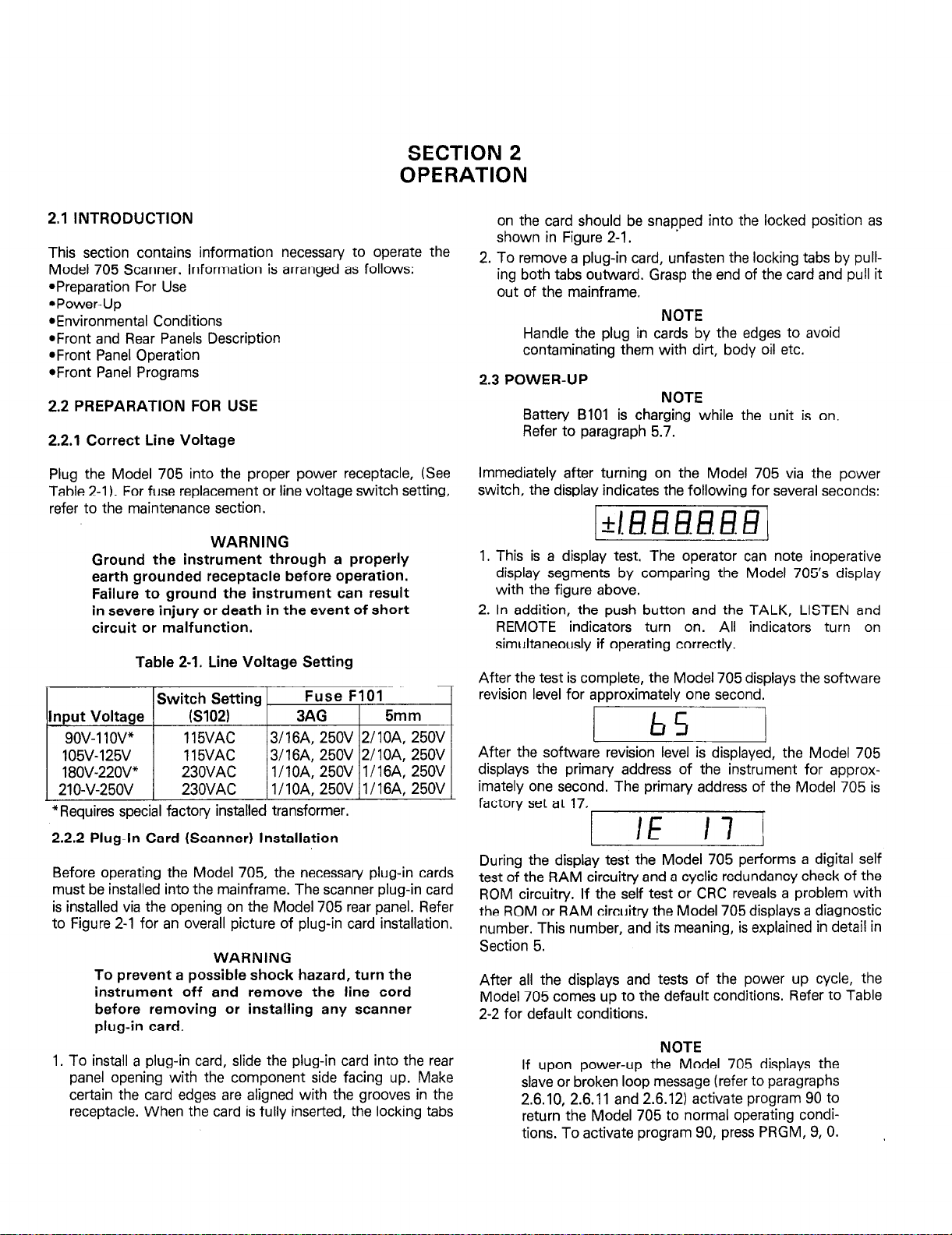
2.3 POWER-UP
Immediately after turning on the Model 705 via the power
switch, the display indicates the following for several seconds:
1. This is a display test. The operator can note inoperative
display segments by comparing the Model 705’s display
with the figure above.
2. In addition, the push button and the TALK, LISTEN and
REMOTE indicators turn on. All indicators turn on
simultaneously if operating correctly.
After the test is complete, the Model 705 displays the software
revision level for approximately one second.
card should be snapped into the locked position as
in Figure 2-1. .
NOTE
Handle the plug in cards by the edges to avoid
contaminating them with dirt, body oil etc.
NOTE
Batten/ BIOI is charging while the unit is on.
Refer to paragraph 5.7.
*Requires special factory installed transformer.
2.2.2 Plug-In Card (Scanner) Installation
Before operating the Model 705, the necessary plug-in cards
must be installed into the mainframe. The scanner plug-in card
is installed via the opening on the Model 705 rear panel. Refer
to Figure 2-l for an overall picture of plug-in card installation.
WARNING
To prevent a possible shock hazard, turn the
instrument off and remove the line cord
before removing or installing any scanner
plug-in card.
1. To install a plug-in card, slide the plug-in card into the rear
panel opening with the component side facing up. Make
certain the card edges are aligned with the grooves in the
receptacle. When the card is fully inserted, the locking tabs
After the software revision level is displayed, the Model 705
displays the primary address of the instrument for approximately one second. The primary address of the Model 705 is
factory set at 17.
During the display test the Model 705 performs a digital self
test of the RAM circuitry and a cyclic redundancy check of the
ROM circuitry. If the self test or CRC reveals a problem with
the ROM or RAM circuitry the Model 705 displays a diagnostic
number. This number, and its meaning, is explained in detail in
Section 5.
After all the displays and tests of the power up cycle, the
Model 705 comes up to the default conditions. Refer to Table
2-2 for default conditions.
NOTE
If upon power-up the Model 705 displays the
slave or broken loop message (refer to paragraphs
2.6.10, 2.6.11 and 2.6.12) activate program 90 to
return the Model 705 to normal operating condi-
tions. To activate program 90, press PRGM, 9, 0.
Page 13

-SCANNER CARD
INSTALLED
CARD-
SLOTS
r4x-SCANNER CARD
2-2
Figure 2-l. Scanner Card Installation
Page 14
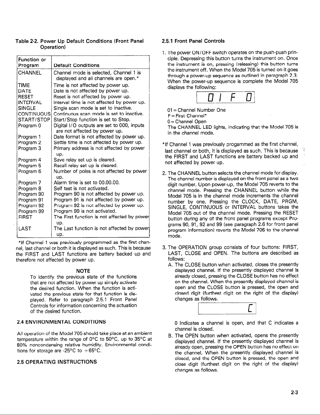
Table 2-2. Power Up Default Conditions (Front Panel
Operation)
Function or
Program Default Conditions
CHANNEL
TIME
DATE
RESET
INTERVAL
SINGLE
CONTINUOUS Continuous scan mode is set to inactive.
START/STOP Start/Stop function is set to Stop.
Program 0
Program 1
Program 2
Program 3
Program 4
Program 5
Program 6
Program 7
Program 8
Program 90
Program 91
Program 92
Program 99
FIRST
LAST
*If Channel 1 was previously programmed as the first channel, last channel or both it is displayed as such. This is because
the FIRST and LAST functions are battery backed up and
therefore not affected by power up.
To identify the previous state of the functions
that are not affected by power up simply activate
the desired function. When the function is activated the previous state for that function is dis-
played. Refer to paragraph 2.5.1 Front Panel
Controls for information concerning the actuation
of the desired function.
Channel mode is selected, Channel 1 is
displayed and all channels are open.*
Time is not affected by power up.
Date is not affected by power up.
Reset is not affected by power up.
Interval time is not affected by power up.
Single scan mode is set to inactive.
Digital I/O outputs are set to 000, inputs
are not affected by power up.
Date format is not affected by power up.
Settle time is not affected by power up.
Primary address is not affected by power
up.
Save relay set up is cleared.
Recall relay set up is cleared.
Number of poles is not affected by power
Ayirrn time is set to 00.00.00.
Self test is not activated.
Program 90 is not affected by power up.
Program 91 is not affected by power up.
Program 92 is not affected by power up.
Program 99 is not activated.
The First function is not affected by powe
up.
The Last function is not affected by powe
up*
NOTE
2.5.1 Front Panel Controls
1, The power ON/OFF switch operates on the push-push prin-
ciple. Depressing this button turns the instrument on. Once
the instrument is on, pressing (releasing) this button turns
the instrument off. When the Model 705 is turned on it goes
through a power-up sequence as outlined in paragraph 2.3.
When the power-up sequence is complete the Model 705
displays the following:
r D I F .a
I
01 = Channel Number One
F = First Channel*
0 = Channel Open
The CHANNEL LED lights, indicating that the Model 705 is
in the channel mode.
*If Channel 1 was previously progammed as the first channel,
last channel or both, it is displayed as such. This is because -li
the FIRST and LAST functions are battery backed up and
not affected by power up.
2. The CHANNEL button selects the channel mode for display.
The channel number is displayed on the front panel as a two
digit number. Upon power-up, the Model 705 reverts to the
channel mode. Pressing the CHANNEL button while the
Model 705 is in the channel mode increments the channel
number by one. Pressing the CLOCK, DATE, PRGM,
SINGLE, CONTINUOUS or INTERVAL buttons takes the
Model 705 out of the channel mode. Pressing the RESET
button during any of the front panel programs except Programs 90, 91, 92 and 99 (see paragraph 2.6 for front panel
program information) reverts the Model 705 to the channel
mode.
3. The OPERATION group consists of four buttons: FIRST,
LAST, CLOSE and OPEN. The buttons are described as
follows:
A. The CLOSE button when activated, closes the presently
displayed channel. If the presently displayed channel is
already closed, pressing the CLOSE button has no effect
on the channel. When the presently displayed channel is
open and the CLOSE button is pressed, the open and
closed digit (furthest digit on the right of the display)
changes as follows.
/
2.4 ENVIRONMENTAL CONDITIONS
All operation of the Model 705 should take place at an ambient
temperature within the range of O°C to 50°C, up to 35OC at
80% noncondensing relative humidity. Environmental conditions for storage are -25OC to + 65OC.
2.5 OPERATING INSTRUCTIONS
0 Indicates a channel is open, and that C indicates a
channel is closed.
B. The OPEN button when activated, opens the presently
displayed channel. If the presently displayed channel is
already open, pressing the OPEN button has no effect on
the channel. When the presently displayed channel is
closed, and the OPEN button is pressed, the open and
close digit (furthest digit on the right of the display)
changes as follows.
2-3
Page 15
L
I
C Indicates a closed channel, and that 0 indicates an
open channel.
NOTE
Close and open for each channel remain valid
even when not viewing the channel or the
display.
C. The FIRST button, when pressed, specifies the presently
displayed channel as the first channel of a multichannel
configuration. If the presently displayed channel has
already been specified as the first channel, pressing the
FIRST button has no effect on the channel or the
display. If the presently displayed channel has not been
specified as the first channel, the display format is shown
as follows:
11
01 = Present Channel
0 = Channel Open
Pressing the FIRST button specifies the channel as the
first channel and the display format is shown as follows:
1 UI f 3/
01 = Present Channel
F = First channel of a multichannel configuration
0 = Channel open
NOTE
There are two ways to change the specified first
channel, one is to select the desired new channel
and then press the FIRST button; the other way
is to activiate front panel Program 99 (refer to
paragraph 2.6). Powering the unit down will not
change the specified first channel.
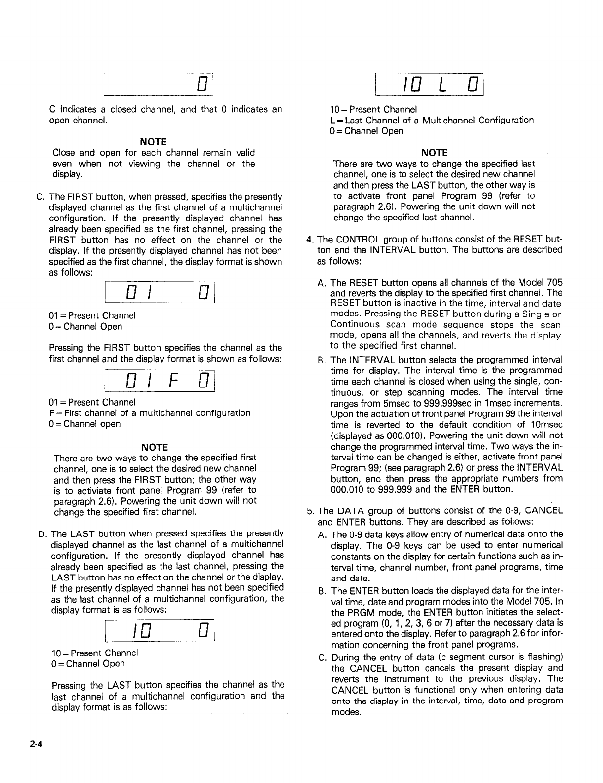
The LAST button when pressed specifies the presently
D.
displayed channel as the last channel of a multichannel
configuration. If the presently displayed channel has
already been specified as the last channel, pressing the
LAST button has no effect on the channel or the display.
If the presently displayed channel has not been specified
as the last channel of a multichannel configuration, the
display format is as follows:
I 113 ul
t
10 = Present Channel
0 = Channel Open
Pressing the LAST button specifies the channel as the
last channel of a multichannel configuration and the
display format is as follows:
I
10 = Present Channel
L= Last Channel of a Multichannel Configuration
0 = Channel Open
NOTE
There are two ways to change the specified last
channel, one is to select the desired new channel
and then press the LAST button, the other way is
to activate front panel Program 99 (refer to
paragraph 2.6). Powering the unit down will not
change the specified last channel.
4. The CONTROL group of buttons consist of the RESET button and the INTERVAL button. The buttons are described
as follows:
The RESET button opens all channels of the Model 705
A.
and reverts the display to the specified first channel. The
RESET button is inactive in the time, interval and date
modes. Pressing the RESET button during a Single or
Continuous scan mode sequence stops the scan
mode, opens all the channels, and reverts the display
to the specified first channel.
The INTERVAL button selects the programmed interval
B
time for display. The inten/al time is the programmed
time each channel is closed when using the single, con-
tinuous, or step scanning modes. The interval time
ranges from 5msec to 999.999sec in 1 msec increments.
Upon the actuation of front panel Program 99 the interval
time is reverted to the default condition of 10msec
(displayed as 000.010). Powering the unit down will not
change the programmed interval time. Two ways the in-
terval time can be changed is either, activate front panel
Program 99; (see paragraph 2.6) or press the INTERVAL
button, and then press the appropriate numbers from
000.010 to 999.999 and the ENTER button.
5. The DATA group of buttons consist of the O-9, CANCEL
and ENTER buttons. They are described as follows:
The O-9 data keys allow entry of numerical data onto the
A.
display. The O-9 keys can be used to enter numerical
constants on the display for certain functions such as interval time, channel number, front panel programs, time
and date.
The ENTER button loads the displayed data for the inter-
B.
val time, date and program modes into the Model 705. In
the PRGM mode, the ENTER button initiates the selected program (0, 1,2, 3, 6 or 7) after the necessary data is
entered onto the display. Refer to paragraph 2.6 for information concerning the front panel programs.
During the entry of data (c segment cursor is flashing)
C.
the CANCEL button cancels the present display and
reverts the instrument to the previous display. The
CANCEL button is functional only when entering data
onto the display in the interval, time, date and program
modes.
2-4
Page 16
6.
The SCAN group of buttons consists of the SINGLE, CONTINUOUS and START/STOP buttons. These three buttons
select the different scan modes. The SCAN group of buttons are described as follows:
A. The CONTINUOUS button selects the continuous scan
mode. The continuous scan mode allows the user to
scan through the programmed channels at the program-
med interval rate continuously. The continuous scan
mode is initiated upon the actuation of the
START/STOP button or upon receiving the appropriate
external trigger pulse. Pressing the START/STOP but-
ton while the continuous scan mode is running stops the
scan at the presently displayed channel. Pressing the
START/STOP button again starts the continuous scan
at the channel in which it was stopped.
B.
The SINGLE button selects the single scan mode. The
single scan mode allows the user to scan through the
programmed channels at the programmed interval rate
one time. The single scan mode is initiated upon the actuation of the START/STOP button or upon receiving
the appropriate external trigger pulse. Pressing the
START/STOP button while the single scan mode is running stops the scan at the presently displayed channel.
Unless interrupted, the single scan mode will scan
through the programmed channels at the programmed
interval rate and then stop at the programmed first channel.
C.
The START/STOP button is an alternate action control
that has three functions. The three functions are the
START function, the STOP function and the STEP scan
mode. They are described as follows:
a. The start function of the START/STOP button in-
itiates the selected scan mode. When all the parameters (interval, time, first and last channels, scan
mode, etc.) of a multichannel configuration have
been programmed and the user is ready to scan the
channels, press the START/STOP button to initiate
the scan. During the scan mode the START/STOP
LED is activated.
b. The stop function of the START/STOP button stops
the previously initiated scan mode. That is, pressing
the START/STOP button during a scan stops the
sequence at the presently displayed channel and turns
off the START/STOP LED. The stop function of the
START/STOP button is active only when a scanning
sequence is scanning.
c. The step scan mode allows the user to manually step
through the programmed channels. The step scan
mode is selected by pressing the channel button, programming the interval time and pressing the
START/STOP button. When the interval time has
been programmed and the user is ready to manually
scan the channels, press the START/STOP button to
scan (closed and open channel at the programmed interval time) one channel. Upon initiating the step scan
mode the START/STOP LED turns on, the presently
displayed channel is closed for the programmed interval rate, the channel is opened, the START/STOP
LED turns off and the Model 705 advances to the next
channel. To scan the next channel press the
START/STOP button and the Model 705 will go
through the same sequence.
7. The CLOCK group consists of two buttons that control the
display of the time function and the date function. The clock
continues to run after the instrument is powered down
because the clock’s power circuitn/ is backed up by battery
BTlOl. The two clock buttons are described as follows:
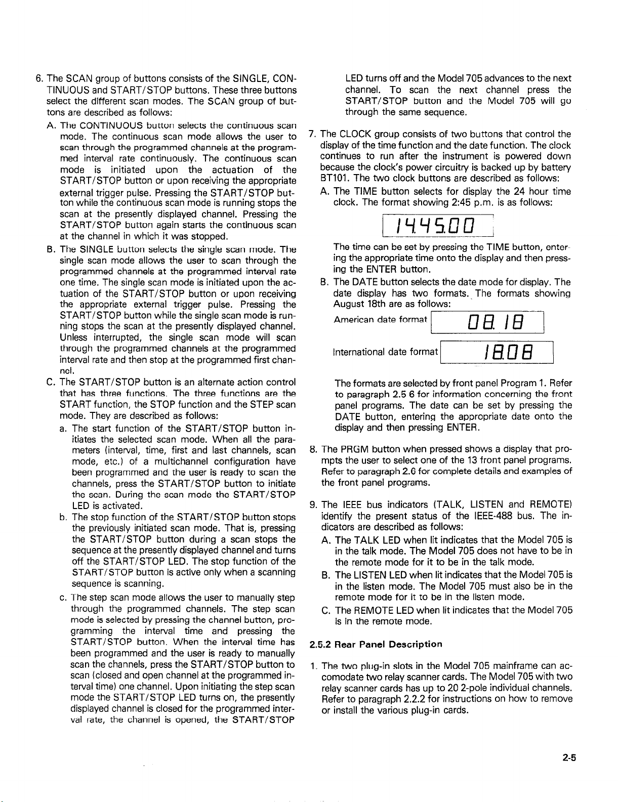
A. The TIME button selects for display the 24 hour time
clock. The format showing 2:45 p.m. is as follows:
I IYYS.UU /
i I
The time can be set by pressing the TIME button, entering the appropriate time onto the display and then pressing the ENTER button.
B. The DATE button selects the date mode for display. The
date display has two formats., The formats showing
Auaust 18th are as follows:
American date format
International date format
The formats are selected by front panel Program 1. Refer
to paragraph 2.5 6 for information concerning the front
panel programs. The date can be set by pressing the
DATE button, entering the appropriate date onto the
display and then pressing ENTER.
8. The PRGM button when pressed shows a display that prompts the user to select one of the 13 front panel programs.
Refer to paragraph 2.6 for complete details and examples of
the front panel programs.
9. The IEEE bus indicators (TALK, LISTEN and REMOTE)
identify the present status of the IEEE-488 bus. The in-
dicators are described as follows:
A. The TALK LED when lit indicates that the Model 705 is
in the talk mode. The Model 705 does not have to be in
the remote mode for it to be in the talk mode.
B. The LISTEN LED when lit indicates that the Model 705 is
in the listen mode. The Model 705 must also be in the
remote mode for it to be in the listen mode.
C. The REMOTE LED when lit indicates that the Model 705
is in the remote mode.
2.5.2 Rear Panel Description
1. The two plug-in slots in the Model 705 mainframe can accomodate two relay scanner cards. The Model 705 with two
relay scanner cards has up to 20 2-pole individual channels.
Refer to paragraph 2.2.2 for instructions on how to remove
or install the various plug-in cards.
cl0 I8
I I
Ifm3 I
2-5
Page 17
fi?ciEq
705 SCANNER
\ 4
OPERATION
DATA
7 8
9
q ncl
POWER
a ON
1 OFF
i
n
v
0
RESET
sl fl
L&l
INTERVAL CONTINUOUS
/\
SCAN
.
PRGM
4
q
IC
SERIAL
hxl
0 CANCEL ENTER
non
DIGITAL I/O
OUT SERIAL IN
ALARM /
I
@-/-@I
30V ‘MAX.
h
2-6
f~.:,~~;:G;O
m<~t~~cncoaouL
L
IEEE 488 INTERFACE
I
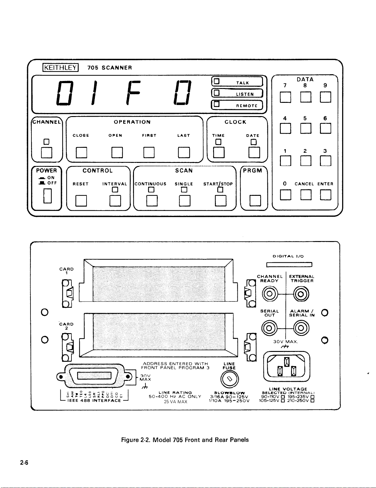
Figure 2-2. Model 705 Front and Rear Panels
LINE RATING
50-400 Hz AC ONLY
25 VA MAX
LINE
FUSE
SLOWSLOW
3ll6A 90- 125V
l/lOA 195-250V
LINE VOLTAGE
SELECTED (INTERNAL)
go-1lOV 0 195-235v a
105-125V 0 210-250V 0
Page 18
2. The EXTERNAL TRIGGER is a BNC connector that initiates
the selected scan mode (single, step or continuous) in the
same manner as the START/STOP button, The input trigger pulse must be a negative going pulse at a TTL level with
a minimum duration of 2+ec. The selected program mode
is initiated upon the negative transition of the pulse. This
feature can be used to trigger the Model 705 into the
selected scan mode using another instrument.
3. CHANNEL READY is a BNC output connector that provides
a negative going TTL level pulse of greater than lO@ec at
the completion of the programmed channel settling time.
This feature can be used to inform another instrument (e.g.
DMM, Source, etc,) that the present channel settling time is
completed.
4. The ALARM/SERIAL IN connector has two functions. The
Alarm out function and the SERIAL IN function. As the
Alarm out function the Model 705 outputs a negative going
TTL level greater than 10pec pulse to the ALARM/SERIAL
IN connector. When the Alarm time is set to 00.00.00 the
pulse does not appear. The SERIAL IN function is used in a
daisy chain configuration where the SERIAL IN connector is
connected to the SERIAL OUT connector of another Model
705. Refer to paragraph 2.5.3 example 4 for more information.
5. SERIAL OUT is a BNC output connector that provides connection to another Model 705 for a daisy chain configura-
tion. Refer to Figure 2-3 for a typical daisy chain configuration. The SERIAL OUT connector is applied to the
ALARM/SERIAL IN connector of another Model 705.
6. The Digital I/O port consists of 16 digital input/output lines
along with four lines that are + 5V and IEEE common. Eight
of the I/O lines can be used for inputs and eight can be used
for outputs. This allows the user a limited number of control
lines to the IEEE bus. The outputs will drive one TTL load
and the inputs are TTL compatible. For more information
concerning the digital I/O port refer to paragraph 3.5.8/16.
7. The IEEE bus connector provides bus connection to the
Model 705. The connector mates with the Keithley Model
7008-3 and Model 7008-6 cables. For more detailed infor-
mation concerning the IEEE connector refer to paragraph
3.3.
8. The line power fuse is rated as specified in Table 5-l.
9. The line power receptacle mates with three wire line cord
which provides connections to line voltage. For correct line
voltage selection refer to paragraph 5.3.
2.5.3 Basic Front Panel Operation
This section provides the information necessary for basic front
panel operation of the Model 705. There are a number of steps
to follow in order to get the Model 705 ready for scanning
operation. These steps are as follows:
1. Install the desired scanner card(s). Refer to paragraph 2.2.2
for information concerning the installation of the scanner
cards into the Model 705.
2. Select appropriate line voltage. Refer to paragraph 2.2.1 for
information concerning the selection of the appropriate line
voltage. Turn the Model 705 on. The instrument goes
through the power-up sequence described in paragraph 2.3
and displays the following:
I III f o!
NOTE
Channel 1 is set as the programmed first channel,
unless the unit was previously programmed for
another channel then that channel is displayed.
3. Program the desired channel.
A. Select the first channel.
a. Press the desired channel number from the DATA
group buttons O-9.
b. Press the FIRST button to program the present chan-
nel as the first channel.
NOTE
Selecting a channel that does not exist in the present set up causes the Model 705 to display the
following message.
/-Ia
9. Select the last channel:
a. Press the desired number from the DATA group but-
tons O-9.
b. Press the LAST button to program the present chan-
nel as the last channel.
4. Program the desired number of poles (I-, 2- or 4-pole).
A. Press PRGM.
9. Press 6 (refer to paragraph 2.6.7).
C. Select number of poles l-, 2- or 4-pole.
D. Press ENTER.
5. Program the interval time
A. Press the INTERVAL button to select the interval mode
for display.
9. Enter the interval time on the display by pressing from
the DATA group, desired time 000.010 to 999.999
seconds.
C. Press the ENTER button.
6. Program the desired scan mode. Press the SINGLE or CONTINUOUS button to select one of these two scanning
modes. To select the step scan mode press the channel but-
ton and the START/STOP button.
7. Press the START/STOP button to start the scanning
sequence. For the step scan mode press the START/STOP
button each time a single channel is to be scanned.
l-h
2-7
Page 19
Steps 1 through 7 show how to get the Model 705 into a
scanning sequence. The next examples show how to use
the different scan modes, how to daisy chain several Model
705’s for an extended number of channels, and scanning
using different scanner cards,
Example 1 Manual Scan-The Model 705 can be programmed for the step scan mode, if it is desired to scan through the
programmed channels manually. In the step scan mode the
programmed channels can be scanned (closed for the programmed interval rate and then opened) one channel at a time.
Upon the actuation of the START/STOP button a single channel will be scanned. For this example, choose the following
parameters:
1. First channel is 1.
2. Last channel is 10.
3. Interval time is two seconds.
4. Number of poles is two.
5. Use the step scan mode.
Use the following procedure to program the Model 705 for the
preceding parameters:
1. Install the desired scanner card into the Model 705. Refer to
paragraph 2.2.2.
2. Select the appropriate line voltage and turn the Model 705
on. Refer to paragraphs 2.2.1 and 2.3 respectively.
3. Press PRGM, 6, 2, ENTER. For more complete information
refer to paragraph 2.6.7.
4. Press 0, 1, FIRST. (Programs channel 1 as the first channel.)
5. Press 1, 0, LAST. (Programs channel 10 as the last
channel.)
6. Press INTERVAL, 0, 0, 2, 0, 0, 0, ENTER. (Programs the interval time for two seconds.)
7. Press CHANNEL, RESET. (Selects the channel mode for
display and resets to the first channel.)
8. Press the START/STOP button to initiate the step scan
mode.
Upon the actuation of the START/STOP button in step 8,
channel 1 is closed and the START/STOP LED is turned on.
Channel 1 remains closed for two seconds (programmed interval rate) and then opens, The START/STOP LED turns off
and the Model 705 advances to the next channel. To scan the
remaining channels press START/STOP button each time a
channel is to be scanned. When the last programmed channel
is scanned, in this example, it goes through the same procedure as previously stated. The difference is that after the
channel opens up and turns off the START/STOP LED, the
Model 705 resets to the first programmed channel.
grammed last channel, at this point the Model 705 reverts to
the programmed first channel and stops. Upon the actuation
of the START/STOP button all the programmed channels are
scanned at the programmed interval rate. For this example let
us choose the following parameters:
1. First channel is 3.
2. Last channel is 15.
3. Interval time is 0.5 seconds.
4. Number of poles is 2.
5. Use the single scan mode.
Use the following procedure to program the Model 705 for the
preceding parameters:
1. Install the desired scanner card into the Model 705. Refer to
paragraph 2.2.2
2. Select appropriate line voltage and turn the Model 705 on.
Refer to paragraphs 2.2.1 and 2.3 respectively.
3. Press PRGM, 6, 2, ENTER. For more complete details refer
to paragraph 2.6.7.
4. Press 0, 3, FIRST. (Programs channel 3 as the first channel.)
5. Press 1, 5, LAST. (Programs channel 15 as the last
channel.)
6. Press INTERVAL, 0, 0, 0, 5, 0, 0, ENTER (Programs the interval time for 0.5 seconds.)
7. Press CHANNEL, RESET. (Turns on the CHANNEL LED,
selects the channel mode for display and resets to the pro-
grammed first channel.)
8. Press SINGLE. (Selects the single scan mode and turns on
the SINGLE LED.)
9. Press the START/STOP button to inititate the single scan
mode.
Upon the actuation of the START/STOP button in step 9,
channel 3 is closed for 0.5 seconds (programmed interval rate
and the START/STOP LED turns on). Channel 3 is opened
and the Model 705 advances to the next channel. Channel 4 is
closed for 0.5 seconds and then opens. The Model 705 then
advances to channel 5 and the cycle repeats itself until the last
channel is scanned (closed for the programmed interval rate
and then opened). At the end of the scan of the last channel,
the Model 705 resets to the programmed first channel and
turns off the START/STOP LED. At this point the single mode
has been completed.
Pressing the START/STOP button during a single scan stops
the scan at the presently displayed channel. The channel remains closed and turns off the START/STOP LED. To start
the scanning sequence from the presently displayed channel
press the START/STOP button.
To stop the scanning sequence and reset the Model 705 to the
programmed first channel simply press the RESET button.
Example 2 Single Scan-In the Single Scan mode all the
channels are scanned one time. The Scan runs as follows: the
first channel is closed for the programmed interval rate and
then opened. The Model 705 advances to the next channel,
closes it for the programmed interval rate and then opens the
channel. The sequence is repeated up to and including the pro-
2-8
To stop the scanning sequence and reset the Model 705 to the
programmed first channel simply press the RESET button.
Example 3 Continuous Scan-In the Continuous scan mode
all the programmed channels are scanned continuously. The
scan runs as follows: the first channel is closed for the programmed interval rate and then opened. The Model 705 then
advances to the next channel, closes it for the programmed interval rate and then opens the channel. The sequence is
Page 20
repeated until the START/STOP button is pressed. Upon actuation of the START/STOP button all the programmed channels are scanned continuously at the programmed interval rate.
For this example choose the following parameters:
1. First channel is 5.
2. Last channel is 20.
3. Interval time is one second.
4. Number of poles is 2.
5. Use continuous scan mode.
Use the following procedure to program the Model 705 for the
preceding parameters:
I, Install the desired scanner card into the Model 705. Refer to
paragraph 2.2.2.
2. Select appropriate line voltage and turn the Model 705 on.
Refer to paragraphs 2.2.1 and 2.3 respectively.
3. Press PRGM, 6, 2, ENTER. For more complete details refer
to paragraph 2.6.7.
4. Press 0, 5, FIRST. (Programs channel 5 as the first channel.)
5. Press 2, 0, LAST. (Programs channel 20 as the last
channel.)
6. Press INTERVAL, 0, 0, 1, 0, 0, 0, ENTER. (Programs the in-
terval time for one second.)
7. Press CHANNEL, RESET. (Turns on the channel LED,
selects the channel mode for display and resets to the pro-
grammed first channel.)
8. Press CONTINUOUS. (Selects the continuous scan mode
and turns on the continuous LED.)
9. Press the START/STOP button to initiate the continuous
scan mode.
Upon the actuation of the START/STOP button in step 9,
channel 5 is closed for one second (programmed interval rate)
and the START/STOP LED turns on. Channel 5 is then opened and the Model 705 advances to the next channel. Channel 6
closes for one second and then opens. The Model 705 advances to the next channel and the cycle repeats itself until the
last channel is scanned (closed for the programmed interval
rate and then opened). At the end of the scan of the last chan-
nel, the Model 705 resets to the programmed first channel and
then repeats the scanning sequence.
The scanning sequence can be stopped at any programmed
channel by simply pressing the START/STOP button. Press-
ing the START/STOP button during a continuous scan stops
the scan at the presently displayed channel, the channel re-
mains closed, and turns off the START/STOP LED. To start
the scanning sequence from the presently displayed channel
press the START/STOP button, After the scanning sequence
has stopped, pressing the START/STOP button starts the
sequence from the presently displayed channel and turns on
the START/STOP LED.
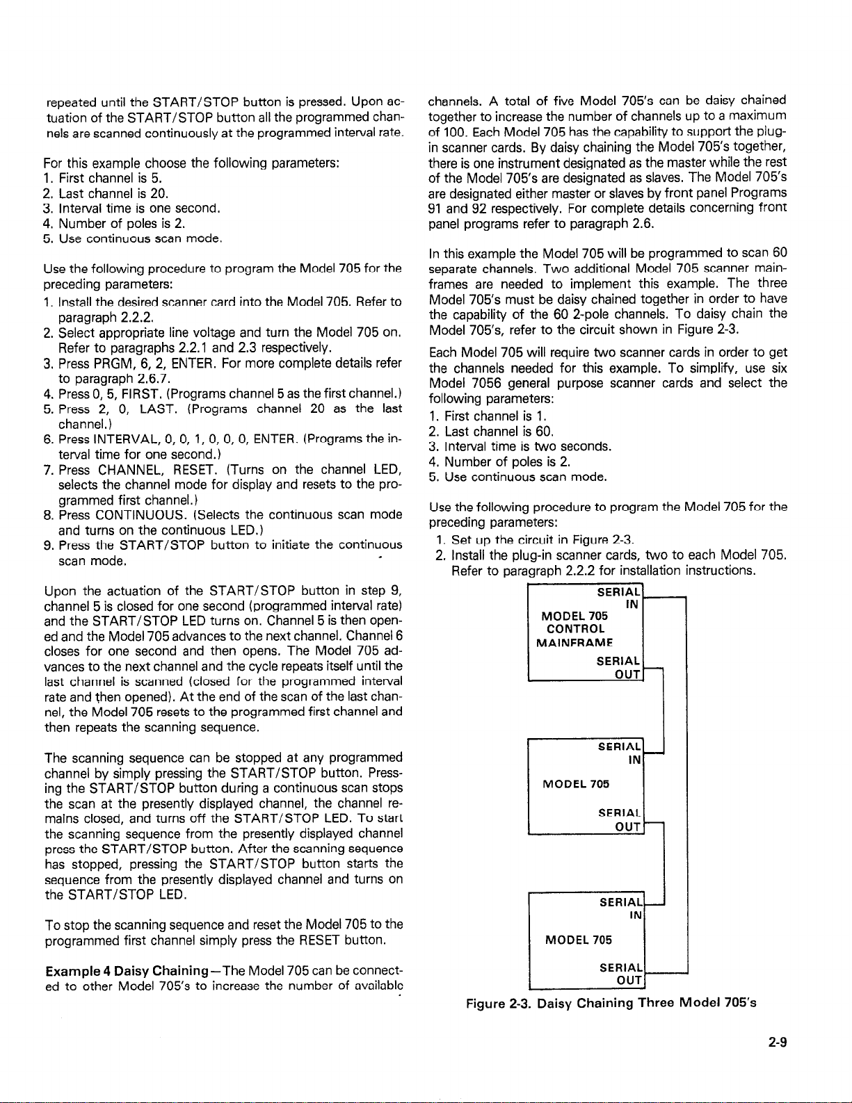
channels. A total of five Model 705’s can be daisy chained
together to increase the number of channels up to a maximum
of 100. Each Model 705 has the capability to support the plugin scanner cards. By daisy chaining the Model 705’s together,
there is one instrument designated as the master while the rest
of the Model 705’s are designated as slaves. The Model 705’s
are designated either master or slaves by front panel Programs
91 and 92 respectively. For complete details concerning front
panel programs refer to paragraph 2.6.
In this example the Model 705 will be programmed to scan 60
separate channels, Two additional Model 705 scanner mainframes are needed to implement this example. The three
Model 705’s must be daisy chained together in order to have
the capability of the 60 2-pole channels. To daisy chain the
Model 705’s, refer to the circuit shown in Figure 2-3.
Each Model 705 will require two scanner cards in order to get
the channels needed for this example. To simplify, use six
Model 7056 general purpose scanner cards and select the
following parameters:
1. First channel is 1.
2. Last channel is 60.
3. Interval time is two seconds.
4. Number of poles is 2.
5. Use continuous scan mode.
Use the following procedure to program the Model 705 for the
preceding parameters:
1. Set up the circuit in Figure 2-3.
2. Install the plug-in scanner cards, two to each Model 705.
Refer to paragraph 2.2.2 for installation instructions.
MODEL 705
CONTROL
MAINFRAME
SERIAL
IN
MODEL 705
r-r
To stop the scanning sequence and reset the Model 705 to the
programmed first channel simply press the RESET button.
Example 4 Daisy Chaining-The Model 705 can be connect-
ed to other Model 705’s to increase the number of available
Figure 2-3. Daisy Chaining Three Model 705’s
2-9
Page 21
3. Select appropriate line voltage and turn the Model 705’s
on. Refer to paragraphs 2.2.1 and 2.3 respectively.
4. Press PRGM, 6, 2, ENTER. For complete details refer to
paragraph 2.6.7.
5. Program one Model 705 as the master by initiating front
panel Program 91. For complete details concerning the
front panel programs refer to paragraph 2.6.
6. Program remaining Model 705’s as slaves by initiating front
panel Program, 92 for each of the remaining Model 705’s.
To do this press PRGM button and then press 9, 2.
All remaining Model 705’s will have to be programmed in
the same way. For complete details concerning the front
panel programs refer to paragraph 2.6.
NOTE
Initiating front panel Program 92 locks up the
Model 705 front panel except for program 90 and
91 which allow you to go to stand alone or
master. The following message is displayed while
the front panel is locked up.
I i;Lf?UE I
I
7. Press 0, 1, FIRST. (Programs channel 1 as the first channel.)
8. Press 6, 0, LAST. (Programs channel 60 as the last channel.)
NOTE
If the Model 705’s are not daisy chained together,
pressing 6, 0 in step 8 causes the Model 705 to
display the following message for approximately
0.5 seconds.
-1
The display message indicates that there is no
channel 60.
9. Press INTERVAL, 0, 0, 2, 0, 0, 0, ENTER. (Programs the
interval time for two seconds.)
10. Press CHANNEL, RESET. (Turns on the channel LED,
selects the channel mode for display and resets the Model
705 to the programmed first channel.)
11. Press CONTINUOUS. (Selects the continuous scan mode
and turns on the continuous LED.)
12. Press the START/STOP button to initiate the continuous
scan mode.
Upon the actuation of the START/STOP button in step 12,
the continuous scan sequence starts from the programmed
first channel. The continuous scan mode operates in the same
way as in Example 3. That is, the first channel is closed for the
programmed interval time and the START/STOP LED is turned on; then the channel is opened, and the Model 705 advances to the next channel. This sequence is repeated up to
the last channel and then instead of advancing to the next
channel the Model 705 resets to the programmed first channel
and the entire sequence is repeated.
I
The scanning sequence can be stopped at any programmed
channel by simply pressing the START/STOP button. Pressing the START/STOP button during a continuous scan stops
the scan at the presently displayed channel, the channel remains closed, and turns off the START/STOP LED. To start
the scanning sequence from the presently displayed channel,
press the START/STOP button. The START/STOP LED
turns on when resuming the scan,
To stop the scanning sequence, and reset the Model 705 to
the programmed first channel,simply press the RESET button.
Example 5 Temperature Scan-With the Model 7057 thermocouple plug in card, the Model 705 can scan separate temperature points. The Model 7057 thermocouple scanner card is
field installable in the Model 705 Scanner mainframe. Since the
Model 7057 combines the functions of a thermocouple scanner and uniform temperature reference it is especially useful for
scanning thermocouples. The input terminals are #lO alloycopper set in an isothermal block to minimize temperature dif-
ferences. A thermistor sensor within the isothermal block is
used with a bridge network located on the Model 7057 to give
an indication of the temperature reference or cold junction.
The temperature of the heat sink is used to calculate the cor-
rected thermocouple output. The output voltages of each thermocouple must be converted to temperature (OC or OF) using
appropriate thermocouple tables or polynomial equations. In-
put and output connections are made through the rear panel of
the Model 705 Scanner mainframe using #4 screw terminals on
the Model 7057. For complete details concerning the Model
7057 thermocouple scanner card refer to the Model 7057 Instruction Manual.
In this example, the Model 705 will be programmed to scan
five separate temperatures. Also, the following parameters will
be programmed into the Model 705.
I. First channel is 1.
2. Last channel is 6.
3. Number of poles is 2.
4. Interval time is three seconds,
5. Use the continuous scan mode.
Use the following procedure to program the Model 705 for this
example:
1. If Example 4 is still set up, disconnect it. Connect the five
temperature sources to the Model 7057 via the #4 screw
terminals at the rear of the card.
2. Install the Model 7057 into the Model 705 Scanner mainframe. Refer to paragraph 2.2.2 for scanner card installation instructions.
3. Select appropriate line voltage and turn on the Model 705.
Refer to paragraphs 2.2.1 and 2.3 respectively.
4. Press PRGM, 6, 2, ENTER. For complete details concerning front panel programs refer to paragraph 2.6.
5. Press 0, 1, FIRST. (Programs channel 1 as the first channel.) Channel 1 is used to monitor the temperature of the
input terminals with the thermistor bridge.
6. Press 0, 6, LAST, (Programs channel 6 as the last
channel.)
2-10
Page 22
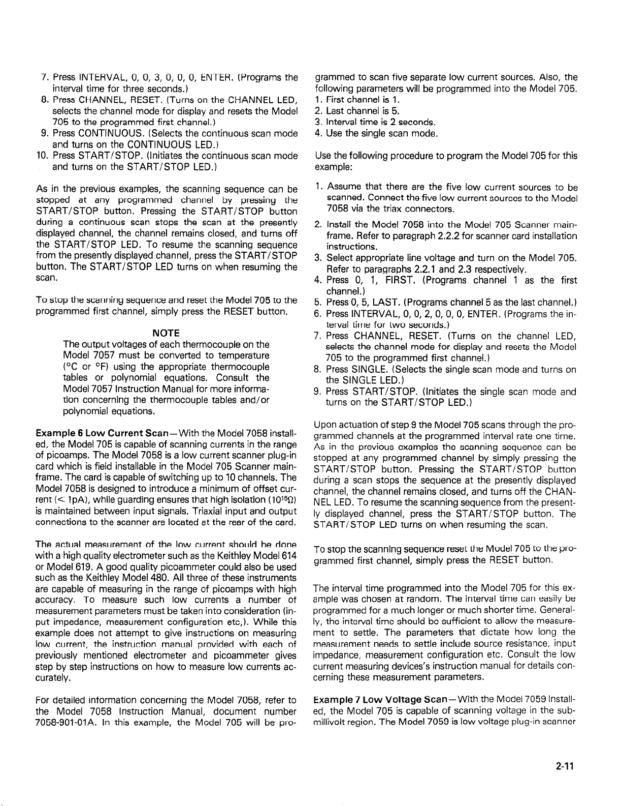
7. Press INTERVAL, 0, 0, 3, 0, 0, 0, ENTER. (Programs the
interval time for three seconds.)
8. Press CHANNEL, RESET. (Turns on the CHANNEL LED,
selects the channel mode for display and resets the Model
705 to the programmed first channel.)
9. Press CONTINUOUS. (Selects the continuous scan mode
and turns on the CONTINUOUS LED.)
10. Press START/STOP. (Initiates the continuous scan mode
and turns on the START/STOP LED.)
As in the previous examples, the scanning sequence can be
stopped at any programmed channel by pressing the
START/STOP button. Pressing the START/STOP button
during a continuous scan stops the scan at the presently
displayed channel, the channel remains closed, and turns off
the START/STOP LED. To resume the scanning sequence
from the presently displayed channel, press the START/STOP
button. The START/STOP LED turns on when resuming the
scan.
To stop the scanning sequence and reset the Model 705 to the
programmed first channel, simply press the RESET button.
NOTE
The output voltages of each thermocouple on the
Model 7057 must be converted to temperature
(OC or OF) using the appropriate thermocouple
tables or polynomial equations, Consult the
Model 7057 Instruction Manual for more informa-
tion concerning the thermocouple tables and/or
polynomial equations,
Example 6 Low Current Scan-With the Model 7058 installed, the Model 705 is capable of scanning currents in the range
of picoamps. The Model 7058 is a low current scanner plug-in
card which is field installable in the Model 705 Scanner mainframe. The card is capable of switching up to 10 channels. The
Model 7058 is designed to introduce a minimum of offset current (< IpA), while guarding ensures that high isolation (101%)
is maintained between input signals. Triaxial input and output
connections to the scanner are located at the rear of the card.
grammed to scan five separate low current sources. Also, the
following parameters will be programmed into the Model 705.
1. First channel is 1.
2. Last channel is 5.
3. Interval time is 2 seconds.
4. Use the single scan mode.
Use the following procedure to program the Model 705 for this
example:
1.
Assume that there are the five low current sources to be
scanned. Connect the five low current sources to the Model
7058 via the triax connectors.
2. Install the Model 7058 into the Model 705 Scanner mainframe. Refer to paragraph 2.2.2 for scanner card installation
instructions.
3.
Select appropriate line voltage and turn on the Model 705.
Refer to paragraphs 2.2.1 and 2.3 respectively.
4.
Press 0, 1, FIRST. (Programs channel 1 as the first
channel. 1
5.
Press 0, 5, LAST. (Programs channel 5 as the last channel.)
6.
Press INTERVAL, 0, 0, 2, 0, 0, 0, ENTER. (Programs the interval time for two seconds.)
7.
Press CHANNEL, RESET. (Turns on the channel LED,
selects the channel mode for display and resets the Model
705 to the programmed first channel.)
8.
Press SINGLE. (Selects the single scan mode and turns on
the SINGLE LED.)
9.
Press START/STOP. (Initiates the single scan mode and
turns on the START/STOP LED.)
Upon actuation of step 9 the Model 705 scans through the programmed channels at the programmed interval rate one time.
As in the previous examples the scanning sequence can be
stopped at any programmed channel by simply pressing the
START/STOP button. Pressing the START/STOP button
during a scan stops the sequence at the presently displayed
channel, the channel remains closed, and turns off the CHANNEL LED. To resume the scanning sequence from the presently displayed channel, press the START/STOP button. The
START/STOP LED turns on when resuming the scan.
The actual measurement of the low current should be done
with a high quality electrometer such as the Keithley Model 614
or Model 619. A good quality picoammeter could also be used
such as the Keithley Model 480. All three of these instruments
are capable of measuring in the range of picoamps with high
accuracy. To measure such low currents a number of
measurement parameters must be taken into consideration (input impedance, measurement configuration etc,). While this
example does not attempt to give instructions on measuring
low current, the instruction manual provided with each of
previously mentioned electrometer and picoammeter gives
step by step instructions on how to measure low currents accurately.
For detailed information concerning the Model 7058, refer to
the Model 7058 Instruction Manual, document number
7058-901-OIA. In this example, the Model 705 will be pro-
To stop the scanning sequence reset the Model 705 to the pro-
grammed first channel, simply press the RESET button.
The interval time programmed into the Model 705 for this example was chosen at random. The interval time can easily be
programmed for a much longer or much shorter time. Generally, the interval time should be sufficient to allow the measurement to settle. The parameters that dictate how long the
measurement needs to settle include source resistance, input
impedance, measurement configuration etc. Consult the low
current measuring devices’s instruction manual for details concerning these measurement parameters.
Example 7 Low Voltage Scan-With the Model 7059 installed, the Model 705 is capable of scanning voltage in the submillivolt region. The Model 7059 is low voltage plug-in scanner
2-l 1
Page 23
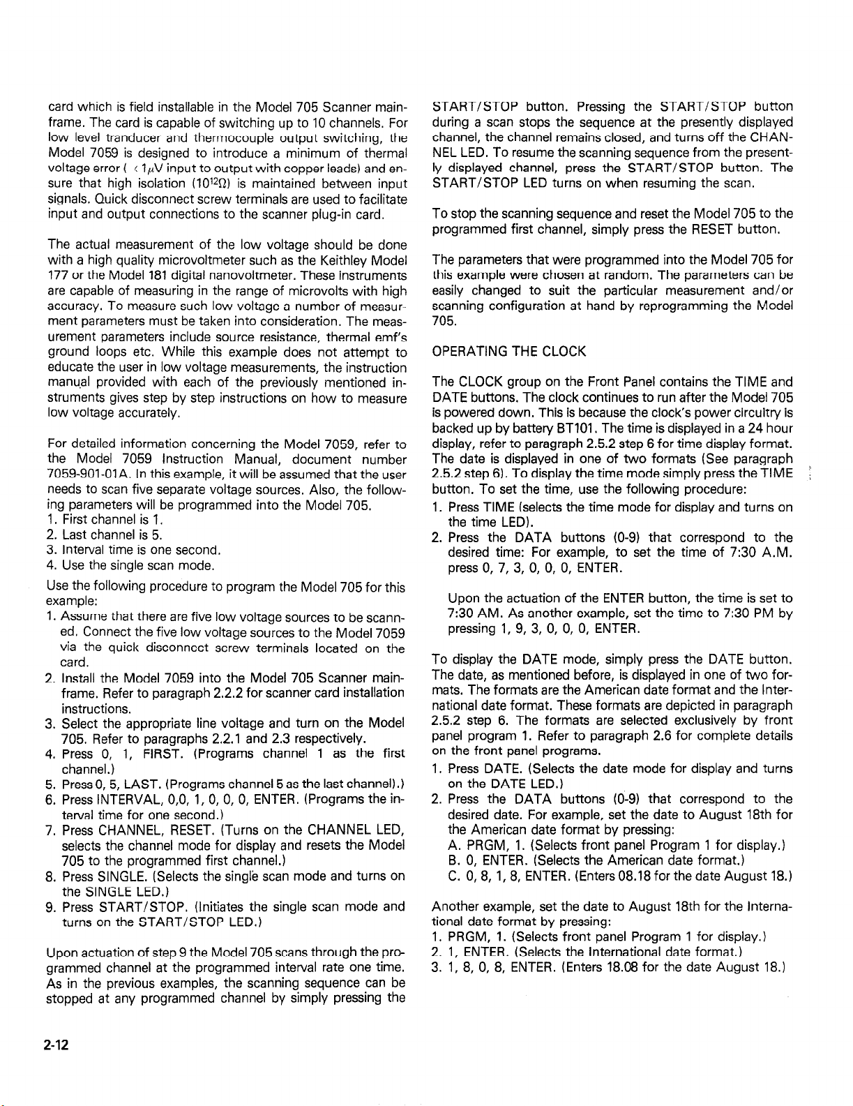
card which is field installable in the Model 705 Scanner mainframe. The card is capable of switching up to 10 channels. For
low level tranducer and thermocouple output switching, the
Model 7059 is designed to introduce a minimum of thermal
voltage error ( ( IpV input to output with copper leads) and ensure that high isolation (lOl*D) is maintained between input
signals. Quick disconnect screw terminals are used to facilitate
input and output connections to the scanner plug-in card.
The actual measurement of the low voltage should be done
with a high quality microvoltmeter such as the Keithley Model
177 or the Model 181 digital nanovoltmeter. These instruments
are capable of measuring in the range of microvolts with high
accuracy. To measure such low voltage a number of measur-
ment parameters must be taken into consideration. The meas-
urement parameters include source resistance, thermal emf’s
ground loops etc. While this example does not attempt to
educate the user in low voltage measurements, the instruction
manual provided with each of the previously mentioned instruments gives step by step instructions on how to measure
low voltage accurately.
For detailed information concerning the Model 7059, refer to
the Model 7059 Instruction Manual, document number
7059-901-Ol A. In this example, it will be assumed that the user
needs to scan five separate voltage sources, Also, the following parameters will be programmed into the Model 705.
1. First channel is 1.
2. Last channel is 5.
3. Interval time is one second.
4. Use the single scan mode.
Use the following procedure to program the Model 705 for this
example:
1. Assume that there are five low voltage sources to be scann-
ed. Connect the five low voltage sources to the Model 7059
via the quick disconnect screw terminals located on the
card.
2. Install the Model 7059 into the Model 705 Scanner mainframe. Refer to paragraph 2.2.2 for scanner card installation
instructions.
3. Select the appropriate line voltage and turn on the Model
705. Refer to paragraphs 2.2.1 and 2.3 respectively.
4. Press 0, 1, FIRST. (Programs channel 1 as the first
channel.)
5. Press 0, 5, LAST. (Programs channel 5 as the last channel).)
6. Press INTERVAL, O,O, 1, 0, 0, 0, ENTER. (Programs the in-
terval time for one second.)
7. Press CHANNEL, RESET. (Turns on the CHANNEL LED,
selects the channel mode for display and resets the Model
705 to the programmed first channel.)
8. Press SINGLE. (Selects the singl’e scan mode and turns on
the SINGLE LED.)
9. Press START/STOP. (Initiates the single scan mode and
turns on the START/STOP LED.)
Upon actuation of step 9 the Model 705 scans through the pro-
grammed channel at the programmed interval rate one time.
As in the previous examples, the scanning sequence can be
stopped at any programmed channel by simply pressing the
START/STOP button. Pressing the START/STOP button
during a scan stops the sequence at the presently displayed
channel, the channel remains closed, and turns off the CHANNEL LED. To resume the scanning sequence from the presently displayed channel, press the START/STOP button. The
START/STOP LED turns on when resuming the scan.
To stop the scanning sequence and reset the Model 705 to the
programmed first channel, simply press the RESET button.
The parameters that were programmed into the Model 705 for
this example were chosen at random. The parameters can be
easily changed to suit the particular measurement and/or
scanning configuration at hand by reprogramming the Model
705.
OPERATING THE CLOCK
The CLOCK group on the Front Panel contains the TIME and
DATE buttons. The clock continues to run after the Model 705
is powered down. This is because the clock’s power circuitry is
backed up by battery BTlOl . The time is displayed in a 24 hour
display, refer to paragraph 2.5.2 step 6 for time display format.
The date is displayed in one of two formats (See paragraph
2.5.2 step 6). To display the time mode simply press the TIME
button. To set the time, use the following procedure:
1. Press TIME (selects the time mode for display and turns on
the time LED).
2. Press the DATA buttons (O-9) that correspond to the
desired time: For example, to set the time of 7:30 A.M.
press 0, 7, 3, 0, 0, 0, ENTER.
Upon the actuation of the ENTER button, the time is set to
7:30 AM. As another example, set the time to 7:30 PM by
pressing 1, 9, 3, 0, 0, 0, ENTER.
To display the DATE mode, simply press the DATE button.
The date, as mentioned before, is displayed in one of two formats. The formats are the American date format and the International date format. These formats are depicted in paragraph
2.5.2 step 6. The formats are selected exclusively by front
panel program 1. Refer to paragraph 2.6 for complete details
on the front panel programs.
1. Press DATE. (Selects the date mode for display and turns
on the DATE LED.)
2. Press the DATA buttons (O-9) that correspond to the
desired date. For example, set the date to August 18th for
the American date format by pressing:
A. PRGM, 1. (Selects front panel Program 1 for display.)
9. 0, ENTER. (Selects the American date format.)
C. 0, 8, 1,8, ENTER. (Enters 08.18 for the date August 18.)
Another example, set the date to August 18th for the International date format by pressing:
1. PRGM, 1. (Selects front panel Program 1 for display.)
2. 1, ENTER. (Selects the International date format.)
3. 1, 8, 0, 8, ENTER. (Enters 18.08 for the date August 18.)
2-12
Page 24

2.6 FRONT PANEL PROGRAMS
This section contains instructions necessary for operating the
13 internal programs of the Model 705. The programs are ac-
tivated by pressing the PRGM button along with the button
representing the appropriate program number. The programs
do a number of various tasks which are summarized in Table
2-3.
8. If too many digits are entered, the display begins again at
the first digit on the left, All the digits in the constant must
then be entered again. This applies only to Programs 0,2,3,
6 and 7.
9. Once all the digits of the desired constants are shown on the
display, the constant is entered into the program by pressing
the ENTER button. This applies only to Programs 0, 1, 2, 3,
4, 5, 6 and 7.
Program Notes
1. Each program is entered by pressing the PRGM button
followed by the desired program number.
2. Pressing the PRGM button selects the program mode and
displays the following:
j
As you have noticed, the question mark is flashing. This is
prompting the operator to enter the desired program
number (refer to Table 2-3). After entering the program
number the Model 705 goes into the program and then prompts the operator to enter numerical data. Numerical data
varies with each program.
3. New programs may be entered without clearing a program
that is presently running. To do so, press the PRGM button
followed by the desired program number.
4. Data is entered into the digit whose “c” segment is flashing
by pressing the desired number button. The “c” segment of
a display digit is shown below:
I3
w’c” segment
As each digit is entered, the blinking segment moves one
place to the right until all the necessary digits have been
entered.
5. Only as many significant digits as necessary need to be
entered. The Model 705 will complete the constants with
trailing zeroes where necessary.
6. Invalid keys will be ignored. If an invalid key is pressed the
blinking “c” segment remains at the current digit.
7. If an incorrect digit is entered, the complete constant must
be re-entered. The new value may be entered by cycling the
display around to the beginning by repeatedly pressing one
of the number buttons.
Table 2-3. Summary of Front Panel Programs
Vogram Operation
0 Digital I/O (Input/Output)
1
2 Settling Time
3 Set Primary Address
4
5 Recall Stored Relay Set Up
6 Pole Configuration (I, 2 or 4)
7 Set Alarm
8 Self Test
90 Stand Alone Instrument
91 Master
92 Slave
99 Reset
American/International Date Forma.
Save Present Relay Set Up
1
1
t
2.6.1 Program 0 Digital l/O
Program 0 allows the user to control the outputs on the digital
I/O port. The I/O port is located on the rear panel of the Model
705. The output code is displayed in base eight (octal) on the
front panel. The actual I/O port output data is in 8 bit form.
The range of octal data that can be entered on the front panel
is 0 to 377. The maximum octal data is 377 which corresponds
to 11111111 in BCD. If the front panel data is entered as 377
then the digital I/O output data is 11111111. To initiate Program 0 use the following procedure:
1. Press PRGM and the following is displayed:
1 Pro ? j
2. Press 0 and the following is displayed for approximately 0.5
seconds:
I uut II-I
After the out in message is displayed, the Model 705
displays the following:
uuuobol
Where the first three digits represent the digital output (in
octal) and the last three digits represent the digital inputs (in
octal).
NOTE
The digital I/O inputs are defined by the connections on the input pins. With no connections on
the input pins the inputs are undefined. The
digital I/O outputs are programmed by using Program 0.
3. Press 0, 7, 7, ENTER. (Programs the output bits on the
digital I/O port for 00111111.)
2.6.2 Program 1 Date Format
Program 1 is used to select one of two date formats. The two
formats are the American date format and the International
date format. They are displayed as follows:
American - mm.dd where mm = month dd = day
Internation-dd.mm
To enable Program 1 and select the international date format
use the following procedure:
1. Press PRGM. (Selects program mode and displays Pro ?I.
2-13
Page 25

NOTE
The flashing question mark on the display pro-
mpts the user for the decimal program number.
2.
Press 1. (Selects program number 1 and displays the follow-
ing.)
r-minq
AOEI-American or international
O-Indicates which format. 0 = American
3.
Press 1. (Selects the International date format.)
4.
Press ENTER. (Displays the date in the International date
format and turns on the DATE LED.)
To enable program 1 and select the American date format use
the following procedure:
1. Press PRGM. (Selects program mode, displays Pro ? and
turns off the DATE LED.)
2. Press 1. (Selects Program 1 and displays the following.)
-. -
1 = International
I HDE I I
netted to a particular channel has to settle out. At the end of
the programmed settle time the Model 705 outputs a negative
going, TTL level not less than 2pec pulse at the CHANNEL
READY output. The CHANNEL READY output is a BNC con-
nector located on the rear panel of the Model 705. The purpose of the settle time program is to have a selectable settle
time for all instruments connected to a particular channel.
Then, the pulse that appears at the CHANNEL READY output
can be used to inform another instrument (e.g. DMM, printer
etc,) that the settle time is complete. To initiate program 2 use
the following procedure.
1.
Press PRGM. (Selects the program mode and displays.)
Pro ?.
Press 2. (Selects Program 2 and displays the following for
2.
approximately 0.5 sec.)
ISEttlE
I
After the settle message is displayed, the Model 705
displays:
1 -Selected from previous procedure.
3. Press 0. (Selects American date format.)
4. Press ENTER. (Displays the date in the American date format and turns on the DATE LED.)
NOTE
The date format is battery backed up. Shutting
off the power to the unit does not affect the for-
mat. It will remain as programmed until it is
reprogrammed.
The date, as well as the time, keeps on running even when
power to the instrument is shut off. The reason for this is that
the clock’s power circuitry is backed up by battery BTIOI.
Setting or changing the date is as simple as selecting the date
formats. For example, use the followng procedure to set the
date in American date format for November 24.
1. Press PRGM. (Selects program mode and displays Pro ?.)
2. Press I. (Selects program 1, turns off the DATE LED and
displays the following:
IWEI a 1
3. Press ENTER. (The American date format was selected in
the previous procedure. Pressing ENTER displays the date
in the American date format and turns on the DATE LED.)
4. Press 1, 1, 2, 4, ENTER. (Programs the date for November
24 and displays the following.)
II = month
2.6.3 Program 2 Settle Time
Program 2 is used to program the amount of time (up to
999.99sec) the relays and all the measurment equipment con-
24 = day
This display is shown in seconds. The minimum settle time
is 5msec and the maximum settle time is 999.999sec.
Setting the settle time is a simple procedure. For example, use
the following procedure to set the settle time to 001 .OlOsec.
1. Press PRGM. (Selects program mode and displays.)
r
I
I
2. Press 2. (Selects Program 2 and displays the settle message
described in step 2 of the previous procedure. Then the
minimum settle time is displayed.)
3. Press 0, 0, 1, 0, 1, 0, ENTER. (Loads 1 .Olsec as the settle
time on the display. Pressing ENTER programs l.Olsec as
the settle time and the Model 705 reverts to the channel
mode at the previously displayed channel.)
Initiating a new interval time resets the settle time
counter. If the settling time is greater than the interval time the output pulse does not appear until
the end of the scan.
2.6.4 Program 3 Primary Address
Program 3 is used to program the primary address of the
Model 705 for IEEE-488 bus operation. The primary address of
the Model 705 is factory set at 17, but it may be set to any
value between 0 and 31 via front panel Program 3. The primary
address specified in the controller’s programming language
must agree with the primary address of the Model 705. Front
panel Program 3 is the only way to change the Model 705’s
primary address.
l-0
P
NOTE
?
/
I
2-14
Page 26

NOTE
If other instrumentation is connected to the bus,
be sure that each device has a different primary
address, If this precaution is not observed, erratic
operation may result.
To initiate Program 3, and change the primary address to 22
use the following procedure:
1. Press PRGM. (Selects the program mode and displays.)
P I /-a ?
2. Press 3. (Selects Program 3 and displays the following:)
(1
IE = IEEE Indicator 17 = Primary Address
3. Press 2, 2, ENTER. (Loads 22 onto the display. Pressing
ENTER programs the primary address to 22 and reverts the
Model 705 to the channel mode at the previously displayed
channel).
4. Press PRGM, 3. (Shows the user that the primary address
has indeed changed to 22.)
7. Press CHANNEL, CHANNEL, CLOSE. (Advances the
Model 705 to channel 5 and closes it.)
8. Press PRGM, 4. (Selects program mode, selects Program 4
and displays the following.
SHUE II
9. Press 1, ENTER. (Selects relay set up 1 to be stored and
when ENTER is pressed the set up is stored.)
Upon the actuation of step 9, the relay set up that was programmed in steps 1 through 8 is now stored in nonvolatile
RAM (NVRAM). The Model 705 then reverts to the previously
displayed channel which is in this case channel 5. To verify that
the relay set up has been stored use the following procedure,
I. Press RESET. (Resets to the programmed first channel and
opens all relays.)
2. Press PRGM, 5, 1. (Selects Program 5, which recalls the
stored relay set up. Refer to paragraph 2.6.6.)
3. Press CHANNEL four times and notice that the odd
numbered channel are all closed and the even numbered
channels are all open. This shows that the relay set up was
indeed stored using program 4.
I
2.6.5 Program 4 Save Present Relay Set Up
Program 4 is used to save (store) the present relay set up for
future use. This program is capable of storing five separate
relay set ups, This means, the user can program five different
relay set ups, save the set ups, then use the stored set ups
when the need arises without reprogramming, Program 4 is
very helpful in a situation where the instrument is going to be
shut down for a period of time and the user does not want to
reprogram the relay set up the power is returned to the unit.
The program is also helpful when the user has programmed
one relay set up and needs to go to another completely dif-
ferent set up without clearing the existing one. In this case, it’s
possible to program one relay set up and store it with Program
4, then program a different set up, store it with program 4. This
way has both relay set ups are stored for future use.
NOTE
The Model 705 can only use one relay set up at a
time, they cannot be used simultaneously.
An example of using Program 4, program the Model 705 for
five channels with the odd numbered channels closed and the
even numbered channels open. When the set up is complete,
save the set up by using Program 4. Use the following pro-
cedure to implement this example:
1. Press RESET. (Selects channel mode and resets to the programmed first channel.)
2. Press 0, 1, FIRST. (Selects channel one as the first
channel..)
3. Press 0, 5, LAST. (Selects channel five as the last channel.)
4. Press RESET. (Resets to the programmed first channel.)
5. Press CLOSE. (Closes presently displayed channel.)
6. Press CHANNEL, CHANNEL, CLOSE. (Advances the
Model 705 to channel 3 and closes it.)
For another test of the relay set up, shut off power to the
Model 705 for a few minutes. Turn the Model 705 back on and
press PRGM, 5. Notice the programmed first channel is closed
and all the odd channels are closed. All the even channels
should be open. Thus, power to the instrument was shut off,
and the relay set up remained stored.
To store an additional relay set up, program the set up and
press PRGM, 4, 2. This action saves the relay set up without
disturbing the previously stored set up. This can be done with
up to five separate set ups. To clear a stored relay set up press
RESET, PRGM, 4. This stores the reset condition for the relay
set up.
NOTE
Program 4 does not save just the relay set up between the programmed first and last channels.
The program saves the entire relay set up of the
Model 705.
2.6.6 Program 5 Recall Stored Relay Set Up
Program 5 is used to recall a previously stored relay set up.
Program 4 and 5 work in conjunction with each other. Program
4 is used to store a relay set up, while Program 5 is used to
recall the relay set up that was stored using Program 4. Program 5 also recalls the programmed first and last channels
along with the relay set up that was stored in the example of
Program 4.
In the example of Program 4, five channels were selected with
the odd channels closed and the even channels open. The
channels were stored and then the Model 705 was reverted to
the reset condition. This is where we will start the example of
Program 5. To recall the stored relay set up, use the following
procecfure:,
2-15
Page 27

1. Press RESET. (Reverts instrument to programmed first
channel and opens all the channels.)
2. Press PRGM, 5. (Selects program mode and Program 5.
After the five button is pressed the Model 705 displays the
following.)
1 r-EC11 II
I I
3. Press 1, ENTER (Selects relay set up 1 to be recalled and
when ENTER is pressed the set up is recalled.)
This display indicates that the recall program has been acti-
vated. The display prompts the user for the specific relay set
up that was stored (set up 1, 2, 3, 4 or 5). In this case the procedure recalled relay set up 1. After the 1 button is pressed,
the Model 705 recalls relay set up 1 and displays the channel
that was shown previous to pressing PRGM. In this case, the
following is displayed because step 1 reset the display to the
programmed first channel:
I ,
In order to verify that the stores set up was recalled proceed
to step 3.
4. Press CHANNEL, CHANNEL, CHANNEL, CHANNEL. (While
going through each channel notice that the odd channels (1,
3 and 5) are closed and the even channels (2 and 4) are
open. This shows that the stored relay set up was indeed
recalled by program 5).
2.6.7 Program 6 Pole Modes
In general, Keithley switching cards for the Model 705 are
configured as lo-channel, 20-channel, or matrix cards. The
Model 705 uses pole modes to address the various channel
configurations, as listed below:
Table 2-4. Switching Card Pole Modes
Recommended
Switching Card
7052, 7152, 7153
7053
7054
7056,7156
7057A, 7402
7058,7158
7059
7062,7063
7064,7164
7065
7066,7166
7067
7154
7168
7169
I. Four row by five column matnx.
Notes:
2. Nine channels plus temperature reference.
3. Two switches per card of 1 -pole, 5-throw.
To display and change the pole mode, use the following
procedure:
1. Select Program 6 by pressing the PRGM key and then the
number 6 key. The present pole mode is displayed.
2. Select the 4-pole mode by pressing the 4 key and then the
ENTER key. The Model 705 then reverts to the channel
mode, turns on the channel LED, and displays the programmed first channel.
To verify that the pole mode was changed and to return to the
2-pole mode, perform the following steps:
1. Select Program 6 by pressing PRGM and 6. The display
shows that the pole mode was changed to 4.
Revert to the 2-pole mode by pressing 2 and ENTER.
2.
Channels
Note 1
10 2 or 4-pole
10
10,20 1, 2 or 4-pole
Note 2 2-pole
10 2-pole
10 2 or 4-pole
Note 3
20
Note 1
10
10
10
8
20
Pole Mode
O-pole (matrix)
2-pole
O-pole (matrix) or 2-pole
1 -pole
O-pole (matrix)
2 or 4-pole
2-pole
2 or 4-pole
2-pole
O-pole (matrix)
3
4-pole switching with two 1 O-channel cards
The pole mode can be displayed and changed with front
panel Program 6. Power-up does not affect pole mode; front
panel Program 99 resets the pole mode to 2. Table 2-4 lists
the recommended pole modes to address a system of like
cards (up to 10 cards in a 5-unit master/slave setup).
2-16
Mixing Card Types
When intermixing Keithley switching cards in a Model 705
mainframe, complications arise from the need to address
lo-channel, 20-channel, and matrix cards in the same
mainframe or master/slave setup. In general, the rules for
choosing different pole modes are:
O-pole (matrix) - If a matrix card is present.
1 -pole - If a 20-channel card is present, but no matrix card.
2-pole - If a lo-channel card is present, but no 20-channel
or matrix cards.
4-pole - If 4-pole switching is desired with two 2-pole,
1 O-channel cards.
Page 28

CAUTION
When using lo-channel cards in the l-pole
mode, close one channel at a time. Otherwise, other channels are closed on the card
and show up on the mainframe display. For
example, when channels 2 and 5 are closed,
channels 1 and 6 also close.
NOTE
When using 20-channel cards in the O-pole
(matrix) mode, two crosspoints must be closed
for each of the card channels,
CAUTION
When a Model 705 mainframe contains a mix
of cards (matrix, IO-channel, 20-channel),
you can use more than one pole mode to
address the cards. In other words, use the
O-pole mode for a matrix card, the l-pole
mode for a 20-channel card, and the P-pole
mode for a 1 O-channel card. In cases where a
O-pole mode card is used with a 10 or
20-channel card, you must place the
Model 705 into the O-pole mode before using
the l-pole or P-pole mode. This action will
properly initialize the O-pole mode card. Then
you can place the Model 705 into the l-pole
or P-pole mode to address the other card.
This operation is not necessary if the mainframe powers up in the O-pole mode.
O-pole (Matrix) Mode
Using a matrix card with the Model 705 requires that the
O-pole (matrix) mode be selected. To place the mainframe in
the O-pole mode from the front panel, perform the following
steps:
1. Select Program 6 by pressing the PRGM key and then the
number 6 key.
2. Select the O-pole (matrix) mode by pressing the 0 key and
then the ENTER key.
With the Model 705 mainframe in the O-pole mode, the display format is as follows:
Controlling the matrix from the front panel consists of displaying the desired matrix crosspoint assignment number and
closing (or opening) the crosspoint relay. The following table
provides 2-digit ID numbers that make up the “mm” portion of
the crosspoint assignment number:
Matrix Card Column
2 3 4
01 02 03
06
11 12
16 17
21 22 23 24
26
31 32 33 34
36 37 38 39 40
41 42 43 44 45
46 47 48 49
07 08
13
18 19
27 28 29
04
09
14
05
10
15
20
25
30
35
50
5
Mainframe
Master
Slave #l
Slave #2
Slave #3
Slave #4
r
Slot
1
2
1
2
1
2
1
2
1
2
2.6.8 Program 7 Set Alarm Time
Program 7 is used to set the alarm time. The alarm time is the
preprogrammed time that the Model 705 outputs a negative
going, TTL level pulse with a duration of greater than IOusec
at the ALARM/SERIAL IN connector. The ALARM/SERIAL IN
connector is located on the rear panel of the Model 705. This
pulse can be used to inform another instrument to start a
measurement sequence. The external instrument (e.g. controller “smart” DMM, printer etc.) can then start on its own
function in the measurement system. The alarm time is dis-
played as a 24 hour clock format. The format is displayed as
follows:
I uuulluu 1
For an example of programming the alarm time, use the fol-
lowing procedure to program the alarm time for 2:45 pm.
1. Press PRGM, 7. (Selects 7 and displays the following
message for approximately 0.5 seconds.)
7
where:
mmnx
“mm n” is the crosspoint assignment number.
mm = 2-digit ID number from 01 to 50. This number
identifies the mainframe and slot the card is
located in, and also indicates the matrix card
column number.
n= Matrix card row from 1 to 4.
x= Status of the crosspoint. An 0 indicates that
the crosspoint is open, while a C indicates
that the crosspoint is closed.
j RlRrn j
After the alarm message is displayed, the 24 hour clock for-
mat is displayed. If nothing was previously programmed for
the alarm time, the alarm time is set to all zeroes. When the
time is set to 00.00.00 no output pulse will appear on the
ALARM/SERIAL IN connector on the rear panel.
2. Press 1, 4, 4, 5, 0, 0, ENTER. (Loads 14.45.00 onto the display and when the ENTER button is pressed, the alarm time
is set to 2:45 pm. The Model 705 then reverts to the channel
mode which turns on the CHANNEL LED and displays the
previously displayed channel.)
2-l 7
Page 29

NOTE
The alarm time is now set to 2:45 pm. The alarm
will go off everyday at 2:45 pm outputting the
negative going TTL level pulse to the ALARM/
SERIAL IN connector.
To verify that the alarm time was set to 2:45 pm by the preceding example, press PRGM, 7 and the display shows that
the alarm time was set to 2:45 pm.
NOTE
Upon power-up or upon activating front panel
Program 99, the Model 705 sets the alarm time
to 00.00.00. When the Alarm time is set for
00.00.00, no pulse appears.
2.6.9 Program 8 Self Test
Program 8 is used to run a test on the ROM, RAM circuitry
and also to test the front panel LED’s This test is also performed upon power-up. If it is desired to run the test without
powering the unit down then up, Program 8 can be used. Use
the following procedure to activate Program 8.
1. Press PRGM (selects program mode).
2. Press 8 (selects program 8).
Once step 2 is completed the Model 705 performs the follow-
ing sequence:
First the Model 705 turns on all the segments in the display
as shown:
If the CRC reveals a problem with the ROM circuitry the
Model 705 displays the following for approximately 0.5
seconds.
After this display the Model 705 displays the following:
If the self test and the CRC both reveal a problem the
Model 705 displays the RAM and ROM error messages and
then displays the fail message.
When either test does not reveal a problem the Model 705
displays the following message which indicates both tests
have passed:
I PRS5 I
I
I
2.6.10 Program 90 Stand Alone
Program 90 is used to program a Model 705, out of the Master and Slave programs and into normal front panel operation.
1. Press PRGM. (Selects program mode.)
2. Press 9, 0. (After pressing the 0 button the Model 705 dis-
plays the following two messages and reverts to the channel
mode. The channel LED turns on and the channel previously
displayed before pressing PRGM is displayed.)
This is a display test. The operator can note inoperative dis-
play segments by comparing the Model 705 display with the
figure above. In addition, the push button and the TALK, LISTEN, and REMOTE indicators turn on. All indicators are on
simultaneously if operating correctly. While all the LEDs are
on, the Model 705 is performing a cyclic redundancy check
(CRC) of the ROM circuitry. A digital self test of the RAM circuitry is also performed at this time. If the digital self test
reveals a problem with the RAM circuitry the Model 705 displays the following for approximately 0.5 seconds.
I
1 I
After this display the Model 705 displays the following:
,
I FRIl I
I
Program 90 takes the Model out of the Master condition and
also out of the Slave condition. Program 90 also set the programmed first channel to 1 and the programmed last channel
to 1.
I I
I
NOTE
After actuating Program 90 cycle power to the
instrument or activate Program 99 in order to set
the instrument’s ALARM/SERIAL IN connector
to alarm output.
2.6.11 Program 91 Master
Program 91 sets the Model 705 as the master control of a
daisy chain configuration. The designated master Model 705
is the only unit in the configuration that has front panel control. All the controls on the front panel control the master unit
as well as the slave units of the configuration.
2-l 8
Page 30

If the Model 705 is not connected in a daisy chain configuration or the other daisy chained Model 705s are not programmed as slaves, activating program 91 (Master) produces
the following two messages.
(Control)
(no loop)
The Model 705 will remain in the no loop display condition
until all other daisy chained Model 705s are connected and
programmed as slaves or any front panel program other than
91 (Master) is activated.
To activate program 91 use the following procedures:
1. Connect the Model 705 to at least one other Model 705 in a
daisy chain configuration (see Figure 2-3).
2. Install the appropriate scanner cards.
3. Turn the units on.
4. Select one Model 705 as the master of the configuration.
5. Press PRGM, 9, 1, of the selected master Model 705. The
following message is displayed upon pressing 1.
To activate program 92 use the following procedure,
1. Connect the Model 705 to at least one other Model 705 in a
daisy chain configuration (see Figure 2-3).
2. install the appropriate scanner cards.
3. Turn the units on.
4. Select a Model 705 as a slave.
NOTE
Select any Model 705 to be a slave in the daisy
chain configuration except the Model 705 that is
designated as the master.
5. Press PRGM, 9, 2 of the selected slave Model 705. The fol-
lowing message is displayed upon pressing 2.
/ SLWE 1
I
The previous display message remains on the display as long
as the unit is programmed as a slave unit. To get the
Model 705 out of the slave program one of the following
actions can be used.
1. Activate front panel program 90 (Stand Alone).
2. Activate front panel program 91 (Master).
I
2.6.13 Program 99 Reset
After the control display, the Model 705 reverts to the channel
mode and displays the programmed first channel. At this
point the Model 705 is programmed as the master control of
the daisy chain configuration. To program the Model 705 for a
relay configuration, refer to paragraph 2.5.3. The only difference is the extended number of channels provided by the
daisy chain configuration. To program the Master 705 out of
the Master condition activate program 90.
2.6.12 Program 92 Slave
Program 92 sets the Model 705 as a slave of a daisy chain
configuration. The slave responds to the commands of the
designated master in the configuration. The slave unit or units
do not have any control in the set up, except power on/off,
master and stand alone programs. The slave unit’s primary
function is to increase the number of channels in a
configuration.
Program 99 resets the Model 705 to the conditions listed in
Table 2-5. To activate program 99 use the following
procedure:
1. Press PRGM.
2. Press 9, 9.
Upon pressing the 9 button a second time the Model 705
goes through a reset sequence that is described as follows:
1. After pressing the 9 button a second time the Model 705
displays the following message:
,
1 rESEt 1
I
2. After the reset message, all the front panel LEDs turn on for
approximately two seconds.
I
2-19
Page 31

The push button and TALK, LISTEN, and REMOTE LED’s
also turn on at this time. During this time the Model 705 does
a cyclic redundancy check (CRC) of the ROM circuitry and a
digital self test of the RAM circuitry. Refer to program 8.
3. After all the front panel LED’s are turned on then off, the
Model 705 displays the current software level for approximately 0.5 seconds. The following display is an example of
software revision level A5.
Table 2-5. Program 99 Reset Conditions
Function or
Program
CHANNEL
Reset Condition
All channels are open and the display is
set to*
1
p1 F o/
4
I
4. After the software revision level is displayed the Model 705
displays the primary address for approximately 0.5 seconds.
The following display is an example of primary address 17.
I
) IE 17 1
,
Once the preceding display is shown the Model 705 is in the
program 99 reset condition as defined by Table 2-5.
,
t
TIME
DATE
RESET
INTERVAL
SINGLE
CONTINUOUS
START/STOP
Program 0
Program 1
Program 2
Program 3
* When the Model
program 99 has no effect.
Time is not affected by program 99.
Date is not affected by program 99.
Reset is not affected by program 99.
Interval is set to 000.010.
Single scan mode is set to inactive.
Continuous scan mode is set to inactive.
Start/Stop function is set to stop.
Digital I/O outputs are set to 000, the
inputs are not affected by program 99.
Date is set to American format.
Settle time is set to 000.005 seconds.
Primary address is not affected by program
99.
Save relay set up is cleared.
Recall relay set up is cleared.
Number of poles is set to 2.
Alarm time is set to 00.00.00.
Self test is not affected by program 99.
Program 90 is performed.
Program 91 is not performed.
Program 92 is not performed.
Used to reset the Model 705.
Set to Channel 1.
Set to highest available channel.
35 is in the slave mode (program 92), activating
.
2-20
Page 32

SECTION 3
IEEE BUS OPERATION
3.1 INTRODUCTION
This section contains information necessary to operate the
Model 705 over the IEEE-488 bus. The Model 705 has a standard IEEE-488 interface that allows the user to give commands
and read data via an external device. All front panel programs
and functions are available to the bus (except Programs 3, 90,
91 and 92).
A typical bus set up for controlled operation is shown in Figure
3-1. Generally, a system will contain one controller and a
number of other instruments to which the commands are
given. Device operation is categorized into three operators:
controller, talker and listener. The controller does what its
name implies; it controls the instrument on the bus. The talker
sends data while a listener receives data. Depending on the
type of instrument, any particular device can be a talker only, a
listener only or both a talker and a listener.
Any given system can have only one active controller, but any
number of talkers or listeners may be presented up to the hardware limitations of the bus. Generally, the bus is limited to 15
devices, but this number may be reduced if higher than normal
data transfer rates are required or if longer than normal cables
are used.
Only one device on the bus may be a talker at any given time
while several devices can be commanded to listen. Before a
device can talk or listen it must be appropriately addressed.
Devices are selected by their primary address. Usually, each
device on the bus has its own primary address so that each
device may be addressed individually. The primary address of
the Model 705 is factory set at 17. The factory set primary address may be changed via front panel program number 3.
R,efer to paragraph 2.6 for more information about the front
panel programs.
Once a device is addressed to talk or listen, the appropriate bus
transactions take place. For example, if the Model 705 is addressed to talk, it places the data string on the bus one byte at
a time. The controller reads the information and the appropriate software can then be used to direct the information
to the desired location.
3.1.1 Software Considerations
The most sophisticated computer in the world would be
useless without the necessary software. This basic requirement is also true of the IEEE-488 bus, which requires the use of
handler routines as described in this section.
Before a controller can be used with the IEEE-488 interface,
the user must make certain that appropriate handler software is
present within the controller. With the HP-85 computer, for
example, the HP-85 interface card must be used with an additional I/O ROM, which contains the necessary handler software.
Other small computers that can be used as controllers have
limited IEEE command capability. The PET/CBM computers,
for example, are incapable of sending multiline commands
from BASIC, although these commands can be sent through
machine-language routines. The capabilities of other small
computers depends on the particular interface being used.
Often, little software “tricks” are required to achieve the
desired results.
From the preceding discussion, the message is clear: make
sure the proper software is being used with the interface,
Often, the user may incorrectly suspect that a hardware problem is causing fault, when it was the software that was causing the problem all along.
3.1.2 HP-85 BASIC Statements
Many of the programming instructions covered in Section 3
use examples written in Hewlett-Packard Model 85 BASIC.
The HP-85 was chosen for these examples because it has a
large number of BASIC statements that control IEEE-488
operation. This section covers those HP-85 BASIC statements
that are essential to Model 705 operation.
A complete list of HP-85 BASIC statements is shown in Table
3-1. All the statements in the table have one or three digit
arguments that must be specified. The first digit is the HP-85
interface select code, which is set to 7 at the factory. The last
two digits of those statements that require a three digit argu-
ment specify the primary address. Generally, only those com-
mands that actually require an address to be sent over the bus
require that the primary address be specified in the BASIC
statement.
Those statements in the table with three digit arguments
assume that the primary address of the device is set at 17.
Other primary addresses require that the last two digits be set
to the corresponding value. For example, to send a GTL command to device 22, the following BASIC statement would be
used: LOCAL 722.
Some of the statements in the table have two forms; the exact
configuration used depends on the desired command. For example, CLEAR 7 will cause a DCL to be sent, while CLEAR 717
causes an SDC to be transmitted to device 717.
The third column of Table 3-l lists the mnemonics for the com-
mand sequences. While most of these are covered elsewhere,
a couple of points should be noted. The ATN line is set low by
the controller if the data bus contains a multiline command.
3-1
Page 33

This is indicated in the table by ANDing the ATN mnemonic
with the first command on the bus. For example, ATN*GET
means that ATN and GET are sent simultaneously.
Two commands not previously covered are MLA (My Listen
Address) and MTA (My Talk Address). These are ordinary
PCG (Primary Command Group) addresses sent by the HP-85
to facilitate bus operation in some situations. The Model 705
will essentially ignore these commands (the Model 705 triggers
on MTA in the TO and Tl modes), but other devices may require that MLA and MTA be present in the command
sequence under certain circumstances.
NOTE
The HP-85 address is set to 21 at the factory.
Since each device on the bus must have a unique
primary address, do not set the Model 705 to the
controller’s address to avoid possible conflicts.
3.1.3 Interface Function Codes
The interface function codes are part of the IEEE-488-1978
standards. These codes define an instrument’s ability to support various functions and should not be confused with programming commands found elsewhere in this manual.
Table 3-2 lists the codes for the Model 705. These codes are
also listed for convenience on the rear panel of the instrument
immediately above the IEEE connector. The numeric value
following each one or two letter code defines Model 705
capabilities as follows:
1. SH (Source Handshake Function)-The ability for the
Model 705 to initiate the transfer of message/data on the
data bus is provided by the SH function.
2. AH (Acceptor Handshake Function)-The ability for the
Model 705 to guarantee proper reception of message/
data on the data bus is provided by the AH function.
3. T (Talker Function) -The ability for the Model 705 to send
device-dependent data over the bus (to other devices) is
provided by the T function. Model 705 talker capabilities
exist only after it has been addressed to talk.
4. L (Listener Function)-The ability for the Model 705 to
receive device-dependent data over the bus (from other
devices) is provided by the L function. Listener function
capabilities of the Model 705 exist only after it has been
addressed to listen.
5. SR (Service Request Function)-The ability for the Model
705 to request service from the controller is provided by
the SR function.
6. RL (Remote-Local Function)-The ability for the Model
705 to be placed in the remote or local modes is provided
by the RL function.
7. PP (Parallel Poll Function)-The Model 705 does not have
parallel polling capabilities.
8. DC (Device Clear Function)-The ability for the Model 705
to be cleared (initialized) is provided by the DC function,
9. DT (Device Trigger Function)-The ability for the Model
705 to have its basic operation is provided by the DT func-
tion.
10. C (Controller Function)-The Model 705 does not have
controller capabilities,
11. TE (Extended Talker Capabilities)-The Model 705 does
not have extended talker capabilities.
12. LE (Extended Listener Capabiltiesl-The Model 705 does
not have extended listener capabilties.
3-2
Statement
ABORT10 7
CLEAR 7
CLEAR 717
ENTER 717;AS
LOCAL 7
LOCAL 717
LOCAL LOCKOUT 7
OUTPUT 717;AS
REMOTE 7
REMOTE 717
RESET 7
SPOLL(717)
TRIGGER 7
TRIGGER 717
Table 3-l. HP-85 IEEE-488 BASIC Statements
Action Bus Command Sequence
Send IFC.
Send DCL. ATN*DCL
Send SDC to device 17.
Device 17 addressed to talk.
Data placed in A$.
Set REN False REN
Send GTL to device 17.
Send LLO.
Device 17 addressed to listen.
Transmit AS.
Set REN true. REN
Set REN true. Address device REN;ATN.UNL;MTA;LAG
17 to listen.
Send IFC, cancel REN.
Address device 17 to talk.
Conduct serial poll.
Send GET without addressing.
Address device 17 to listen.
Send GET.
IFC
ATN*UNL;MTA;LAG;SDC
ATNaUNL;MLA;TAG;ATN;data
ATN*UNL;MTA;LAG;GTL
ATN*LLO
ATN*MTA;UNL;LAG;ATN;data
IFC;REN;REN
ATN*UNL;MLA;TAG;SPE;ATN;
status byte;ATN*SPD;UNT
ATN*GET
ATN*UNL;MTA;LAG:GET
Page 34

Table 3-2 Model 705 Interface Function Codes
3.2 IEEE-488 BUS LINES
Code Interface Function
SHl Source Handshake Capability
AH1
Acceptor Handshake Capability
T6 Talker (Basic Talker, Serial Poll, Unaddressed
To Talk On LAG)
L4 Listener (Basic Listener, Unaddressed To Listen
On TAG)
SRI
RLO
Service Request Capability
Remote/Local Capability
PPO No Parallel Poll Capability
DC1 Device Clear Capability
DTl Device Trigger Capability
co No Controller Capability
El
Open Collector Bus Drivers
TEO No Extended Talker Capabilities
LEO No Extended Listener Capabilities
3.1.4 Model 705 Interface Commands
Interface commands controlling Model 705 operation are listed
in Table 3-3. Not included in the table are device-dependent
commands, which are covered in detail in paragraph 3.5.
Table 3-3. IEEE Command Groups
iANDSHAKE COMMAND GROUP
DAC = DATA ACCEPTED
RFD = READY FOR DATA
DAV= DATA VALID
JNIVERSAL COMMAND GROUP
ATN = ATTENTION
DCL= DEVICE CLEAR
IFC= INTERFACE CLEAR
LLO = LOCAL LOCKOUT
REN = REMOTE ENABLE
SPD = SERIAL POLL DISABLE
SPE = SERIAL POLL ENABLE
ADDRESS COMMAND GROUP
LISTEN: LAG = LISTEN ADDRESS GROUP
MLA = MY LISTEN ADDRESS
UNL= UNLISTEN
TALK: TAG =TALK ADDRESS GROUP
MTA= MY TALK ADDRESS
UNT=UNTALK
OTA = OTHER TALK ADDRESS
ADDRESSED COMMAND GROUP
ACG =ADDRESSED COMMAND GROUF
GET= GROUP EXECUTE TRIGGER
GTL= GO TO LOCAL
SDC = SELECTIVE DEVICE CLEAR
iTATUS COMMAND GROUP
RQS = REQUEST SERVICE
SRQ= SERIAL POLL REQUEST
STB = STATUS BYTE
END = EOI
As shown in Figure 3-1, the signal lines on the IEEE-488 bus
are divided into three groups: management, handshake and
data lines. The management and handshake lines ensure that
proper data transfer and bus operation takes place while the
data lines handle the bus information. Each of the bus lines are
low true.
TO OTHER DEVICES
lCOMPUTERi
DATA BUS
)
DATA B”TE
TRANSFEa
CONTROL
GENERA,
INTERFACE
MANAGELlENT
DEVICE 4
ONLY ABLE
I
TO TALK
I
(DMMI
SRQ ? S-S ~~ALAGEMENT
REN
EOI
Figure 3-1 Bus Structure
3.2.1 Bus Management Lines
The bus management groups consists of five signal lines that
send certain single line bus commands and ensure an orderly
transfer of data. The five signal lines are:
1. ATN (Attention)-The state of the ATN line determines
whether information placed on the data bus by the controller is to be considered data or a command.
3-3
Page 35

2. IFC (Interface Clear)-The IFC command is sent by the
controller to set the Model 705 to the talk and listen idle
states. The instrument responds to the IFC command by
cancelling the front panel TALK or LISTEN lights if the in-
strument was previously in one of those modes. No other
state changes occur within the instrument. To send the IFC
command, the controller only has to set the IFC line true.
Programming Example-Before demonstrating the IFC
command, turn on the front panel REMOTE and TALK indicators by entering the following statements into the HP-85.
REMOTE 717 (END LINE)
A$ = “TOX”
OUTPUT 717; A$
ENTER 717; A$
The front panel TALK and REMOTE indicators should now be
on. The IFC command may now be sent by entering the
following statement into the HP-85.
ABORT10 7 (END LINE)
After the END LINE key is pressed, the TALK indicator turns
off, indicating the Model 705 is in the talk idle state. Note that
the remote mode is not cancelled.
3. REN (Remote Enable)-Setting the REN line low (true)
sends the REN command setting up instruments on the bus
for remote operation, If REN is followed by the primary ad-
dress of the Model 705 then it will be the only instrument to
be placed in remote.
Programming Example-This sequence is automatically
sent by the HP-85 when the following is entered into the
HP-85:
REMOTE 717 (END LINE)
When the END LINE key is pressed the Model 705 is placed in
the remote mode and the front panel REMOTE indicator turns
on.
previous byte transfer. Once the NRFD and NDAC lines are
properly set, the source sets the DAV line low (Data Valid).
The NRFD line goes low; the NDAC then goes high once all
the devices on the bus have accepted the data. Each device
releases the NDAC line at its own rate, but the NDAC line will
not go high until the slowest device on the bus has accepted
the data.
After the NDAC line goes high, the source sets the DAV line
high indicating that the data is no longer valid. At this point,
the NDAC line goes low. The NRFD line is released by each
device on the bus, but does not go high until the slowest
device on the bus has released the line. The bus is now set to
repeat the sequence with the next data byte.
The sequence just described is used to transfer both data and
multiline commands. The state of the ATN line determines
whether the data bus contains data or commands.
DAV -,
NRFD
I
I
1 ’
I .
VALID
I
I
I
I
~-
SOURCE
t
ACCEPTOR
ACCEPTOR
4. EOI (End Or Identify)-The EOI is used to identify the last
byte of a multi-byte transfer sequence.
5. SRQ (Service Request)-The SRQ line is set low (true) by a
device when it requires service. SRQ can be identified by
reading the status word.
3.2.2 Handshake Lines
The handshake group consists of three handshake lines which
operate in an interlocked sequence. The interlocked sequence
ensures reliable data transfer regardless of the transfer sequence. The slowest device on the bus usually determines the
transfer rate.
DAV (Data Valid), NRFD (Not Ready For Data) and NDAC
(Not Data Accepted) are the three handshake lines. The DAV
line is controlled by the source. The NRFD and NDAC lines are
controlled by the accepting devices. The complete handshake
sequence is shown in Figure 3-2. This sequence handles information one byte at a time.
Once the data is on the bus, the source checks to see that
NRFD is high. At the same time NDAC should be low from the
3-4
DATA DATA
TRANSFER TRANSFER
BEGIN END
Figure 3-2. Handshake Sequence
3.2.3 Data Lines
The IEEE-488 bus uses eight data lines that transfer data one
byte at a time. DlOl (Data Input Output 1) through D108 (Data
Input Output 8) are the eight data lines used to transmit both
data and multiline commands, and are bi-directional. The data
lines operate with low true logic.
3.3 SYSTEM SET UP PROCEDURE
There are three primary set up steps that prepare the system
for operation. The three steps are:
1. Bus Connections-The Model 705 is connected to the bus
via rear panel connector (J1002). J1002 is a standard IEEE
bus connector. Maximum cable length for any device on the
bus is 20 meters. The Keithley Models 7008-3 and 7008-6
are ideal for connecting instruments to the bus.
Page 36

Figure 3-3 shows the connector pin assignments. The connec-
tor contact designations are listed in Table 3-4.
CONTACT 13
CONTACT 1
Figure 3-3. Contact Assignments
CONTACT 24
CONTACT 12
Table 3-4. IEEE Bus Connector Contact Designations
Contact
Number
1
2
3
4
5
6
7
8
9
IO
11
12
13
14
15
16
17
18
19
20
21
22
23
24
*
Numbers in parentheses refer to signal ground return of
referenced contact number. EOI and REN signal lines return
on contact 24.
**The cable shield is normally connected to contact 12. This
shield should be connected to ground only at the controller
end to avoid ground loop problems.
3.4.1 Uniline Commands
DIOI
0102
D103
D104
EOI (241,
DAV
NRFD
NDAC
IFC
SRQ
ATN
SHIELD*’
D105
D106
D107
D108
REN (24)”
Gnd, (6)”
Gnd, (7)”
Gnd, (8)”
Gnd, (9)”
Gnd, (IO)*
Gnd, (II)”
Gnd, LOGIC
IEEE-488
Designation
Type
Data
Data
Data
Data
Management
Handshake
Handshake
Handshake
Management
Management
Management
Ground
Data
Data
Data
Data
Management
Ground
Ground
Ground
Ground
Ground
Ground
Ground
Figure 3-4. Model 705 IEEE Bus Connector
2. Primary Address Selection-The primary address must be
set to the appropriate value when using the Model 705 in
the addressable mode (refer to step 3).
3. The primary address is selected by front panel program
number three. For more information concerning the primary
address selection refer to paragraph 2.6.4.
3.4 BUS COMMANDS
The Model 705 may be given a number of special bus com-
mands through the IEEE-488 interface. This section briefly
describes the purpose of the bus commands which are
grouped into the following three catagories:
1. Uniline Commands: Sent by setting the associated bus lines
low.
2. Multiline Commands: General commands are sent with the
ATN line low.
3. Device Dependent Commands: Special commands that de-
pend on device configurations; sent with ATN high.
As stated previously, uniline commands are sent by setting the
associated bus line low (true). The five uniline (single line)
commands are:
1. ATN (Attention)-The ATN command is sent when the information on the data bus is a universal or addressed command. Universal and addressed commands are described in
paragraphs 3.4.2 and 3.4.3. When the ATN line is high, the
byte on the data bus is considered to be data. The Model
705 responds to the appropriate universal and addressed
commands when the ATN line is low, and to the devicedependent commands when the ATN line is high, assuming
it is properly addressed.
2. REN (Remote Enable)-The controller sends this command
to all devices on the bus when remote operation is desired.
The Model 705 responds by setting itself up for remote
operation as indicated by the front panel REMOTE LED.
3. EOI (End Or Identify)-EOI is sent during the last byte of a
multibyte transfer by setting the EOI line low. In this way,
the last byte is identified allowing variable length data words
to be transmitted. The Model 705 implements this command when in the appropriate bus response mode, as
stated in paragraph 3.5.
3-5
Page 37

4. IFC (Interface Clear)-The IFC command sets the bus to a
known state by setting the IFC line (true).
5. SRQ (Service Request)-The SRQ line is pulled low by an
external device thereby informing the controller the device
requires service. The Model 705 implements this command
when in the appropriate bus response mode, as stated in
paragraph 3.5.3,
3.4.2 Universal Commands
front panel controls (except POWER) are locked out. The
REN bus line must be low (true) before the instrument
responds to an LLO command.
Programming Example-This sequence is automatically
performed by the HP-85 when the following statements are
entered into the keyboard:
REMOTE 717 (END LINE)
LOCAL LOCKOUT 7 (END LINE)
The IEEE-488 universal commands are sent when the ATN line
is low (true). There are six universal commands and their effect
on the Model 705 operation is described as follows:
1. DCL (Device Clear)-The DCL command is used to clear
the Model 705 setting it to a known state. Program memory
is cleared of all previously stored data when a DCL or SDC
command is received. The buffer is set to location one.
Programming Example-Using front panel controls enter
five channels on the Model 705 and select the continuous pro-
gram mode. Now enter the following statements into the
HP-85:
REMOTE 717 (END LINE)
CLEAR 7 (END LINE)
When END LINE is pressed the second time, the Model 705 is
set to its power-up default conditions which are listed in Table
3-5.
2. LLO (Local Lockout)-The LLO command is sent by the
controller to remove the Model 705 from the local operating
mode. Once the instrument receives the LLO command all
Table 3-5. Power-Up Default Values
Mode
Poles
Display Channel
Channel Displayed
Date Format
First Channel
Prefix
Channel Settle Time
ROM and LED Test
EOI
Set Last Channel
SRQ
Open Channel
Program
Trigger Mode
Interval Time
Terminator
__-
Value
A2
BOO1
DO
EO
Fl
GO00
HOOO.O1O
Jl
KO
Ll
MOO0
Nl
PO
Q
R
S
T6
U
V
w000.010
NOTE
To get the Model 705 out of LLO refer to paragraph 3.4.3 step 3.
3. SPE (Serial Poll Enable)--The serial poll enable sequence is
used to obtain the Model 705 status byte. Usually, the serial
polling sequence is used to determine which of several
devices has requested service over the SRQ line. The serial
polling sequence is conducted as follows:
A. The controller sets the ATN line true,
B. The SPE command is placed on the bus by the con-
troller.
C. The Model 705 is addressed to talk.
D. The controller sets the ATN line false.
E. The instrument then places its status byte on the bus to
be read by the controller.
F. The controller then sets the ATN line low and places
SPD on the bus to end the serial polling sequence.
Programming Example-The HP-85 SPOLL statement
automatically performs the serial polling sequence. To demon-
strate serial polling momentarily power the unit down and enter
status
2-Pole Configuration
Display Channel One
Display Channel Mode
American Date Format
Set First Channel
Channel Data Transmitted with Prefix
Channel Settle Time = IOmsec
Check ROM and LEDs
EOI sent during last byte
Last Channel set to one.
Send no SRQ
Channel one open.
Step Program Mode
Previously programmed state.
Start on External.
Previously programmed state.
Previously programmed state.
Interval time set to IOmsec.
(CR)(LF)
3-6
Page 38

the following statements into the HP-85 keyboard.
REMOTE 717 (END LINE)
S = SPOLL (717) (END LINE)
DISP S (END LINE)
When END LINE is pressed the second time, the computer
performs the serial polling sequence. When END LINE is pressed the third time, the status byte value is displayed on the
CRT. The status byte has a value of 0 with this example
because no bits in the byte are set.
4. SPD (Serial Poll Disable)-The controller automatically
sends the SPD command on the bus to end the serial polling
sequence described in SPE.
5. UNT (Untalk)-The controller sends the UNT command to
clear the bus of any talkers.
6. UNL (UnlistenI-The controller sends the UNL command to
clear the bus of any listeners.
3.4.3 Addressed Commands
Each of the addressed commands are sent to a specific device
on the bus. Each device is selected on the basis of its primary
address. The Model 705 responds to these commands only if
the primary address sent over the bus preceding these com-
mands is the same as programmed via front panel Program 3.
All these commands are implemented by addressing the Model
705 to listen.
1. SDC (Selected Device Clear)-The SDC command performs the same functions as the DCL command except that
only the addressed device responds. The instrument returns
to the set conditions listed in Table 3-6 when responding to
an SDC command. The program memory is cleared of all
previously stored data when a DCL command is received.
Also, buffer and display pointers are set to location one.
Programming Example-Using front panel controls select
five channels and also select the single program mode. Enter
the following statements into the HP-85:
REMOTE 717 (END LINE)
CLEAR 712 (END LINE)
Note that the instrument did not respond to the SDC because
the command was sent with a primary address of 12. Now
enter the following statement into the HP-85:
CLEAR 717 (END LINE)
This time the instrument returns to the power-up default conditions. Note that program memory is cleared of previously
stored data.
2. GET (Group Execute Trigger)-The GET command is sent
to the Model 705 to trigger the instrument. Using the GET
command is only one of several methods that can be used
to start or stop the Model 705 program operation.
Programming Example-Type in the following statements
into the HP-85:
REMOTE 717 (END LINE)
CLEAR 717 (END LINE)
The Model 705 returns to the power-up default conditions.
Place the instrument in the continuous program mode and
start on GET trigger mode with the following statement:
OUTPUT 717; “P2TW” (END LINE)
When END LINE is pressed the instrument is placed in the continuous program mode. The instrument may be triggered tc
start with the following statement:
TRIGGER 717 (END LINE)
The front panel START/STOP indicator will turn on, indicating
the instrument has been triggered. To stop the instrument,
enter the following statements into the HP-85:
OUTPUT 717; “T3X” (END LINE)
TRIGGER 717 (END LINE)
When END LINE is pressed the first time the scan sequence is
stopped. Outputting any valid command while the Model 705
is scanning stops the scan.
When END LINE is pressed the second time, the front panel
START/STOP LED goes out, showing the instrument has
received the trigger.
NOTE
The Model 705 also responds to GET without addressing. This command is sent with the following HP-85 statement:
TRIGGER 7
Parameter
SRQ
Display Mode
Prefix
Trigger Modes
Program
Alarm Time
l/O Port
EOI
Terminator
Display Channel
Turn off the Alarm Timer.
All channels open.
Table 3-6. SDC Set Conditions
Command
MO
DO
GO
T6
QOO~O:OO
0000
KO
v’(LF) = CR LF
Bl
Notes
No SRQ
Channel
Channel Data transmitted with prefix.
Start on External.
Step Mode
Disabled
All outputs low.
EOI is transmitted on the last byte out.
Channel 1
3-7
Page 39

3. GTL (Go To Local)-The GTL command is used to remove
the instrument from the remote mode.
NOTE
The GTL command does not restore operation of
locked out Model 705 front panel controls, With
some instruments however, local control operation may be restored by the GTL command. To
restore front panel control operation of the Model
705, the controller must set the REN line false.
The Model 705 executes the programed commands in the
order listed in Table 3-8. This means that if a statement is
entered into the HP-85 as follows:
OUTPUT 717; “PI W3.5 DIX” (END LINE)
The Model 705 executes the commands in the following order
(according to Table 3-8):
1. Displays interval time (Dl).
2. Select single scan mode (PI).
3. Programs interval time for 3.5 seconds (W3.5).
Programming Example-If the instrument is not in the
remote and lockout modes, enter the following statements into
the HP-85:
REMOTE 717 (END LINE)
LOCAL LOCKOUT 7 (END LINE)
Check to see that the REMOTE indicator is on and the front
panel controls are locked out. The GTL command sequence is
automatically sent by the HP-85 with the following statement:
LOCAL 717 (END LINE)
Note that the REMOTE indicator on the front panel turns off,
but the front panel controls are still locked out. Front panel
control can be restored by setting the REN line false with the
following statement:
LOCAL 7 (END LINE)
After executing this statement, the front panel controls will
again operate. Setting REN false with the LOCAL 7 statement
will also take the instrument out of the remote mode.
3.5 DEVICE-DEPENDENT COMMANDS
The device-dependent commands allow the user to send the
Model 705 commands that perform the same operations as the
front panel controls switches except for power ON/OFF. There
are a number of commands that control parameters which are
not available from the front panel. Each command is entered as
an ASCII character followed by a specific parameter that is
then sent over the bus by the controller. The bus treats these
commands as data in that the ATN line is high (false) when the
commands are transmitted.
Several commands may be grouped together. Before a command or command string is executed, the ASCII character X
must be sent. Commands sent without an X (execute) are retained within the Model 705 command buffer until the execute
character is received.
The condition of the status word within the Model 705 is affected by the device-dependent commands. The status word
may be obtained from the unit by using commands covered in
this section. Refer to paragraph 3.7 for status word information. Illegal commands do not change the mode of the Model
705 but the status byte condition changes as described in
paragraph 3.6. Normal Model 705 commands are covered in
the following paragraphs, All the device-dependent commands
for the Model 705 are listed in Table 3-7.
There are three types of commands that make up the device-
dependent commands in Table 3-8.
1. Independent Commands-Commands that do not interact
with each other.
2. Timer Commands-Commands that control the date and
time.
3. Channel Commands-Commands that directly affect the
channels.
3.5.1 Display Mode
The following four commands set the display mode for the
channel, time, date or interval mode.
1. DO-The DO command sets the Model 705 for the channel
display mode.
2. Dl -The Dl command sets the Model 705 for the interval
time display mode. The interval time is the programmed
time the channel is closed. The interval time can be altered
by programming inputs, refer to section 3.5.8.
3. D2-The D2 command sets the Model 705 for the time
display mode. The time in hours, minutes and seconds is
displayed on the front panel, refer to paragraph 2.5.1 step 6
for time display format.
4. D3-The D3 command sets the Model 705 for the date
display mode. The date in month and day is displayed on the
front panel, refer to paragraph 2.5.1 step 6 for date display
format.
5. D4-The D4 command sets the Model 705 for the display
message mode. The display message mode allows the user
to display a customized message on the Model 705’s front
panel display.
Programming Example-To transmit the channel data with
a prefix and display the data on the HP-85’s CRT enter the
following program into the HP-85:
PROGRAM
IO REMOTE 717 (END
LINE)
20 CLEAR 7 (END LINE)
30 OUTPUT 717; “GOX”
(END LINE)
40 ENTER 717;AS (END LINE)
50 DISP A$ (END LINE)
60 END (END LINE)
COMMENTS
Sets the Model 705 for the
remote mode.
Clear the Model 705.
Send channel data with
prefix.
Obtain data string.
Display data string.
End of program.
3-8
Page 40

Table 3-7. Device-Dependent Commands
lommand
A
H
I
J
K
L
M
N
0
P
Q
R
S
T
Definition
Set Number of Poles
Display Channel
Close Channel
Display Mode
Date Format
Set First Channel
Prefix
Settle Time
Save
Debug Test
EOI
Set Last Channel
SRQ
Open Channel
I/O Port
Program
Set Alarm Time
Reset
Set Time
Trigger
Notes
A0 = Matrix Mode
Al = l-pole
A2 = 2-pole
A3 or A4 = 4-pole
Bnnn
Cnnn
DO = Channel
Dl = Interval Time
D2 = Time
D3 = Date
04 = Display Message
EO = American Date Format
El = International Date Format
Fnnn
GO= Channel Data sent with prefix.
Gl = Channel Data sent without prefix.
G2= Buffer State sent with prefix.
G3 = Buffer State sent without prefix.
G4= I/O Port sent with prefix.
G5= I/O Port sent without prefix.
G6 = Time/ Date sent with prefix.
G7 = Time/ Date sent without prefix.
G8= Status Word sent with prefix.
G9= Status Word sent without prefix.
GlO= Settle Time sent with prefix.
Gil = Settle Time sent without prefix.
G12=Alarm Time sent with prefix.
G13= Alarm Time sent without prefix.
G14= Interval Time sent with prefix.
G15 = Interval Time sent without prefix.
G16 = First/ Last sent with prefix.
G17= First/Last sent without prefix.
Hnnn.nnn
II, 12, 13, 14, I5
JO= Run Debug Test
KO = EOI transmitted on last byte out
Kl = Send no EOI
Lnnn
Mnnn
Nnnn
Onnn
PO = Step
PI = Single
P2 = Continuous
Qhh:mm:ss
Opens all channels and displayes FIRST channel.
Shh:mm:s
TO = Start on Talk
Tl = Stop on Talk
T2= Start on GET
T3 = Stop on GET
T4= Start on “x”
T5= Stop on “x”
T6 = Start on External
l7= Stop on External
-
3-9
Page 41

Table 3-7. Device-Dependent Commands (Cont.1
Command
U
V
Command
D
P”
T”
G"
U”
Definition
Alternate Output
Set Date
I
Table 3-8. Hierarchy of Command Execution
Iefinition
Iisplay Mode
‘rogram
-rigger Modes
‘refix Modes
Alternate Output
Notes
UO = Channel
Ul = All Channels
u2= I/O
U3 = Date
U4 = Status
U5 = Setling
U6 = Alarm
U7 = Interval
U8 = First/ Last
Vmm:dd
Wnnn.nnn
YC
Notes
DO-Channel
Dl-Interval Time
D2-Time
D3-Date
DCDisplay Message
PO-Step
PI-Single
P2-Continuous
TO-Start on Talk
Tl-Stop on Talk
T2-Star-t on GET
T8Stop on GET
T&Start on “X”
T5-Stop on “X”
TG-Stat-t on External
l7-Stop on External
GO-Channel Data sent with prefix.
Gl-Channel Data sent without prefix.
G2-Buffer State sent with prefix.
G3-Buffer State sent without prefix.
G4-I/O Port sent with prefix.
G5-I/O Port sent without prefix.
G6-Time/Date sent with prefix.
G7-Time/Date sent without prefix.
G8-Status Word sent with prefix.
GS-Status Word sent without prefix.
GIO-Settle Time sent with prefix.
Gl l-Settle Time sent without prefix.
G12-Alarm Time sent with prefix.
G13-Alarm Time sent without prefix.
G14-Interval Time sent with prefix.
G15-Interval Time sent without prefix.
GlgFirst/Last sent with prefix.
G17-First/Last sent without prefix.
UO-Channel
Ul-All Channels
u2-I/O
U3-Date and Time
3-10
Page 42

Table 3-8. Hierarchy of Command Execution (Cont.1
Command
J”
K”
M”
0”
**
E
**
S
g::
H”
W”
Y”
B”
***
c***
x*x
N
z***
*xx
F
L”“”
***
A
R”“”
*Independent Commands
**Timer Commands
***Channel Commands
Definition
ROM and LED Test
EOI
SRQ
I/O Port
Date Format
Time
Date
Alarm Time
Settling Time
Interval Time
Terminator
Channel
Channel Save
Close Channel
Open Channel
Channel Recall
Set First Channel
Set Last Channel
Set Number of Poles
Reset
Notes
U&Status
U&Setling
UG-Alarm
U7-Interval
U&First/Last
JO-Run Debug Test
KO-EOI sent on last byte out
Kl-Send no EOI
See Table 3-9
Onnn where 0 = command
EO-American Date Format
El -International Date Format
Set Time
Set Date
Set Alarm Time
Set Settling Time
Set Interval Time
IEEE Terminator Character
Display Channel
II, 12, 13, I4 and I5 save a relay set up
Close Chanel
Open Channel
Zl, 22, 23, 24 and 25 recall a saved relay set up.
Overrides close.
Set First Channel
Set Last Channel
If changed First= 1 Last = last channel (20 to 200)
and displayes channel one.
Opens all channels, displays first channel and overrides close, open and recall.
n = 0 to 377 octal
After typing in the program press the RUN key on the HP-85 to
run the program. After the RUN key is pressed the channel
data with a prefix is displayed as follows:
coo1 .so
This program can be used for any of the prefix (G) commands.
To illustrate the D4 (display message) mode, read the following
paragraphs and do the programming example.
The ASCII message is of course limited to the display of the
7-segment LED’s on the front panel of the Model 705. The
messages may be controlled with the following commands:
1. D4aaaaaaX-The command is 04 while the letter a
represents an ASCII character (up to 8 characters may be
sent).
2. DO, Dl, D2 or D3-Takes the Model 705 out of the display
message mode. The Model 705 goes into the display mode
programmed.
NOTES
For the following notes, refer to the display numbering se-
quence shown below:
1. The first character must be a minus sign t-1, decimal point
or a 1 or it will be ignored.
2. Characters 2 through 8 will accept any displayable ASCII
character. Any undisplayable characters will appear as a
“d” segment. A “d” segment is shown below.
3. The maximum number of characters that can be sent is 8.
Programming Example-To display the message “use
Single Scan” enter the following program into the HP-85.
3-11
Page 43

PROGRAM
IO
REMOTE 717 (END
LINE)
20
CLEAR 7 (END LINE)
30
OUTPUT 717; “D4
USE X” (END LINE)
40
WAIT 1000 (END LINE)
50
OUTPUT 717; “D4
SINGLE X” (END LINE)
60
WAIT 1000 (END LINE1
70
OUTPUT 717; “D4
SCAN X” (END LINE)
80
WAIT 1000 (END LINE)
90
GO TO 30
100 END
When the END LINE key is pressed the second time the Model
705 displays the following:
SCFln
I
Display operation may be restored by entering the following
statement into the HP-85:
OUTPUT 717; “DOX” (END LINE)
3.5.2 Program (Scan) Mode
The following three commands set the Model 705 to the
single, continuous or step scan mode.
PO-The PO command sets the Model 705 to the step scan
mode. The step scan mode permits the user to scan through
the programmed channels one at a time upon sending the
PO command. In using the step scan mode over the IEEE
bus the interval time must be greater than IOmsec.
PI -The PI command sets the Model 705 to the single scan
mode. The single scan mode permits one complete scan of
the programmed channels.
P2-The P2 command sets the Model 705 to the continuous scan mode. The continuous scan mode permits a
continuous scan of the programmed channels.
3.5.3 Prefix
I. GO-Sending the GO command transmits the channel data
with a prefix. The format is as follows:
where C = Present Channel
S = Status of Present Channel
0 = open 1 = closed
2. Gl -Sending the Gl command transmits the channel data
without a prefix. The format is as follows:
3. G2-Sending the G2 command transmits the entire chan-
nel buffer state with a prefix. The format is as follows:
COMMENTS
Set Model 705 to remote.
Clears Model 705.
Displays USE on the Model
705 display.
Wait one second.
Displays SINGLE on the
Model 705 display.
Wait one second.
Displays SCAN on the
Model 705 display.
Wait one second.
Go to line 30.
End of program.
Cnnn,Sn
nnn,n
COO1 ,Sn,
C002,Sn,
Cnnn,Sn
4. G3-Sending the G3 command transmits the entire channel buffer state without a prefix. The format is as follows:
001 ,n,
002, n,
nnn,n
5. G4-Sending the G4 command transmits the status of the
I/O port with a prefix. The format is as follows:
I/Oiii,ooo
where i=the input from 0 to 377 octal.
o = the output form 0 to 377 octal.
6. G5-Sending the G5 command transmits the status of the
I/O status port without a prefix. The format is as follows:
7. G6-Sending the G6 command transmits the time and
date with a prefix. The format is as follows:
Thh:mm:ss,Dmm:dd
8. G7-Sending the G7 command transmits the time and
date without a prefix. The format is as follows:
9. G8-Sending the G8 command transmits the status word
with a prefix. The status word format is covered in detail in
paragraph 3.7.
10. G9-Sending the G9 command transmjts the status word
without a prefix. The status word format is covered in
detail in paragraph 3.7.
11. GIO-Sending the GlO command transmits the channel
settling time with a prefix. The format is as follows:
12. Gil -Sending the Gil command transmits the channel
settling time without a prefix. The format is as follows:
13. G12-Sending the G12 command transmits the alarm time
with a prefix. The format is as follows:
14. G13-Sending the G13 command transmits the alarm time
without a prefix. The format is as follows:
15. G14-Sending the G14 command transmits the interval
time with a prefix. The format is as follows:
16. G15-Sending the G15 command transmits the interval
time without a prefix. The format is as follows:
17. G16-Sending the G16 command transmits the selected
first and last channel numbers with a prefix. The format is
as follows:
18. G17-Sending the G17 command transmits the selected
first and last channel numbers without a prefix. The format
is as follows:
3.5.4 EOI
The EOI line on the bus is usually set low by a device during the
. . .
111,000
hh:mm:ss,mm:dd
Hnnnnnn
nnnnnn
Qhh:mm:ss
hh:mm:ss
Wnnn.nnn
nnn.nnn
Fnnn, Lnnn
nnn,nnn
3-12
Page 44

last byte of its data transfer sequence. In this way, the last byte
is properly identified allowing variable length data words to be
transmitted. The Model 705 normally sends EOI during the last
byte of its data string or status word. The EOI response of the
instrument may be set with one of the following commands:
1. KO-Send EOI during last byte
2. Kl -Send no EOI
NOTE
Upon power-up the KO mode is enabled.
Programming Example-The EOI response is suppressed
with the following HP-85 statement sequence:
REMOTE 717 (END LINE)
OUTPUT 717; “KIX” (END LINE)
3.5.5 Bus Response Mode (SRQ)
The bus response mode determines whether or not the Model
Table 3-9. SRQ Commands and Conditions
705 requests service from the controller through the SRQ line.
When the appropriate mode is selected, the instrument
generates a SRQ under the data or error conditions described
as follows:
1. If the instrument receives an illegal device-dependent command (IDDC) or illegal device-dependent command option
(IDDCO), or if the instrument is not in remote when pro-
grammed.
2. If the end of the buffer is encountered when running a program.
3. At the end of interval time.
4. Execution of time alarm.
5. End of settling time.
6. Broken Serial loop.
Upon power-up, or after a DCL or SDC, SRQ is disabled. The
bus response made may be programmed as follows:
.I. MO-No SRQ
2. Ml through 63-Send SRQ
Refer to Table 3-9 for conditions that generate a SRQ.
iRQ Command
MO**
Ml
M2
M3
M4
M5
M6
M7
M8
M9
Ml0
Ml1
Ml2
Ml3
Ml4
Ml5
Ml6
Ml7
Ml8
Ml9
M20
M21
M22
M23
M24
M25
M26
M27
M28
M29
M30
M31
M32
M33
Broken
Serial Loop
X
X
End of *
Settling Time
X
X
X
X
X
X
X
X
X
X
X
X
X
X
X
X
Interval*
Time
X
X
X
X
X
X
X
X
X
X
X
X
X
X
X
X
End of*
Scan
X
X
X
X
X
X
X
X
X
X
X
X
X
X
X
X
X
X
Timer*
Alarm
X
X
X
X
X
X
X
X
X
X
X
X
;
X
X
X
IDDC, IDDCO, *
No Remote
X
X
X
X
X
X
X
X
X
X
3-13
Page 45

Table 3-9. SRQ Commands and Conditions
-~
Broken
SRQ Command Serial Loop
M34 X
M35 X
M36 X
M37 X
M38 X
M39 X
M40 X
M41 X
M42 X
M43 X
M44 X
M45 X
M46 X
M47
X
M48 X
M49
X
M50 X
M51
M52
M53
X
X
X
M54 X
M55 X
M56
M57
X
X
M58 X
M59 X
M60 X
M61
X
M62 X
M63 X
*Indicates conditions that generate an SRQ.
**MO disables SRQ.
End of *
Settling Time
Interval*
Time
End of*
Scan
rimer*
Alarm
IDDC, IDDCO,
No Remote
X
X
X
X
X
X
X
X
X
X
X
X
X
X
X
X
X
X
X
X
X
X
X
X
X
X
X
X
X
X
X
X
X
X
X
X
X
X
X
X
X
X
X
X
X
X
X
X
X
X
X
X
X
X
X
X
X
X
X
x”
X
X
X
X
X
X
X
X
X
X
X
X
X
X
X
X
NOTE
Upon power-up, the MO mode is selected. The
SRQ byte is cleared on a read of the serial poll
byte.
Programming Example-The bus response mode may be
programmed as follows:
REMOTE 717 (END LINE)
OUTPUT 717; “MIX” (END LINE)
The SRQ format is as follows:
Mnnn
where M = Bus Response Mode
n=O to 255 (base IO) in base 2 NNNNNNNN
SRQ MASK
MSB
LSB tions that cause a SRQ for each command parameter. Note
3-14
SRQ BYTE
MSB
1 7 1 6 151 4
DATA
- ---
ERROR
I
3
‘ND OF IEND OF IEND ITIMER I N/A
I
I I
1
IBR~~KEN INO I
I LOOP
I2 I’ lo
i SCAN1
IDDCO 1 IDDC 1
IMnTF I I I
I
LSB
-_ _
SRQ Mask-In order to facilitate SRQ programming, the
Model 705 makes use of a mask when generating a SRQ.
When the appropriate bit in the mask is set, the instrument
generates a SRQ when those particular conditions exist. The
SRQ mask byte format is shown above. Bits within the mask
can be controlled by sending the ASCII character “M” followed by a decimal number from 0 to 63. Table 3-9 lists the condi-
that the instrument can be programmed for one or more condi-
0
Page 46

3.5.6 Trigger Modes
Triggering is used to tell the Model 705 to initiate the program
mode sequence (single, continuous or step). The trigger stimulus
may come from commands sent over the bus through the external input or by the front panel START/STOP button. Triggering
may be to either start the program mode sequence or stop the
program mode sequence. The trigger modes are as follows:
1.
TO - In the TO mode a Talk command initiates the program
mode sequence.
2.
Tl - In the Tl mode a Talk command stops the program
mode sequence.
3.
T2 - In the T2 mode a GET command initiates the program
mode sequence.
4.
T3 - In the T3 mode a GET command stops the program
mode sequence.
5.
T4 - In the T4 mode an execute command “X” initiates the
program mode sequence.
T5 - In the T5 mode an execute command “X” stops the
6.
program mode sequence.
7.
T6 - In the T6 mode an external trigger initiates the program mode sequence.
T7 - In the T7 mode an external trigger stops the program
8.
mode sequence.
Programming Example - Set the instrument to its default
condition by turning the unit off then on and enter the following
statements into the HP-85 keyboard:
REMOTE 717 (END LINE)
OUTPUT 717; “T2X” (END LINE)
After the END LINE key is pressed the second time, the instru-
ment is placed in the start on GET trigger mode. When a GET
command is sent by the controller the Model 705 triggers. To
send a GET type the following into the HP-85.
TRIGGER 717 (END LINE)
Trigger ModeTO - If the Model 705 is in trigger mode TO (Start
on Talk), either of the following HP-85 BASIC statements will
initiate a scan:
SEND 7; TALK 17
S=SPOLL (717)
Requesting data from the Model 705 will stop the scan. The
statement:
ENTER 717; A$
does not initiate a scan since the controller addresses the
Model 705 to talk and then requests data in the same statement.
3.5.7 ProgrammableTerminator (Y)
The Model 705 uses special terminator characters to mark the
end of its data string. To allow a wide variety of controllers to be
used, the terminator can be changed by sending the appropriate
command over the bus. The power-up default value is the com-
monly used carriage return, line feed (CR LF) sequence. The ter-
minator assumes this default value upon power-up or after the
instrument receives a DCL (Device Clear) or SDC (Selected
Device Clear).
The terminator may be programmed by sending the ASCII char-
acter Y followed by the desired terminator character. Any ASCII
character except one of the following may be used:
1. All capital letters
2. All numbers
3. Blank
4. +
5. -
6. I
7. 9
8.
9. e
IO. :
Special command characters will program the instrument for
special terminator sequences as follows:
1. Y(LF) = CR LF (Two terminators)
2. Y(CR) = LF CR (Two terminators)
3. Y(DEL) = No terminator.
NOTE
Most controllers use the CR or LF character to terminate their input sequences. Using a nonstandard
terminator may cause the controller to hang up
unless special programming is used.
Programming Example - Enter the following statements into
the HP-85 keyboard:
REMOTE 717 (END LINE)
OUTPUT 717; “YtX” (END LINE)
ENTER 717; t$ (END LINE)
After END LINE is pressed the first time the Model 705 is placed
in the remote mode. After END LINE is pressed the second time
the terminator is changed to the ASCII character T. After END
LINE is pressed the third time, the HP-85 ceases to operator
because it is waiting for the standard terminator sequence. The
HP-85 may be reset by holding down the SHIFT key and then
pressing RESET on the keyboard.
3.5.8 inputs
NOTE
Refer to paragraph 2.6.7 for more details on using
Program 6, including recommendations on mixing
card types.
CAUTION
When a Model 705 mainframe contains a mix
of cards (matrix, lo-channel, 20-channel),
you can use more than one pole mode to
address the cards. In other words, use the
O-pole mode for a matrix card, the l-pole
mode for a 20-channel card, and the a-pole
mode for a 1 O-channel card. In cases where a
O-pole mode card is used with a 10 or
20-channel card, you must place the
Model 705 into the O-pole mode before using
the l-pole or P-pole mode. This action will
properly initialize the O-pole mode card. Then
you can place the Model 705 into the l-pole
or a-pole mode to address the other card.
This operation is not necessary if the mainframe powers up in the O-pole mode.
3-l 5
Page 47

1. Set Number of Poles (A)
The letter A is the command to set the Model 705 into one of
the pole configurations or the matrix mode. There are three
different pole configurations and they are as follows:
A0 = Matrix Mode
Al = l-pole
A2 = 2-pole
A3 or A4 = 4-pole
Programming Example - Enter the following statements into
the HP-85 to program the Model 705 into the 4-pole mode.
REMOTE 717 (END LINE)
OUTPUT 717; “A3X” (END LINE)
When END LINE is pressed the second time, the Model 705
goes into the 4-pole mode. To verify the Model 705 is programmed into the 4-pole mode, press PRGM, 6 and note the
front panel display.
Once the mainframe has been programmed into the matrix mode
the display uses the following format:
nn m 0 or C
where:
nn - is a two digit number displaying the column (five columns
per card, two cards per unit, five daisy chained units maximum).
m - is the row from 1 to 4.
0 or C - denotes open or closed.
For example:
together. If the channel specified in the statement is greater than
the programmed last channel, the Model 705 gives an IDDCO
and then returns to the previously displayed channel. Take note
of the front panel display upon pressing END LINE the second
time. Channel 7 should be displayed.
3. Close Channel (C)
The letter C is the command to close a particular channel.
The format for the close channel command is as follows:
Cnnn
where C = Close Channel command
n = Number of Channel
Programming Example - Enter the following statements into
the HP-85 to program the Model 705 to close channel 7.
REMOTE 717 (END LINE)
OUTPUT 717; “C7X” (END LINE)
Take note of the front panel display upon pressing END LINE the
second time, Channel 7 should be closed.
NOTE
The number of channels for a particular configuration is determined by the number of poles, and
Model 705’s daisy chained together. If the channel
specified in the statement is greater than the programmed last channel, the Model 705 gives an
IDDCO and returns to the previous displayed chan-
nel.
Which means:
Programming
the HP-85 to program the Model 705 to the first unit, first card,
fourth column, second row, and close this channel.
To display the previously programmed channel on the mainframe’s display enter the following statement into the HP-85.
1 st unit (l-l 0 = unit one)
1 st card (1-5 = first card)
4th column
2nd row
closed
Example - Enter the following statements into
REMOTE 717 (END LINE)
OUTPUT 717; “CO42X” (END LINE)
OUTPUT 717; “BO42X” (END LINE)
2. Display Channel (B)
The letter B is the command to program the Model 705 to
display a particular channel. The format for the display chan-
nel command is as follows:
Bnnn
where B = Display Channel Command
n = Number of Channel
Programming Example - Enter the following statements into
the HP-85 to program the Model 705 to display channel 7.
REMOTE 717 (END LINE)
OUTPUT 717; “B7X” (END LINE)
The number of channels for a particular configuration is deter-
mined by the number of poles, and Model 705’s daisy chained
4. Display Mode (D)
The letter D is the command to set a particular display
mode. There are five display modes and they are as follows:
DO = Display Channel
Dl = Display Interval Time
D2 = Display Time
D3 = Display Date
D4 = Display Message
Programming Example - Enter the following statements into
the HP-85 to display the date.
REMOTE 717 (END LINE)
OUTPUT 717; “D3X” (END LINE)
When END LINE is pressed the second time, the Model 705 dis-
plays the date.
5. Set Date Format (E)
The letter E is the command to program the Model 705 to
set the date format for american date format or the international date format. The two formats are as follows:
EO = American Date Format: mm.dd
El = International Date Format: dd.mm
Programming Example - Enter the following statements into
the HP-85 to set the date format for the international date format.
REMOTE 717 (END LINE)
OUTPUT 717; “ElX” (END LINE)
When END LINE is pressed the second time, the Model 705 is
programmed for the international date format.
3-16
Page 48

NOTE
Do not place the Set Date Format (E) command
after another command in the same string. The
Model 705 will process the “E” command as an
exponent for scientific notation and create an
invalid condition. Use the “E” command in a separate string.
6.
Set First Channel (F)
The letter F is the command to program a specific channel
as the first channel. Any channel within the limits of the
specified channels can be programmed as the first channel.
The format for the set first channel command is as follows:
Fnnn
where F = Set First Channel Command
n = Number of Channel
Programming Example - Enter the following statements into
the HP-85 to set channel five as the first channel.
REMOTE 717 (END LINE)
OUTPUT 717; “F5X” END LINE
When END LINE is pressed the second time, the Model 705 sets
channel five as the first channel. To display the channel mode
send a DO command. To display channel 5 send a B5.
NOTE
The number of channels for a particular configuration is determined by the number of poles, and
Model 705’s daisy chained together.
7. Prefix (G)
When the Model 705 is addressed to talk, the instrument
sends a data string containing information on programmed
channel data. Through the use of the prefix command, the
operator has control whether or not the instrument sends
the appropriate prefixes imbedded in the data string. The 17
prefix commands are as follows:
GO -
Gl - Channel data transmitted without prefix.
G2 -
channel data transmitted with prefix.
Cnnn,Sn
where C = Present Channel
S = Status of Present Channel
n = 0 = Open
n = 1 = Closed
nnn = Number of Present Channel
nnn,n
Entire channel buffer state transmitted with prefix.
COOOSn,
COO1 ,Sn,
Cnn,SN
G3 - Entire channel buffer state transmitted without
prefix.
OOO,n,
001 ,n,
nnn. n
G4-
G5-
G6-
G7-
G8-
l/O status port transmitted with prefix.
I/O iii,000
where i = input from 0 to 377 octal
0 = output from 0 to 377 octal
I/O status port transmitted without prefix.
111,000
Time and date transmitted with prefix.
(AMR/INT) Thh:mm:ss, Ddd:mm
where T = Time in hours, minutes, and seconds
D = Date in days and months
Time and date transmitted without prefix.
hh:mm:dd, mm:dd
Status word transmitted with prefix.
705 ADEJKPTG MY
7051100000000000:
G9-
GlO - Channel settling time transmitted with prefix.
Gl 1 - Channel settling time transmitted without prefix.
G12 - Alarm time transmitted with prefix.
G13 - Alarm time transmitted with prefix.
G14 - Interval time transmitted with prefix.
G15 - Interval time transmitted without prefix.
G16 - First and last channel numbers transmitted with
G17 - First and last channel numbers transmitted without
Status word transmitted without a prefix.
ADEJKPTG M Y
1100000000000:
Hnnnnnn
nnn.nnn
Qhh:mm:ss
hh:mm:ss
Wnnn.nnn
nnn.nnn
prefix.
Fnnn,Lnnn
prefix.
nnn,nnn
8. Set Channel SettlingTime (H)
The letter H is the command to set the channel settling time.
The channel settling time is the programmed time each
channel has to settle. The format for this command is in seconds and is as follows:
Hnnnnnn
Programming Example - Enter the following statements into
the HP-85 to program settling time of each channel to 50.05
seconds.
REMOTE 717 (END LINE)
OUTPUT 717; “H050.050X” (END LINE)
When END LINE is pressed the second time, the settling time of
each channel is set to 50.05 seconds. Upon completion of the
programmed settling time the Model 705 outputs a negative
going TTL level pulse of greater than 2usec to the channel ready
output. The pulse can be used to inform another device or instrument that the programmed settling time is completed for one
channel. To display the settling time on the controllers display
use the six line program in paragraph 3.5.1. Use GlO instead of
Gl 1 to send the settling time with a prefix.
3-17
Page 49

9. Channel Save/Recall (I) and (Z}
The letter I is the command to save the present relay set up
or recall the stored relay set up. Refer to paragraphs 26.5
and 2.6.6 (front panel Programs 4 and 5) for more information concerning saving and recalling relay set ups. The for-
mat for the save/recall command is as follows:
II, 12, 13, I4 and 15 - Save the present relay set up.
Zi , 22, 23, 24 and 25 - Recall the stored relay set up.
Programming Example - Enter the following statements into
the HP-85 to program the Model 705 to save the present relay
set up.
REMOTE 717 (END LINE)
OUTPUT 717; “11X” (END LINE)
When END LINE is pressed the second time, the Model 705
saves the present relay set up. To recall the stored relay set up
enter the following statements into the HP-85
REMOTE 717 (END LINE)
OUTPUT 717; “Zl X” (END LINE)
When END LINE is pressed the second time, the Model 705
recalls the stored relay set up.
Programming Example - Use the following program to store a
relay set up of channels 1 through 5 with the programmed first
channel being channel 1, and the programmed last channel
being channel 5. The odd channels are programmed closed and
the even channels are programmed open. Type the following program into the HP-85:
PROGRAM COMMENTS
10
REMOTE 717
(END LINE)
CLEAR 7 (END LINE)
20
OUTPUT 717; “Bl Fl
30
ClX” (END LINE)
OUTPUT 717; “B2N2X”
40
(END LINE)
50
OUTPUT 717, “B3C3X”
(END LINE)
OUTPUT 717; “B4N4X”
60
(END LINE)
OUTPUT 717;
70
“B5L5C5llX” (END
LINE)
OUTPUT 717; “RX”
80
END
90
-
Press the Run key on the HP-85 to run the program. After the
run key is activated the Model 705 displays the reset condition
Sets the Model 705 for the
remote mode.
Clears the Model 705.
Displays, closes and sets
channel 1 as the first channel.
Displays and closes channel 2.
Displays and closes channel 3.
Displays and opens channel 4.
Displays, closes, sets channel 5
as last channel and saves relay
set up.
Opens all channels and displays
the first channel.
Use the following programming example to recall and display the
saved relay set up.
PROGRAM COMMENTS
Output 717; “Zlx” (END LINE) Recalls saved relay set up,
This program and the previous nine step program saved and
recalled one relay set up. The Model 705 is capable of saving
and recalling five set ups. The commands to save and recall the
relay set ups are as follows:
I1 saves a set up and Zl recalls the II set up.
12 saves a set up and 22 recalls the I2 set up.
13 saves a set up and 23 recalls the I3 set up.
I4 saves a set up and 24 recalls the I4 set up.
I5 saves a set up and 25 recalls the I5 set up.
It’s possible to save a relay set up in any of the I commands without having any of the other save commands programmed to save
a set up. For example, 12 can save a set up without having a set
up saved by II, 13, I4 or 15.
10. ROM and LEDTest (J)
The letter J is the command that programs the Model 705 to
go through many of the testing routines that are automatically performed upon power-up. When the self test command is sent, the following actions are performed:
1. ROMTest
2. LED Test (All front panel LEDs turn on for a short period
of time.)
3. If the tests did not find anything wrong, then the self test
(J) byte in the status word is set to one. If the test failed
then the self test byte (J) is set to two.
The self test command is implemented with the following
command sequence:
OUTPUT 717; “JOX” (END LINE)
NOTES
1. Other operating parameters are not affected by the JO
command.
2. RAM is not tested by the JO command but is tested upon
‘power-up.
11,
EOI (End or Identify) (K)
The letter K is the command that programs the Model 705 to
either send or not send EOI on the last byte out on a multi-
ple byte sequence. EOI response of the instrument may be
programmed as follows:
KO - Send EOI during last byte.
Kl - Send no EOI.
Upon power-up, or after receiving an SDC or DCL, the
Model 705 will be in the KO mode.
Programming Example -The EOI will be suppressed with the
following statement sequence:
REMOTE 717 (END LINE)
OUTPUT 717; “Ki X” (END LINE)
Note that the HP-85 does not rely on EOI to mark the end of the
data transmission. Some controllers, however, may require that
EOI be present at the end of transmission.
3-18
Page 50

NOTE
In the G2 and G3 prefix modes, EOI is transmitted
only at the end of the complete program memory
transmission; not during the last byte of each IEEE
buffer or memory location.
12. Set Last Channel (L)
The letter L is the command to program a specific channel
as the last channel. The last channel must be at least one
channel ahead of the first channel otherwise, the scan
sequence will not operate properly. For example, if the first
channel is programmed to be five, then the last channel
must be specified as at least six. The format for set last
channel command is as follows:
Lnnn
where L = Set Last Channel Command
n = Number of Channel
Programming Example - Enter the following statement into
the HP-85 to set channel 10 as the last channel.
REMOTE 717 (END LINE)
OUTPUT 717; “LlOX” (END LINE)
When END LINE is pressed the second time, the Model 705 sets
channel IO as the last channel. To display channel IO and verify
it is programmed as the last channel type the following statement
into the HP-85:
OUTPUT 717; “BIOX” (END LINE)
NOTE
The number of channels for a particular configura-
tion is determined by the number of poles, and
Model 705 daisy chained together.
13. SRQ(M)
The letter M is the SRQ command mode. The SRQ mode
controls which conditions within the instrument generates an
SRQ (Service Request). Once an SRQ has been generated,
the status can be checked to determine if the SRQ was generated by the Model 705. In addition, other bits in the status
byte are sent depending on certain data and error conditions. For more information concerning the SRQ byte and
SRQ mask refer to paragraph 3.5.5.
14. Open Channel (N)
The letter N is the command to open a specific channel. The
format for the open channel command is as follows:
Nnnn
where N = Open Channel Command
n = Number of Channel
Programming Example - Enter the following statements into
the HP-85 to program the Model 705 to open channel 7.
REMOTE 717 (END LINE)
OUTPUT 717; “N7X” (END LINE)
When the END LINE is pressed the second time, the Model 705
opens channel 7. To display channel 7 and verify it is open type
the following statement into the HP-85:
OUTPUT 717; “B7X” (END LINE)
NOTE
The number of channels for a particular configuration is determined by the number of poles and
Model 705’s daisy chained together.
15. I/O Port (0)
The letter 0 is the I/O port command. It controls the status of
the eight output bits on the display I/O port on the rear panel
of the Model 705. The format for the I/O port command is as
follows:
Onnn
where 0 = I/O Port Command
n = 0 to 377 Octal
Converting the octal base of n to correspond to base 2, eight
outputs for the digital I/O outputs is as follows:
nnn = nnnnnnnn if 0, the bit is low.
(octal) binary) if 1, the bit is high.
Example: 077 = 00111111
(Octal) = (Binary)
The I/O port command consists of the ASCII 0 character followed by the decimal number that sets the control bits. Upon
power-up, or after a DCL or SDC, the eight output lines are
set low. Table 3-10 lists the digital I/O port contact pin
assignments. Figure 3-5 shows the contact pin locations.
The maximum current draw from the digital I/O port is
350mA. This includes the relay card and the output. The current limiting resistor is 68R.
NOTE*
The +5V on pins 1 and 2 of the digital I/O port is
current limited by the 680 resistor.
TOP SIDE OF
DIGITAL l/O BOARD
PIN i
(UNDERNEATH)
Figure 3-5. Digital I/O Port Pin Assignments
3-l 9
Page 51

Table 3-10. Digital I/O Port Contact Pin Assignments
Pin Number Connection
1
2 + 5 Volts (for reference only)
3
4
5 Input (Bit 7)
6 Output (Bit 7)
7
8 Output (Bit 6)
9 input (Bit 5)
IO Output (Bit 5)
11 Input (Bit 4)
12
13 input (Bit 3)
14
15
16
17 Input (Bit 1)
18
19 Input (Bit 0)
20 Output (Bit 0)
+ 5 Volts (for reference only)
IEEE Common
IEEE Common
Input (Bit 6)
Output (Bit 4)
Output (Bit 3)
Input (Bit 2)
Output (Bit 2)
Output (Bit 1)
Programming Example - Enter the following statements into
the HP-85 to set the eight output lines high and display the result
on the HP-85 CRT.
PROGRAM
10 REMOTE 717
(END LINE)
20 CLEAR 7 (END LINE)
30 OUTPUT 717; “0377X”
(END LINE)
40 OUTPUT 717; “G4X”
(END LINE)
50 ENTER 717, A$ (END
LINE)
60 DISP A$ (END LINE)
70 END (END LINE)
When the run key is pressed the eight output lines will go high
and the following is displayed on the HP-85 CRT:
With no connections on the digital I/O inputs they
are undefined.
COMMENTS
Sets Model 705 to remote mode.
Clears Model 705.
Sets Digital I/O outputs high.
Sends I/O status port with prefix.
Obtain data string.
Display data string.
End of program.
I/O 377,xxx
NOTE
16. Program (P)
The letter P is the command to select one of the three scan-
ning modes. The scanning modes are explained in detail in
paragraph 2.5.3. The format for each of the program modes
is as follows:
PO - Step Mode
Pi - Single Mode
P2 -Continuous Mode
Programming Example - Enter the following statements into
the HP-85 to program the Model 705 into the continuous mode.
REMOTE 717 (END LINE)
OUTPUT 717; “P2X” (END LINE)
When the END LINE key is pressed the second time the
Model 705 is programmed into the continuous program mode.
Look at the front panel continuous LED to verify that the continuous scan mode was activated. The continuous LED should be
on.
17. Set Alarm Time (Q)
The letter Q is the command to set the alarm time. For
example, if the alarm time is set for 11:30:00 a TTL level
negative going pulse of greater than IOpsec appears at the
SERIAL OUT output connector on the rear panel of the
instrument at 11:30 AM everyday until changed. This pulse
can be used to inform another instrument or device to initiate a scan sequence or open a channel on the Model 705.
The format for the alarm time command is as follows:
Qhh:mm:ss
where Q = Alarm Time Command
h = Hours
m = Minutes
s = Seconds
Programming Example - Enter the following statements into
the HP-85 to program the alarm time for 2:15 pm and display the
alarm time on the HP-85 CRT.
PROGRAM
10 REMOTE 717
(END LINE)
20 CLEAR 7 (END LINE)
30 OUTPUT 717;
Q14:15:00X (END
LINE)
40 OUTPUT 717; A$
“G12X” (END LINE)
50 ENTER 717, A$ (END
LINE)
60 DISP A$ (END LINE)
70 END (END LINE)
COMMENTS
Sets Model 705 to remote mode.
Clears Model 705.
Programs alarm time for
2:15 pm.
Transmits alarm time with prefix.
Obtains data string.
Displays data string.
End of program.
3-20
Page 52

When the RUN key is pressed, the alarm time is set for 2:15 pm.
The alarm time is also displayed on the HP-85 CRT.
NOTE
When the format of the programmed time is not the
full six digits (hh:mm:ss) the Model 705 truncates
the time to what is programmed. If in this example
the last two zeroes were left out the time would be
programmed for 14 minutes 15 seconds AM. The
colons between the hours, minutes and seconds
are optional.
18. 18. Reset (R)
The letter R is the command that programs the Model 705 to
reset conditions. The reset conditions are: all channels open
and display the specified first channel.
Programming Example - Enter the following statements into
the HP-85 to reset the Model 705.
REMOTE 717 (END LINE)
OUTPUT 717; “RX” (END LINE)
When the END LINE key is pressed the second time, the
Model 705 goes to the reset condition.
NOTE
The first channel was set to 5 in a previous example. When the END LINE key is pressed the second time the Model 705 should display the
following:
Ius F UI
1 I
19. Set Time (S)
The letter S is the command to program the Model 705 to
set the time. The format is as follows:
Shh:mm:ss
where S = Set Time Command
h = Hours
m = Minutes
s = Seconds
Programming Example - Enter the following statements into
the HP-85 to set the time to 5:00 pm.
REMOTE 717 (END LINE)
OUTPUT 717; “D2S17:OO:OOX” (END LINE)
When the END LINE key is pressed the second time, the
Model 705 displays the time and sets it to 5:00 pm.
NOTE
When the format of the programmed time is not the
full six digits (hh:mm:ss) the Model 705 truncates
the time to what is programmed. If in this example
the last four zeroes are left out the time would be
programmed for 17 seconds not 5:00 pm. The
colons between the hours, minutes and seconds
are optional.
20. Trigger Modes (T)
The trigger commands control the stimulus to be used to
start or stop Model 705 program operation. Basically, the
trigger StimUkIS Controls instrument operation much like the
front panel START/STOP button does, except that the trigger stimulus can COntrOl either start or stop (not both),
depending on the selected trigger mode. Model 705 trigger
modes are:
TO - Start on Talk
Tl - Stop on Talk
T2 - Start on GET
T3 - Stop on GET
T4 - Start on “X”
T5 - Stop on “X”
T6 - Start on External
T7 - Stop on External
NOTES
1. In the step (manual) program mode, the instrument
advances one channel location with each trigger stimulus.
2. When the instrument is triggered to start, program execution
begins at the present channel location.
Programming Example - In the following programming exam-
ple the Model 705 is programmed to scan channels 1 through 20
at a 500msec rate upon receiving an “X”.
PROGRAM COMMENTS
10
REMOTE 717
(END LINE)
20
CLEAR 7 (END LINE)
30
OUTPUT 717;
“DOFI L20 W.5P2T4X”
(END LINE)
40
DISP “TO STOP
PRESS CONT
50
PAUSE
60
OUTPUT 717: “T5X”
70
DISP “TO START
PRESS CONT”
80
PAUSE
90
CLEAR
100
GO TO 20
110
END
Press the RUN key on the Model 705 to start the program. After
the RUN key is pressed the Model 705 scans channels 1 through
20 at the 500msec rate. The start on “X” command (T4) in line 30
programs the Model 705 to start the scan upon receiving an “X”.
In this program the talk command is provided immediately after
T4. To stop the program press the CONT. key. To resume the program press the RUN key immediately after T4.
Program the Model 705 into the
remote mode.
Clears the Model 705.
Programs the Model 705 for
display channel mode, Channel
1 as first channel, Channel 20
as last channel, Interval time as
500msec continuous scan
mode and start on “X” mode.
Displays the message.
Program pause.
Programs Model 705 to stop on
“X”.
Displays the message.
Program pause.
Clears 705.
Go to line 20.
End of program.
3-21
Page 53

21. Set Date (V)
The letter V is the command to set the date. The format for
the set date command is as follows:
Vmm:dd (American)
Vdd:mm (International)
Programming Example - Enter the following statements into
the HP-85 to program the date for July 12th.
REMOTE 717 (END LINE)
OUTPUT 717; “‘/12:07X” (END LINE)
OUTPUT 717; “D2X” (END LINE)
When END LINE is pressed the second time, the Model 705 sets
the date for July 12th in International format when the END LINE
key is pressed the third time the date is displayed on the
Model 705. For American format the second statement would be:
OUTPUT 717; “VO7:12X” (END LINE)
The date (American or International) must appear in the state-
ment as a four digit number. If three digits are used instead of
four the Model 705 moves the three digits to the right by one
place. For example, enter the following statement into the HP-85.
OUTPUT 717; “V123X” (END LINE)
When the END LINE key is pressed the date is set to 01.23
which is January 23rd in the American format. If two or less digits
are used instead of four digits the Model 705 displays an IDDCO
(Illegal Device Dependent Command Option) and does not
change the present date. The colon between the month and day
in the statement is optional.
22. Set Interval Time (IV)
The letter W is the command to set the interval time in seconds. The maximum interval time is the programmed time
for the channel to be closed. The format for the interval time
command is as follows:
Wnnn.nnn
where W = Set Interval Time Command
n = Number of Seconds
Programming Example - Enter the following statements into
the HP-85 to program the interval time to three seconds.
REMOTE 717 (END LINE)
OUTPUT 717; “WOO3.OOOX” (END LINE)
When the END LINE key is pressed the second time, the
Model 705 sets the interval time to three seconds. To verify that
the interval time has been set to three seconds send a Dl com-
mand. This is the command to display the interval time.
In the second statement the leading and trailing zeroes are
optional. As long as the decimal point is entered in the appropri-
ate place the leading and trailing zeroes are optional. The inter-
val time format on the Model 705 display is always six digits.
23. Programmable Terminator (Y)
The Model 705 uses special terminator characters to mark
the end of its data string. To allow a wide variety of controller’s to be used, the terminator can be changed by sending
the appropriate command over the bus. For more information and a programming example refer to paragraph 3.5.7.
24. Alternate Outputs (U)
The letter U is the command to program the Model 705 to
transmit the status word, settling time, alarm time, interval
time or first/last channel data on talk. The alternate outputs
can also transmit the U commands with or without a prefix.
The commands are as follows:
Sending the UO command outputs the present chan-
uo-
nel number. The present channel number can be sent
with or without a prefix depending on the present prefix mode (G). Refer to the flowchart in Figure 3-6 for
the sequence of sending the U and G modes. Refer
to paragraph 3.5.8 step 7 for information concerning
the prefix modes and their formats.
-
Sending the Ul command outputs all the channel
Ul
numbers. All the channel numbers can be sent with
or without a prefix depending on the present prefix
mode (G). Refer to the flowchart in Figure 3-6 for the
sequence of sending the U and G modes. Refer to
paragraph 3.5.8 step 7 for information concerning the
prefix modes and their formats.
-
u2
Sending the U2 command outputs the digital I/O port
status. The digital I/O port status can be sent with or
without a prefix depending on the present prefix
mode (G). Refer to the flowchart in Figure 3-6 for the
sequence of sending the U and G modes. Refer to
paragraph 3.5.8 step 7 for information concerning the
prefix modes and their formats.
Sending the U3 command outputs the time and date.
u3-
The time and date can be sent with or without a prefix
depending on the present prefix mode (G). Refer to
the flowchart in Figure 3-6 for the sequence of send-
ing the U and G modes. Refer to paragraph 3.5.8
step 7 for information concerning the prefix modes
and their formats.
Sending the U4 command outputs the status word.
u4-
The status word can be sent with or without a prefix
depending on the present prefix mode (G). Refer to
the flowchart in Figure 3-6 for the sequence of send-
ing the U and G modes. Refer to paragraph 3.5.8
step 7 for information concerning the prefix modes
and their formats.
Sending the U5 command outputs the channel set-
u5-
tling time. The channel settling time can be sent with
or without a prefix depending on the present prefix
mode (G). Refer to the flowchart in Figure 3-6 for the
sequence of sending the U and G modes. Refer to
paragraph 3.5.8 step 7 for information concerning the
prefix modes and their formats.
-
Sending the U6 command outputs the alarm time.
U6
The alarm time can be sent with or without a prefix
depending on the present prefix mode (G). Refer to
the flowchart in Figure 3-6 for the sequence of send-
ing the U and G modes. Refer to paragraph 3.5.8
step 7 for information concerning the prefix modes
and their formats.
-
Sending the U7 command outputs the interval time.
u7
The interval time can be sent with or without a prefix
depending on the present prefix mode (G). Refer to
the flowchart in Figure 3-6 for the sequence of send-
ing the U and G modes. Refer to paragraph 3.5.8
step 7 for information concerning the prefix modes
and their formats.
3-22
Page 54

U8 - Sending the U8 command outputs the programmed
first and last channel. The programmed first and last
channel can be sent with or without a prefix depending on the present prefix mode (G). Refer to the flowchart in Figure 3-6 for the sequence of sending the U
and G modes. Refer to paragraph 3.5.8 step 7 for
information concerning the prefix modes and their
formats.
1
00 NOT SEND
PREFIX
PROGRAM
IO REMOTE 717 (END Programs the Model 705 into
LINE)
20 S = SPOLL (717) (END
LINE)
30 DISPL “B7 86 B5 84 83
82 Bl 80” (END LINE)
40 FOR I=7 TO 0 STEP -1
50 DISP BIT (S,I);
COMMENTS
the remote mode.
Start serial poll sequence.
Display contents of quotation
marks.
Loop eight times.
Display status byte.
60 NEXT I
70 DISP
80 END
Press the RUN key to start the program. After the RUN key is
pressed the Model 705 outputs the status byte to the controller.
The controller then displays the status byte in the form shown in
Figure 3-7.
OUTPUT
Figure 3-6. U and G Modes Sequence
3.6 STATUS BYTE FORMAT
The status byte contains information relating to data and error
conditions within the instrument. The controller obtains the status
byte by using the serial polling sequence (SPE) described para-
graph 3.4.2. Once the byte resides in the computer, the information in Figure 3-7 can be used when interpreting data and error
conditions.
Bit six is the SRQ bit. If this bit is set the service request was
made by the Model 705. Bit five determines the meaning of bits
zero through three. If bit five is set, the error conditions listed in
Table 3-9 apply to bits zero through three. If bit five is cleared,
the data conditions listed in the table apply.
To output the status byte in binary form (Figure 3-7) enter the fol-
lowing program into the HP-85
Figure 3-7. Status Byte Format Figure 3-7. Status Byte Format
3.7 STATUS WORD (UO)
The status word commands allow access to information concern-
ing various operating modes of the Model 705. The status word
also contains information about the present status of the input
and output lines on the digital I/O port. When the correct command is given, the Model 705 outputs the status word or I/O status the next time it is addressed to talk instead of sending its
normal data string. Each byte in the status word is a number corresponding the previously programmed parameter with the following sequence:
705ADEJKPTGMY
3-23
Page 55

Refer to Figure 3-8 for an example of the status word.
To output the status word enter the following program into the
HP-85.
PROGRAM
IO REMOTE 717 (END
LINE) remote mode.
20 CLEAR 7 (END LINE) Clears the Model 705.
30 OUTPUT 717; “U4x”
(END LINE)
40 ENTER 717; A$ (END
LINE)
50 DISP A$ (END LINE)
60 END (END LINE)
Press the RUN key to implement the program. After pressing the
RUN key the Model 705 outputs the status word. In this case the
status word is transmitted to the controller with a prefix.
COMMENTS
Program the Model 705 into the
Outputs status word.
Obtains data string.
Displays data string.
End of program.
3. The status word should not be confused with the SRQ status byte. The status word contains a number of bytes pertaining to the various operating modes of the instrument.
The status byte is a single byte that is read by using the
serial poll sequence and contains information on SRQ status and error or data conditions.
The pole mode has precedence over the display mode when
4.
they are in contention. Attempting to set matrix pole mode
(AO) and channel display mode (DO) will yield matrix pole
mode and matrix display mode. The U4 status word will read
(other bytes shown in reset conditions):
7050601006000000:
3.8 FRONT PANEL PROGRAMS
Table 3-8 outlines the front panel programs that are available to
the IEEE-488 interface bus. All the front panel programs
described in paragraph 2.6, except Programs 3, 90, 91 and 92
can be controlled over the bus. For detailed examples and expla-
nations of the front panel programs refer to section 2.6.
3.9 FRONT PANEL ERROR MESSAGES
The process of programming the Model 705 involves the proper
use of syntax. Syntax is defined as the orderly of systematic
arrangement of programming commands or languages. The
Model 705 must receive valid commands with proper syntax or it
will:
1. Ignore the entire command string in which the invalid
command appears.
Set appropriate bits in the status byte.
2.
Generate an SRQ if programmed to do so.
3.
Display an appropriate front panel error message.
4.
Device-dependent commands are sent as a string of several
ASCII characters. Some examples of valid command strings
include:
FOX - Single command string.
FOQl B2X - Multiple command string.
Bl X - Space is ignored.
Figure 3-8. U4 Status Word (Reset conditions shown)
NOTES
1. SRQ status information contains three bytes. These three
bytes assume the decimal value previously set by the SRQ
mode command.
2. To make sure proper status is returned, the status word
should be read immediately after sending the command.
Otherwise, instrument status may be changed from the front
panel, resulting in erroneous status information.
3-24
Examples of invalid command strings are:
@OX - Invalid command; Q is not a command.
D6X - Invalid command option; 6 is not an option of the D
command.
The numbers after the command are each interpreted as a decimal integer. For example:
TO1 .0X - interpreted as Tl X.
TX - Means TOX.
Figure 3-9 shows the front panel error messages used by the
Model 705. The message in Figure 3-9(a) results from an illegal
Device-Dependent Command (IDDC), while the message in Figure 3-9(b) results from an Illegal Device-Dependent Command
Option (IDDCO).The no remote message in Figure 3-9(c) results
from attempting to program the instrument when it is not in the
remote mode.
Page 56

1 lddC
I J
a. Illegal Device Dependent Command (IDDC)
1
1 IddCcI 1
1 I
1
b. Illegal Device Dependent Command Option (IDDCO)
p7-l
c. No Remote
Figure 3-9. IEEE Display Error Message
3.9.1 IDDC Error
An IDDC error results when the Model 705 receives an invalid
command such as $X. This command is invalid because no such
letter exists in the instrument’s programming language.
Programming Example-To demonstrate an IDDC error, enter
the following statements into the HP-85 keyboard:
REMOTE 717 (END LINE)
OUTPUT 717; “$X” (END LINE)
When END LINE is pressed the second time, the error message
in Figure 3-Qa is displayed for about one second.
3.9.2 No Remote Error
A front panel no remote error message will be displayed if the
Model 705 is not in the remote mode when it receives a command over the bus. If an attempt is made to program the instrument when it is not in the remote mode, the no remote message
in Figure 3-9~ will be displayed on the front panel for about one
second,
Programming Example -To make sure the instrument is not in
the remote mode, enter the following statement into the HP-85:
LOCAL 7 (END LINE)
Now enter the following programming statement into the key-
board:
OUTPUT 717; “Dl X” (END LINE)
When this statement is executed, the no remote error message
in Figure 3-9c is displayed on the front panel of the instrument for
about one second.
3.10 SCANNING PROGRAM
The following program sets the Model 705 for the following
parameters.
1. Sets programmed first channel to 1.
2. Sets programmed last channel to 20.
3. Sets interval time to one second.
4. Sets the unit to the display mode.
5. Use the continuous scan mode.
6. Trigger the scan sequence on “X”.
7. Provide a pause and clear statement.
Enter the following statements into the HP-85 to program the
Model 705 to scan chgnels 1 through 20 at a one second inter-
val rate.
PROGRAM COMMENTS
IO
REMOTE 717 (END
LINE)
20
CLEAR 7 (END LINE)
30
OUTPUT 717;
“DOFl L2OWl P2T4X”
(END LINE)
35
PAUSE (END LINE)
40
ENTER 717; A$ (END
LINE)
50
DISP A$ (END LINE)
60
PAUSE (END LINE)
70
CLEAR 7 (END LINE)
80
END (END LINE)
To start the program press the RUN key on the HP-85. After the
RUN key is pressed the Model 705 scans the programmed channels at the programmed interval rate. To stop the program simply
press the CONT key. The program will stop at the presently displayed channel when the CONT key is pressed. To resume the
program press the CONT key a second time or press the RUN
key. Upon pressing the RUN key or the CONT key (second time)
the Model 705 continues the program from the presently displayed channel.’
Sets the Model 705 to the
remote mode.
Clears the Model 705.
Programs the Model 705 for the
above parameters.
Obtain data string.
Display data string.
Program pause.
Clear 705.
End of program.
3-25
Page 57

SECTION 4
THEORY OF OPERATION
4.1 INTRODUCTION
This section contains circuit descriptions of the Model 705.
The information is arranged to provide a description of in-
dividual functional circuit blocks. To facilitate understanding,
the descriptions are referenced to Figure 4-1, which is an
overall block diagram of the Model 705. Detailed schematics of
the Model 705 are located in Section 6.
4.2 POWER SUPPLY
To aid in the understanding of the following discussion, refer
to the block diagram in Figure 4-1 and schematic diagram
705-106 sheet 1 of 3.
The power supply is a conventional AC to DC power converter. Transformer TlOl has two secondaries that are wired
together in series. CR101 is the traditional bridge rectifier and
the output of CR101 is filtered by Cl06 and then fed to VRlOl,
VR102 is a 3-terminal voltage regulator that outputs a well
regulated + 5V supply.
Battery BTlOl is a 3.6V Nicad battery that is used to back up
certain features of the Model 705 (date, time, etc). 0101, 0102
and associated circuitry are configured to provide further filtering. VR103 is a 3-terminal voltage regulator that outputs a well
regulated + 6V. The + 6V supply exclusively powers the plug
in scanner cards,
4.3 MICROCOMPUTER
To simplify understanding of the following discussion refer to
the block diagram in Figure 4-l and schematic diagram
705-106 sheet 3 of 3.
The microcomputer includes a 6808 microprocessing unit
U120, a 6522 versatile interface adapter (VIA) U119, a 2732
and 2764 ROMs U122 and U123. The microcomputer also
consists of two 2114 RAMS U124 and U125 an address
decoder U112 (LS138) an asynchronous communication inter-
face adapter (ACIA) U118 and assorted buffers and line drivers
U117, U105, U106, UllO, Ulll, U116, U126 and U127. The
IEEE-488 interface circuitry consists of a 59914 general purpose interface bus adapter U107, a 75161 general purpose interface bus transceiver U108 and a 75160 general purpose bus
transceiver. The memory used in this system is shown in the
memory map Figure 4-2. Using address lines A13, Al4 and
~15, U112 sections the 64k of memory space into 8k
segments. Interfacing of the microprocessor with the RAMS,
ROMs, Front Panel, VIA, ACIA or IEEE-488 interface circuitry
is controlled by the address decoder, U112.
Partial address decoding is used in this system. The function
selected is determined by the state of the A13, Al4 and Al5
address lines, These address lines determine which output is
selected by the decoder U112 in accordance with the memory
map. Only one of these devices (RAM, ROM, VIA, ACIA etc.)
will have access to the data bus at any time. The address
decoder selects one of the devices only after a valid memory
address (VMA) has been asserted at the decoders input Gl
(pin 6). The VMA signal is generated by the 6808 microprocessor.
MEMORY
4; DHsExss
Timing for the computing sequences is provided by 4MHz
crystal Y102. The 6808 microprocessor divides this signal by
four to produce a 1 MHz signal at the E (pin 37) output. This is
a single phase, TTL compatible clock. The clock may be conditioned by a memory read signal. This output is capable of driv-
ing one standard TTL load and 13OpF.
U103 A, B, C and D, CR102, CR103 and associated circuitry
form a reset network which resets the microprocessor, VIA,
ACIA and IEEE-488 interface, The circuit actuates in the event
the front panel display is not updated after a specific period of
time (e.g. interval time) has elapsed due to a lost program or
power line transient.
As seen in schematic 705-106 sheet 3 of 3, the data lines running throughout the microcomputer circuitry are labled as DO
through D7. The address lines running throughout the microcomputer circuitry are labled as A0 through A15.
0000 r------
1FFF
2603
EXPANSION
3FU
4000
6FFF
----
6000
l-----4
7FFF
-
8000
9FFF
----
A000
-- -
c
1 SWITCH PORT 1 74LS244
BFFF
_---
coo0
DFFF
__--
EOOO
FFFF .j
Figure 4-2. Memory Map
FOR ACIA
DAISY CHAIN
I/O, TIMER
IEEE
PART
2114
2732
- - -
VIA
9914
2764
2732
4-1
Page 58

e
N
ADDRESS
I
DECODER
LSl38 ’
I
PP
6808
u120
i
i
iu
YlO2
ADDRESS BUS
DATA BUS
CONTROL
1
2764 - 2716 - 2114 - 2114 - 6522 68A50
ROM
U123
ROM
u122
NV NV
I
I I WATCHDOG I
VIA - ACIA
Ull8
BUFFERS
DRIVER
L I
2
I
0
t-
TIME/DATE
1
GPIB It------
GPIB t-1 GPIB
t-
BAT
- -
INTERFACE
IEEE
POWER SUPPLY
+5v
BAT
;
e
DIGITAL
COMMON
Figure 4-l. Model 705 Block Diagram
Page 59

The serial out and alarm/serial in outputs are controlled by the
ACIA (U118). R123, R124 and CR105 comprise a protection
network for these two outputs, The serial out output data is
transmitted via R124 and pin 6 of the ACIA (U118). The
alarm/serial in data is transmitted/received via R123 and pin 2
of the ACIA (U118). The external trigger input and channel
ready output are controlled by the VIA (U119). R121, R122 and
CR104 comprise a protection circuit for these two outputs.
While R126 is a pull up resistor for the external trigger line. The
external trigger input is routed into the circuitry via R121 and
pin 40 of the VIA (U119). The channel ready output produces a
TTL level negative going pulse of greater than 2Mec by way of
R122 and pin 15 of the VIA (U119) when programmed to do
SO.
The control of the relay switching is accomplished by serial to
parallel conversion involving shift registers U106, Ulll and
U127. Also involved are drivers (darlington transistor arrays)
U105, UllO, U116 and U126. The serial data is clocked into the
shift registers by the clock line and the data line from the VIA
(U119 pins 18 and 19 respectively). Once the serial data is
clocked into the shift registers it does not appear on the outputs of the register until they receive a strobe pulse. The strobe
pulse is generated by the BCD to decimal decoder U102.
When the fully loaded register receives the strobe pulse the
data is outputted simultaneously into the respective drivers
(U126, U116, UllO and U105). The drivers provide the
necessary current boost while not altering the data and then
output the parallel data to the card cage connector (JIOI I).
The scanner cards are plugged into the appropriate slots in
connector JlOll, and the necessary control to the relays is
provided through that connector.
The time and date are kept internally by a battery backed up
clock that is comprised of crystal YlOl, NAND gates U109 A,
B, C and D, shift register U104, clock chip UIOI and
associated circuitry. The timing is provided by the 32.768kHz
crystal YlOl.
4.4 DISPLAY CIRCUIT
The display data is outputted on PA0 through PA7 from the
VIA (U119) by way of connector JlOlO. The data is updated at
a 1 kHz rate which means each digit is on for lmsec. Each update begins by presenting new segment information on the
VIA (I/O) bus (PAO-PA7) and outputting a clock pulse on CA2.
The clock pulse inputs to U203 and shifts a digit enable bit to
the next digit to be enabled. Every eight times the display is updated, a digit enable bit is generated at PB3 and is routed to
the enable data input of the shift register.
The first four digit drivers drive the rows of the switch matrix.
The switches are arranged in a four by six matrix. The segment
drivers are 0201 through CQO8. In addition to driving the
various segments, they also activate the appropriate LEDs.
4.5 IEEE-488 INTERFACE CIRCUITRY
The IEEE-488 interface circuitry is comprised of GPIB adapter/
(UlO71, GPIB octal transceiver (U108) and GPIB octal!
transceiver WI 14) and associated capacitors. The standard)
bus connector (J1002) is located on the rear panel. Thr
primary address is set from front panel program number 3
There are no primary address dip switches. Refer to paragraph,
2.6.4 for complete details concerning the primary address.
GPIB adapter U107 is the heart of IEEE-488 interface circuitry.
U107 is capable of performing all IEEE-488 talk/listen pro-
tocols. The data bus consists of DO through D7. The address
lines that are routed to the IEEE-488 circuitry are AO, Al an
A2. The REN, IFC, NDAC, NRFD, DAV, EOI, ATN and SR:
lines are all controlled by U107. Before the data is transmitteo
to the IEEE-488 bus via connector J1002 it is buffered by the
octal bus transceivers U108and U114. The REN, IFC, EOI lines
etc., are buffered by U114. U108 and U114 operate on the tristate output principle. That is, the output is either High, Low or
in a high impedance state.
/
4-314-4
Page 60

SECTION 5
MAINTENANCE
5.1 INTRODUCTION
This section contains information necessary to maintain the
Model 705 Scanner. The information in this section includes
fuse replacement, line voltage selection, disassembly instruc-
tions and troubleshooting information.
5.2 FUSE REPLACEMENT
If power fails, first verify that the fuse (FlOl) is not defective
before disassembling the Model 705. If the line voltage setting
is changed (S102) the fuse must be replaced according to
Tables 5-1 and 5-2. The fuse is accessible from the rear panel.
To replace the fuse proceed as follows:
I, Turn power off and disconnect the line cord.
WARNING
To prevent a shock hazard, always turn the
instrument off and disconnect the line cord
before replacing the line fuse.
2. The fuse carrier is spring loaded. Using a slotted
screwdriver, push the fuse carrier in and rotate l/4 turn
counterclockwise. The carrier and fuse will eject from the
hold.
3. Remove the fuse from the carrier and replace per Table 5-l
or Table 5-2.
CAUTION
Do not install a fuse with a higher rating
than specified in Table 5-l or 5-2. Instrument
damage may result.
5.3 LINE VOLTAGE SELECTION
Set up the Model 705 to operate on the available AC line
voltage as follows:
WARNING
To prevent a shock hazard, always turn the
instrument off and disconnect the line cord
before removing the top cover.
1. Remove the top cover (see paragraph 5.4).
2. Set switch S102 (located at the rear of the mother board)
according to Table 5-3.
3. Install proper fuse per paragraph 5.2.
NOTE
The line voltage setting of the instrument is marked on the rear panel. The following procedure can
be used either to confirm the factory setting, or to
set up the instrument for operating on another
voltage range. If the line voltage range is changed, the box next to the selected line voltage
should be appropriately marked as an external
reminder of the setting. Use a water soluble
marking pen.
Table 5-3. Line Voltage Selection
4. To install the fuse and carrier into the holder, reverse the
procedure in step 2.
Table 5-1. Fuse Replacement 3AG Size
*Requires special factory installed transformer.
Table 5-2. Fuse Replacement 5mm Size
~~
*Requires special facto’v installed transformer.
~
*Requires special factory installed transformer.
5.4 DISASSEMBLY
If it is necessary to remove or replace, a component, use the
following procedure to aid in disassembly of the Model 705.
Also refer to Figure 5-1.
1. Remove the too cover as follows:
WARNING
To prevent a shock hazard, always turn the
instrument off and disconnect the line cord
before removing the top cover.
A. Remove the top two retaining screws located at the rear
of the instrument.
B. Grasping the top cover at the rear, carefully lift it off of
the instrument.
C. When installing the top cover, make sure that the three
tabs located at the front of the cover engage in the front
5-l
Page 61

TOP COVER
3
CARD CAGE
INTERCONNECT
BOARD
DlGlTAL
I/O
SUPPORT
BRACKET
REAR PANEL
BOTfOM COVER
ASSEMBLY
1
NOTE
THE NUMBERS ARE SOME
OF THE ITEMS IN TABLE 6-5.
IEEE-488
F.IOTHERBOARD
f’USHBUtiONS
NOTE
THE MAJOR MECHANICAL PARTS ARE SHOWN IN THIS
FIGURE. FOR A DETAILED LIST OF THE MECHANICAL
PARTS WITH THEIR KEITHLEY PART NUMBER REFER TO
TASLE 6-5.
6-10
FRONT PANEL
4
FRONT PANEL
OVERLAY
5
5-2
Figure 5-1. Model 705 Exploded View
Page 62

panel assembly.
2. Remove the plug-in cards (see paragraph 2.2.2).
3. Remove the digital I/O board as follows:
A. Remove the two retaining screws located on the digital
I/O board.
B. Unplug the digital l/O board from the mother board and
lift it out of the instrument.
C. When reinstalling the digital I/O board, make sure the
digital I/O connector is insulated from the rear panel.
4. Remove the plug-in card shield assembly as follows:
A. Remove the metal support for the digital I/O board.
B. Remove the four screws that secure the shield assembly
to the mother board.
NOTE
The screw located underneath the metal support
for the digital I/O board also connects the shield
to the rear panel (chassis ground).
C. Lift the shield assembly out of the instrument.
D. When reinstalling the shield assembly make sure that the
connections to the rear panel (chassis ground) is made.
5. Remove the mother board from the bottom cover as
follows:
A. Remove the remaining four screws that secure the
mother board to the bottom cover.
B. Remove the bottom two screws on the rear panel that
secure the rear panel to the bottom cover.
C. Disconnect the ribbon cable that connects the display
board to the mother board.
D. Grasp the rear panel and the mother board and gently lift
the mother board toward the rear of the instrument.
Then lift the mother board and rear panel out of the bottom cover.
E. When reinstalling the mother board into the bottom
cover make sure that pin one of the ribbon cable that
connects the display to the mother board is connected to
pin one of the mother board connector.
6. Remove the display board from the front panel as follows:
A. Remove the front panel buttons.
B. Remove the two screws that secure the diGplay board to
the front panel.
C. Lift the display board out of the instrument.
7. To reassemble the Model 705 reverse the procedures out-
lined in steps one through six.
reveals a problem the Model 705 displays the following:
I-laaaaaal
This display indicates that there is a problem with the Modei
705’s RAM circuitry.
If the CRC reveals a problem the Model 705 displays the
following:
ruuuuuu
. . . . . . .
This display indicates that there is a problem with the Model
705’s ROM circuitry. In either of these two cases, the Model
705’s memory circuitry should be checked. The cause of the
problem could be that a memory chip is loose in the socket.
Upon actuation of front panel program 8 the Model 705 performs a digital self test and a CRC of the RAM and ROM circuitry respectively. If the digital self test reveals a problem with
the RAM circuitry the Model 705 displays the following for approximately 0.5 seconds.
1 ra -1
After this display the Model 705 displays the following:
If the CRC revea; a problem with the ROM circuitry the Model
705 displays the following for approximately 0.5 seconds.
f-cl I
After this display the Model 705 displays the following:
fa/L ./
L
If the self test and the CRC both reveal a problem, the Model
705 displays the RAM and ROM error messages and then dis-
plays the failed message.
When either test does not reveal a problem (using program 8)
the Model 705 displays the following message that indicates
both tests have passed.
5.5 TROUBLESHOOTING
Troubleshooting information will be added later as a supplement to this manual.
5.6 DIGITAL SELF TEST
Upon power-up the Model 705 performs a number of tests and
displays several messages. These tests and messages are explained in paragraph 2.3. The Model 705, also upon power-up,
and upon activating program 99 performs a digital self test on
the RAM circuitry and a cyclic redundancy check (CRC) on the
ROM circuitry. If the digital self test of the RAM circuitry
5.7 BAlTERY CHARGE
The battery backed up functions (Time, Date, Interval etc.) are
powered by BTlOl and its associated circuitry when the Model
705 is turned off. The retention time of the battery backed up
functions and data is typically one month with the unit turned
off. The battery is on a trickle charge while the unit is turned
on. To fully charge the battery it takes approximately two
weeks (8 hours a day) of normal operation.
5-315-4
Page 63

SECTION 6
REPLACEABLE PARTS
6.1 INTRODUCTION
This section contains replacement parts information, schematic diagrams, and component location drawings for the Model
705.
6.2 PARTS LIST
Parts are listed alpha-numerically in order of their circuit
designations, Table 6-l contains an index of the schematic
diagrams and component location drawings included at the
end of this section. Table 6-2 contains a parts list for the
display board. Table 6-3 contains a parts list for the mother
board. Table 6-4 contains a parts list for the digital I/O board.
Table 6-5 contains a mechanical parts list for the Model 705.
6.3 ORDERING INFORMATION
To place an order, or to obtain information concerning replacement parts, contact your Keithley representative or the factory.
See the inside front cover for addresses. When ordering include the following information:
1. Instrument Model Number
2. Instrument Serial Number
3. Part Description
4. Circuit Description (if applicable)
5. Keithley Part Number
6.5 SCHEMATIC DIAGRAMS AND COMPONENT
LOCATION DRAWINGS
Schematic diagrams and component location drawings follow
the replaceable parts list information in the order listed in Table
6-l.
Table 6-l. Index of Model 705 Schematics and
Component Layouts
F -igurt
6-1
6-2
6-3
6-4
6-5
6-6
6-7
6-8
Interconnect Board,
Component Location Drawing
Display Board,
Component Location Drawing
I/O Board,
Component Location Drawing
Mother Board,
Component Location Drawing
Mother Board,
Schematic Diagram
Display Board,
Schematic Diagram
I/O Board,
Schematic Diagram
Interconnect Board,
Schematic Diagram
Title
Pagl
6-7
6-9
6-11
6-13
6-17
6-23
6-25
6-27
-I-
6.4 FACTORY SERVICE
If the instrument is to be returned to the factory for service,
complete the service form which follows this section and
return it with the instrument.
6-l
Page 64

-
Circuit
Designation
c201
c202
DS201
DS202
DS203
DS204
DS205
DS206
DS207
DS208
DS209
DS210
DS211
DS212
DS213
DS214
DS215
DS216
DS217
R201
R202
s201
s202
S203
S204
S205
S206
S207
S208
5209
s210
s211
s212
S213
S214
S215
S216
S217
S218
5219
s220
s221
s222
5223
S224
S225
0201
0202
Q203
Q204
0205
Q206
0207
Q208
u201
u202
U203
U204
Table 6-2. Display Board 705-110, Parts List
Description
lO/tF, 25V, Aluminum Electrolytic
lOOOpF, lOOOV, Ceramic Disc
1, Digital Display
“8” Digital Display
“8” Digital Display
“8” Digital Display
“8” Digital Display
“8” Digital Display
“8” Digital Display
Pilot Light
Pilot Light
Pilot Light
Pilot Light
Pilot Light
Pilot Light
Pilot Light
Pilot Light
Pilot Light
Pilot Light
Thick Film Resistor Network
Thick Film Resistor Network
Switch
Switch
Switch
Switch
Switch
Switch
Switch
Switch
Switch
Switch
Switch
Switch
Switch
Switch
Switch
Switch
Switch
Switch
Switch
Switch
Switch
Switch
Switch
Switch
Switch
PNP, Silicon Transistor, 2N4355
PNP, Silicon Transistor, 2N4355
PNP, Silicon Transistor, 2N4355
PNP, Silicon Transistor, 2N4355
PNP, Silicon Transistor, 2N4355
PNP, Silicon Transistor, 2N4355
PNP, Silicon Transistor, 2N4355
PNP, Silicon Transistor, 2N4355
Mos to LED Segment Driver, 75492
Mos to LED Segment Driver, 75492
8-bit Shift Register, 74LS164
Mos to LED Segment Driver, 75492
Location
Sch PCB
D6
C5
c3
c3
Bl Bl
c2 Bl
c2
D2
Cl
Cl
D2 Dl
E2
Dl
Dl
E El
G3 E2
F2 E2
G4 82
G4 E2
G4 E2
G4 c3
H3
G3 D3
H4
SEV 02
SEV Fl
A3 82
B3
83 c2
A3
A3
B4 E2
B4
A4 B3
A4 c3
84 D3
84 D3
A4 E3
A4 E3
B5
B5
A5 G2
A5
A3 F2
B3
B3
A2 F3
A2 G3
82
82
A2
F5
H5
H5
H5
F5
G5
G5
G5
SEV
SEV c3
SEV
SEV
D3
E3
82
D2
D2
E2
F2
F2
F2
G2
F3
F3
F3
G3
El
El
E2
E2
E2
E2
E2
E2
83
D3
E3
Keithley
Part No.
c-31410C-64-1000~
DD-31
DD-30
DD-30
DD-30
DD-30
DD-30
DD-30
PL-67
PL-67
PL-67
PL-67
PL-67
PL-67
PL-67
PL-67
PL-67
PL-67
TF-165-1
TF-77
SW-435
SW-435
SW-435
SW-435
SW-435
SW-435
SW-435
SW-435
SW-435
SW-435
SW-435
SW-435
SW-435
SW-435
SW-435
SW-435
SW-435
SW-435
SW-435
SW-435
SW-435
SW-435
SW-435
SW-435
SW-435
TG-90
TG-90
TG-90
TG-90
TG-90
TG-90
TG-90
TG-90
ICI-169
IC-169
IC-127
IC-169
6-2
Page 65

Table 6-3. Mother Board 705103, Parts List
Circuit
Designation
BTlOl
Cl01
Cl02
Cl03
Cl04
Cl05
Cl06
Cl07
Cl08
Cl09
Cl10
Cl11
Cl12
Cl13
Cl14
Cl15
Cl16
Cl17
Cl18
Cl19
Cl20
Cl21
Cl22
Cl23
Cl24
Cl25
Cl26
Cl27
Cl28
Cl29
Cl30
Cl31
Cl32
Cl33
Cl34
Cl35
Cl36
Cl37
Cl38
Cl39
Cl40
Cl41
Cl42
CR101
CR102
CR103
CR104
CR105
CR106
JlOOl
J1002
J1003
J1004
J1007
J1009
JlOll
a101
0102
Description
3.6V. 100mAH Nicad
lOpF, IOOOV, Ceramic Disc
22pF, lOOOV, Ceramic Disc
1.514F, 25V, Aluminum Electrolytic
1.5pF, 25V, Aluminum Electrolytic
4.7+F, 25V, Aluminum Electrolytic
10,00O;~F, 25V, Aluminum Electrolytic
.l~tF, 5OV, Ceramic Film
NOT USED
.l\tF, 5OV, Ceramic Film
.l;tF, 5OV, Ceramic Film
.litF, 5OV, Ceramic Film
.lj~F, 5OV, Ceramic Film
NOT USED
.lpF, 5OV, Ceranw Film
NOT USED
lOjtF, 25V, Aluminum Electrolytic
.l/tF, 5OV, Ceramic Film
lOOOpF, lOOOV, Ceramic Disc
.l/tF, 5OV, Ceramic Film
lOjtF, 25V, Aluminum Electrolytic
.ljtF, 5OV, Ceramic Film
NOT USED
NOT USED
.luF. 5OV. Ceramic Film
,.
.ljtF, 5OV, Ceramic Film
.l~tF, 5OV, Ceramic Film
.l/tF, 5OV, Ceramic Film
.l;tF, 5OV, Ceramic Film
.lltF, 5OV, Ceramic Film
.l/!F, 5OV, Ceramic Film
.litF, 5OV, Ceramic Film
.lj~F, 5OV, Ceramic Film
33pF, lOOOV, Ceramic Disc
.ljtF, 5OV, Ceramic Film
.li~F, 5OV, Ceramic Film
33pF, lOOOV, Ceramic Disc
.litF, 5OV, Ceramic Film
.litF, 5OV, Ceramic Film
.litF, 5OV, Ceramic Film
NOT USED
NOT USED
.lj~F, 5OV, Ceramic Film
Rectifier, 5A, PE05
Diode, Silicon, 1 N914
Diode, Silicon, 1 N914
Bridge Rectifier, VM18
Bridge Rectifier, VM18
Diode, Silicon, lN914
AC Receptacle
24 pin right angle mount connector
BNC, Female
BNC, Female
5 pin Molex
5 pin Molex
NPN, Silicon Transistor, 2N3904
PNP, Silicon Transistor, 2N3906
-
Location
Sch
E3
El
El
D3
D4
F3
D2
F2
E2
:“5
G4
F5
E4
G4
02
D6
F6
E6
Gl
G6
G6
E2
E6
D6
C6
c5
05
A4
F3
Al
A4
c3
83
D3
D4
D2
03
D3
E6
83
83
83
SEV
E6
D6
SEV
G3
SEV
E3
F3
PCB
Cl
A2
A2
82
B2
c2
D2
c2
A2
B2
82
B2
B3
c3
F3
A4
A4
A4
84
E4
E4
F4
F4
A5
84
B4
c5
c5
D5
D5
D5
D5
D5
E5
E5
c5
Bl
82
82
c3
c3
D3
G2
G5
G2
F2
83
Cl
Cl
Keithley
Part No.
BA-36
C-64-10~
C-64-22~
c-314-1.5
c-314-1.5
c-314-4.7
C-342- 10,000
C-237-. 1
C-237-. 1
C-237-. 1
C-237-. 1
C-237-. 1
C-237-. 1
c-314-10
C-237-. 1
C-64IOOOp
C-237-. 1
c-314-10
C-237-. 1
C-237-. 1
C-237-. 1
C-237-.1
C-237-.1
C-237.. 1
C-237-.1
C-237-.1
C-237-. 1
C-237-. 1
C-64-33~
C-237-. 1
C-237-. 1
C-64-33~
C-237-.1
C-237-. 1
C-237-. 1
C-237.. 1
RF-48
RF-28
RF-28
RF-52
RF-52
RF-28
CS-388
cs-377
cs-249
cs-249
CS-288-5
CS-288-5
cs-454-3
TG-47
TG-84
6-3
Page 66

Table 6-3. Mother Board 705103, Parts List (Cont.)
Circuit
Designation
RlOl
R102
R103
R104
RI05
R106
R107
R108
RI09
RllO
RI11
RI12
R113
R114
R115
R116
R117
R120
RI21
R122
R123
RI24
R125
R126
RI27
R128
R129
R130
R131
RI32
RI33
R134
RI35
SIOI
s102
TlOl
UIOI
u102
u103
u104
u105
U106
u107
U108
u109
UllO
Ulll
u112
u113
u114
u115
U116
u117
U118
u119
u120
u121
u122
U123
U124
Description
lOk, 5%, 1/4W, Composition
lOk, 5%, 1/4W, Composition
IOk, 5%, 1/4W, Composition
lOk, 5%, 1/4W, Composition
24k, 5%, 1/4W, Composition
IOk, 5%, 1/4W, Composition
1509, 5%, 1/4W, Composition
1 k, 5%, 1/4W, Composition
15k, 5%, 1/4W, Composition
4.7k, 5%, 1/4W, Composition
lOk, 5%, 1/4W, Composition
lOk, 5%, 1/4W, Composition
lOk, 5%, 1/4W, Composiiton
IOk, 5%, 1/4W, Composition
lOk, 5%, 1/4W, Composition
1 k, 5%, 1/4W, Composition
IOk, 5%, 1/4W, Composition
220k, 5%, 1/4W, Composition
IOOC, 5%, 1/4W, Composition
IOOC, 5%, 1/4W, Composition
IOOC, 5%, 1/4W, Composition
1000, 5%, 1/4W, Composition
3.3k, 5%, 1/4W, Composition
3.3k, 5%, 1/4W, Composition
3.3k, 5%, 1/4W, Composition
3.3k, 5%, 1/4W, Composition
3.3k, 5%, 1/4W, Composition
lOOk, 5%, 1/4W, Composition
Thick Film Resistor Network
330, lo%, 2W, Composition
3.3k, 5%, 1/4W, Composition
IOk, 5%, 1/4W, Composition
lOk, 5%, 1/4W, Composition
Switch, Pushbutton
Switch, Slide
Transformer
Clock/Calendar, UPD 1990 AC
BCD to Decimal Decoder, 4028
Op Amp, LM339
8 stage shift register, 14094
Darlington Transistor Array, ULN2003
8 stage shift register, 14094
GPIB Adapter, 9914
GPIB Octal Transceiver, SN75161
Quad 2 input NAND, 4011
Darlington Transistor Array, ULN2003
8 stage shift register, 14095
DecoderiDemultiplexer, 74LS138
Quad 2 input NAND, 74LSOO
Octal GPIB Transceiver, SN75160
Quad Bi-lateral Switch, 4066
Darlington Transistor Array, ULN2003
Octal Buffer/Line Driver, 74LS244
ACIA 68A50
VIA, SY6522
Microprocessor 6808
Future, Expansion ROM
U.V ROM, 2716
PROM, 2764
CMOS RAM 2114
Location
Sch
E2 82
D2
PCB Part No.
82
Keithley
R-7610k
R-7610k
Dl 82 R-76IOk
Dl 82 R-7610k
D3 82 R-7624k
D3 B2 R-7610k
F3 c2
R-76-1509
F3 c2 R-761 k
E3 c2
E3 c2
D4
D4
05
04
c2
c2
c2 R-7610k
c2 R-7610k
D4 c2
D4
c3 R-761 k
R-7615k
R-764.7k
R-7610k
R-76-10k
R-7610k
E4 c3 R-7610k
D2 D3 R-76220k
D6 D3
R-76-1008
E6 D3 R-76100C
C6 D3
C6 D3
R-76100C
R-76100Q
83 D3 R-763.3k
D6
D3
B3 D3
83 D3
R-763.3k
R-763.3k
R-763.3k
82 D3 R-763.3k
Fl F3
SEV
El
G4
84
c2 R-3-33
F5
Fl F3
D2 A4
Cl Al
83
c2
E2
B4
Fl SW-397
E2
A2 IC-330
82 IC-135
SEV 82
c2 A3
F5 B3
F4 83
G5
G4
SEV
E3
F3
A3
E5 83
E4
Cl
SEV
G5
El
E6
c5
D5
E5
A2
c2
B2
D2
E2
B3
D4
E4
F4
F4
B4
84
c4
c4
D4
D4
E4
E4
F4
R-76100k
TF-99
R-763.3k
R-7610k
R-7610k
SW-426
TR-195
K-219
IC-251
IC-206
K-251
LSI-49
IC-299
IC-102
IC-206
IC-251
IC-182
IC-163
K-298
K-149
K-206
K-230
LSI-54
LSI-28
LSI-27
Not Used
705-800-B5
705-800-B5
LSI-53
6-4
Page 67

Table 6-3. Mother Board 706-103, Parts List (Cont.)
Circuit
Designation
U125
U126
U127
JlOlO
VR102
VR103
YlOl
Y102
FlOl
FlOl
FlOl
FlOl
Circuit
Designation
c301
C302
c303
CR301
CR302
CR303
CR304
Q301
R301
R302
R303
R304
R305
R306
u301
U302
u303
u304
u305
P1009
Description
CMOS RAM 2114
Darlington Transistor Array, ULN2003
8 stage shift register, 14094
16 pin dip socket
+ 5V Voltage Regulator, 7805
Heat Sink for VR102
Voltage Regulator, 6V, LM7806
Heat Sink for VR103
32.768kHz, Crystal
4MHz, Crystal
Fuse Holder
Fuse Holder
Fuse Holder
Fuse, 3/16A, 25OV, Slo-Blo, 3AG
Fuse, l/lOA, 25OV, Slo-Blo, 3AG
Fuse, 2/10A, 25OV. Slo-Blo, Miniature
Fuse, l/lOA, 25OV, Slo-Blo, Miniature
Lug, Crimp
Table 6-4. Digital I/O Board 706-173 Parts List
Description
.lpF, 5OV, Ceramic Film
.IpF, 5OV. Ceramic Film
.lj~F, 5OV, Ceramic Film
Bridge Recitifer, lA, VM18
Bridge Rectifier, IA, VM18
Bridge Rectifier, lA, VM18
Bridge Rectifier, IA, VM18
NPN, Transistor, 2N3904
2.2k, 5%, 1/4W, Composition
5.1 k. 5%, 1/4W, Composition
Thick Film Resistor Network
Thick Film Resistor Network
Thick Film Resistor Network
68C, lo%, 1/2W, Composition
8 stage shift register, 14094
Hex Inverter, 74LSO4
Hex Inverter, 74LSO4
Quad 2 Input NOR, 74LSO2
8 stage shift register, 4021
5 pin Molex connector
Female pins for P1009
Location
Sch
PCB
F2 F4
Keithley
Part No.
LSI-53
D5 B5 IC-206
D4
E6
E2
B5 IC-251
A4
SO-65
Cl IC-93
D2 HS-25
82 D2
El
D2
A2 CR-20
A3 D5
-
-
A3
G3 FH-21
H3
H3 FH-26
G3 FU-29
A3 G3
A3 G3
A3 G3
-
Location
Sch PCB
G2 LU-88
E3 c3
E2 D3
El
D4
D4
D3
c2
c2
E4 D2
D4 D2
82 c3
c2 c2
82 B2
SEV
SEV
SEV SEV
SEV
Fl
D3 c3
SEV c2
SEV c2
SEV
c3
SEV 03
-
-
83
B3
IC-64
HS-25
CR-10
FH-25
FU-40
FU-32
FU-31
Keithley
Part No.
C-237-. 1
C-237-n 1
C-237-. 1
RF-52
RF-52
RF-52
RF-52
TG-47
R-762.2k
R-76-5.1 k
TF-39
TF-141
,TF-90
R-l-68
IC-251
IC-186
IC-186
K-179
IC-130
CS-287-5
CS-276
6-5
Page 68

Table 6-5. Model 705 Mechanical Parts List
Item
1
2
3
4
5
6
7
8
9
10
11
12
13a’
14
15
16
17
18
19
20
21
22
23
24
25
26
27a.
28
Description
Bottom Cover Assembly (contains a through e)
a.
b.
C.
d.
e.
Bottom Cover
Tilt Bail
Tilt Bail Trim Insert
Drive Pin
Foot (4 per unit)
Insulating Collar (6 per unit)
a.
#6-32x 3/8 Phil. Pan Head Screw (6 per unit)
Top Cover
Front Panel
Front Panel Overlay
Pushbutton, Yellow Brown (I per unit)
Pushbutton, Light Brown (6 per unit)
Pushbutton, Brown (6 per unit)
Pushbutton, Dark Brown (12 per unit)
Pushbutton, Red (1 per unit)
Rear Panel
Connector (5 pin Molex)
Contact (5 per connector)
Lug
BNC connector (Female) (rear panel 4 per unit)
Bushing (rear panel)
Washer (rear panel)
Keithley Part No.
30813
30541
30544
30587
FA-143-1
FE-14
30545
30540
220-304
705305
31470-4
31470-5
31470-6
31470-7
294653
705303
CS-287-5
CS-276
LU-100
cs-249
BU-19
WA-12
#8 32x l/4 Phil Pan Head Screw (4 per unit)
(Rear panel to case.)
Line Cord
Card Cage Assembly
Shield
co-7
705308
705311
#4x 3/16 Phil Pan Head Screw (8 per unit)
(Shield to cage.)
Card Guide
a.
#4-40x 3/16 Phil Flat Head Screw (8 per unit)
cs-293-l
(Guide to cage.)
Card Cage, Rear Panel Assembly
Card Edge Connector
705313
CS-454-2
#440x 7/16 Phil Pan Head Screw (4 per unit)
(Connector to board.)
#4-40x 114 Phil Pan Head Screw (4 per unit)
(Board to rear panel card cage.)
#6-32x l/4 Phil Pan Head Screw (4 per unit)
(Rear panel to card cage.)
I/O Board Bracket
IEEE-488 Connector
Hardware (IEEE-488 Connector)
Line Power Connector
Bracket, Heat Sink
705317
cs-377
CS-380
CS-388
705321
(Used for VR102 and VR103)
6-6 ’
Page 69

09 1 -SOL
A
ON
I
R
I
c
I
w
I
t
I
F
lc+e LlW LCONO
.1’,52 C’.EL LI.ALhJz
1
0
*L”tStON
U*rL
‘4 T-1991
1
2
3
+
4
1
2
3
f
4
5
6
e
i_
‘O”“mI**c lkYL *
5
6
I
El
Figure 6-I. Interconnect Board.
I
C
I 4
I
E
I
F
I
G
Component Location Drawing, Dwg. No. 05-160
Page 70

.300MAaIMUM
DS21 I
Q
DOS212 aDS213
IS217 I/ 52181 IS2191
6
7x-30
~&~UoTE:IUSlfA: I THE CARI F
1 PlUlU 1
. ..- . --
ACC r ~API v nh~ clnc =I
-- - ---
Figure 62. Display Board, CamPOnent Location Drawing,
Dwg. No. 705110
69/6-10
,.-- _- __
.- _-_
Page 71

A
OLI-SOL ON
I
8
I
C
I
+
I
E
I F
I
G
3
1 1
I I
1
2
3
.i.w5
g iI&:
f
4
I
CR301 03
CR302 D3
CR303 03 _
CR304 E3
5
Figure 63. l/O lomh
ComPOnent Location Drawing,
Dwg. No. 7Obl70
6-11/6-12
c
Page 72

1
QlOi
-
0101
0 0
.5
TIOI
JlOOl
2
JlOO9
5
El
~Cl17
III4
In
0 Cl26
UII5
0 Cl27
-=zz-. *T-c--- h;- -
O Cl09
Cl10
UlO4
II
3
-l
4
JlOlO
r-7
UlO5
W
OCll4
UIIO
II
OCl2l
r
0 Cl29
Ul26
-aPo7
Cl16
0
Ull8
-&
CR104
I
CFilO5
El
Ull9
--EC
+
+
3
I
ICI24
UIO’
--&ii
r
Ul22
1
0
Cl38
Ul23
.II
0
Cl39
a
156
.:’
--I-
5
0
-
6
I
I
II
0
Figure 64. Mother Board.
Dwg. No. 7051001 (sheet 1 of 2)
Component Location Drawing,
6-13/6-M
Page 73

1
-
2
-
3
-I
4
-
5
-
6
I
Figure 6-4. Mother Board. Component Location Drawing,
Dwg. No. 705-100 (sheet 2 of 2)
6-15/6-16
Page 74

SlOl
I
0
TIOI 6
kt
t
N.C.
RI32
5
7
Cl43
RI20
I I
8 I
01
T
--+ Cl06
-- I0,000
25voc
V.” ”
33
T
1
Cl07
0.1
6
I
FIOI.
“&A FOR ll5V
HoA FOR 23OV
NOTES:
I. ALL RESISTOR VALUES ARE IN OHMS UNLESS
OTHERWISE MARKED (K-KILOHMS,M-MEGOHMS).
2. ALL CAPACITOR VALUES ARE IN MICROFARADS
UNLESS OTHERWISE MARKED (PF - PICOFARADS).
3.ALL PUSHBUTTON SWITCHES ARE SHOWN IN
THE PUSHBUTTON OUT POSITION.
DENOTES OlGlTAL COMMON.
5./h DENOTES CHASSIS CONNECTION.
DENOTES MAINFRAME GROUND SCREW.
a
7. L DENOtES TEST POINT.
8. 0 DENOTES FRONT PANEL CONTROL.
3.0 DENOTES REAR PANEL MOUNTING.
10.0 DENOTES INTERNAL ADJUSTMENT.
11.v DENOTES REL_A’I~~smOMMON.
J/P 1014
I ‘;-------------
A
I’YI
+6V
+6VQ =
RI17
IOK
E5) -
I
L
-
RI16
IK
T 1.5
I
I
+c104
I
RI14
IOK
Rll3
4.7K
_.,~_~.~_.._ -_,IUwXII”n=
,,nno I Pond I r,,x
I
NOT USED
I
I Cl15
I
I
+Cl;6
I2
6
I
ii-t-m
(SEE PAGE 2.ZONE A31
(SEE PAGE 3.ZONE F3)
I
T
I
HEAT SINK ASSEMBLY
COY
I
I
I
6
.
figure 6-6. Mother Board, Schematic Diagram,
Dwg. No. 705-106 (sheet 1 of 3)
6-17/6-16
Page 75

(SEE PAGE
1
3,ZONE
-
,
2
-
3
-I
RAM ENABLE
(SEE PAGE 3.ZONE FI)’
CLOCK
(SEE PAGE 3.ZONEE5J0
DATA
(SEE PAGE 3. ZONE E5P
RESET
(SEE PAGE 3, ZONE ~3)~
(SEE PAGE I, ZONEF4)
T
CALENDAR
”
1
I
4 STRB
DATA
RIOI
IOK
JlOO9
w0-p l 5v
’ )DATA
;s )CLOC
, I--
TO DIGITAlL I/O
SEE SCHEWATIC
‘705-176 Z:ONE A-2
!
I 1
I I I
4
UIIY, PIN IO
(SEE PAGE 3,ZONE E4j”
UI 19. PIN I2
(SEE PAGE 3, ZONE ES)’
Ull9, PIN II
(SEE PAGE 3, ZONE E41°
‘ZC
13. 6
BCD-TODECIMAL
DECODER 2 2
4028
I!4
3 I5
15 Ul27
OE 9
8 611 QS-
SHIFT REGISTER VDD l6
,, R -FC’4? 4094 \I-- FI I
i -0+5v
SHIFT REGISTER
II I2 13 14 7 6 5 4
voo 16 0+5v
ecoM
.I
5
UII?,PIN II
(SEE PAGE 3, ZONEAS)O
UII7,PIN I3
-
6
I
I
(SEE PAGE 3, ZONE A6 lo
UII7,PIN I5
(SEE PAGE 3,ZONEA6 )
Ull7 .PIN I7
(SEE PAGE 3, ZONE ~6 1
1
I
Jl26
I I I I 121
1 686 585 484 3,” 26 I,’ jU’ I6
i
Figure 6-5. Mother Board, Schematic Diagram,
Dwg. No. 701106 (sheet 2 of 3)
6-1916-20
Page 76

r
1
2
3
A I
B
I C I D 1 I c I I . .
-b
4
: :fZONE At)
+---4ce 4??? I
5
+5vc
MATES WiTti PI010
SEE DISPLAY BOARD SCHEMATIC
0705-116 ZONE A6
6
I
i,
JIOII, PIN
(SEE PAGE
JIOII, PIN
(SEE PAGE
JIOII, PIN
(SEE PAGE
JIOII. PIN
(SEE PAGE
I5
2, ZONE
I7
2. ZONE
23
2. ZONE
25
2, ZONE
Ab)
A6)
A51d
A5)-
0
::“H?A5L OUT >
+SV
CR105
4’06”
J/P1007 3J/PlOO7
I?
2
r’s
:I% 3
l
1
%I3
+ 5v-
JlOO4
0
EXT. TRIG.*
HI26
3.3K
9b’d
Cl32
z” “cc
24 CSI
0.1
I v;;
Ti--
I
E I.ZCNE C4)
I_ _-.. i _r _ _ _ _ ,
SEE DI’PL$Y BOARD
N.C.
GNO
GND
GNO
GND
GND
GNO
GND
1
EOI
ATN I
Figure 6-5. Mother Board, Schematic Diagram,
Dwg. No. 705-106 (sheet 3 of 3)
6-2116-22
Page 77

kOTES:
I, ALL RESISTOR VALUES ARE IN OHMS
IIN, FCC UAcIYcn nTUF*WISF
DS201
n a
DS202
6
6 n-n n--
DS203 1 DS204
_===
DS205
17 12
DS206
DS207
3.0 DENOTES FRONT PANEL CONTROL.
4 ‘+ DENOTES DIGITAL COMMON.
ENTER
OS225
-l
U2C2E
I
I / ;
/
i j
I I
bTINOUS ‘LISTEN’
DS2I5
9S2tQ
I
/ /
‘SINGLE” ‘il!.+E’ ‘SINGLE” ‘il!.+E’
DS216 DS216 OS212 OS212 cs213 I iszce cs213 I iszce CSZll CSZll
1 I
I I
*cHANNE; *cHANNE;
I I
‘INTERVAL’
05214
~TART/STOP
OS217
I//
Q
-,
DATA
A
I 8
___-_, 5----,6--
CLOCK
c202
----q----c-----------
GND
7
,-- 6
A’
3nrn
2 9
C-EAR
/
------
------
Figure 6-6. Display Board. Schematic Diagram,
Dwg. No. 705116
6-2316-24
Page 78

tuerBe!a qaeumps ‘pJeO9 O/I ‘L-g ernB!j
03Sn ION
P
-
3
fD
E
-
c
AS+0 - _
A
-
ss,j
0%
91
I-Id
2 -Id
IIS+ bl
AI
A
E-Id
91
L
5
bO
20
M315133M IJIHS Ire 8
P-Id
bl El1
51
cm
WY
IZOD .
SOCll
S-Id
9-Id
.
L-Id
511 II
N
ova-l
B-Id 6
KG+
II I
“I
- Y-
WZ'Z
V'SOW
2
‘%
iIs+
ni.5
zocu
AS*
t
f-9 3NOZ 2 39Vd
ml-SOLO 3llVA3hs
otlvol3 M3HlOW 33
boor wM saw
L
Page 79

-UPPER CARD- - LoWER CARD 7
I
1
2
HIGHEST SCHEMATIC SCHEMATIC DESIGNATIONS
DESIGNATION USED
JlOl3
PIOII
I
JIOOI THRU JIOII
PI001 THRu PI010
B
I
Figure 6-8. Interconnect Board, Schematic Diagram. Dwg. NO. 705166
NOT USED
I
C
I2
MATES WITH JIOII
ON MAINFRAME OF
MODEL 705
SEE SCHEMATIC D705-106
PAGE 2
I
I 4
J
1013
I
E
I
F
I
G
Page 80

SERVICE FORM
Model No.
Serial No.
Date
Name and Telephone No.
Company
List all control settings, describe problem and check boxes that apply to problem.
l3ntermittent q Analog output follows display q Particular range or function bad; specify
Cl IEEE failure q Obvious problem on power-up
q Front panel operational DA11 ranges or functions are bad
Display or output (circle one)
q Batteries and fuses are OK
aChecked all cables
q Drifts nUnable to zero
nUnstable q Will not read applied input
q Overload
flcalibration only
q Certificate of Calibration required
q Data required
(attach any additional sheets as necessary.)
Show a block diagram of your measurement system including all instruments connected (whether power is turned on or not).
Also, describe signal source.
Where is the measurement being performed? (factory, controlled laboratory, out-of-doors, etc.)
What power line voltage is used?
Relative humidity?
Any additional information. (If special modifications have been made by the user, please describe.)
Other?
Ambient Temperature’?
“F
Be sure to include your name and phone number on this service form.
 Loading...