

Page 1

Switch and control solutions for DC, RF, and light
www.keithley.com
A GREATER MEASURE OF CONFIDENCE
Keithley’s Switching Systems
Page 2
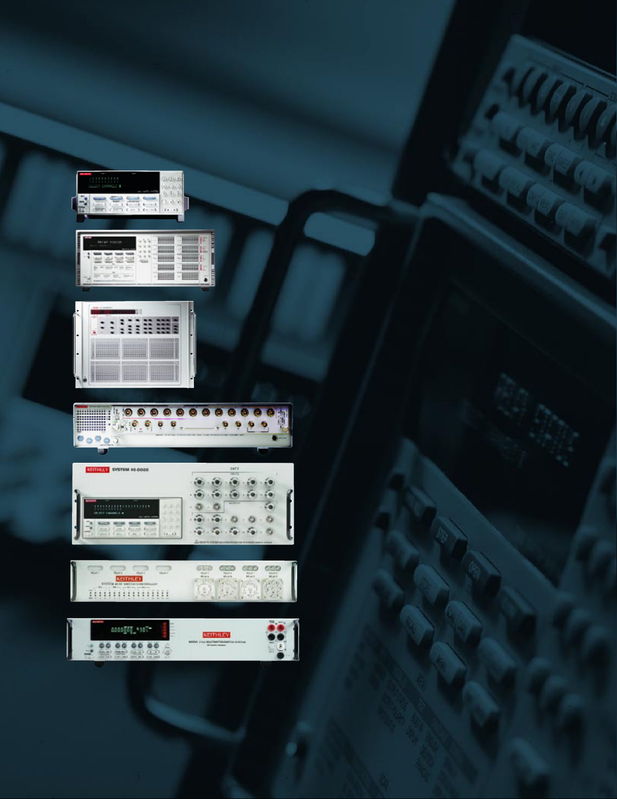
Robust and reliable
A wide array of high integrity switch systems
HIGH-CHANNEL-COUNT TEST SOLUTIONS
Our switch systems combine the most sensitive signal routing
in the industry with high ease of use.
Page 3

Keithley's great selection of switch systems makes it easy to
configure the optimum solution for just about any application. Both
standard and custom solutions are available. Whether the application
demands a switch matrix or multiplexer, or involves routing DC, RF,
microwave, optical, or digital I/O signals, Keithley offers a variety of
high performance, cost-effective solutions. Our switch systems:
Keithley has earned a reputation for designing and producing high quality switch
systems. Count on them to preserve measurement integrity while increasing
production test throughput and efficiency. Our systems have been carefully
designed and rigorously tested to ensure high reliability and long, robust life.
routing for all types of signals
EASY TO CONFIGURE THE OPTIMUM SOLUTION
Support a broad mix of signals to accommodate
virtually any application's requirements
Come with
outstanding technical support from
our team of experienced Applications Engineers
Make the most of limited
test rack space
Route low level signals
without
introducing errors
Ensure reliable, repeatable results
Allow quick and easy development, verification,
and troubleshooting of automated test systems with
well-designed front panels and remote interfaces
Page 4
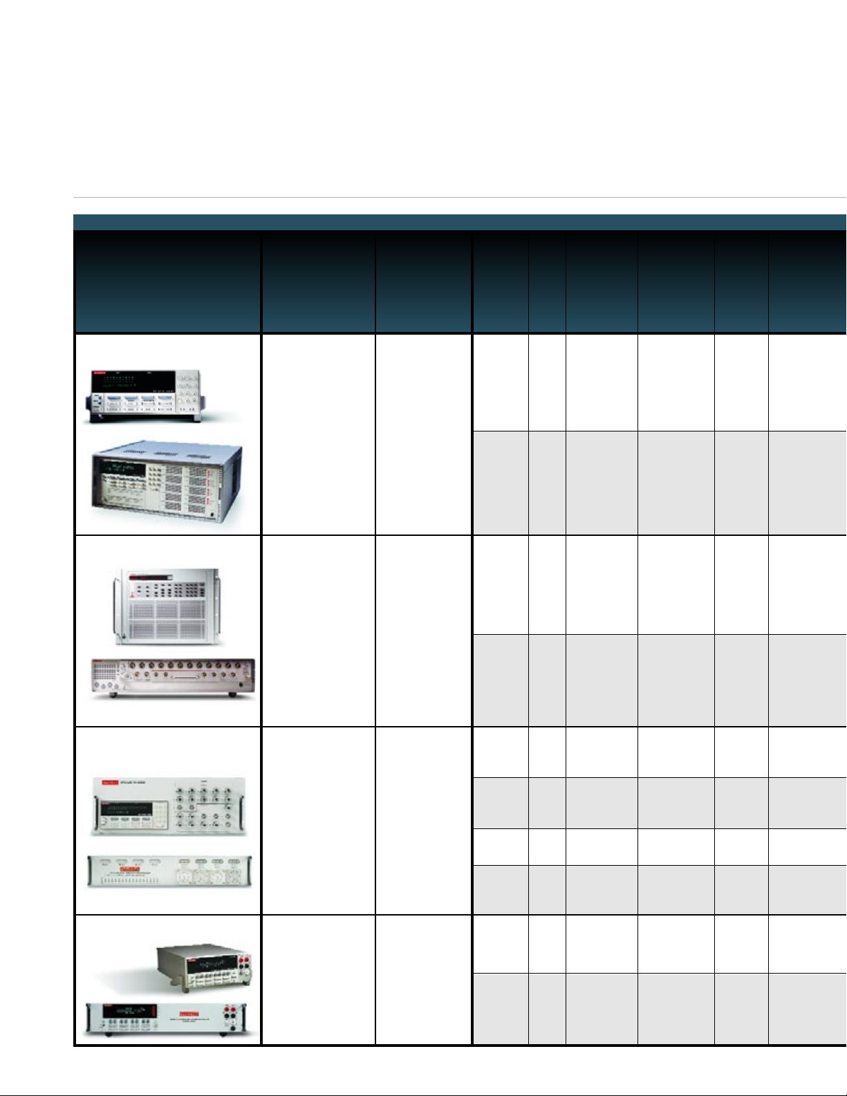
HIGHEST DENSITY, LOWEST COST SOLUTION
ATE Switch/Control Systems 7001
7002
2
10
Up to 80 per
mainframe
Up to
400 per
mainframe
With
Trigger Link
With
Trigger Link
Summary
Typical
Applications
Model
Number
Card
Slots
Max No. of
Channels or
Crosspoints
per Chassis Expandability
Switch/
Control
Cards
Available Front Panel
MAINFRAMES
More
than 40
More
than 40
Full status
display with
programming
control
Full status
display with
interactive
programming
• Widest signal range
• More than 40 switch
and control cards
with DC, RF, and
optical switching
capability and digital
I/O for control
• Great user interface
for front panel
operation and
debugging
• Wide range of
production test
applications,
including
functional test
of components,
sub-assemblies,
and systems
• Multipoint,
sensitive
measurements
• Mixed signal
switching for DC
and RF
• Large scale matrix
and multiplexer
capability
• Ultra-low current
capability
• Compatible with
Keithley and Agilent
parameter analyzers
• Semiconductor
device
characterization
• C-V testing
• Semiconductor
reliability testing
• Modeling
707A
708A
61Up to 576 per
mainframe
Up to 96 per
mainframe
Master/Slave 5
mainframes for
2880 channels
Master/Slave 5
mainframes for
480 channels
14
14
Full status
display with
interactive
programming
Full status
display with
interactive
programming
• Hybrid solutions for
RF/microwave,
optical, and low
frequency switching
• Standard and custom
signal routing solutions
• RF/microwave
switching up to 40GHz
• Integration of switches
and other RF
components
• Highest density,
lowest cost solution
• Integrated
multimeter
• Fully automatic
thermocouple
measurements
• Burn-in/data
logging
applications
• Production test
• Connector testing
and other low
ohms applications
2700
2750
2
5
Up to 80
channels or 96
crosspoints
per mainframe
Up to 200
channels or
240 crosspoints
per mainframe
With
Trigger Link
With
Trigger Link
9
9
Multimeter
display
Multimeter
display
• Cellular and
cordless phones
• RF components
• Specialized
mobile radios
• Base stations
• Wireless
peripherals
• Broadband wireless transceivers
• High speed digital
communications
System 40
System 41
System 46
7116-MWS
Custom
Custom
0
1
Custom
Up to 240
RF/microwave
chs.
Up to 32 RF/
microwave chs.
20 RF/micro-
wave and 40
general
purpose chs.
Custom
Custom
NA
NA
More
than 40
—
—
More
than 40
Full status display
with program-
ming control
Full status display
with program-
ming control
Status display
Full status display
with program-
ming control
Semiconductor Test System Switching
RF/Microwave Switch Systems
Switch/Measure Systems
for building powerful test systems
Industry leading switching performance
Page 5
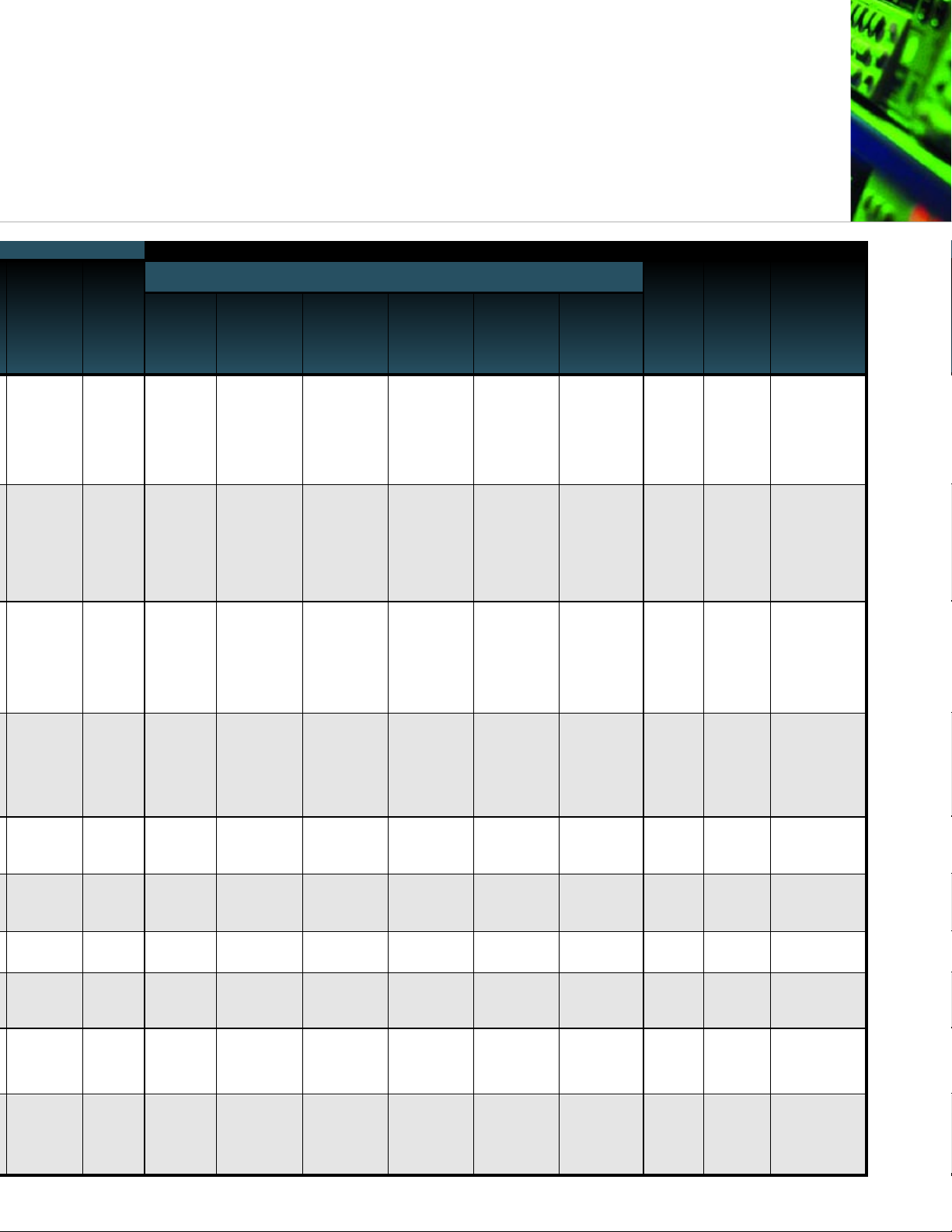
BOTH MATRIX AND MULTIPLEXER CAPABILITY
Built-in
Digital I/O
IEEE-488
Bus RF Optical
Integrated
Multimeter
DC
SWITCH/CONTROL CARDS
General
Purpose
V and I
Automatic
Cold Junction
Support for
Thermocouples
Low Current
Low Voltage High Current
High Voltage
1 input/
4 outputs
1 input/
4 outputs
Ye s
Ye s
•
•
•
•
•
•
•
•
•
•
•
•
•
•
•
•
8 inputs/
8 outputs
16 inputs/
16 outputs
2 inputs/
5 outputs
2 inputs/
5 outputs
*Available in early 2002
Ye s
Ye s
•
•
•
•
•
•
Custom
—
—
1 input/
4 outputs
Ye s
Ye s
Ye s
Ye s
•
•
•
•
•
•
•
•
•
•
•
•
•
•
•
•
•
*
*
Ye s
Ye s
•
•
•
•
•
•
Page 6
The compact, half-rack design of the Model 7001 conserves precious
rack space without sacrificing capability or ease of use. Its interactive
front panel provides maximum functionality. This design makes it
quick and easy to develop, verify, debug, monitor, and control an
application. The Model 7001 also provides built-in scan control,
accommodates the industry’s broadest range of signals, and won't
degrade signal integrity. If an application outgrows the Model 7001, it's
simple to move it to the Model 7002 because both systems are
software-compatible and share the same family of switch/control cards.
Features:
• Automatic card configuration. Just insert a card in a slot and the
Model 7001 does the rest.
• Built-in scan control eliminates the need for computer control,
providing higher production throughput.
• The Trigger Link function makes it easy to trigger multiple
instruments within a test system without computer interaction,
increasing speed and production throughput.
• Channel-status display and full control keypad shows the status
of each channel simultaneously, making it easy to monitor or
configure a test system, modify programs, and verify proper
operation during debugging.
• Digital I/O available on the rear panel and on many
switch/control cards.
• GPIB bus ensures reliable, high speed communications.
Specifications:
• Supports up to 80 channels or matrix crosspoints
per mainframe.
• Includes two card slots.
• Holds 100 discrete channel patterns in non-volatile memory.
• Scans 165 channels/second.
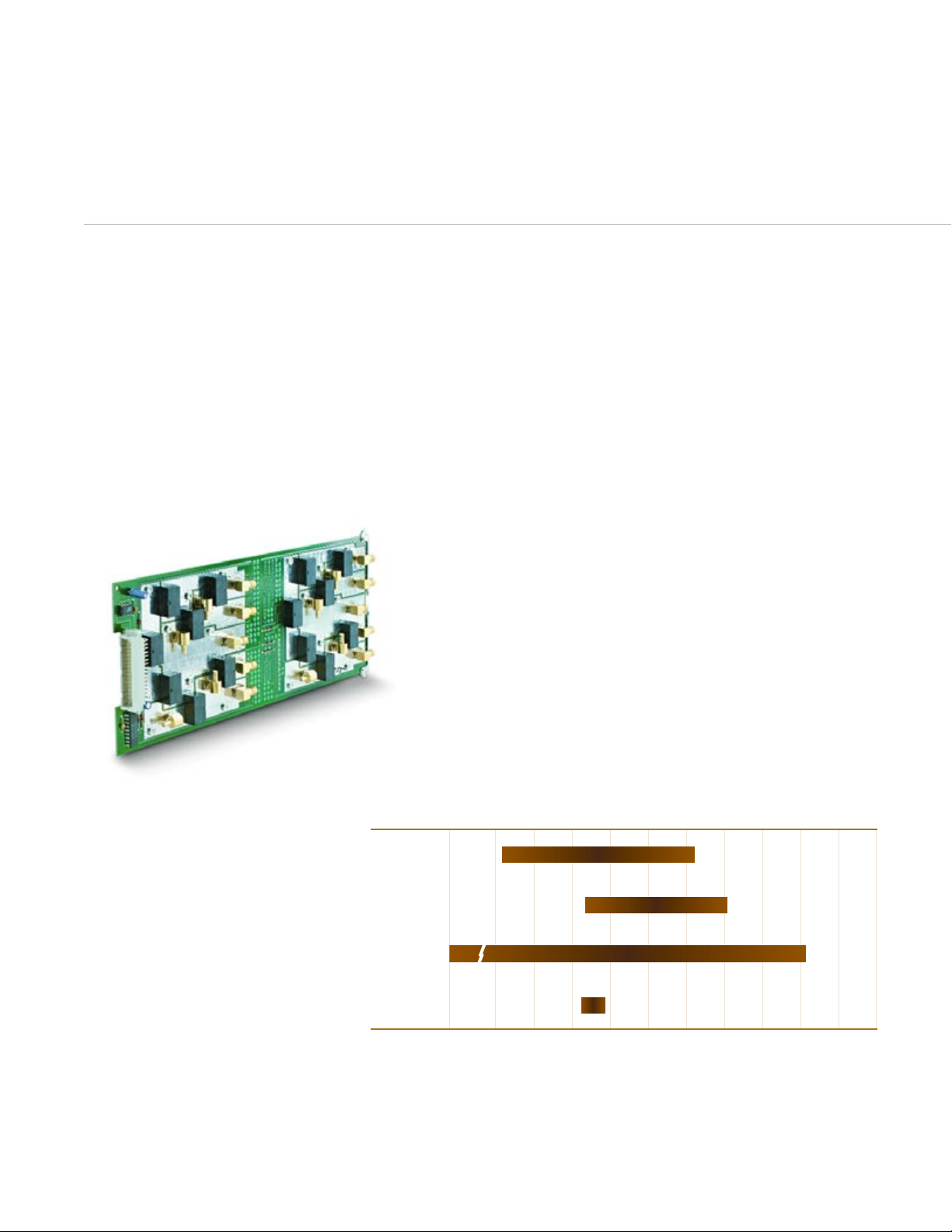
The two slots in the Model 7001 mainframe
support a family of more than 40
switch/control cards for routing the industry’s
widest range of electrical and optical signals
for production test and sensitive
measurement applications. These cards make
it easy to assemble a switch configuration that
will ensure signal integrity, minimize errors,
and prevent degradation due to offset voltage,
isolation resistance, and leakage current.
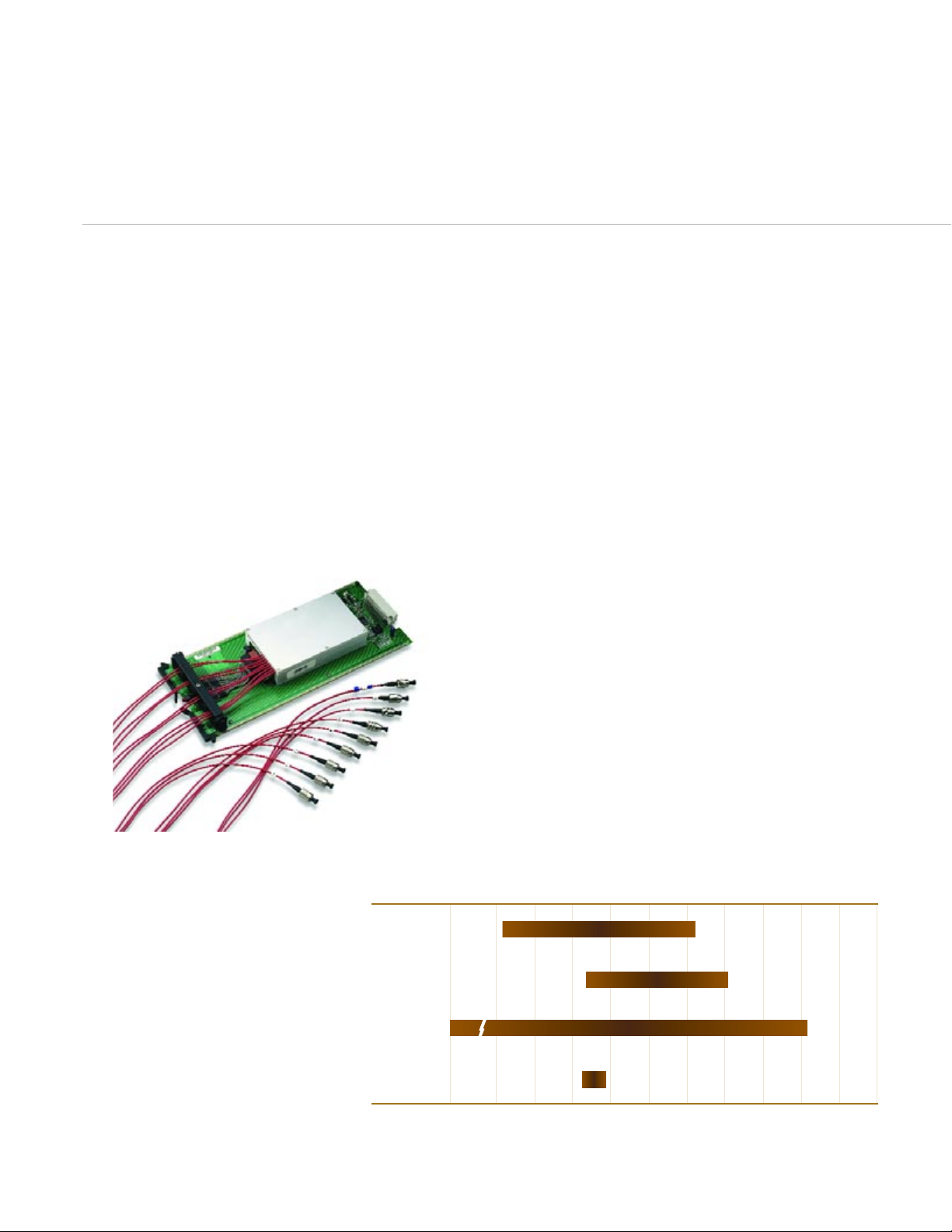
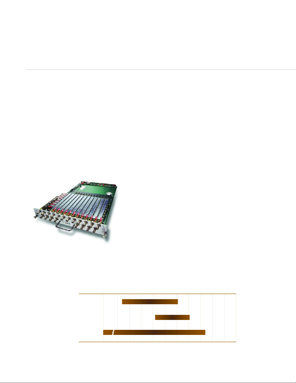
Range of signals supported by the Series 7000 switch/control cards
COMPACT, HALF-RACK DESIGN
all in one half-rack enclosure
DC, RF, and optical switching
Model 7001—packed with functionality for maximum simplicity and flexibility
Series 7000 switch/control cards provide Keithley's broadest
range of electrical and optical switching capabilities
fpnµm–kMGTP
10fA 5A
30nV 1.3kV
DC 2GHz
780nm
Current
Voltage
Electrical Signal
Bandwidth
Optical Signal
Wavelength
1650nm
Page 7
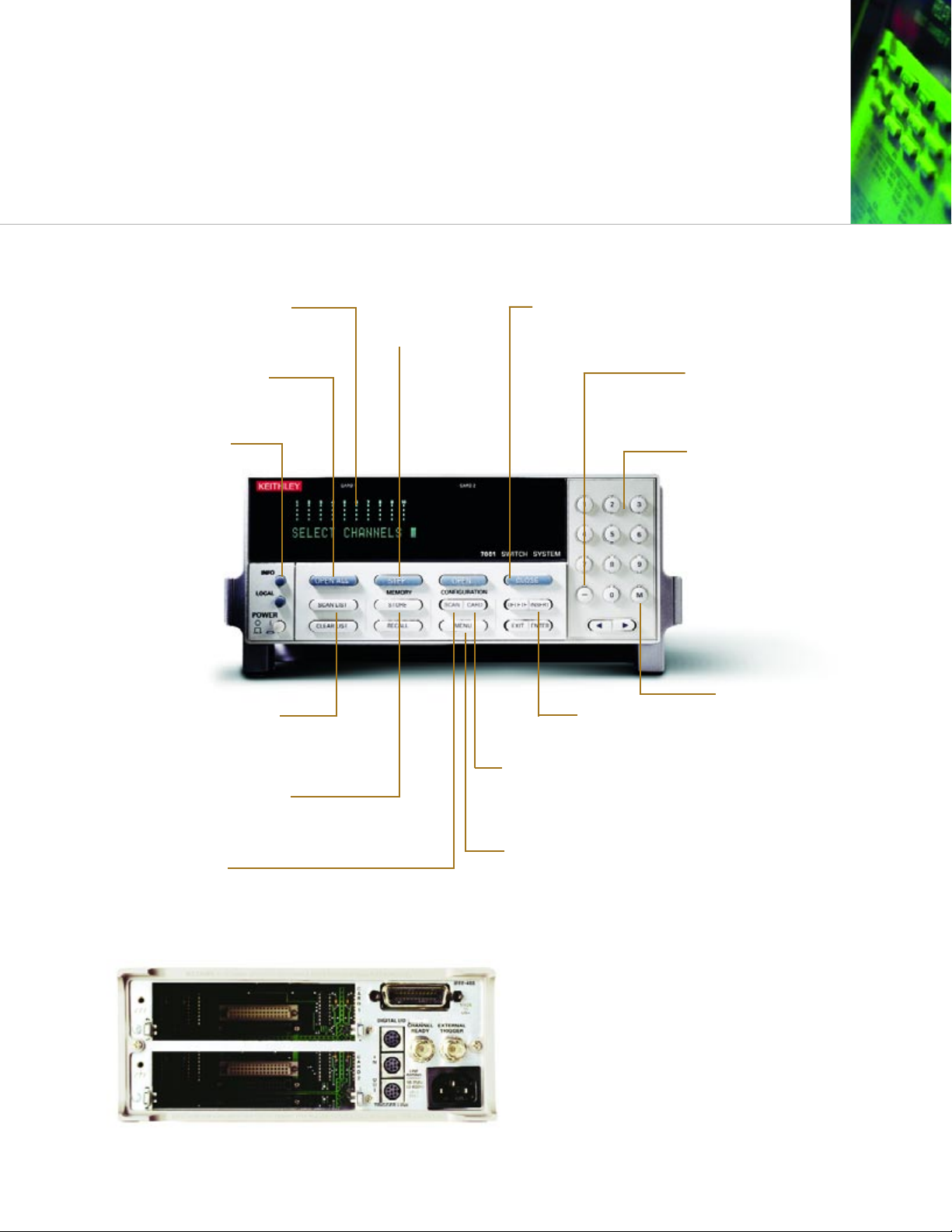
INTERACTIVE FRONT PANEL
Model 7001 80-Channel Switch and Control System
100 MEMORY LOCATIONS
Store and recall complete switch
patterns in non-volatile memory.
MAINFRAME CONFIGURATION
• Save 10 setups • Serial number
• Digital I/O control • Self test
• GPIB address
ON-LINE HELP
Context-sensitive information
provided with the push of a
single key.
MANUAL STEP
Step through a scan list
one channel at a time.
OPEN CHANNELS AND STOP SCANNING
Single-key operation.
SCAN THROUGH MEMORY
Memory locations can be
included in the scan list.
EDIT THE SCAN OR
CHANNEL LIST
SELECT SCAN SEQUENCE
Scan through channels
in any order. Also scan through memory.
EASY CARD CONFIGURATION
• Number of poles
• Card pair
• Channel delay
CHANNEL STATUS DISPLAY
Shows the open and close
status of each channel.
CHANNEL OPEN/CLOSE TOGGLE
Open and close a channel or list of channels
without re-entering the channel numbers.
KEY PAD
Makes channel selection
fast and easy.
SHORTHAND ENTRY NOTATION
Enter a list of contiguous channels
or memories without
entering each individually.
SCAN CONTROL
• Channel spacing • Triggering
• Scan spacing •Channel
• Number of scans restrictions
Rear-Panel Digital I/O
The Model 7001 can provide digital control through four open
collector outputs (each sinks up to 100mA) and one TTL input.
These features are standard, do not take up a card slot, and can be
controlled via the front panel or IEEE bus. Trigger inputs and
outputs allow timing coordination with multiple mainframes and
external instruments significantly faster than with the GPIB bus.
Page 8
DC, RF, and optical switching
for large-scale production
BROADEST RANGE OF SIGNALS IN THE INDUSTR
Y
Keithley's Model 7002 High Density Switch System supports the
broadest range of signals in the industry. This ten-slot mainframe
combines high performance with exceptional versatility for building
high quality matrix and multiplex switch configurations. Simple to
set up, program, and use, it's ideal for switch and control
applications involving voltage, current, RF, optical, and
thermocouple signals, as well as digital I/O and signal routing tasks.
Features:
• Ten-slot flexibility simplifies building systems with high channels
counts and diverse functionality.
• LED indicators continuously display the status of 400 channels
on every card simultaneously.
• Optional light pen provides point-and-click programming from
the front panel.
• Front panel control permits configuring the Model 7002
manually and displays error messages, on-line help, etc.
• Automatic card configuration. Plug in a card and the Model 7002
automatically configures the slot and displays the card's capacity
and configuration on the front panel.
• The Trigger Link function makes it easy to trigger multiple
instruments within a test system without computer interaction,
increasing speed and production throughput.
• Digital I/O available on the rear panel and on many
switch/control cards.
• GPIB bus ensures reliable, high speed communications.
Specifications:
• Accommodates ten switch/control cards.
• Supports up to 400 two-pole multiplexer channels or matrix
crosspoints.
• Scans 270 channels/second.
• Contains 500 memory locations.
• Just seven inches high.
The Model 7002’s ten card slots and more than
40 switch/control cards support the industry’s
widest range of signals and extremes in
measurements. These cards allow switching
signals from femtoamps to amps, nanovolts to
kilovolts, DC to 2GHz, and optical wavelengths
from 780nm to 1650nm.
Range of signals supported by the Series 7000 switch/control cards
Model 7002—for the most demanding applications
Series 7000 switch/control cards provide Keithley's broadest
range of electrical and optical switching capabilities
fpnµm–kMGTP
10fA 5A
30nV 1.3kV
DC 2GHz
780nm
Current
Voltage
Electrical Signal
Bandwidth
Optical Signal
Wavelength
1650nm
Page 9
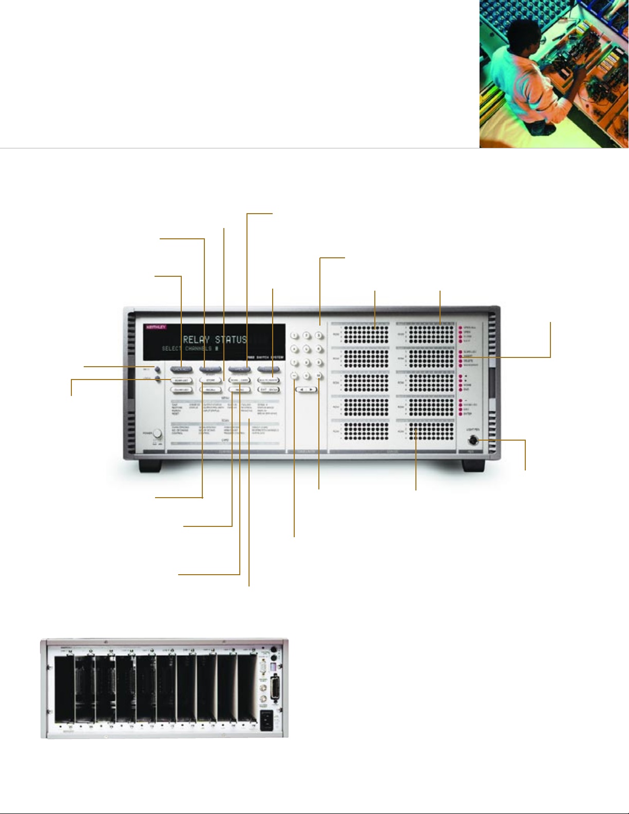
test systems
HIGH PERFORMANCE WITH EXCEPTIONAL VERSA
TILITY
500 MEMORY LOCATIONS
Store and recall complete switch
patterns in non-volatile memory.
MAINFRAME CONFIGURATION
• Save 10 setups • Serial number
• Digital I/O control • Self test
• GPIB address
ON-LINE HELP
Context-sensitive
information provided
with the push of a
single key.
MANUAL STEP
Step through a scan list
one channel at a time.
OPEN CHANNELS AND STOP
SCANNING Single-key operation.
SCAN THROUGH MEMORY
Memory locations can be
included in the scan list.
EDIT THE
SCAN OR
CHANNEL LIST
SELECT SCAN SEQUENCE
Scan through channels in
any order. Also scan
through memory.
EASY CARD CONFIGURATION
• Number of poles
• Card pair
• Channel delay
MULTILINGUAL
Messages and prompts can be
displayed in three languages.
LIGHT PEN
Provides functional
programming with
simple point and
click operation to
open or close the
desired channel or
crosspoint.
MATRIX CARD
DISPLAYED
Only the available
rows and columns
of the card are
displayed. Rows
are horizontal and
columns are vertical.
MULTIPLEXER CARD DISPLAY
The first row across represents
channels 1 to 10. The second
row is channels 11 to 20. Only
the available channels are
displayed.
CHANNEL OPEN/CLOSE TOGGLE
Open and close a channel or list of channels
without re-entering the channel numbers.
KEY PAD
Makes channel selection fast and easy.
OPEN CHANNEL
CLOSED CHANNEL
SHORTHAND ENTRY NOTATION
Enter a list of contiguous channels
or memories without
entering each individually.
SCAN CONTROL
• Channel spacing • Triggering
• Scan spacing • Channel
• Number of scans restrictions
Rear-Panel Digital I/O
The Model 7002 can provide digital control through four open
collector outputs (each sinks up to 100mA) and one TTL input.
These features are standard, do not take up a card slot, and can
be controlled via the front panel or GPIB bus. Trigger inputs and
outputs allow timing coordination with multiple mainframes and
external instruments significantly faster than with the GPIB bus.
Model 7002 400-Channel Switch and Control System
Page 10
OUTSTANDING LOW CURRENT MATRIX CAPABILITY
Semiconductor test system switching
for characterization and reliability
The Model 707A and 708A provide outstanding low-current matrix
capability and let you control up to 2880 channels or matrix
crosspoints in real time. Their large matrix format makes them well
suited for your large ATE system applications such as semiconductor
device characterization, wafer level reliability, parallel test, and
modeling. They are most often used in conjunction with Keithley’s
Model 4200-SCS semiconductor characterization system and Model
590 and 595 C-V analysis instrumentation.
Features:
• Fully configurable and controllable from the Model 4200-SCS
characterization system front panel—for seamless integration in
I-V and C-V applications.
• Easy integration with the Agilent 4155/56—gives industry
wide compatibility.
• High capacity—with up to 6 cards linked via the
Model 707A backplane you can build pin configurations of
up to 8 rows x 72 columns per mainframe.
• Expandable—up to 5 mainframes can be connected
through the master/slave feature and controlled from a
single GPIB address.
• Fully interactive front panel with optional light pen control—for
simple configuration in stand-alone applications.
Specifications of Model 707A/708A:
• Supports up to 576/96 channels, expandable to 2880/480
channels.
• Contains 6/1 card slot(s).
• Scans 200 channels/second.
• Contains 100 memory locations.
• Includes 16/8 digital inputs and 16/8 digital outputs.
• Fits into a 19 inch rack and is 14/3.5 inches high.
A family of more than a dozen switch/control cards designed for
semiconductor characterization applications can be used in the
Model 707A and 708A. Some of the switch cards are general
purpose like the Model 7071, while others have very unique
capabilities, such as the Model 7174A card, which is an 8 x 12
configuration with 10fA typical offset current on all signal paths.
The Model 7072 card combines low current and high frequency
capability for C-V characterization to 1MHz.
Model 707A and 708A—large-scale matrix systems for
world-class low current performance
Switch/control cards for the Model 707A and 708A
Range of signals supported by the Model 707A and 708A switch/control cards
Model 7174A
fpnµm–kMGTP
100fA 2A
5µV 1.3kV
DC 200MHz
Current
Voltage
Electrical Signals/
Bandwidth
Page 11
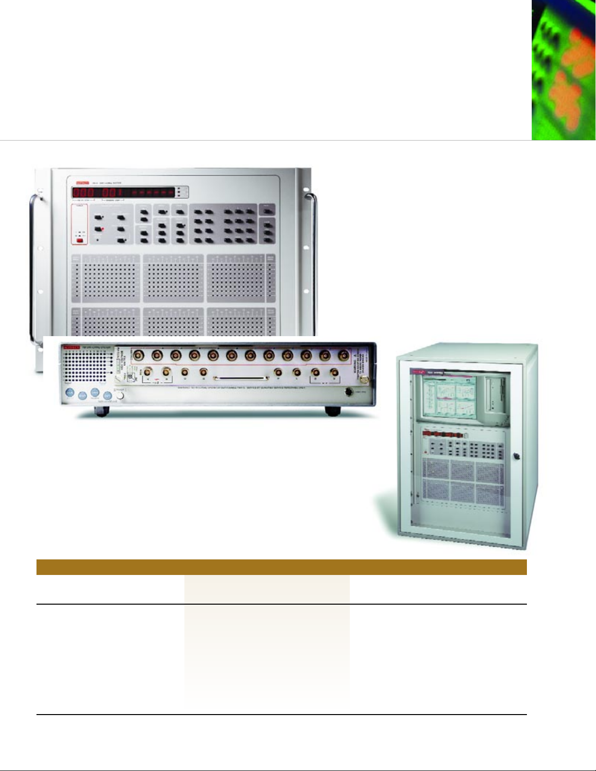
The interactive front panels of the Model 707A and
708A allow full configuration of these mainframes
during test design and troubleshooting of DUTs.
LEDs display the real-time status of all matrix
crosspoints. Open or close each crosspoint with a
simple point and click of the optional light pen.
IDEAL FOR LARGE ATE SYSTEM APPLICATIONS
Standard Switch Matrix Configurations for I-V and C-V Characterization
GENERAL PURPOSE
>100pA
Uses Model 7071 switch card
LOW CURRENT
>1pA
Uses Model 7072 switch card
ULTRA LOW CURRENT
<100fA
Uses Model 7174A switch card
• Component ATE
• Best match to the 4200-SCS without
optional PreAmps
• Excellent for remote sense applications
• Low cost, high density cables
• Expandable from 8 x 12 to 8 x 72
• Basic device characterization
• Good match to the 4200-SCS with or
without optional PreAmps
• Local sense, excellent for C-V meters and
pulse generators
• Standard triax cables
• Expandable from 8 x 12 to 8 x 72
• High performance device characterization
• Best match for the 4200-SCS when equipped
with optional PreAmps
• Local or remote sense, excellent for C-V
meters and pulse generators
• Standard triax cables
• Expandable from 8 x 12 to 8 x 72, local sense
• Expandable from 6 x 6 to 6 x 30, remote sense
Page 12
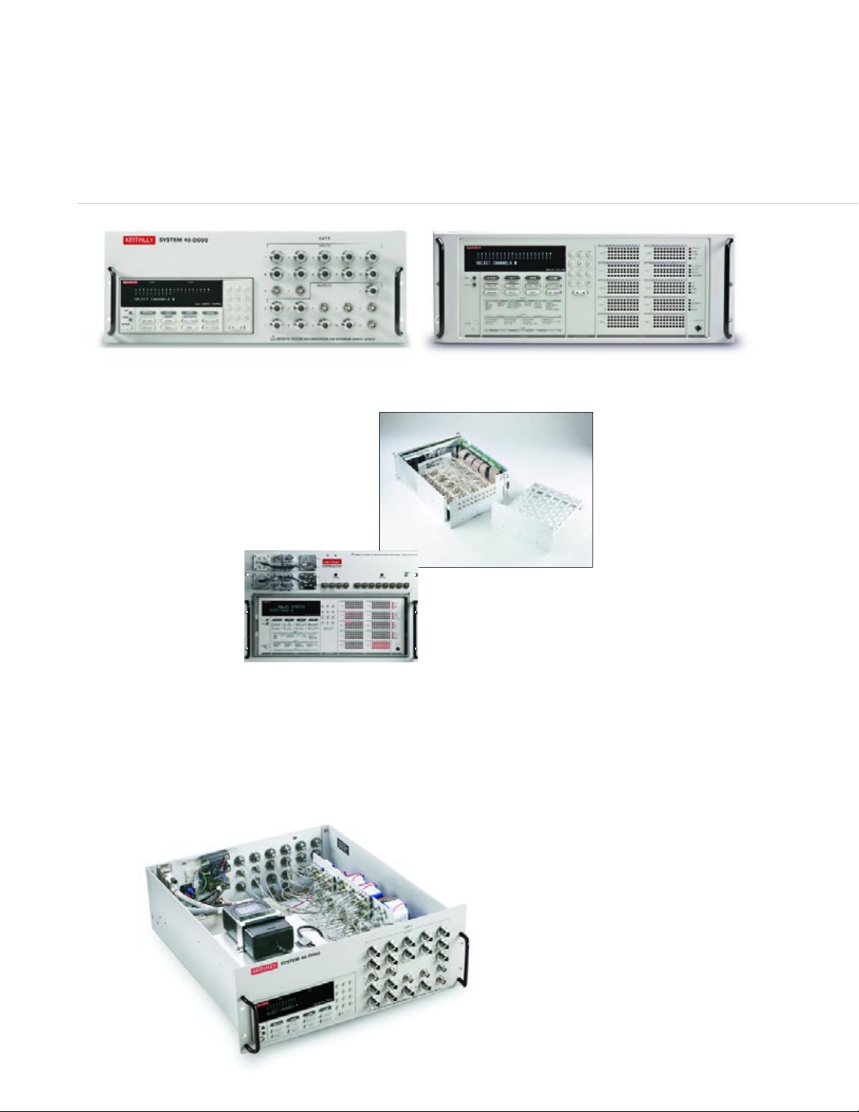
RF/microwave switch systems
Standard and custom designs
System 40—the ultimate in
hybrid customization
System 40 signal routing solutions are designed and built
to match specific application requirements from DC to
40GHz. Create a hybrid switching solution by
incorporating RF/microwave, optical, and low frequency
switching. Each System 40 is built around a standard
Model 7001 or 7002 controller, incorporating
local/remote control and continuous real-time display.
• Integrate
RF/microwave,
optical, and low
frequency switching
for a unique hybrid
solution.
• Fully customizable
chassis.
• RF/microwave switches including: SPDT, Multipole up to SP12T,
and transfer switches.
• RF/microwave component integration, including:
– Fixed and programmable attenuators.
– Isolators, circulators, filters.
– Couplers, dividers, combiners.
– Amplifiers, splitters, bias tee.
System 41—for superior
RF/microwave performance
The System 41 is optimized for
RF/microwave signal routing
applications. It provides the
ability to control up to 240
RF/microwave channels within
a seven-inch-high chassis. To
enhance accessibility, switches
are mounted on an easily
removable RF module. Standard
RF modules are available or a custom RF module can be designed
to fit a specific application.
• LED indicators continuously display the status of all channels
and crosspoints for easy monitoring during operation.
• Manual and automatic operation of the system speeds and
simplifies test verification and troubleshooting.
• Optional light pen allows easy front panel programming.
• Easily accessible RF input/output connections ensure fast and
uncomplicated system setup and maintenance.
Standard modules for 18GHz switching include:
•6
x 6 non-blocking matrix
•10
x10 non-blocking matrix
•1
x 72 multiplexer
• Two individual 1
x 36 multiplexers
• Custom modules are available
DESIGNED TO SPECIFIC APPLICATION REQUIREMENTS
Page 13
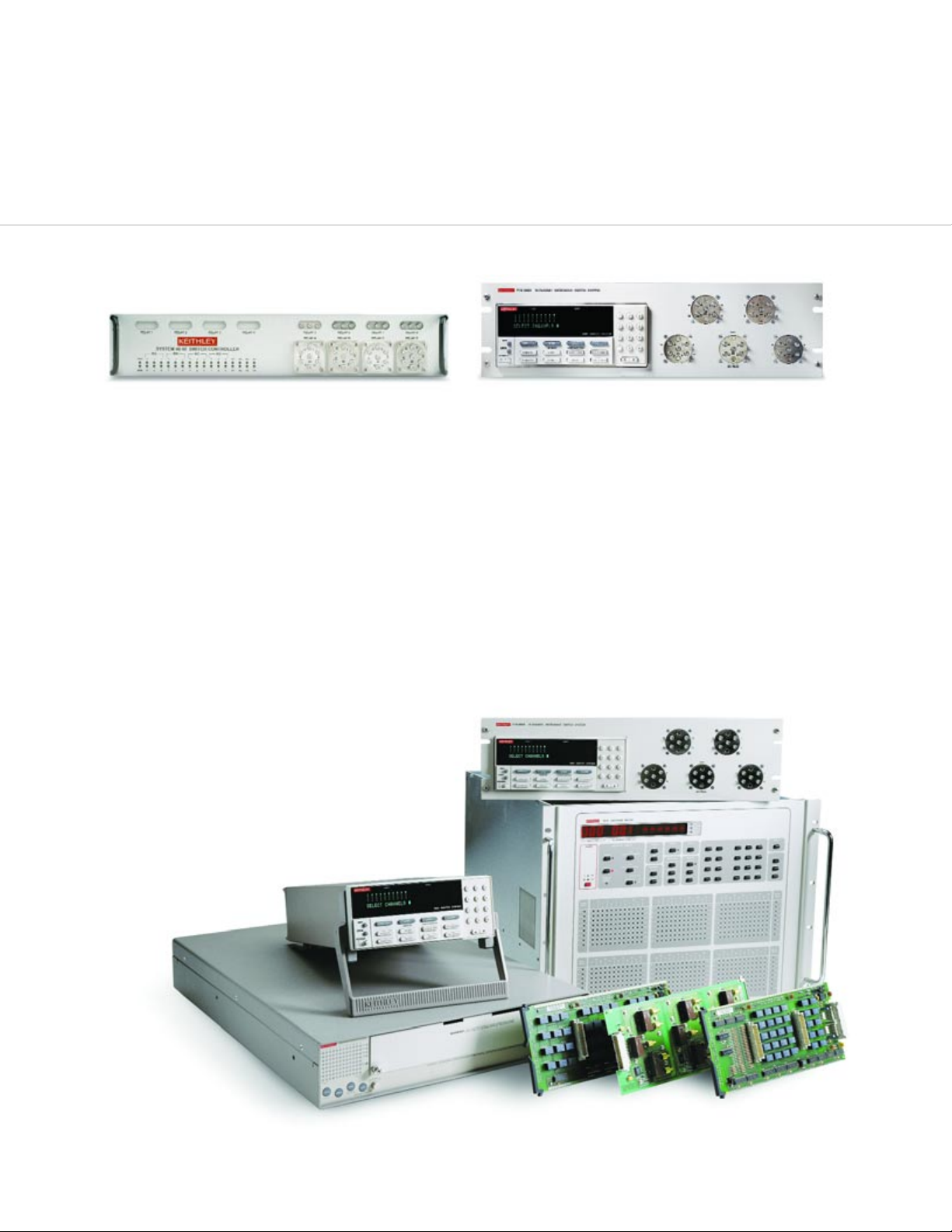
Model 7116-MWS—standard solution
with great performance
When the application does not require the extended flexibility of a
custom system, this pre-configured solution can accommodate
RF/microwave signal switching for a wide range of communication
devices and systems. It is configurable as one 1
x 16 or five
independent 1
x 4 multiplexers. It includes a switch control unit and
RF/microwave coaxial relays with a bandwidth from DC to 18GHz.
• Channel status display and full control keypad shows the status
of each channel.
• Easy access to RF input/output connections from front panel
permits easy maintenance and reconfiguration.
System 46—designed to exacting
specifications
The System 46 is a low-cost, quickly deliverable 18GHz switch
system. The unit supports up to eight single-pole double throw
(SPDT) and four multi-pole relays (SP4T to SP6T) in a small 2U
high (3.5 inch) full-rack enclosure. Standard solutions can
include multiplexers as large as 1
x 18 and non-blocking matrices
as large as 2
x 6.
• LED indicators continuously display the status of all
relay contacts.
• Relay contact closures are counted automatically to
determine mechanical contact wear.
• Store characterization data for trending system performance.
• Optional relay kits allow for future expansion or
switch replacement.
for a perfect fit
JUST WHAT YOU NEED AND NO MORE
Page 14
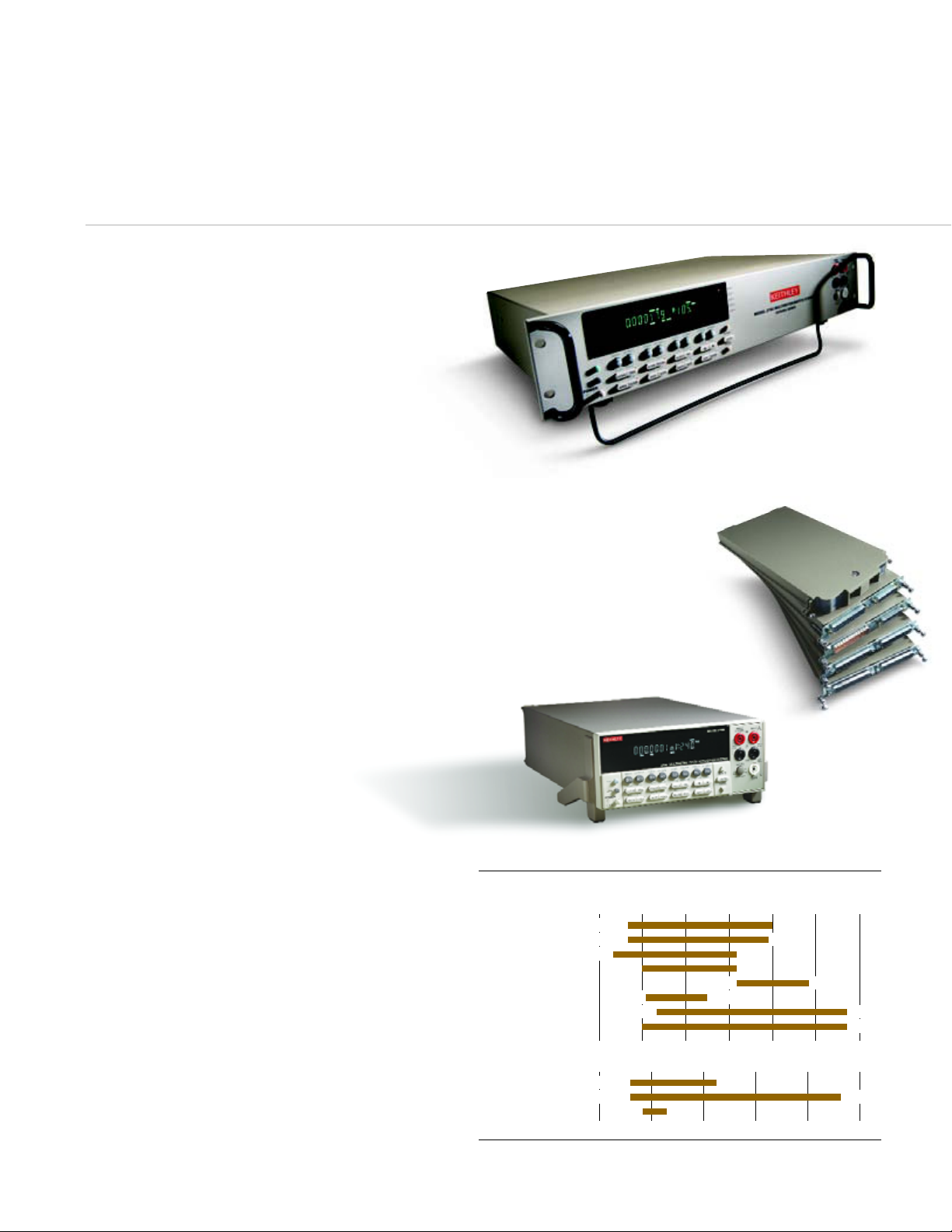
Low cost switch/measure systems
Integra Series switch and
measurement systems
An Integra system brings together tremendous functionality in one
small package: the ability to perform scans, measurements,
switching, and datalogging. The Models 2700 and 2750 are highly
integrated systems that offer versatile, yet affordable, solutions to
multipoint test, measurement, and control applications. Applications
for Integra systems include production testing of electronic
products and devices, accelerated stress testing, process monitoring
and control, and low ohms, multichannel measurements.
Features:
• Built-in true 6
1
⁄
2-digit multimeter. A single integrated
system allows performing both measurement and switching
tasks more efficiently.
• Automatic thermocouple cold junction compensation. Just
connect the thermocouples and start taking readings.
• Traceable, repeatable measurements reduce false failures.
• Outstanding system throughput. Tight coupling of the DMM
and switch optimizes system speed and triggering.
• Built-in relay counters monitor the life of relays for easy
preventive maintenance.
• Industry standard connectors are used on all plug-in modules
for simple wiring and cabling.
• Robust battery backup. If the power goes out, all data is
saved. When power returns, the system can resume
scanning on its own.
• Free start-up software. Gets applications up and running quickly.
Model 2700/2750 specifications:
• Includes two or five card slots.
• Supports up to 80/200 channels.
• Supports up to 96/240 matrix crosspoints.
• Allows scanning and measuring 185/200 channels/second.
• Performs 2500 readings/second on a single channel.
• Offers true 6
1
⁄2-digit (22-bit) resolution.
• Provides ±1°C thermocouple system accuracy.
Integra Series switch/control modules
The nine switch/control modules for the Model
2700 and 2750 support a wide range of
applications with multiplexer, matrix,
independent switch, analog I/O, and digital I/O
configurations. Modules can be connected
automatically to the internal DMM with isolation relays
for full data acquisition capability or used in switch-only
mode to provide maximum flexibility.
packed with functionality for
Temperature–RTD
Temperature–TC
Temperature–Thermistor
Linear scale
1n 1µ 1m 1 1k 1M 1G
100nV 1000V
100nV 750V
10nA 3A
1µA 3A
3Hz 500kHz
2µs 333ms
–200°C 630°C
–200°C 1820°C
–80°C 150°C
10µΩ 120MΩ
1µΩ 120MΩ
DC Voltage
AC Voltage
DC Current
AC Current
Frequency
Period
Resistance (2-Wire)
Resistance (4-Wire)
Logarithmic scale
–500 0 500 1000 1500 2000
Model 2750 Measurement Ranges
TREMENDOUS FUNCTIONALITY IN ONE SMALL P
ACKAGE
Page 15
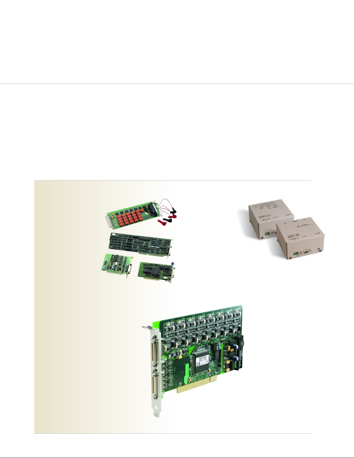
DMM scanner cards
The Keithley Series 2000
multimeters and the Series 6500
electrometers are available with
optional plug-in switch modules,
which can provide up to 20
channels of scanning and
switching capability.
GPIB boards
Keithley's GPIB (IEEE-488) boards add
standard GPIB bus control to a PC. They include complete
programming language support for a wide range of
languages. Keithley offers GPIB boards for PCs that contain
PCI, ISA, and PCMCIA slots.
Digital I/O boards
For applications that require additional digital I/O
lines, a wide range of digital I/O boards are available.
See the complete list of Keithley digital I/O boards at
www.keithley.com.
Model KPC-TM Trigger Master
The Trigger Master interface card provides complete
timing control over the GPIB instruments in a system
without sacrificing throughput. The KPC-TM plugs into
the system's PC, giving it direct control over the
hardware triggers of the instruments in the test setup.
This provides maximum throughput, while allowing the
KPC-TM to start and stop a process easily at any time.
Model 7999-4 and
7999-5 RS-232 Switch
and Relay Controller
These products reduce the amount
of RF/microwave cabling needed in a
system, which increases signal integrity.
These stand-alone units are easy to place almost
anywhere in the test environment. The Model 7999-4
is a control unit that contains a DC-18GHz SPDT switch.
The Model 7999-5 is a 16-channel switch controller with 16 open
collectors. Each of its open collectors can sink 300mA at 28VDC,
allowing them to control switches and other devices. Both models
include an RS-232 control interface.
datalogging and production test applications
Accessories
Maximize flexibility, capabilities, and ease of use with these accessories
EASY TO PLACE ALMOST ANYWHERE IN THE TEST ENVIRONMENT
Page 16

Switching Handbook
Request a FREE copy of Keithley's
Switching Handbook. This reference
book describes switching components,
topologies, and functions, relay
characteristics, and other
background information. It also
provides selection criteria, system
integration hints, guidelines for
optimizing test systems, and examples.
Keithley's expert applications
engineers are here to help
Selecting and configuring a switch system can sometimes be
confusing. For example, which switch topology is best for your
application? Which type of relay should you use? Keithley's
Applications Engineers are experts in their fields
(telecommunications, optoelectronics, semiconductors, etc.)
and are here to help, before and after the sale.
With more than a half-century of expertise in making demanding low
level measurements, Keithley offers its customers a greater measure
of testing confidence on the production floor, in the QA lab, and in
R&D. For more information on how Keithley test solutions can help
you keep pace with changing technologies, call your local Keithley
sales engineer or visit our website.
For applications assistance, call us on our toll-free hotline
1-888-KEITHLEY (534-8453) from 8:00 am to 5:00 pm ET (U.S. only).
If you need assistance beyond those hours, send our Applications
Engineering Department a facsimile (440-248-6168) or an e-mail
message ([email protected]) and we’ll respond as soon as
possible. Applications assistance is also available via the web, with
many reference materials available online, as well as convenient forms
for contacting our Applications Engineers. Keithley maintains facilities
and affiliates worldwide, which offer native language support services.
Visit our web site for current listings:
www.keithley.com
A greater measure of confidence All the support you need
Specifications are subject to change without notice.
All Keithley trademarks and trade names are the property of Keithley Instruments, Inc.
All other trademarks and trade names are the property of their respective companies.
Keithley Instruments, Inc. 28775 Aurora Road • Cleveland, Ohio 44139 • 440-248-0400 • Fax: 440-248-6168
1-888-KEITHLEY (534-8453) • www.keithley.com
Sales Offices: BELGIUM: Bergensesteenweg 709 • B-1600 Sint-Pieters-Leeuw • 02-363 00 40 • Fax: 02/363 00 64
CHINA: Yuan Chen Xin Building, Room 705 • 12 Yumin Road, Dewai, Madian • Beijing 100029 • 8610-6202-2886 • Fax: 8610-6202-2892
FINLAND: Tietäjäntie 2 • 02130 Espoo • Phone: 09-54 75 08 10 • Fax: 09-25 10 51 00
FRANCE: 3, allée des Garays • 91127 Palaiseau Cédex • 01-64 53 20 20 • Fax: 01-60 11 77 26
GERMANY: Landsberger Strasse 65 • 82110 Germering • 089/84 93 07-40 • Fax: 089/84 93 07-34
GREAT BRITAIN: Unit 2 Commerce Park, Brunel Road • Theale • Berkshire RG7 4AB • 0118 929 7500 • Fax: 0118 929 7519
INDIA: Flat 2B, WILLOCRISSA • 14, Rest House Crescent • Bangalore 560 001 • 91-80-509-1320/21 • Fax: 91-80-509-1322
ITALY: Viale San Gimignano, 38 • 20146 Milano • 02-48 39 16 01 • Fax: 02-48 30 22 74
KOREA: 2FL., URI Building • 2-14 Yangjae-Dong • Seocho-Gu, Seoul 137-130 • 82-2-574-7778 • Fax: 82-2-574-7838
NETHERLANDS: Postbus 559 • 4200 AN Gorinchem • 0183-635333 • Fax: 0183-630821
SWEDEN: c/o Regus Business Centre • Frosundaviks Allé 15, 4tr • 169 70 Solna • 08-509 04 679 • Fax: 08-655 26 10
SWITZERLAND: Kriesbachstrasse 4 • 8600 Dübendorf • 01-821 94 44 • Fax: 01-820 30 81
TAIWAN: 1FL., 85 Po Ai Street • Hsinchu, Taiwan, R.O.C. • 886-3-572-9077• Fax: 886-3-572-9031
© Copyright 2001 Keithley Instruments, Inc. No. 1582
Printed in the U.S.A. 100125KCG
 Loading...