

Page 1
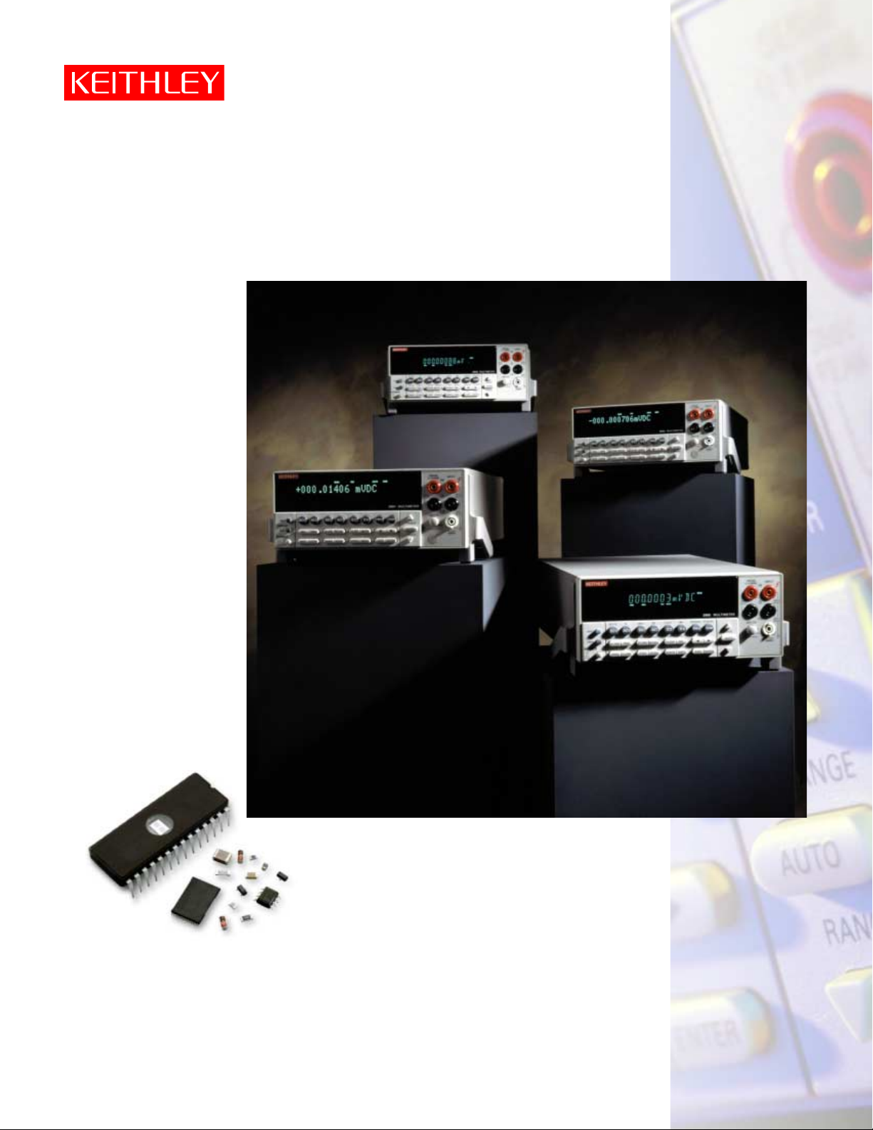
Series 2000 High-Performance
Digital Multimeters
2000 61⁄2-Digit DMM
2010 Low-Noise DMM
2001 7
1
⁄2-Digit DMM
2002 8
1
⁄
2-Digit DMM
Page 2
2
Keithley’s Series 2000 Digital Multimeter Family
The unique combination of measurement capabilities each
instrument offers makes them ideal for a broad range of highspeed production testing applications, including device testing
of electronic components, telecommunications products, automotive components and subassemblies, etc. The space-saving
half-rack design means they’ll fit readily into just about any
production floor test rack or benchtop. A built-in scanner
mainframe makes it easy to do multi-point testing of up to 10
test points, simply by plugging in an economical switch card.
With a choice of resolution from 61⁄2
to 8
1
⁄2
digits, there is sure to
be a Series 2000 DMM that’s appropriate for your application.
Shared core technologies
All four Series 2000 DMMs are designed on the same set of
core technologies, so they share many of the same basic
capabilities. For example, the entire family is based on the same
high-speed, low-noise 28-bit A/D converter technology. The
high-end Models 2001 and 2002 incorporate five distinct pro-
cessors for tighter A-to-D control, higher accuracy, more precise
triggering, and higher throughput. All are capable of reading
rates of up to 2000 readings/sec (at 4
1
⁄2 digits) for fast throughput
in production test applications. Their wide dynamic range
minimizes range-shift errors and speeds systems applications.
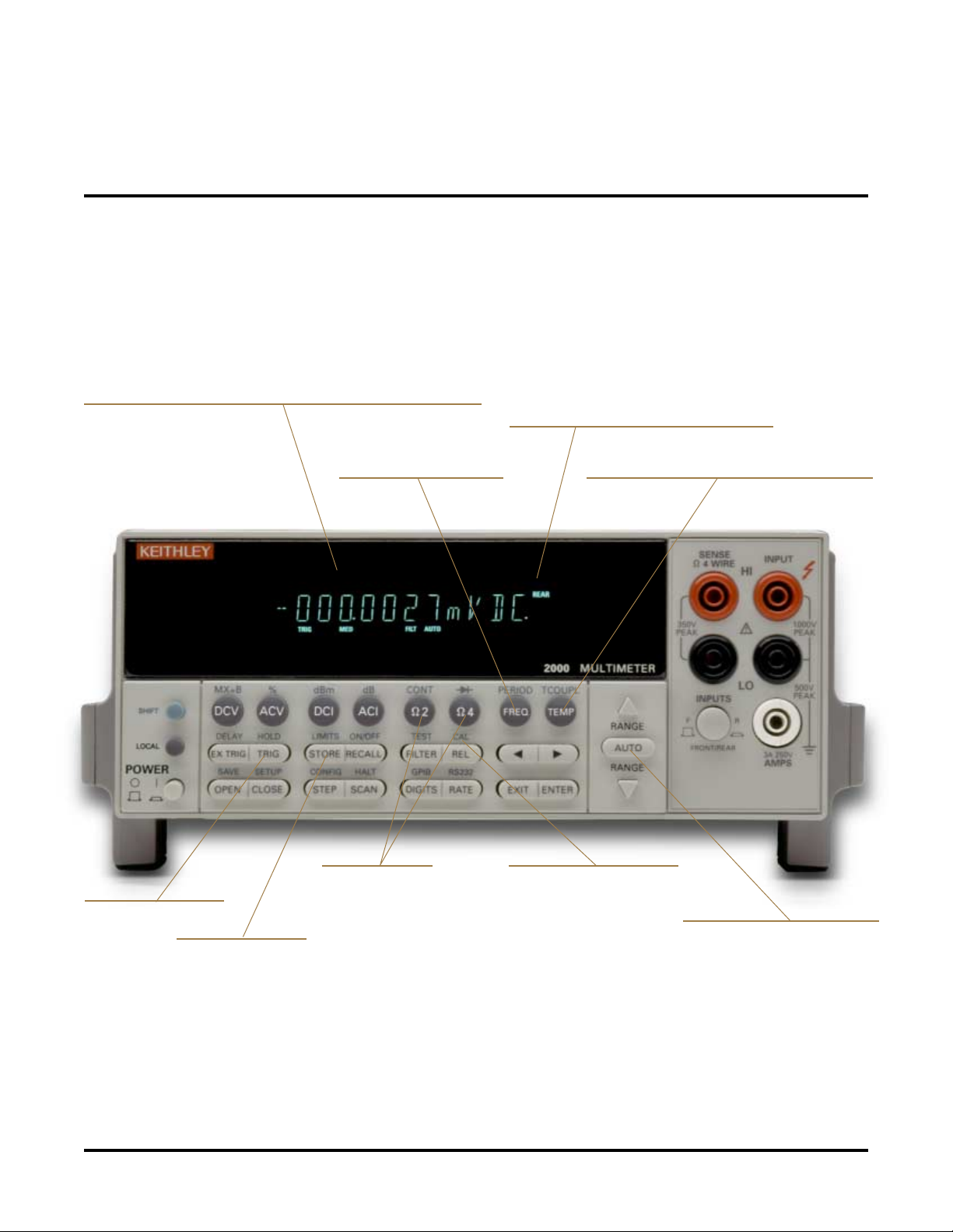
Easy-to-read vacuum fluorescent display with clear annunciators
Data storage memory
Selectable reading rates up to 2000 rdgs/s
2- or 4-wire ohms
measurements
Fast, flexible triggering
Easy closed-case calibration
Built-in temperature measurement capabilities
Built-in frequency counter
Fast range and function changes
Page 3
3
Other Series 2000 capabilities that contribute to high measurement throughput include fast range and function changes, highspeed auto-ranging, and fast overload recovery. The 2001 and
2002 feature very low trigger delay and triggering uncertainty.
The vacuum fluorescent display has clear annunciators and is
designed for easy reading, even in low light conditions. The
front panel design is simple to understand and use. This intuitive
front panel design helps minimize the user’s learning curve
when migrating an application from one Series 2000 meter to
another. The software architecture was also designed to make it
easy to substitute a Series 2000 meter for meters from other
manufacturers or replace one Series 2000 meter with another.
High performance plus high value
Series 2000 meters offer measurement stability, speed and
accuracy specifications comparable to instruments costing
thousands of dollars more. Other features that enhance their
value include a built-in scanner mainframe with optional 10channel switching capacity for multi-point testing applications. This option slot also opens the door to accessories and
companion products that can add new features, functions, and
measurement ranges to the instruments. The high compatibility of Series 2000 DMMs also eliminates the need to buy
multiple versions of the same accessory or companion product
in many cases.
Easy interfacing
All Series 2000 DMMs offer IEEE-488 interfaces for
interfacing the meter with a computer controller for larger test
applications. Several features also allow them to operate in
stand-alone mode, without the need for a PC controller, such as
their built-in math functions, non-volatile storage buffers, builtin switch mainframes, etc. The Models 2000 and 2010 also
include an RS-232 interface for simple low cost PC interfacing.
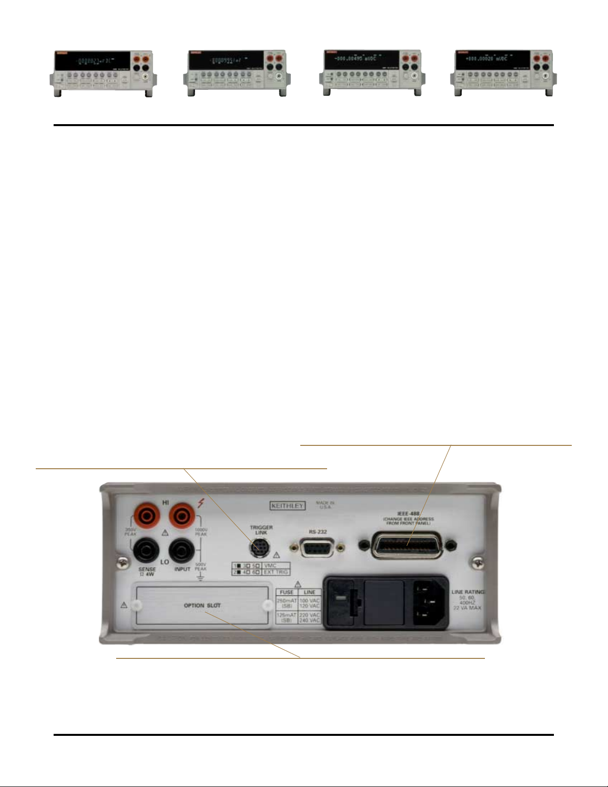
Built-in scanner mainframe accepts optional switching cards for 10-channel multi-point testing
IEEE-488 bus simplifies controlling a wide range of GPIB instruments
Trigger-Link for fast, precise, repeatable triggering of multiple instruments
Model 2000 Model 2010 Model 2001 Model 2002
Page 4
4
Model 2000 61⁄
2-Digit Digital Multimeter
High performance without the high cost
Using a precision, low-cost A-to-D converter enabled the Model
2000 design team to develop a unique error reduction algorithm.
This algorithm corrects for drift errors associated with the
resistor networks used for signal conditioning. Therefore, it
allows the use of inexpensive resistor networks, while providing
higher accuracy.
A shared solid-state circuit protects the Model 2000’s DC volts,
AC volts and ohms circuitry from overloads. This circuit provides
low offset error and drift, and fast response to and recovery from
overloads. Traditional techniques for protecting these circuits
would have required three separate (and expensive) circuits.
The Model 2000’s design also helps control costs by using a
two-layer printed circuit board rather than a traditional four- or
six-layer board, which can double or quadruple board manufacturing costs.
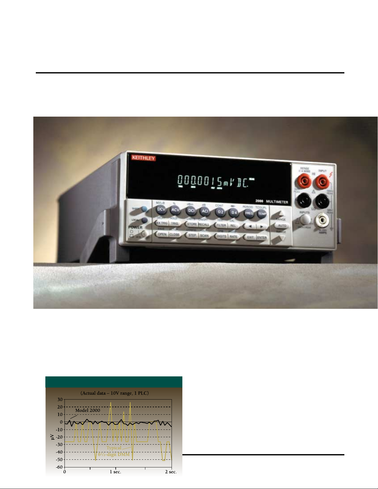
2000 STABILITY PERFORMANCE
T echnical innovations allow the Model 2000 to provide high per formance economically. Traditional DMMs require autozeroing
the front-end amplifier to reduce offset drifts, slowing the reading
rate. The Model 2000’ s proprietary servo front-end amplifier has
extremely low offset drift, reducing the need for autozeroing and
increasing throughput for high accuracy measurements.
Page 5
5
High-speed production testing
In addition to the high performance features common to all Series
2000 DMMs, the Model 2000 offers unique capabilities that
simplify building and upgrading automated
production test systems. These include a
built-in limit testing function, which can be
used to sort or grade components or assemblies. It also offers a full resolution reading
rate (50 rdg/s) that’s nearly ten times faster
than any other meter in its class and a
maximum speed of 2000 rdg/s. A variety
of built-in math functions (Rel, Min/Max/
Average/StdDev (of stored reading), dB,
dBm, Limit Test, %, and mX+b) allow
making calculations on acquired data
without a computer. The built-in 10channel scanner mainframe simplifies making multi-point measurements—just plug in an economical
switch card.
Easy system upgrades
The Model 2000 can preserve your
investment in control software when
you use it to upgrade the performance
of an existing application. If the existing IEEE-488 test code was written for
the Fluke 8840/42 or the Keithley
196/199, an emulation mode makes it
easy to substitute the Model 2000 for
the old DMM without modifying the
software in most cases. Later, if the
application needs the additional resolution or functionality of the Model
2010, 2001 or 2002, the Model 2000 ensures a smooth migration
path to higher performance via the SCPI command set.
Accessories and companion products
• Model 2000-SCAN: 10-Channel Scanner
• Model 2001-SCAN: 10-Channel Scanner
(with two high-speed channels)
• Model 2001-TCSCAN: 9-Channel
Thermocouple Scanner
• Model 7001: 2-slot Scanner Mainframe
• Model 7002: 10-slot Scanner Mainframe
• More than 40 Series 7000 Switching Cards
• TestPoint®Test Development Software
• Model KPC 488.2 and KPC-488.2AT IEEE-488
Interfaces
Applications
• Benchtop testing
• Production testing
• Multipoint scan/measure solution with optional
plug-in cards
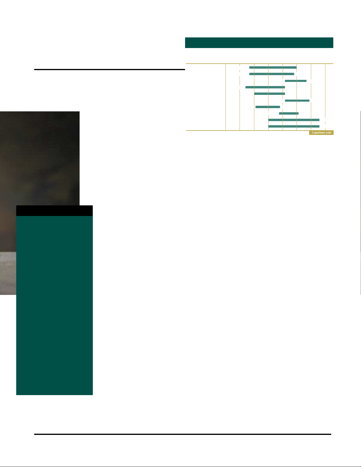
2000 MEASUREMENT RANGE
• DC voltage (0.002%
90-day basic accuracy)
• AC voltage (0.05% 90-day
basic accuracy)
• Two-wire ohms (2WΩ)
• Four-wire ohms (4WΩ)
(0.008% 90-day basic
accuracy)
• DC current
• AC current
• Continuity
• Period
• Frequency
•dB
• dBm
• Temperature (J, K, and
T-type TCs)
• Diode test
• Optional ten-channel
switching
MEASUREMENT FUNCTIONS
1p
1n
1µ
1m
1
1k
1M
6
10
300kHz
500kHz
1G
9
10
100MΩ
100MΩ
DC Voltage
AC Voltage
AC Voltage Bandwidth
DC Current
AC Current
Frequency
Period
Temperature–TC
Resistance (2-wire)
Resistance (4-wire)
–12
–9
–6
–3
0
3A
3A
333ms
3
10
1000V
750V rms
1372°C
10
10
10
10
10
100nV
100nV
3Hz
10nA
1µA
3Hz
2µs
–200°C
100µΩ
100µΩ
Page 6
6
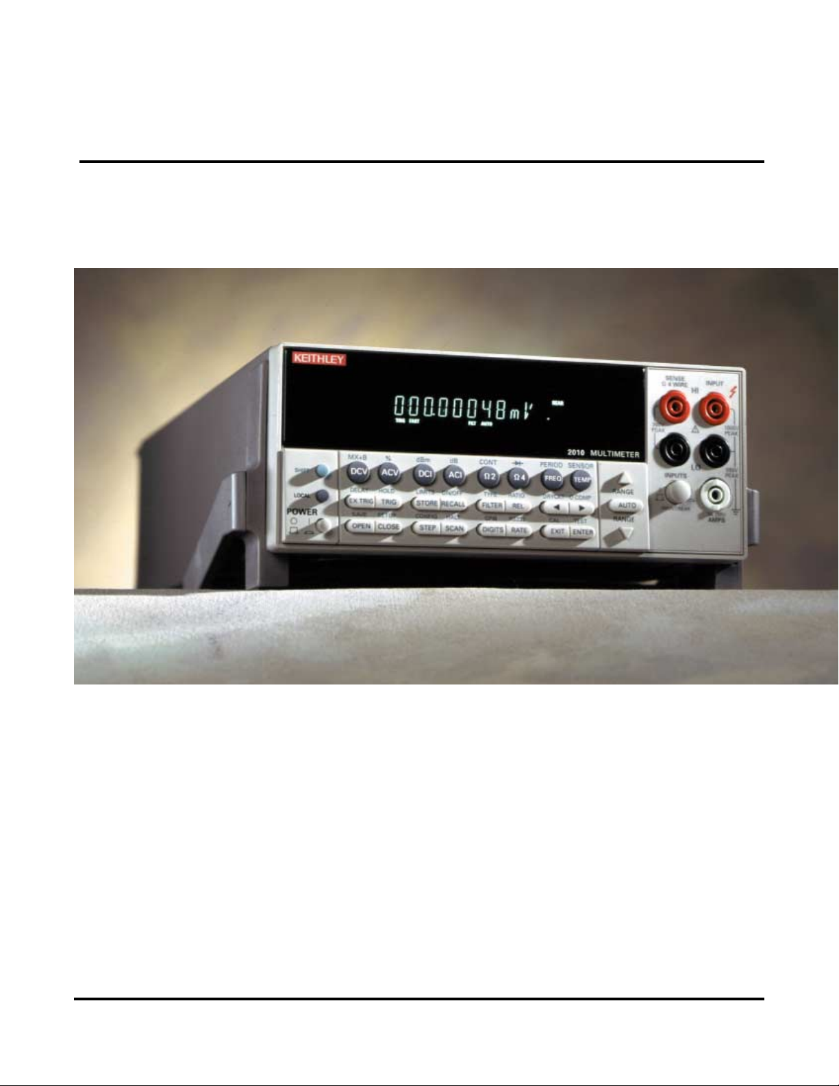
Model 2010 71⁄
2-Digit Multimeter
Low noise DMM with high accuracy
The Low Noise Model 2010 DMM offers production test
system integrators a wide range of advantages, many of them
unavailable even in other Series 2000 meters. The 2010 combines high resolution with the high speed and accuracy needed
for production applications such as testing sensors, transducers,
A/D and D/A converters, regulators, references, connectors,
switches and relays. It’s equally well-suited for testing subassembly or system level electronics.
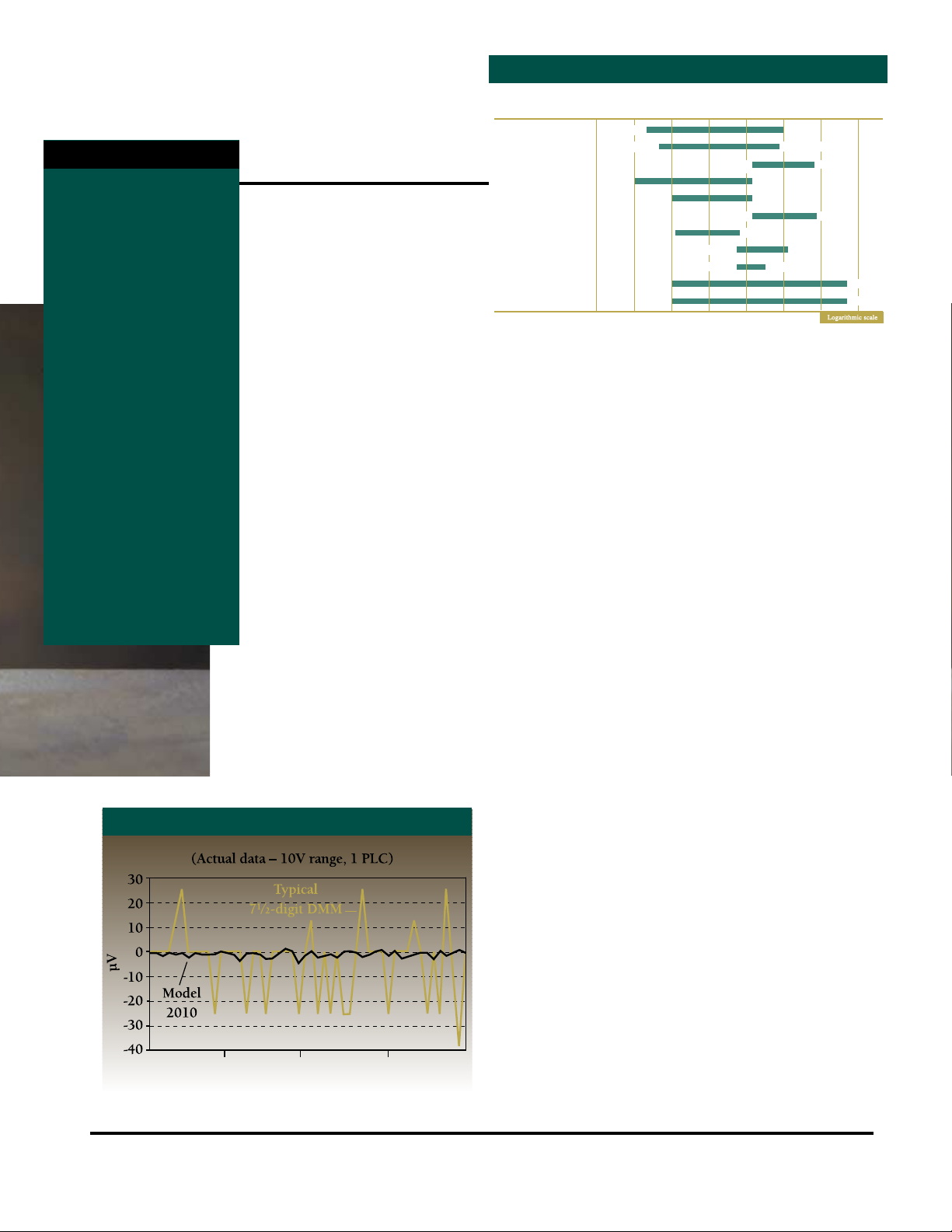
Exceptionally low noise floor
The Model 2010’s low noise floor (just 100nV) allows more
accurate millivolt- and microvolt-level measurements. Additional advantages include high DCV basic accuracy (7ppm),
stability, and linearity (±2ppm of reading + 1ppm of range on
the 10VDC range) to reduce total measurement uncertainty. A
wide dynamic range minimizes range-shift errors and speeds
systems applications by reducing range change delays. The
built-in ratio measurement function simplifies precise relative
measurements and comparison testing. With speeds up to 2000
readings/second, it also provides the high test throughput
required in production applications.
Optimized for ohms measurement
Characterizing the resistance, linearity or isolation of contacts,
connectors, switches or relays completely and efficiently are
common requirements in production testing and demand an
uncommon combination of ohms measurement capabilities. For
example, the 2010 allows making low-level resistance measurements with source current as low as 100µA, an order of
magnitude lower than is possible with other DMMs, so device
self-heating is minimized. Among other benefits, this low-power
ohms measurement capability makes the 2010 suitable for endof-life contact testing per ASTM B539-90.
Page 7
7
When measuring contact and connector resistances, it is critical to control
the test voltage carefully to avoid
puncturing any oxides or films that
may have formed. The Model 2010’s
built-in clamp limits the open circuit
test voltage to 20mV to ensure dry
circuit conditions. An offset compensated ohms function eliminates thermal
effects that can create errors in lowlevel resistance measurements in system environments. The Model 2010’s
extended ohms measurement range allows for more precise measurements
of low resistances.
A variety of built-in math functions
(Rel, Min/Max/A verage/StdDev (of stored
reading), dB, dBm, Limit Test, %, and
mX+b) allow making calculations on
acquired data without a computer. The builtin 10-channel scanner mainframe simplifies
making multi-point measurements—just plug
in an economical switch card.
Simplified software migration
An emulation mode helps preserve your IEEE-488 control
software investment when upgrading a test system by replacing a
Keithley Model 196 or 199 with the Model 2010. The new meter
can be substituted for the old one without software modifications
in most cases. Similarly, if the software was originally developed
for a Model 2000, 2001 or 2002 following SCPI guidelines,
there’s a smooth migration path to the 2010 when the application
demands a different level of resolution or set of functions.
Accessories and companion products
• Model 2000-SCAN: 10-Channel Scanner
• Model 2001-SCAN: 10-Channel Scanner
(with two high-speed channels)
• Model 2001-TCSCAN: 9-Channel Thermocouple
Scanner
• Model 7001: 2-slot Scanner Mainframe
• Model 7002: 10-slot Scanner Mainframe
• More than 40 Series 7000 Switching Cards
• TestPoint®Test Development Software
• Model KPC-488.2 and KPC-488.2AT IEEE-488
Interfaces
Applications
• Millivolt and microvolt output testing
• Drift characterization
• Precision resistance measurement
• Contact resistance, linearity, and isolation testing
• Mixed measurements
• DC voltage (0.0018%
90-day basic accuracy)
• AC voltage (0.05%
90-day basic accuracy)
• Two-wire and four-wire
ohms (10µΩ resolution)
• Dry circuit resistance
measurements
• DC current
• AC current
• Temperature measure-
ments (TCs or RTDs)
• Frequency
• Period
• Ratio
• Continuity measurement
• Diode testing
2010
MEASUREMENT RANGE
MEASUREMENT FUNCTIONS
2010 STABILITY PERFORMANCE
1p
1n
1µ
1m
1
1k
1M
6
10
300kHz
500kHz
1G
9
10
120MΩ
120MΩ
DC Voltage
AC Voltage
AC Voltage Bandwidth
DC Current
AC Current
Frequency
Period
Temperature–TC
Temperature–RTD
Resistance (2-wire)
Resistance (4-wire)
–12
–9
–6
–3
0
10
10
10
10
10nV
100nV
3Hz
1nA
1µA
3Hz
2µs
–200°C
–200°C
1µΩ
1µΩ
10
333ms
3A
3A
10
750V rms
630°C
3
1000V
1372°C
Page 8
8
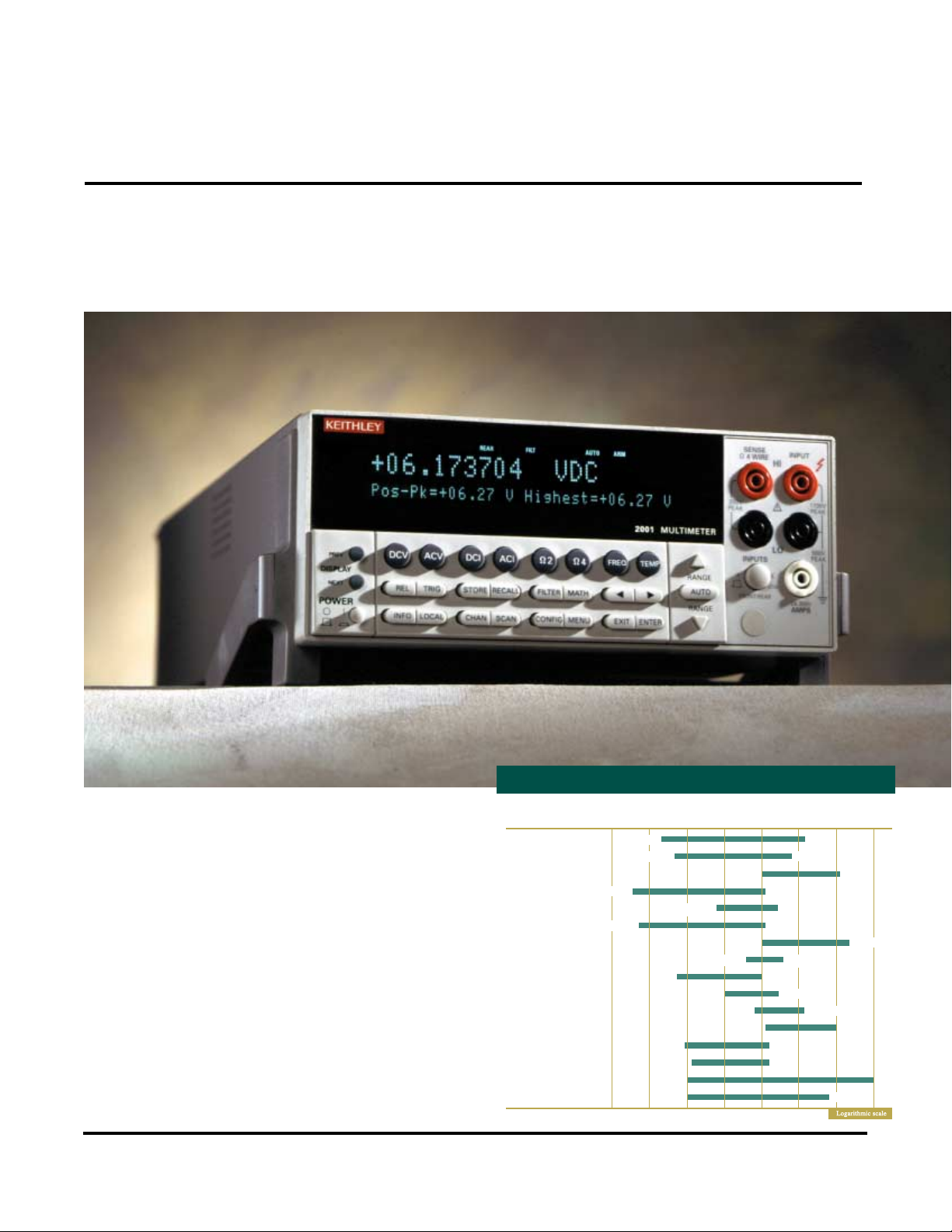
Model 2001 71⁄2-Digit Multimeter
Superior measurement speed and integrity
2001 MEASUREMENT RANGE
In addition to the wide range of measurement functions and
capabilities common to all Series 2000 DMMs, the Model 2001
has many other advantages for test system builders. While other
DMMs may claim to offer 71⁄2
-digit resolution, they typically
must average multiple readings to achieve their specified
resolution, which slows the reading rate significantly. In
contrast, the Model 2001’s true 7
1
⁄2
-digit resolution is based on
a 28-bit A-to-D converter, so no averaging is needed to discern
smaller changes. This high resolution also provides greater
dynamic range, so it’s possible to measure from 1µV to 20V on
a single range and avoid range-shift errors.
Unique measurement capabilities
Unlike the Model 2000 or 2010, the Model 2001 offers the
ability to make peak spikes measurements without the need for
a separate oscilloscope. Its internal peak detector can catch 1µs
spikes, such as power supply spikes and transients, AC line
power surges, and short-duration drop outs on components, as
well as up to 1MHz for repetitive signals. The Model 2001 can
automatically display and store the highest value, or display the
maximum and minimum values of spikes. Similarly, no oscillo-
1p
10
–12
DC Voltage
AC Voltage
AC Voltage Bandwidth
DC Current
DC In-Circuit Current
AC Current
Frequency
Frequency Sensitivity
Period
Temperature–RTD
Temperature–TC
Crest Factor
Peak Spikes–Repetitive
Peak Spikes–Single
Resistance (2-wire)
Resistance (4-wire)
1n
10
–9
1µ
10
–6
1m
10
–3
1
10
0
1k
10
3
1M
10
6
1G
10
9
100nV
1Hz
10pA
100µA
1Hz
60mV
.0001°
1µΩ
1µΩ
1100V
755V rms
2MHz
2.1A
12A
15MHz
775V rms
630°C
1GΩ
210KΩ
10nV
100pA 2.1A
0.1° 1820°C
67ns 1s
20Hz 1MHz
500ns 16s
2µs 16s
Page 9

9
scope is required to determine if the crest factor—the ratio of
peak value to rms values—of an AC signal is acceptable to ensure
measurement accuracy, because the Model 2001 measures AC
crest factor directly.
While some DMMs will calculate average AC
from the RMS value, these calculations apply
only to sine wave inputs. With the Model
2001, it’s easy to measure AC peak value,
average, and true rms directly to characterize
the signal completely. This capability is ideal
for AC circuit design or test, and to verifying
test voltages specified only in averages.
In-circuit current measurement
Unlike voltage and resistance measurements,
which can be made in parallel, measuring current has traditionally required breaking the
conductor to connect the meter in series with
the signal path. However, cutting the circuit,
connecting the meter, making the measure-
ment, then repairing the circuit is
often a tedious, time-consuming
process. The added lead resistance
and voltage burden may also skew
the readings by making the circuit
perform uncharacteristically. The
Model 2001’s in-circuit current
measurement function offers a
convenient, accurate alternative
that eliminates the need to break
the circuit to insert the meter. It
allows taking four readings per
second at 1PLC. Because there is
so little time between measurements, drift effects are almost
zero, for greater measurement
accuracy.
High-speed triggering
Trigger latency—the delay between trigger and measurement—is
often a barrier to higher throughput. The Model 2001 triggers in
less than 2µs ± 1µs—100 to 1000 times faster than other DMMs.
The Trigger-Link feature provides control over six separate
trigger lines for easier system integration and faster operation.
Multiple measurement displays
The Model 2001 can show the results of up to three different
measurements simultaneously on its dual-line display, such as the
DC volts, AC volts and the AC frequency from a single measurement connection. More than 20 multiple-measurement display
combinations can be set, including a bar-graph display that makes
it easy to track meter reading trends around a target value. It can
even be used to replace a nulling differential voltmeter. The bargraph is updated 20 times/second, so it’s useful for monitoring
fast-moving signals.
Dual function option slot
In addition to operating as a 10-channel scanner mainframe, the
Model 2001’s back panel option slot can be used in conjunction
with the optional Model 1801 Nanovolt Pre-Amp for extended
measurement range and sensitivity.
Accessories and companion products
• Model 2000-SCAN: 10-Channel Scanner
• Model 2001-SCAN: 10-Channel Scanner
(with two high-speed channels)
• Model 2001-TCSCAN: 9-Channel Thermocouple Scanner
• Model 1801 Nanovolt Pre-Amp
• Model 7001: 2-slot Scanner Mainframe
• Model 7002: 10-slot Scanner Mainframe
• More than 40 Series 7000 Switching Cards
• TestPoint®Test Development Software
• Model KPC-488.2 and KPC-488.2AT IEEE-488 Interfaces
Applications
• Flexible benchtop testing
• High-speed production testing
• Multipoint scan/measure solution with optional plug-in cards
• DCV
• ACV (peak, avg. and rms)
• AC+DCV (peak, avg. and rms)
• DCI
• AC+DCI (peak, avg. and rms)
• ACI (peak, avg. and rms)
•2WΩ
•4WΩ
• Frequency
• Period
• dB, dBm
• Crest factor measurements
• Peak spikes (high and low)
• Time stamp
• DC in-circuit current
• Temperature (TCs and RTDs)
• Lead resistance
MEASUREMENT FUNCTIONS
Page 10
10
Model 2002 81⁄2-Digit Multimeter
High precision for production test
The Model 2002 81⁄2-Digit Multimeter offers all the capabilities
any system integrator could want when designing a production test
system for high-precision components. It starts with all the capabilities of the Model 2001, then adds an extra decade of resolution
and broader DC voltage, temperature, and resistance measurement
ranges. An “open lead” detection function makes it easy to identify
problems that could lead the system to pass components that
should have failed a test. Built-in digital I/O capabilities and a
pass/fail testing function simplify connecting it to a variety of
handlers for fast, efficient device binning and sorting.
The Model 2002 offers a variety of advantages over other
8
1
⁄2-digit measurement instruments of comparable accuracy,
particularly its DC volts and resistance measurement capabilities. For example, its measurement performance is specified for
a ±5°C environment, not a ± 1°C environment like many others,
and its performance is specified for a wide range of measurement speeds. Also, it does not require a daily re-calibration to
stay in spec. That makes it ideal for high-accuracy production
test applications, because it’s not restricted to the tightly controlled confines of the cal lab, as many other high resolution
DMMs are. And unlike other 81⁄2 -digit meters that must make
4-wire resistance measurements in two phases, the Model 2002
performs them in a single phase, so it can measure twice as fast
for a given power line cycle rate. This one-phase technique also
eliminates errors due to changing lead resistances that can result
from moving test fixtures.
The ability to track reading trends around a target value easily
can be just as important as the accuracy of the absolute readings.
The Model 2002, like the 2001, offers a bar-graph display
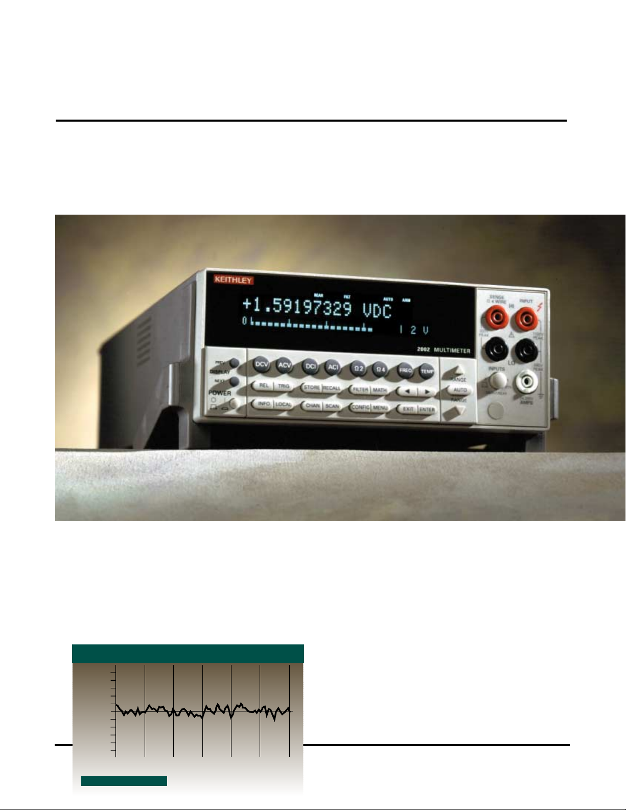
(µV)
0.5
0.4
0.3
0.2
0.1
2002 Stability at 10V
0
-0.1
-0.2
-0.3
-0.4
-0.5
0
50
100
150
200
250
300
Time Sec
2002 STABILITY PERFORMANCE
Model 2002 Stability at 10V
Page 11
11
function that indicates data as a percentage of the selected range
from ±0.01% to ±100%. Whether adjusting about zero or any
other desired value, this display can replace a nulling differential
voltmeter. Two other bar graph displays provide a quick review
of data by clearly showing absolute values or high- low limits.
The bar-graph updates quickly—20 times/
second—so it’s well suited for monitoring
fast-moving signals.
Answers, not just data
Avariety of built-in mathematical calculation
capabilities make it easy to retrieve useful
information directly from the Model 2002,
without the need to transfer raw data to the
computer for analysis. Single measurement
calculation functions available via the front
panel “MATH” key include the measurement
of a value as a percentage of a pre-defined
target and traditional mX+b scaling, which is
often useful in linearizing a sensor’s output.
Statistical calculation can be performed on
a number of buffered sequential
measurements, including the sample’s
arithmetic mean, standard deviation,
as well as maximum and minimum
values. When the two high-speed,
solid-state channels of the Model
2001-SCAN scanner card are used,
the Model 2002 can also calculate
the ratio or compute the difference
between two inputs.
Designed for compatibility
The Model 2002 is also designed to
simplify instrumentation upgrades
and replacements to existing test systems. In addition to compliance with
IEEE-488.2 and SCPI standards, a
built-in language emulation mode
allows the Model 2002 to respond to commands developed for
the HP 3458A DMM, minimizing the need for control program
modifications when upgrading test systems.
Dual function option slot
In addition to operating as a 10-channel scanner mainframe, the
Model 2002’s back panel option slot can be used in conjunction
with the optional Model 1801 Nanovolt Pre-Amp for extended
measurement range and sensitivity.
Accessories and companion products
• Model 2000-SCAN: 10-Channel Scanner
• Model 2001-SCAN: 10-Channel Scanner
(with two high-speed channels)
• Model 2001-TCSCAN: 9-Channel Thermocouple Scanner
• Model 1801 Nanovolt Pre-Amp
• Model 7001: 2-slot Scanner Mainframe
• Model 7002: 10-slot Scanner Mainframe
• More than 40 Series 7000 Switching Cards
• TestPoint
®
Test Development Software
• Model KPC-488.2 and KPC-488.2AT IEEE-488
Interfaces
Applications
• Production testing of precision components such as
resistors, voltage references, D/A and A/D converters
• Design verification
• DCV
• ACV (peak, avg., and rms)
• DCI
• ACI (avg. and rms)
•2WΩ
•4WΩ
• AC+DCV (peak, avg. and rms)
• AC+DCI (peak, avg. and rms)
• Frequency
• Period
• dB, dBm
• Crest factor measurement
• Peak spikes (high and low)
• Time stamp
• DC in-circuit current
• Temperature (TCs and RTDs)
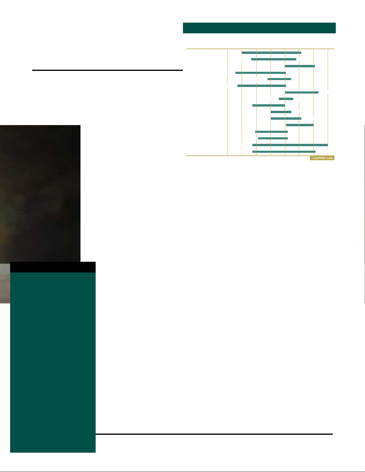
2002 MEASUREMENT RANGE
MEASUREMENT FUNCTIONS
Ω
1n
DC Voltage
AC Voltage
AC Voltage Bandwidth
DC Current
DC In-Circuit Current
AC Current
Frequency
Frequency Sensitivity
Period
Temperature–RTD
Temperature–TC
Crest Factor
Peak Spikes–Repetitive
Peak Spikes–Single
Resistance (2-wire)
Resistance (4-wire)
1p
–12
10
1nV
10pA
100pA 2.1A
1µ
–9
10
100nV
67ns 1s
500ns 16s
2µs 16s
100µΩ
100µΩ
1m
–6
10
–3
10
1Hz
100µA
1Hz
60mV
.0001°
.0001° 1820°C
20Hz 1MHz
1
1k
1M
0
2.1A
12A
630°C
3
10
1100V
755V rms
775V rms
10
10
6
2MHz
15MHz
2.1MΩ
1G
10
9
1G
Page 12
12
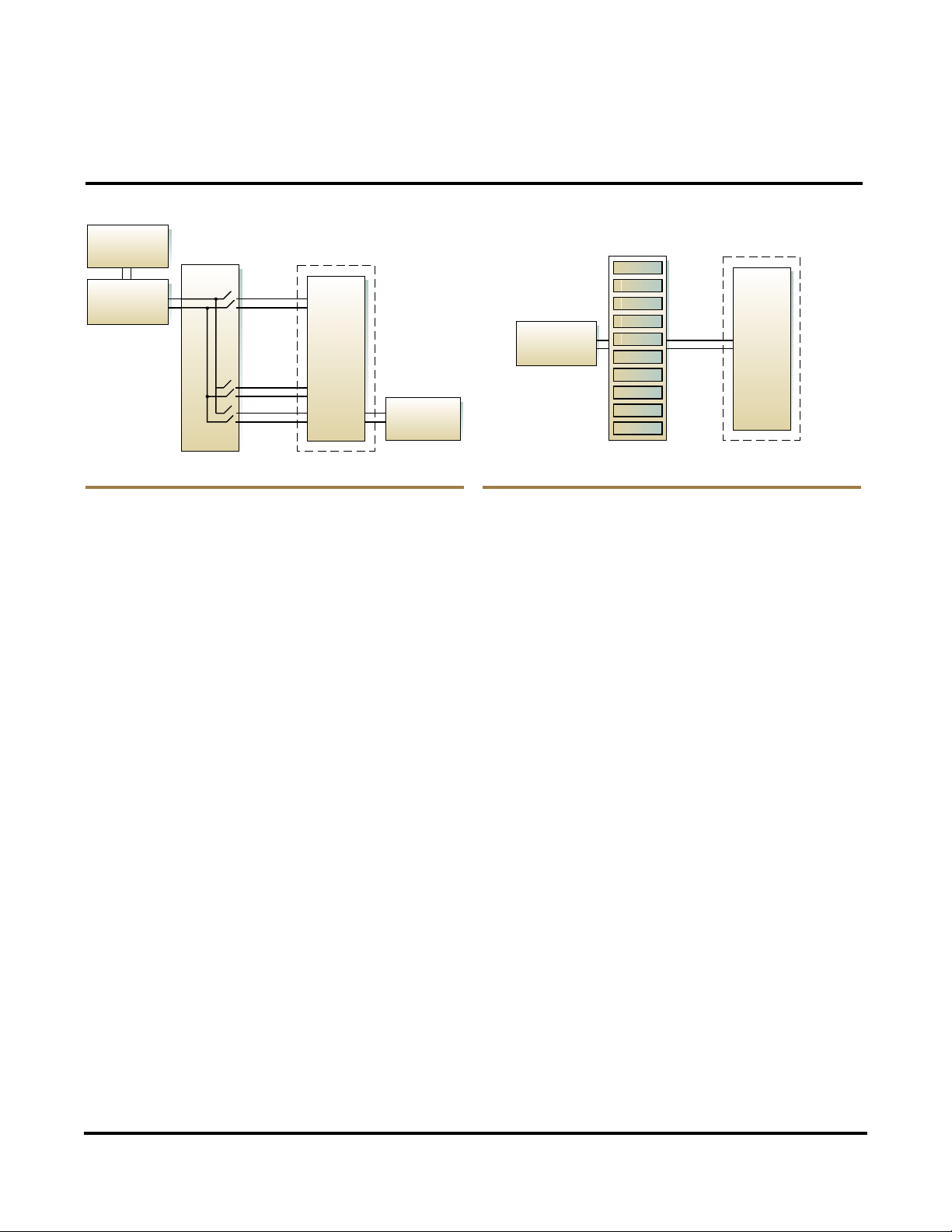
Model 2000 — Automotive radio testing
When used with one of the Series 2000 plug-in scanner cards,
the Model 2000’s unique combination of exceptional measurement speed, accuracy, and low cost make it the basis for an ideal
mini-system for multi-point production testing. Manufacturers
of automotive radios use the Model 2000 in test systems to
make precision DC measurements, audio band AC measurements including amplitude and frequency, as well as measuring
the radio’s temperature during life-cycle environmental testing.
With the addition of a computer controller, power supply and
test fixture, the Model 2000 and the scanner card provide all the
measurement and switching capabilities the application requires.
Model 2010 — Low-level resistance testing
The Model 2010’s unique combination of resistance measurement capabilities makes it particularly useful for low resistance
test applications, such as testing the long-term reliability of
electrical connectors. First, with an ohms measurement range
from 1µ Ω to 120MΩ, the Model 2010 ensures more precise
low-level readings. During production testing of low-ohms
components, device self-heating is kept to a minimum because
resistance measurements can be made with source current as
low as 100µ A, an order of magnitude lower than other DMMs
allow, which ensures more accurate results. This low-power
ohms measurement capability makes the 2010 ideal for end-oflife contact testing per ASTM B539-90.
During resistance testing, precise control of the test voltage is
essential to avoid puncturing any oxides or films that may have
formed on contacts and connectors. With a typical DMM, the
open circuit voltage may rise as high as 5V, destroying the DUT
or invalidating the test. The Model 2010’ s dry circuit test mode
clamps the open circuit voltage at 20mV to prevent these
punctures and ensure the measurement derived reflects the “inuse” resistance. The offset compensated ohms function eliminates thermal effects from cabling and connections that can
introduce errors in low-level resistance measurements.
A Variety of Applications from Engineering…
PC
Controller
Model 2000
DMM
Model
2000-SCAN Card
OUT
ACV
Temperature
DCV
Test Fixture
Device
Under Test
(Radio)
DCV Supply
Model 7002
Switch Mainframe
Connectors
Model 2010
DMM
Up to 10 Model
7011 Switch Cards
(Devices
Under Test)
Environmental
Chamber
Page 13
13
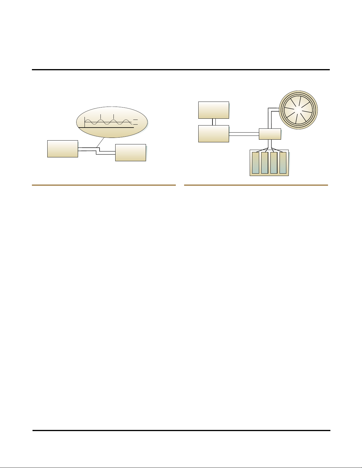
Model 2001— Power supply monitoring
The Model 2001’s multiple display capability makes it easy to
gather several pieces of information simultaneously from
different aspects of a single signal. For example, one of the
Model 2001’s displays is especially well-suited for power
supply monitoring because it shows the DC voltage of the
supply’s output, the AC noise level, and the frequency of that
noise all at once. Displaying the DC voltage and the frequency
of the AC ripple at once makes it simpler to track down the
source of the noise and correct it.
The Model 2001’s Trigger-Link capability is especially useful
for production testing because it acts as a mini trigger controller,
capable of controlling the input and output triggers of up to
three instruments at once. This flexible triggering model,
combined with the Model 2001’s exceptional voltage
measurement capabilities, makes it suitable for building highspeed, high-accuracy test systems, complete with sourcing and
switching hardware.
Model 2002 —
Production testing of precision resistors
The Model 2002’s unique one-phase 4-wire ohms measurement
capability makes it a good choice for applications such as highspeed production testing of precision resistors. T wo high and two
low limits can be tied to the status of any of four protected digital
outputs, so the Model 2002 can be used to sort or grade the resistors automatically after testing. For incoming or outgoing QA
tests on small samples, the front panel bar graph display makes it
easy to determine the tolerances of individual resistors.
…To High-Speed Production Testing
10 KHz
5V 0.1 VAC
Untested Resistors
PC Controller
on Reel
Power Supply
DUT
Model 2001
DMM
Model 2002
DMM
Test Fixture
Devices
Rejected
± .01%
Binning System
± .02%
± .05%
Page 14
14
Choosing the right switching system is often
the key to measurement integrity and high
productivity in production testing for electronic components,
subassemblies, and systems. However, given the limited space
available in many test racks, system builders must find
switching hardware that combines high performance with high
switching density. Keithley’s Applications Engineers can help
you determine the most appropriate switching configuration
for your testing application.
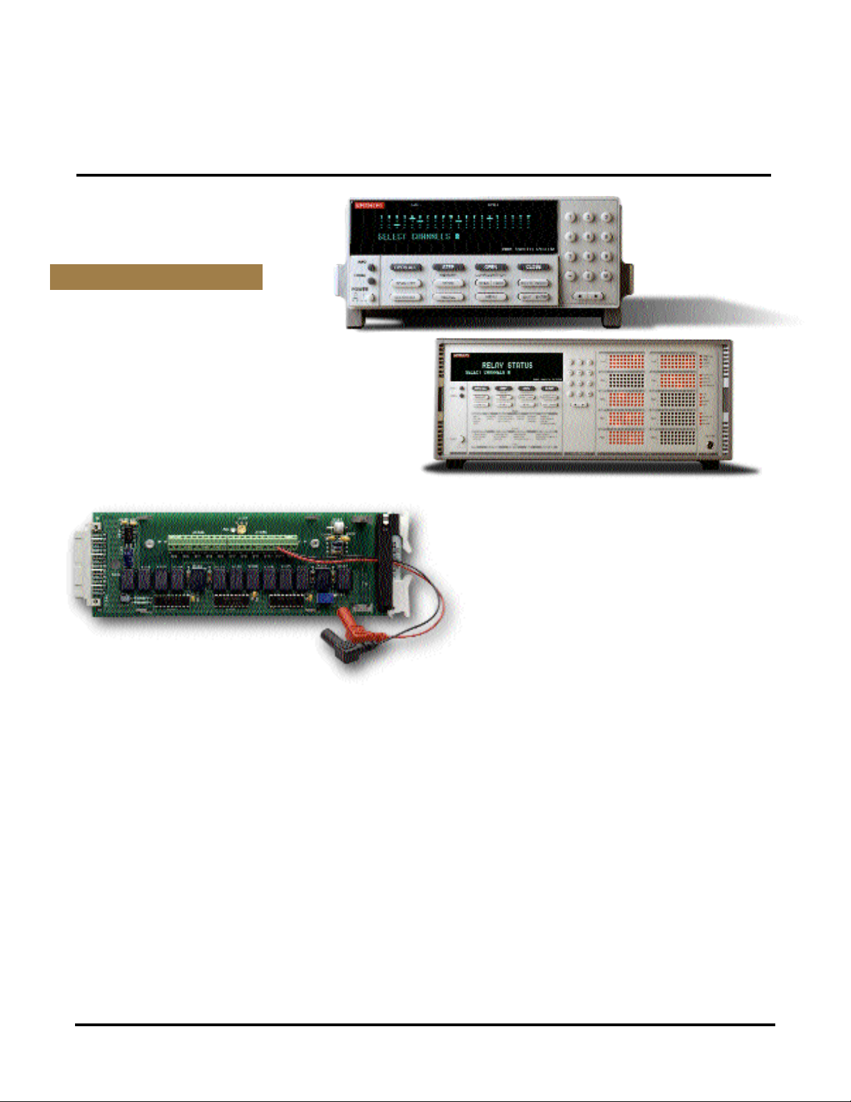
Plug-in Scanner Cards
Three plug-in scanner cards have been
designed specifically for use with Series 2000 DMMs. To create
a multipoint test and measurement system that’s well suited to
applications involving up to ten measurement points, simply
insert the appropriate card in the option slot on the DMM’s back
panel. Combining scan and measure capabilities in a single
instrument reduces the need for extra equipment, eliminates
complexities of triggering, timing and processing issues, and
reduces test time significantly.
Model 7001 80-Channel or
Model 7002 400-Channel Switch System
The 7001 and 7002 complement Series 2000 DMMs when
building multi-point test systems, such as those for testing
battery-powered portable devices like pagers and cellular
phones. The Model 7001 High Density Switch System takes
up only a half-rack space and has two slots that will accept
a wide variety of switching cards for signals up to 1.8 GHz. It
supports twice as many channels (80) in half the space of typical
switching systems. Similarly, the ten-slot Model 7002 Switch
Mainframe will support up to 400 2-pole multiplexer channels
or 400 matrix crosspoints, with a unique interactive front panel
channel status display. Both mainframes are compatible with
more than 40 Keithley switching cards, including many types of
multiplexer, matrix, multi-channel relay, thermocouple, scanner,
universal adapter, and RF cards.
Building Blocks for a Comprehensive Test System Solution
S
IGNAL SWITCHING OPTIONS
Page 15
15
Model KPC-288.2 and KPC-488.2AT GPIB
Interfaces
These interface boards are designed to simplify building PCcontrolled test systems. Both boards are compatible with all
IEEE-488 instruments, including those that use Standard Commands for Programmable Instruments.
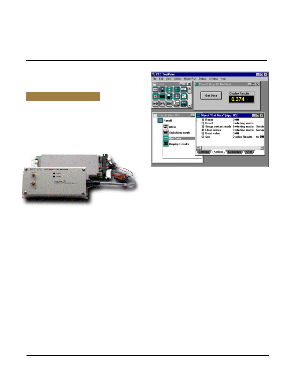
Model 1801 Nanovolt Pre-Amp
The Model 1801 amplifies extremely low-level signals,
extending the range and sensitivity of Model 2001 and 2002
DMMs. It combines a variety of measurement functions,
including DCV, ACV rms, 4-wire ohms, frequency, and temperature. The remote preamp architecture isolates the Model 1801’ s
sensitive “chopper-type” amplification circuitry, allowing users
to locate the unit close to the test set-up and keep test leads
short, reducing interference. Anine-foot cable links the pre-amp
unit to a power supply card, which installs in the DMM’s back
panel option slot.
TestPoint®Test Development Software
TestPoint is a multi-tasking, object-oriented software package
that simplifies creating custom test, measurement and data
acquisition applications in the Microsoft Windows®environment
without using conventional programming techniques. It’s the
only applications development package that combines IEEE-488,
RS-232, and RS-485 instrument control capabilities with support
for a broad range of data acquisition boards. More than 240
Instrument Driver Libraries simplify control of a wide range of
instruments, including the Series 2000 DMMs. TestPoint also
offers wide flexibility, providing full access to external subroutines written using conventional programming languages.
Building Blocks for a Comprehensive Test System Solution
EXTENDED SYSTEM CAPABILITIES
Page 16

16
ACCURACY
INPUT ± (ppm of reading + ppm of range)
RANGE RESOLUTION RESISTANCE 24 Hours 90 Days 1 Year
100.0000 mV 0.1 µV >10 GΩ 30 + 30 40 + 35 50 + 35
1.000000 V 1.0 µV >10 GΩ 15 + 6 25 + 7 30 + 7
10.00000 V 10 µV >10 GΩ 15 + 4 20 + 5 30 + 5
100.0000 V 100 µV 10 MΩ 15 + 6 30 + 6 45 + 6
1000.000 V 1 mV 10 MΩ 20 + 6 35 + 6 45 + 6
(TRMS), Max. 5:1 crest factor at full scale for inputs > 5% of range. Accuracy: ±(% of reading + % of range),
1 Year, 23°C ± 5°C (all ranges)
RANGE RESOLUTION 3Hz–10Hz 10Hz–20kHz 20kHz–50kHz 50kHz–100kHz 100kHz–300kHz
200 mV 0.1 µV 0.35 + 0.03 0.06 + 0.03 0.11 + 0.05 0.6 + 0.08 4 + 0.5
2 V 1 µV 0.35 + 0.03 0.06 + 0.03 0.11 + 0.05 0.6 + 0.08 4 + 0.5
20 V 10 µV 0.35 + 0.03 0.06 + 0.03 0.11 + 0.05 0.6 + 0.08 4 + 0.5
200 V 100 µV 0.35 + 0.03 0.06 + 0.03 0.12 + 0.05 0.6 + 0.08 4 + 0.5
750 V 1 mV 0.35 + 0.03 0.06 + 0.03 0.12 + 0.05 0.6 + 0.08 4 + 0.5
ACCURACY
± (ppm of reading + ppm of range)
RANGE RESOLUTION TEST CURRENT 24 Hours 90 Days 1 Year
100.0000 Ω 100 µΩ 1 mA 30 + 30 80 + 40 100 + 40
1.000000 kΩ 1mΩ 1 mA 20 + 6 80 + 10 100 + 10
10.00000 kΩ 10 mΩ 100 µA 20 + 6 80 + 10 100 + 10
100.0000 kΩ 100 mΩ 10 µA 20 + 6 80 + 10 100 + 10
1.000000 MΩ 1 Ω 10 µA 20 + 6 80 + 10 100 + 10
10.00000 MΩ 10 Ω 700 nA 150 + 6 200 + 10 400 + 10
100.0000 MΩ 100 Ω 700 nA 800 + 30 1500 + 30 1500 + 30
ACCURACY
MAX. BURDEN ± (ppm of reading + ppm of range)
RANGE RESOLUTION VOLTAGE 24 Hours 90 Days 1 Year
10 mA 10 nA < 0.15 V 60 + 15 300 + 40 500 + 40
100 mA 100 nA < 0.03 V 100 + 50 300 + 400 500 + 400
1 A 1 µA < 0.3 V 200 + 15 500 + 40 800 + 40
3 A 10 µA < 1 V 1000 + 10 1200 + 15 1200 + 15
(TRMS), Max. 5:1 crest factor at full scale for inputs > 5% of range. Accuracy: ±(% of reading + % of range) ,
1 Year, 23°C ± 5°C (all ranges)
RANGE RESOLUTION 3Hz–10kHz 10Hz–5kHz
1.000000 mV 1 µV 0.30 + 0.04 0.10 + 0.04
3.000000 V 10 µV 0.35 + 0.06 0.15 + 0.06
RANGE TEST CURRENT
3V 1m A
10V 10 µA, 100 µA
ACCURACY
ACV FREQUENCY PERIOD RESOLUTION (90 Day to 1 Year)
RANGE RANGE RANGE ± (ppm of rdg.) ± (ppm of rdg.)
100 mV 3 Hz 333 ms
to to to 0.3 0.01
750 v 300 kHz 2 µs
TYPE RANGE RESOLUTION ACCURACY
(using 2001-TSCAN)
J -200° C to +760°C 0.001°C ± 0.65°C
K -200° C to +1372°C 0.001°C ± 0.70°C
T -200° C to +400°C 0.001°C ± 0.68°C
2000 Condensed Specifications
DC V
OLTS
AC VOLTS
ACCURACY
RESISTANCE
DC CURRENT
AC CURRENT
FREQUENCY AND PERIOD
TEMPERATURE (THERMOCOUPLE)
DIODE TEST GENERAL INFORMATION
MATH FUNCTIONS:
Null, Limit, and Min/Max/Avg/Std Dev of stored readings
DATA STORAGE:
Selectable up to 1024 readings max.
STANDARD PROGRAMMING LANGUAGES:
SCPI, Fluke 8840A/8842A, Keithley
199/196.
INTERFACES:
IEEE-488 and RS-232.
POWER SUPPLY:
100V / 120V / 220V / 240V.
LINE FREQUENCY:
45Hz to 66Hz and 360Hz to 400Hz.
POWER CONSUMPTION:
22VA.
OPERATING ENVIRONMENT:
Specified for 0°C to 50°C
Specified to 80% R.H. at 35°C
STORAGE ENVIRONMENT:
-40°C to 70°C.
WARRANTY:
3 years.
PHYSICAL:
Case Dimensions: 89mm × 213mm wide × 370mm deep.
(31⁄
2 in × 8
3
⁄
8 in × 14
9
⁄
16 in).
Unit Weight: 2.9kg (6 lbs 3 oz).
STANDARDS:
Safety: Designed to CSA, UL-1244, IEC-1010.
EMI: Conforms to VDE 0871B (per Vfg 1046/1984).
Meets FCC part 15 class B. Conforms to CISPR22, EN-5504.
ESD: Conforms to IEC-801-2.
Page 17

17
ACCURACY
INPUT ± (ppm of reading + ppm of range)
RANGE RESOLUTION RESISTANCE 24 Hours 90 Days 1 Year 2 Years
100.00000 mV 10 nV >10 GΩ 10 + 9 25 + 9 37 + 9 50 + 10
1.0000000 V 100 nV >10 GΩ 7 + 2 18 + 2 25 + 2 32 + 2
10.000000 V 1 µV >10 GΩ 7 + 4 18 + 4 24 + 4 32 + 4
100.00000 V 10 µV 10 MΩ 10 + 4 25 + 5 35 + 6 52 + 5
1000.0000 V 100 µV 10 MΩ 17 + 6 31 + 6 41 + 6 55 + 6
(TRMS), Max. 5:1 crest factor at full scale for inputs > 5% of range. Accuracy: ±(% of reading + % of range),
1 Year, 23°C ± 5°C (all ranges)
RANGE RESOLUTION 3Hz–10Hz 10Hz–20kHz 20kHz–50kHz 50kHz–100kHz 100kHz–300kHz
200 mV 0.1 µV 0.35 + 0.03 0.06 + 0.03 0.11 + 0.05 0.6 + 0.08 4 + 0.5
2 V 1 µV 0.35 + 0.03 0.06 + 0.03 0.11 + 0.05 0.6 + 0.08 4 + 0.5
20 V 10 µV 0.35 + 0.03 0.06 + 0.03 0.11 + 0.05 0.6 + 0.08 4 + 0.5
200 V 100 µV 0.35 + 0.03 0.06 + 0.03 0.12 + 0.05 0.6 + 0.08 4 + 0.5
750 V 1 mV 0.35 + 0.03 0.06 + 0.03 0.12 + 0.05 0.6 + 0.08 4 + 0.5
ACCURACY
TEST ± (ppm of reading + ppm of range)
RANGE RESOLUTION CURRENT 24 Hours 90 Days 1 Year 2 Years
10.000000 Ω 1µΩ 10 mA 15 + 9 40 + 9 60 + 9 100 + 10
100.00000 Ω 10 µΩ 1 mA 15 + 9 36 + 9 52 + 9 90 + 10
1.0000000 kΩ 100 mΩ 1 mA 15 + 2 33 + 2 50 + 2 80 + 2
10.000000 kΩ 1mΩ 100 µA 15 + 2 32 + 2 50 + 2 80 + 2
100.00000 kΩ 10 mΩ 10 µA 15 + 2 40 + 2 70 + 2 120 + 2
1.0000000 MΩ 100 mΩ 10 µA 20 + 3 50 + 4 70 + 4 125 + 4
10.000000 MΩ 1 Ω 640 nA // 10MΩ 150 + 2 200 + 4 400 + 4 500 + 4
100.00000 MΩ 10 Ω 640 nA // 10MΩ 800 + 4 1500 + 4 1500 + 4 1800 + 4
10.000000 Dry Circuit 10 µΩ 1 mA / 20 mV max. 25 + 90 50 + 90 70 + 90 120 + 90
100.00000 Dry Circuit 100 µΩ 100 µA / 20 mV max. 25 + 90 50 + 90 70 + 90 120 + 90
ACCURACY
MAX. BURDEN ± (ppm of reading + ppm of range)
RANGE RESOLUTION VOLTAGE 24 Hours 90 Days 1 Year 2 Years
10.000000 mA 1 nA < 0.15 V 60 + 15 300 + 40 500 + 40 740 + 40
100.00000 mA 10 nA < 0.18 V 100 + 15 300 + 40 500 + 40 740 + 40
1.0000000 A 100 nA < 0.35 V 200 + 15 500 + 40 800 + 40 1200 + 40
3.000000 A 1 µA < 1 V 1000 + 10 1200 + 15 1200 + 15 1800 + 15
(TRMS), Max. 5:1 crest factor at full scale for inputs > 5% of range. Accuracy: ±(% of reading + % of range),
1 Year, 23°C ± 5°C (all ranges)
RANGE RESOLUTION 3Hz –10Hz 10Hz–5kHz
1.000000 mV 1 µV 0.30 + 0.04 0.10 + 0.04
3.000000 V 10 µV 0.35 + 0.06 0.15 + 0.06
ACCURACY
ACV FREQ. PERIOD GATE RESOLUTION (90 Day to 1 Year)
RANGE RANGE RANGE TIME ± (ppm of rdg.) ± (ppm of rdg.)
100 mV 3 Hz 333 ms
to to to 1 s 0.3 0.01
750 v 500 kHz 2 µs
RATE DIGITS 10 sec. 2 min. 10 sec. 2 min. NMRR CMRR
5 PLC 7
1
⁄2 100 nV 110 nV 1.1 µV 1.2 µV 60 dB 140 dB
5 PLC 6
1
⁄2 120 nV 125 nV 1.3 µV 1.4 µV 60 dB 140 dB
0.1 PLC 5
1
⁄
2 1.5 µV 1.6 µV 11 µ V 11.5 µV — 80 dB
0.1 PLC 4
1
⁄
2 3.0 µV 2.9 µV 135 µV 139 µ V — 80 dB
2010 Condensed Specifications
DC V
OLTS
AC VOLTS
ACCURACY
RESISTANCE
DC C
URRENT
AC CURRENT
FREQUENCY AND PERIOD CHARACTERISTICS
DC NOISE PERFORMANCE
G
ENERAL INFORMATION
POWER SUPPLY:
100V / 120V / 220V / 240V ±10%.
LINE FREQUENCY:
45Hz to 66Hz and 360Hz to 400Hz,
automatically sensed at power-up.
POWER CONSUMPTION:
22VA.
OPERATING ENVIRONMENT:
Specified for 0°C to 50°C.
Specified to 80% R.H. at 35°C
STORAGE ENVIRONMENT:
-40°C to 70°C.
WARRANTY:
3 years.
SAFETY:
Designed to UL-3111-1, IEC-1010-1.
EMC:
Complies with European Union Directive 89/336/EEC (CE marking requirements),
FCC part 15 class B, CTSPR 11, IEC 801-2, IEC 801-3, IEC 801-4.
VIBRATION:
MIL-T-28800E Type III, Class 5.
WARMUP:
2 hours to rated accuracy.
Page 18

18
ACCURACY
DEFAULT INPUT ± (ppm of reading + ppm of range)
RANGE FULL SCALE RESOLUTION RESOLUTION RESISTANCE 5 Minutes 24 Hours 90 Days 1 Year 2 Years
200 mV ±210.00000 10 nV 100 nV >10 GΩ 3 + 3 10 + 6 25 + 6 37 + 6 50 + 6
2 V ±2.1000000 100 nV 1 µV >10 GΩ 2 + 1.5 7 + 2 18 + 2 25 + 2 32 + 2
20 V ±21.000000 1 µV 10 µV >10 GΩ 2 + 1.5 7 + 4 18 + 4 24 + 4 32 + 4
200 V ±210.00000 10 µV 100 µV 10 MΩ ±1% 2 + 1.5 13 + 3 27 + 3 38 + 3 52 + 3
1000 V ±1100.0000 100 µ V 1 mV 10 MΩ ±1% 10 + 1.5 17 + 6 31 + 6 41 + 6 55 + 6
(Normal Mode–TRMS), Low Freq. mode extends down to 1Hz; Peak AC, dB, AC+DC modes also included.
90 Days, ±2°C from last AC self-cal for 1% to 100% of range ±(% of reading + % of range)
RANGE 20–50Hz 50–100Hz 0.1–2kHz 2–10kHz 10–30kHz 30–50kHz 50–100kHz 100–200kHz 0.2–1MHz 1–2MHz
200 mV 0.25 + 0.015 0.07 + 0.015 0.03 + 0.015 0.03 + 0.015 0.035 + 0.015 0.05 + 0.015 0.17 + 0.015 0.5 + 0.025 2 + 0.1 5 + 0.2
2 V 0.25 + 0.015 0.07 + 0.015 0.03 + 0.015 0.03 + 0.015 0.035 + 0.015 0.05 + 0.015 0.17 + 0.015 0.5 + 0.025 2 + 0.1 5 + 0.2
20 V 0.25 + 0.015 0.07 + 0.015 0.04 + 0.015 0.06 + 0.015 0.08 + 0.015 0.1 + 0.015 0.17 + 0.015 0.5 + 0.025 4 + 0.2 7 + 0.2
200 V 0.25 + 0.015 0.07 + 0.015 0.04 + 0.015 0.06 + 0.015 0.08 + 0.015 0.1 + 0.015 0.17 + 0.015 0.5 + 0.025 4 + 0.2
750 V 0.25 + 0.015 0.1 + 0.015 0.08 + 0.015 0.09 + 0.015 0.12 + 0.015 0.15 + 0.015 0.5 + 0.015
ACCURACY
CURRENT ± (ppm of reading + ppm of range)
RANGE FULL SCALE RESOLUTION SOURCE 24 Hours 90 Days 1 Year 2 Years
20 Ω 21.000000 1 µΩ 9.2 mA 29 + 7 52 + 7 72 + 7 110 + 7
200 Ω 210.00000 10 µΩ 0.98 mA 24 + 7 36 + 7 56 + 7 90 + 7
2kΩ 2100.0000 100 µΩ 0.98 mA 22 + 4 33 + 4 50 + 4 80 + 4.5
20 kΩ 21.000000 1 mΩ 89 µA 19 + 4 32 + 4 50 + 4 80 + 4.5
200 kΩ 210.00000 10 mΩ 7 µA 20 + 4.5 72 + 4.5 90 + 4.5 130 + 5
2MΩ 2.1000000 100 mΩ 770 nA 50 + 4.5 110 + 4.5 160 + 4.5 230 + 5
20 MΩ 21.000000 1 Ω 70 nA 160 + 4.5 560 + 4.5 900 + 4.5 1100 + 5
200 MΩ 210.00000 10 Ω 4.4 nA 3000 + 100 10000 + 100 20000 +100 30000 +100
1GΩ 1.0500000 100 Ω 4.4 nA 9000 + 100 20000 + 100 40000 + 100 60000 +100
ACCURACY
MAXIMUM BURDEN ± (ppm of reading + ppm of range)
RANGE FULL SCALE RESOLUTION VOLTAGE 24 Hours 90 Days 1 Year 2 Years
200 µA 210.00000 10 pA 0.25 V 63 + 25 300 + 25 500 + 25 1350 + 25
2 mA 2.1000000 100 pA 0.31 V 64 + 20 300 + 20 400 + 20 750 + 20
20 mA 21.000000 1 nA 0.4 V 65 + 20 300 + 20 400 + 20 750 + 20
200 mA 210.00000 10 nA 0.5 V 96 + 20 300 + 20 500 + 20 750 + 20
2 A 2.1000000 100 nA 1.5 V 500 + 20 600 + 20 900 + 20 1350 + 20
90 Days, 1 Year or 2 Years, TCAL ±5°C, for 5% to 100% of range, ± % of reading + % of range)
RANGE 20Hz – 50Hz 50Hz – 200Hz 200Hz – 1kHz 1kHz – 10kHz 10kHz – 30kHz 30kHz – 50kHz 50kHz – 100kHz
200 µA 0.35 + 0.015 0.2 + 0.015 0.4 + 0.015 0.5 + 0.015
2 mA 0.3 + 0.015 0.15 + 0.015 0.12 + 0.015 0.12 + 0.015 0.25 + 0.015 0.3 + 0.015 0.5 + 0.015
20 mA 0.2 + 0.015 0.15 + 0.015 0.12 + 0.015 0.12 + 0.015 0.25 + 0.015 0.3 + 0.015 0.5 + 0.015
200 mA 0.3 + 0.015 0.15 + 0.015 0.12 + 0.015 0.15 + 0.015 0.5 + 0.015 1 + 0.015 3 + 0.015
2 A 0.35 + 0.015 0.2 + 0.015 0.3 + 0.015 0.45 + 0.015 1.5 + 0.015 4 + 0.015
RANGE: 1Hz–15MHz.
ACCURACY: ±(0.03% of reading).
RANGE: 100µA to 12A.
ACCURACY: ±(5% + 2 counts) over 2 years.
TRACE RESISTANCE: 1mΩto 10Ω typical.
Built-in linearization for J, K, T, E, R, S, B thermocouple types
and 100Ω platinum RTDs DIN 43760 or IPTS-68.
For complete specifications, reference the 2001 Technical Data Book.
2001 Condensed Specifications
DC V
OLTS
AC VOLTS
ACCURACY
RESISTANCE
DC A
MPS
AC AMPS ACCURACY
FREQUENCY COUNTER
GENERAL/STANDARDS COMPLIANCE
DC IN-CIRCUIT CURRENT
TEMPERATURE
POWER
Voltage: 90–134Vand 180–264V, universal self-selecting.
Frequency: 50Hz, 60Hz, or 400Hz self-identifying.
Consumption: <55 VA.
ENVIRONMENT
Operating Temperature: 0°to 50°C.
Storage Temperature: –40°to +70°C.
Humidity: 80% R.H., 0° to 35°C.
Altitude: 4,500m (15,000 ft) operating; 12,000m (40,000 ft.) non-operating.
PHYSICAL
Case Dimensions: 90mm high × 214mm wide × 369mm deep (31⁄
2 in × 8
1
⁄
2 in × 14
1
⁄
2 in).
Unit Weight: 4.2kg (9 lbs 3 oz).
STANDARDS
EMI/RFI: Conforms to VDE 0871B (per Vfg 1046/1984),IEC 801-2, FCC part 15 Class B, CISPR-22
(EN55022).
Safety: Conforms to IEC348, CAN/CSA-C22.2 No. 231, MIL-T-28800E1. Designed to UL1244.
Page 19

19
ACCURACY
INPUT ± (ppm of reading + ppm of range)
RANGE FULL SCALE RESOLUTION RESISTANCE Transfer 24 Hours 90 Days 1 Year 2 Years
200 mV ±210.000000 1 nV >100 GΩ 0.4 + 1.5 3.5 + 3 15 + 8 19 + 9 23 + 10
2 V ±2.10000000 10 nV >100 GΩ 0.2 + 0.15 1.2 + 0.3 6 + 0.8 10 + 0.9 14 + 1
20 V ±21.0000000 100 nV >100 GΩ 0.1 + 0.05 1.2 + 0.1 6 + 0.15 10 + 0.15 14 + 0.15
200 V ±210.000000 1 µV 10 MΩ ±1% 0.5 + 0.08 5 + 0.4 14 + 2 22 + 2 30 + 2
1000 V ±1100.00000 10 µV 10 MΩ ±1% 1 + 0.05 5 + 0.08 14 + 0.4 22 + 0.4 30 + 0.4
(Normal Mode–TRMS), Low Freq. mode extends down to 1Hz; Peak AC, dB, AC+DC modes also included.
90 Days, 1 Year or 2 Years, ±2°C from last AC self-cal for 1% to 100% of range, ±(% of reading + % of range)
RANGE 20–50Hz 50–100Hz 0.1–2kHz 2–10kHz 10–30kHz 30–50kHz 50–100kHz 100–200kHz 0.2–1MHz 1–2MHz
200 mV 0.25 + 0.015 0.07 + 0.015 0.02+ 0.01 0.02 + 0.01 0.025 + 0.01 0.05 + 0.01 0.17 + 0.015 0.5 + 0.025 2 + 0.1 5 + 0.2
2 V 0.25 + 0.015 0.07 + 0.015 0.02 + 0.01 0.02 + 0.01 0.025 + 0.01 0.05 + 0.01 0.17 + 0.015 0.5 + 0.025 2 + 0.1 5 + 0.2
20 V 0.25 + 0.015 0.07 + 0.015 0.03 + 0.015 0.04 + 0.015 0.05 + 0.015 0.07 + 0.015 0.17 + 0.015 0.5 + 0.025 4 + 0.2 7 + 0.2
200 V 0.25 + 0.015 0.07 + 0.015 0.03 + 0.015 0.04 + 0.015 0.05 + 0.015 0.07 + 0.015 0.17 + 0.015 0.5 + 0.025 4 + 0.2
750 V 0.25 + 0.015 0.1 + 0.015 0.05 + 0.015 0.06 + 0.015 0.08 + 0.015 0.1 + 0.015 0.5 + 0.015
ACCURACY
CURRENT ± (ppm of reading + ppm of range)
RANGE FULLSCALE RESOLUTION SOURCE Transfer 24 Hours 90 Days 1 Year 2 Years
20 Ω 21.0000000 100 nΩ 7.2 mA 2.5 + 3 5 + 4.5 15 + 6 17 + 6 20 + 6
200 Ω 210.000000 1 µΩ 960 µA 2.5 + 2 5 + 3 15 + 4 17 + 4 20 + 4
2kΩ 2100.00000 10 µΩ 960 µA 1.3 + 0.2 2.5 + 0.3 7 + 0.4 9 + 0.4 11 + 0.4
20 kΩ 21.0000000 100 µΩ 96 µA 1.3 + 0.2 2.5 + 0.3 7 + 0.4 9 + 0.4 11 + 0.4
200 kΩ 210.000000 1 mΩ 9.6 µA 2.5 + 0.4 4.5 + 0.5 17 + 0.8 21 + 0.9 25 + 1
2MΩ 2.10000000 10 mΩ 1.9 µA 5 + 0.2 10 + 0.3 38 + 0.5 50 + 0.5 62 + 0.5
20 MΩ 21.0000000 100 mΩ 1.4 µA 15 + 0.1 50 + 0.2 175 + 0.6 250 + 0.6 300 + 0.6
200 MΩ 210.000000 1 Ω 1.4 µA 50 + 0.5 150 + 1 500 + 3 550 + 3 600 + 3
1GΩ 1.05000000 10 Ω 1.4 µA 250 + 2.5 750 + 5 2000 + 15 2050 + 15 2100 + 15
ACCURACY
MAXIMUM BURDEN ± (ppm of reading + ppm of range)
RANGE FULL SCALE RESOLUTION VOLTAGE 24 Hours 90 Days 1 Year 2 Years
200 µA 210.00000 10 pA 0.25 V 50 + 6 275 + 25 350 + 25 500 + 25
2 mA 2.1000000 100 pA 0.3 V 50 + 5 275 + 20 350 + 20 500 + 20
20 mA 21.000000 1 nA 0.35 V 50 + 5 275 + 20 350 + 20 500 + 20
200 mA 210.00000 10 nA 0.35 V 75 + 5 300 + 20 375 + 20 525 + 20
2 A 2.1000000 100 nA 1.1 V 350 + 5 600 + 20 750 + 20 1000 + 20
90 Days, 1 Year or 2 Years, TCAL ±5°C, for 5% to 100% of range, ± % of reading + % of range)
RANGE 20Hz – 50Hz 50Hz – 200Hz 200Hz – 1kHz 1kHz – 10kHz 10kHz – 30kHz 30kHz – 50kHz 50kHz – 100kHz
200 µA 0.35 + 0.015 0.2 + 0.015 0.4 + 0.015 0.5 + 0.015
2 mA 0.3 + 0.015 0.15 + 0.015 0.12 + 0.015 0.12 + 0.015 0.25 + 0.015 0.3 + 0.015 0.5 + 0.015
20 mA 0.3 + 0.015 0.15 + 0.015 0.12 + 0.015 0.12 + 0.015 0.25 + 0.015 0.3 + 0.015 0.5 + 0.015
200 mA 0.3 + 0.015 0.15 + 0.015 0.12 + 0.015 0.15 + 0.015 0.5 + 0.015 1 + 0.015 3 + 0.015
2 A 0.35 + 0.015 0.2 + 0.015 0.3 + 0.015 0.45 + 0.015 1.5 + 0.015 4 + 0.015
RANGE: 1Hz–15MHz.
ACCURACY: ± (0.03% of reading)
RANGE: 100µA to 12A.
ACCURACY: ± (5% + 500µA), 1 year or 2 years.
TRACE RESISTANCE: 1mΩto 10Ω.
Built-in linearization for J, K, T, E, R, S, B thermocouple types and
100Ω platinum RTDs DIN43760, IPTS-68, and ITS-90.
For complete specifications, reference the 2002 Technical Data Book.
2002 Condensed Specifications
DC V
OLTS
10
PLC,
D
FILT
10
AC VOLTS
ACCURACY
RESISTANCE
10
PLC, OFFSET COMP D
FILT
10
DC A
MPS
AC AMPS ACCURACY
FREQUENCY COUNTER
GENERAL/STANDARDS COMPLIANCE
DC IN-CIRCUIT CURRENT
TEMPERATURE
POWER
Voltage: 90–134Vand 180–264V, universal self-selecting.
Frequency: 50Hz, 60Hz, or 400Hz self-identifying.
Consumption: <55 VA.
ENVIRONMENT
Operating Temperature: 0° to 50°C.
Storage Temperature: –40° to +70°C.
Humidity: 80% R.H., 0° to 35°C.
Altitude: 4,500m (15,000 ft) operating; 12,000m (40,000 ft.) non-operating.
PHYSICAL
Case Dimensions: 90mm high × 214mm wide × 369mm deep (31⁄
2 in × 8
1
⁄
2 in × 14
1
⁄
2 in).
Unit Weight: 4.2kg (9 lbs 3 oz).
STANDARDS
EMI/RFI: Conforms to VDE 0871B (per Vfg 1046/1984), IEC 801-2, FCC part 15 Class B, CISPR-22
(EN55022).
Safety: Conforms to IEC348, CAN/CSA-C22.2 No. 231, MIL-T-28800E1. Designed to UL1244.
Page 20

Keithley Instruments, Inc. • 28775 Aurora Road • Cleveland, Ohio 44139 • 216-248-0400 • Fax: 216-248-6168 • http://www.keithley.com
CHINA: Keithley Instruments China • Yuan Chen Xin Building, Room 705 • 12 Yumin Road, Dewai, Madian • Beijing 100029 • 8610-62022886 • Fax: 8610-62022892
FRANCE: Keithley Instruments SARL • BP 60 • 3 Allée des Garays • 91122 Palaiseau Cédex • 33-1-60-11-51-55 • Fax: 33-1-60-11-77-26
GERMANY: Keithley Instruments GmbH • Landsberger Strasse 65 • D-82110 Germering, Munich • 49-89-8493070 • Fax: 49-89-84930759
GREAT BRITAIN: Keithley Instruments, Ltd. • The Minster • 58 Portman Road • Reading, Berkshire RG30 1EA• 44-0118-9575666 • Fax: 44-0118-9596469
ITALY: Keithley Instruments SRL • Viale S. Gimignano 38 • 20146 Milano • 39-2-48303008 • Fax: 39-2-48302274
NETHERLANDS: Keithley Instruments BV • Avelingen West 49 • 4202 MS Gorinchem • 31-(0)183-635333 • Fax: 31-(0)183-630821
SWITZERLAND: Keithley Instruments SA • Kriesbachstrasse 4 • 8600 Dübendorf • 41-1-8219444 • Fax: 41-1-8203081
TAIWAN: Keithley Instruments Taiwan • 1FL., 1, Min Yu First Street • Hsinchu, Taiwan, R.O.C. • 886-35-778462 • Fax: 886-35-778455
© Copyright 1997 Keithley Instruments, Inc. No. 1922
Printed in the U.S.A. 69750KMI
2000 2010 2001 2002
Maximum Display 1 200 000 12 000 000 20 500 000 205 000 000
Digits 41⁄2
to
1
⁄2
4
1
⁄2
to 7
1
⁄2
4
1
⁄2
to
1
⁄2
4
1
⁄2
to 8
1
⁄2
Display VFD VFD Dual-line VFD Dual-line VFD
Sensitivity 100 nV 1 nV 10 nV 1 nV
Maximum Reading 1000 V 1000 V 1100 V 1100 V
Basic Accuracy 0.002% 0.0018% 0.0018% 0.0006%
Ratio DC Peak Spikes DC Peak Spikes
Ratio Option Ratio Option
Sensitivity 100 nV 100 nV 100 nV 100 nV
Maximum Reading 750 V 750 V 775V (1100 V pk) 775V (1100 V pk)
Basic Accuracy 0.05% 0.05% 0.03% 0.02%
Bandwidth 3 Hz-300 kHz 3 Hz-300 kHz 1 Hz-2 MHz 1 Hz-2 MHz
Special Features dB, dBm Peak/Avg/RMS, dB, dBm AC, AC+DC
Sensitivity 100 µΩ 1 µΩ 1 µΩ 100 nΩ
Maximum Reading 120 MΩ 120 MΩ 1 GΩ 1 GΩ
Basic Accuracy 0.008% 0.0032% 0.0032% 0.0007%
Special Features Continuity Test, Diode Test Continuity Test, Diode Test Offset Comp, Constant Current Offset Comp, Constant Current
Offset Comp, Dry Circuit Lead Res Meas Open Src Detect, Lead Res Meas
Sensitivity 10 nA 10 nA 10 pA 10 nA
Ranges 4 (10 mA-3A) 4 (10 mA-3A) 5 (200 µA-2A) 5 (200 µA-2A)
Basic Accuracy 0.03% 0.03% 0.03% 0.027%
Special Features In Circuit Current In Circuit Current
Sensitivity 1 µA 1 µA 100 pA 100 pA
Ranges 2 (1 A-3A) 2 (1 A-3A) 5 (200 µA-2A) 5 (200 µA-2A)
Basic Accuracy 0.1% 0.1% 0.1% 0.1%
Bandwidth 3 Hz-5 kHz 3 Hz-5 kHz 20 Hz-100 kHz 20 Hz-100 kHz
Interface GPIB, RS-232 GPIB, RS-232 GPIB GPIB
Reading Hold Yes Yes
Digital I/O Yes Yes
Reading Memory 1024 readings 1024 readings Opt to 30,000 Opt to 30,000
Trigger Latency 1 ms 1 ms 2 µs 2 µ s
Temperature Measurement T/C T/C, RTD T/C, RTD T/C, RTD
Real Time Clock Yes
Language Emulation 8840/42, 196/199 KI 196/199 HP 3458A
All 2000 Series meters contain the following features: 10 channel scanner option, Rel/Null capability, Pass/Fail capability, Math function (mX+b, Min, Max, Avg, Std Dev),
Frequency/Period Meas, Auto/Manual Ranging on all functions, Full programmability, SPCI Language, Front/Rear inputs, Trigger-Link, Digital Calibration-bus or front panel,
3 year Warranty.
Specifications subject to change without notice. All trademarks are the property of their respective companies.
2000 Series Selector Guide
MODEL
DC VOLTS
AC V
OLTS (TRMS)
OHMS (2/4 WIRE)
DC A
MPS
AC AMPS (TRMS)
GENERAL FEATURES
 Loading...