

Page 1
Number 1138
Switching in Multipoint Testing
Switching in Multipoint Testing
Selection of suitable switching is an extremely important but
sometimes under-emphasized function in the process of measurement system design. Switch selection is, in fact, no less critical
than the selection of system instrumentation or the design of the
test interface.
The objective of any system design is to transfer the accuracies and specified performance of system instrumentation to
the Unit Under Test (UUT). These specifications are guaranteed
only at the instrument terminals. To complete the test procedure,
it may be necessary to insert meters of cable, complex switching,
and a unique test interface between the system instrumentation
and the UUT. The system designer must deal with errors created
by cabling, connections, measurement techniques, and system
switching. Add the need to accommodate the designer’s worstcase measurement situation, and achievement of the test objective becomes extremely difficult.
This application note describes the use of currently available switching equipment in typical system measurement situations—accommodating or compensating as much as possible for
error from various sources. Covered in some detail are system
temperature measurements, resistance measurements, high voltage switching, and matrix switching.
System Temperature Measurements
Temperature is often measured in test systems, environmental
chambers, automated processes, etc. The fundamental properties
being sensed are electrical characteristics, which vary predictably with temperature. Resistance temperature detectors (RTDs),
thermistors, and thermocouples are all common sensors suitable
for such applications. Adetailed discussion of each sensor type
can be found in Application Note #401.
The most common temperature sensor in measurement systems is the thermocouple because it is durable, inexpensive, and
covers a broad measurement range from about –50°C to 1800°C.
In using thermocouples, however, the test engineer is faced with
unique problems in dealing with microvolt-level signals. It is
difficult to control these levels and to obtain repeatability and
accuracy, even in a simple bench setup.
Thermoelectric offset voltages are present in every connection and termination because of the thermoelectric properties of
the materials involved. Each connection and switch contact is
basically a thermocouple. Thermoelectric offset voltages can
create measurement errors of several degrees; steps must be
taken to recognize, control, and minimize these error sources.
In addition, a thermocouple produces an EMF proportional
to the difference in temperature from end to end. Therefore, the
temperature to be measured cannot be determined unless the
temperature is known at the cold junction. For this reason, a temperature reference must be provided.
The reference must be held at or as near as practical to the
temperature of the thermocouple cold junction. This is generally
accomplished by mounting the terminal connector and the reference device in one thermally conductive block.
The System Solution
There are at least three ways to use thermocouples for multipoint
temperature measurements. The method chosen depends on the
“acceptable measurement uncertainty.”
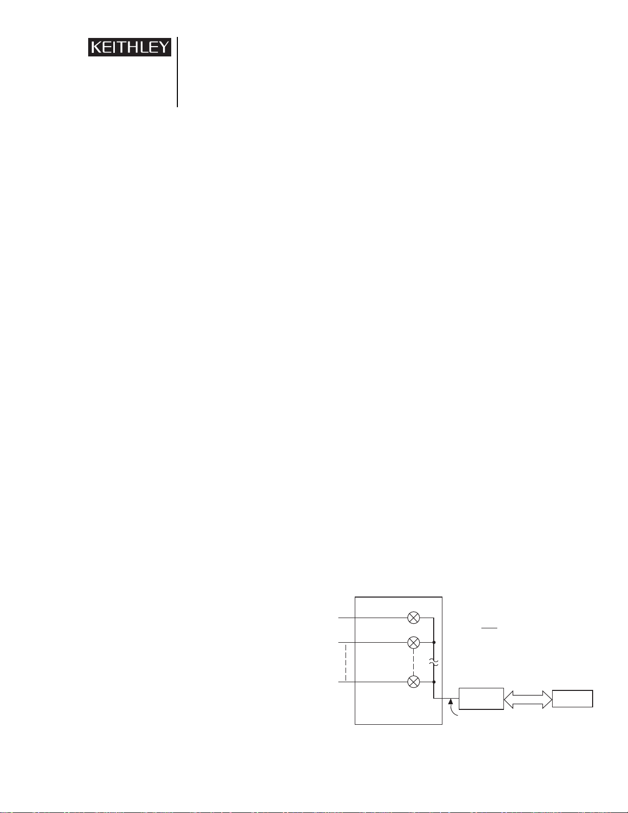
1. Direct without Compensation. The method shown in Figure
1 is simple and can provide adequate accuracy in monitoring
high temperatures (typically above 300°C). The computing
power of the controller is used to convert the voltage output
of the sensor to a temperature value, and to insert a constant
reference temperature into the conversion equation. This
assumed reference may be valid in well controlled operating
environments.
The major error is the difference between the constant
temperature assumed for the thermocouple reference and the
actual temperature at the terminal block (∆T
A
in Figure 1).
If the difference is no greater than ±6°C, the additional error
in monitoring temperatures above 300°C is less than 2%. An
error of this magnitude may be acceptable in many
applications.
Application Note
Series
Figure 1: Direct Multipoint Temperature Measurement without Compensation
7001/7002 Switch System
Switch
T
+ ∆T
S
2
A
2
T
1
T
2
T
N
7011 Switch Card
Assumed T
.
∆T
A
e
≤ × 100%
A
T
1
.
≤ 2% for T
e
A
T
= ±6°
T
A
Measurement
2001 DMM
Copper Wire
and ∆T
S
1
S
IEEE-488
A
Maximum
Additional
= 300°
= 30°
Error
Controller
Page 2
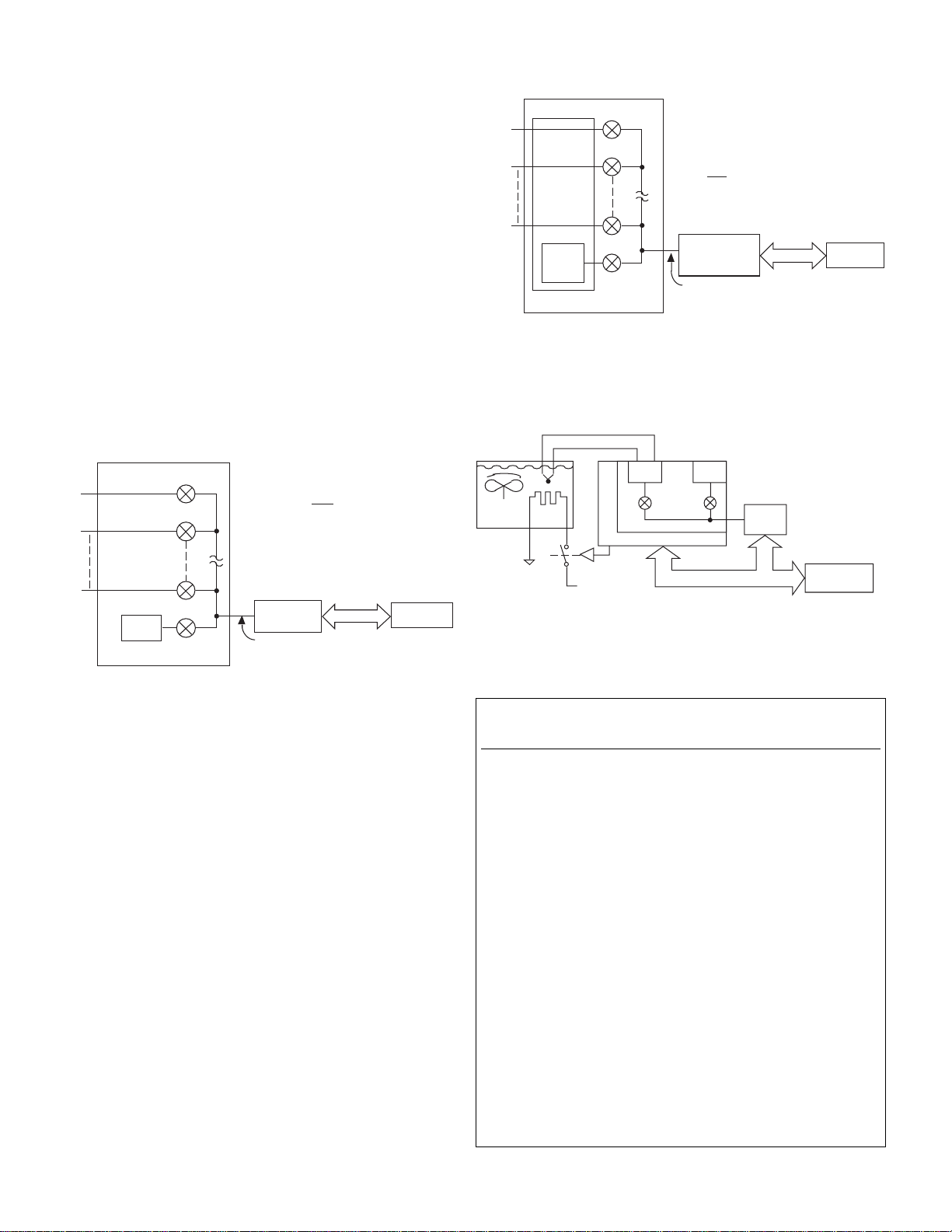
2. Compensation without Isothermal Block. When better accu-
racy is required, the temperature must be sensed at the thermocouple reference end. This can be accomplished by mounting a thermistor, RTD or semiconductor temperature sensor
near the termination. These reference sensors, unlike thermocouples, provide outputs that represents the temperature at the
point of interest, rather than the relative temperature difference between two points.
This method improves accuracy, since there is a temperature
detector near the thermocouple termination. The temperature
detector allows for fluctuation in the operating environment at
the reference end of the thermocouple. There is still a major
uncertainty, however, with respect to the temperature difference
between the temperature sensor and the thermocouple termination (∆TBin Figure 2). That temperature difference is uncon-
trolled and may vary substantially due to the location of convection and radiation heat sources, and also because of heat
conducted in electrical traces.
Note that with this method, the DMM must be switched to the
resistance mode to monitor the value of the reference sensor.
Also, the controller must be programmed with the characteristic equations to convert signals from both the thermocouple
sensor and the reference sensor.
3. Compensation with Isothermal Block. Using an isothermal
block (Figure 3) ensures that the temperatures at the thermocouple terminations differ by no more than a fraction of a
degree from the reference sensor temperature. This arrangement reduces the number and magnitude of system uncertainties and provides the best measurement accuracy.
In a typical application as presented in Figure 4, the
DMM reads the thermocouple and reference voltages; the
DMM then converts voltages to temperature values. The
Model 2001 DMM HI/LO limits can be set to control the
Digital I/O and therefore control the heater. This same system
may be extended to control or monitor up to 78 temperature
points. Those channels not dedicated to thermocouple sensors
can be used to monitor other signals and system test points.
Figure 5 illustrates a typical reference and thermocouple
measurement configuration.
Figure 2: Multipoint Temperature Measurement without Isothermal Block
Figure 3: Multipoint Temperature Measurement with Isothermal Block
Figure 4: Automatic Control of Oil Bath Temperature
Summary of Thermocouple System Uncertainties
System Uncertainty Design Considerations
1. Thermoelectric Offset • Select conducting materials with low
Voltages thermal characteristics. Clean copper wire
is very good.
• Match thermal characteristics of materials
brought together in any connection.
• Shield connections from all heat sources
(radiation, conduction, convection).
• Maintain gas-tight connections. Metal
oxides typically have much higher EMFs.
• Select quality low thermal switching.
2. Reference Temperature • Accuracy of the reference temperature
sensor is directly related to the degree of
system error.
• Isothermal block construction minimizes
errors created by differences between the
measured reference temperature and the
temperature at thermocouple terminations.
3. Measurement Instrument • Stability, sensitivity, and accuracy of the
instrument directly affect measurement
accuracy.
4. Thermal Curve Conformity • Thermocouples that have undergone ther-
mal shocks, mechanical stress, and aging
can exhibit errors approaching ±2°C from
standard tables and curves.
7001/7002 Switch System
T
1
T
2
- 1
T
N
T
Sensor
7011 Switch Card
2
2
2
2
S'
2Temp
.
TS = T
' ± T
S
.
∆T
e
≤ × 100%
B
T
1
.
e
≤ 0.7% for T1 = 300°
A
T
Measurement
2001 DMM
Copper Wire
Assumed ∆T
B
B
IEEE-488
Maximum
Additional
= ± 2°
B
Controller
B
Error
7001/7002 Switch System
T
1
T
2
Isothermal
Block
- 1
T
N
Temp
Ref
Device
7014 Thermocouple Switch
2
2
2
2
Isothermal Block Assures ∆T
Reference Accuracy Specified ≤ ± 0.25°C
Total Switch Uncertainty ≤ ± 0.30°C
0.30
= × 100% for T1 = 300°C
e
C
300
= 0.1% Max. Add'l Error
e
C
Measurement
2001 DMM
2182
Nanovoltmeter
Copper Wire
IEEE-488
≤ ± 0.05°C
C
Controller
Thermocouple
IEEE-488
= CH. 1
2001
DMM
I/O
Controller
Stir
Oil
Bath
T
J
Driver
CH. 2 REF
7014
7001 Scanner
Page 3
Resistance Measurements
Applications for resistance measurements in systems are numerous. They range from network and device testing to the testing of
backplanes and interconnects, as well as the use of platinum
resistance temperature detectors (PtRTDs) or thermistors.
Four-wire resistance measurements are used most often in
system applications to overcome errors introduced by cabling
and switch contact resistances. These effects are especially bothersome in the measurement of resistance values at 1kΩ and
below. One ohm of cable and contact resistance in a conventional 2-wire circuit adds a 0.1% error to the 1kΩ measurement.
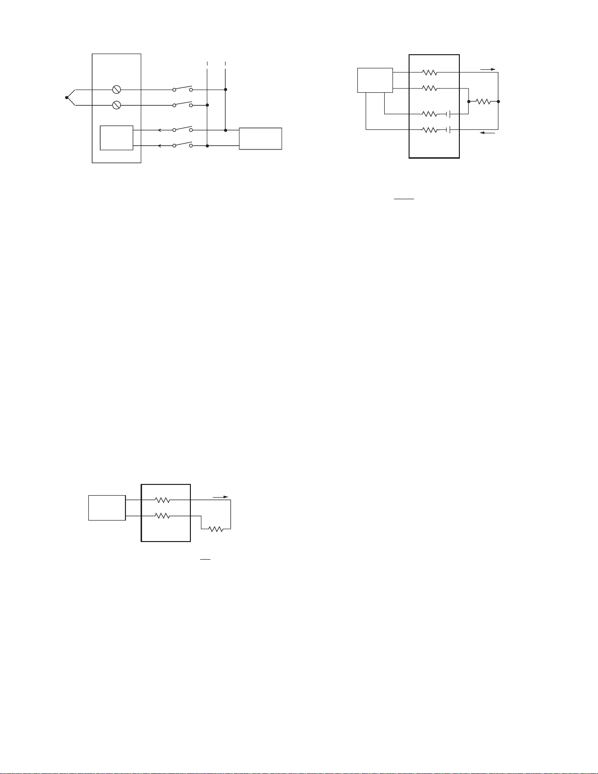
The effect of this cable and contact resistance (RC) is
shown in Figure 6. The DMM outputs a current, IX, which
develops a meter voltage, VM, proportional to the sum of the
unknown resistance and the series connection resistance RC. The
value of RCcould be measured separately by replacing RXwith a
short; RXis then determined by subtracting RCfrom the twowire measured value. While this may be practical for a manual
test, system testing uses a wide range of signal channels, relays,
and cabling. Each measurement path would require a separate
characterization of RC, an impossible and unnecessary task.
A four-wire resistance measurement, often called a Kelvin
measurement, is most common in system environments as a
means of avoiding series resistance errors. See Figure 7.
Ignoring for the moment the voltage (VTH) in Figure 7, a
current, IX, is still generated by the DMM from the Ω source terminals. Aseparate voltage sensing circuit uses the characteristic
high input impedance of the voltmeter. The sense current, I
S
, is
the input current of the voltmeter, and for all practical purposes
can be considered to be zero. Therefore, no voltage attributable
to ISis developed in the sense circuit, and voltage, VX, is proportional exclusively to the unknown resistance.
In precision measurements or very low resistance measure-
ments, there are additional considerations. For example, make a
measurement of a 1Ω resistance with 0.1% accuracy. Use a 51⁄2digit DMM on the lowest range (200Ω full scale) and a source
current, IX, of 10mA. The result would be:
VX= 10mV + V
TH
from the equation in Figure 7. Now assume that the thermoelectric offset voltage, VTH, is 30µ V. This condition results in an
additional measurement error of 0.3%. For low resistances, as in
thermistor temperature measurements, the system designer must
determine—in addition to the accuracy of the DMM—the
acceptable measurement uncertainty, and select appropriate
low voltage switching and interconnect circuitry. Applications
involving thermistors require low source current to minimize
self heating. The Model 2001 has high resolution and low source
current to minimize this source of error.
A good, low thermal design can achieve thermoelectric
offsets of only a few microvolts. These effects can be neutralized
by techniques such as measuring and subtracting the offset, or
using an alternating current for IX, to further improve on the
accuracy of low resistance measurements.
Model 2001 has a feature called “offset compensated
ohms” that reduces this effect. It takes two readings to give the
compensated reading, one reading with the test current applied
and one reading with no test current.
With no test current applied, the only voltage to be measured is the thermal EMFs in the circuit. With this measured, it
can be algebraically subtracted from the first reading. This provides an “offset compensated” measurement.
Isothermal
Figure 5: Typical Reference and Thermocouple Measurement Configuration
Figure 7: Four-Wire Resistance Measurement
Figure 6: Two-Wire Resistance Measurement
Block
T
A
T
J
T
B
Temp
REF
Device
T
R
V
TC
C
U
C
U
V
V
REF
M
2001 DMM
R
C
DMM V
VM = (R
C
M
Switch and
Interconnect
+ R
) I
% Error = × 100%
X
X
I
X
R
X
R
C
R
X
R
C
V
DMM
VX = ISRC + IXR
≈ I
V
X
% Error = × 100%
M
V
X
XRX
+ V
V
IXR
Switch and
Interconnect
+ V
X
TH
TH
X
R
C
V
TH
TH
I
X
R
X
I
≈ 0
S
Page 4
Low Current Measurements
Full characterization of semiconductor devices requires a broad
dynamic range (as many as 12 decades) of current stimuli and
measurement. Leakage currents of FET gates and reverse biased
junctions are well below 1nA. Insulation resistance of capacitors,
PC boards, cables, and harnesses can also be determined using
low current measurements. The measurement of these signals
requires some precautions, even in a manual setup. In a system,
the switching card becomes a critical element. It is advisable to
keep the following points in mind when selecting a switch to
make current measurements at levels below 1µ A:
1. The current switching configuration should be capable
of maintaining a complete path when the circuit is not being
measured.
2. There must be very high isolation (>10
13
Ω minimum)
between adjacent channels and between the relay drive and
the measurement channels. Such an arrangement minimizes
extraneous current paths, which may introduce error currents
into the measurement, especially noticeable below 1nA.
3. Provision for shielding is required, since the high
impedance circuitry is susceptible to pickup of spurious radiated noise. Relay controls should be shielded from the coil to
minimize induced noise from the relay drive power supply.
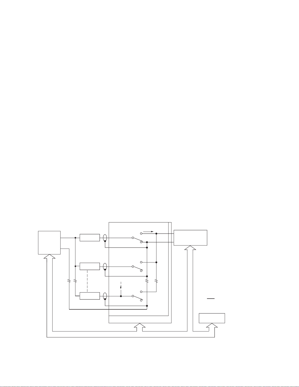
Presented in Figure 8 is a generalized leakage test system
in which a bias voltage, V
A
, is applied across each test device
and leakage currents are measured with an electrometer. The low
current switching card introduces less than 1pA of current into
the measurement circuit. The devices could be transistors,
diodes, or a multipin IC package where leakage currents into
certain nodes must be determined with other nodes in a known
state. DUT 1–10 may also represent a resistor network in which
isolation between circuits must be determined. Capacitor
leakages can be measured, as described in detail in Application
Note #120.
Construction techniques, materials, and cleanliness are
critical factors in the design of the low current interconnect. The
major contributors to error currents above 1pA are:
• Leakage currents. Effects can be reduced by selection of
proper insulating materials, guarding, and cleanliness.
• Triboelectric currents. This noise source can be reduced
by using special low-noise cable and securing the interconnect to minimize movement.
• Electrochemical current. Thorough cleaning of joints
and surfaces to remove electrolytic residue including PC
etchants, body salts, and processing chemicals will minimize the effect of these parasitic batteries.
Other current sources, including piezoelectric, dielectric,
photoelectric, and thermoelectric effects may also contribute to
error in low current measurements. Additional information on
these source problems and other related low current data are
provided in Keithley’s Catalog and Reference Guide and Low
Level Measurements Handbook. The critical sources of current
error are dependent on the levels and types of measurement
being performed.
Figure 8: Automated Leakage or High Resistance Testing. The Model 6517A has an isolated voltage source that can be used to stimulate the device under
test. The Model 6517A can then measure the developed current.
Low Current Switch
I
M
6517A
Voltage
Source
+
V
A
-
DUT 1
DUT 2
IL < 1pA
DUT 10
6517A
Electrometer
Application:
I
GSS
on PN Junctions
I
R
on Capacitors
I
L
R = High MEG Resistors
on FETs
V
A
I
M
7158 Low Current Switch
7001 Switch System
Controller
IEEE-488
Page 5
High Voltage Switching
Many procedures and parametric tests (such as insulation resistance testing on cables, harnesses, and PC boards, high-pot testing, and breakdown testing on semiconductors) require voltages
from 500V to 1000V. Often these requirements are specified as
part of a standardized test method such as MIL-STD-833C.
Since transients can be generated in the switching of high
voltages, it is also generally required that the application of voltage be increased at a specified maximum rate. Because programmable high voltage supplies are not readily available, manual
methods are often used to apply the test voltage in a controlled
manner. Manual methods generally consist of adjusting a potentiometer or front panel control on the supply, a very loosely controlled situation. These methods are time consuming and can be
hazardous to the operator unless safety interlocks are carefully
designed.
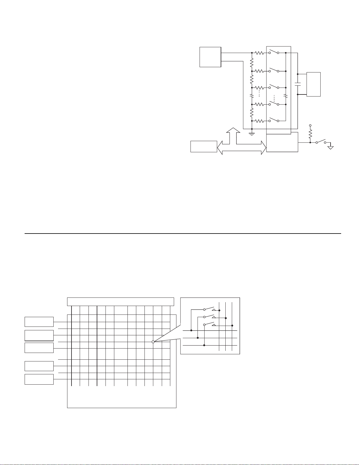
An alternative is to approximate linear application of voltage, using a Model 7054 High Voltage Scanner Card and a constant voltage supply. The circuit illustrated in Figure 9 charges
capacitor C to voltages from taps on the divider networks. The
charge rate is predictable and controlled. Maximum dV/dt at the
DUT can be controlled through design selection of R and C, and
system timing of the relay closures. Steps may be of any size,
depending on the number of taps on the divider network.
The controller can read the status of safety interlocks
through the digital I/O port on the Model 7001 Switch System to
assure safe testing. Values for R
1
through R9are selected to
approximately equalize the RC response between taps. R
B
is a
bleeder resistor selected to bleed charge safely from capacitor C
at the completion of testing.
Matrix Switching
The matrix switch is commonly used in large systems. Its ability
to connect any input to any output through only one set of contacts assures maximum flexibility in configuring system measurements. Using a matrix, connections and circuits can be completed at the test interface or within the matrix. System checks
and validation can be performed in the matrix without external
hardware. For example, the DMM in Figure 10 can be used to
monitor voltages at any test interface point in columns 1 through
12. The voltages’ source can be measured by connecting it with
the DMM via the same column inside the matrix. Amatrix combines a complex set of switching applications into one array. The
Model 707A is a matrix mainframe that has switching cards that
are 8×12 matrices. These cards can be
cascaded to increase the number of
rows and columns for an even more
powerful array of switching capability.
Caution is advised in regard to
matrix switching. Benefits gained
through switching flexibility can be
offset by catastrophic situations if care
is not taken to verify all signal pathways. Closure of incorrect matrix
crosspoints may produce internal
shorts that can damage the relays,
DUT, or system’s instrumentation.
It is therefore imperative that the test
designer know and verify each crosspoint configuration during test development before proceeding with
“power up” testing.
Figure 9: Uniform High Voltage Application for Breakdown and Isolation
Testing
Figure 10: Uniform High Voltage Application for Breakdown and Isolation Testing
7054
High Voltage
Card
R
248
High
Voltage
Source
Controller
+
VA = 1000V
-R
R ≈ 1.1MΩ
To other
Instrumentation
IEEE-488
1
CH. 1
R
2
R
R
CH. 2
R
3
CH. 3
R
9
CH. 9
R
B
CH. 10
7001
Switch
System
C
I/O
DUT
+5V
Safety
Interlock
Device Under Test
Column
1 23456 78
Row
2001 DMM
6517A
Electrometer
220 I-Source
230 V-Source
Function
Generator
A
B
C
D
E
F
G
H
I
7071 Matrix Card in Model
707A Switching Mainframe
9 10 11 12
Crosspoint
Schematic
HI
LO
Guard
Page 6
Keithley Instruments, Inc. • 28775 Aurora Road • Cleveland, Ohio 44139 • 440-248-0400 • Fax: 440-248-6168 • www.keithley.com
BELGIUM: Keithley Instruments B.V. Bergensesteenweg 709 • B-1600 Sint-Pieters-Leeuw • 02/363 00 40 • Fax: 02/363 00 64
CHINA: Keithley Instruments China Yuan Chen Xin Building, Room 705 • 12 Yumin Road, Dewai, Madian • Beijing 100029 • 8610-62022886 • Fax: 8610-62022892
FRANCE: Keithley Instruments Sarl B.P. 60 • 3, allée des Garays • 91122 Palaiseau Cédex • 01 64 53 20 20 • Fax: 01 60 11 77 26
GERMANY: Keithley Instruments GmbH Landsberger Strasse 65 • D-82110 Germering • 089/84 93 07-40 • Fax: 089/84 93 07-34
GREAT BRITAIN: Keithley Instruments Ltd The Minster • 58 Portman Road • Reading, Berkshire RG30 1EA • 0118-9 57 56 66 • Fax: 0118-9 59 64 69
INDIA: Keithley Instruments GmbH Flat 2B, WILOCRISSA • 14, Rest House Crescent • Bangalore 560 001 • 91-80-509-1320/21 • Fax: 91-80-509-1322
ITALY: Keithley Instruments s.r.l. Viale S. Gimignano, 38 • 20146 Milano • 02/48 30 30 08 • Fax: 02/48 30 22 74
NETHERLANDS: Keithley Instruments B.V. Postbus 559 • 4200 AN Gorinchem • 0183-635333 • Fax: 0183-630821
SWITZERLAND: Keithley Instruments SA Kriesbachstrasse 4 • CH-8600 Dübendorf, Zurich • 01-821 94 44 • Fax: 01-820 30 81
TAIWAN: Keithley Instruments Taiwan 1 Fl. 85 Po Ai Street • Hsinchu, Taiwan, R.O.C. • 886-3572-9077• Fax: 886-3572-9031
© Copyright 1999 Keithley Instruments, Inc. No. 1138
Printed in the U.S.A. 59910KAP
Specifications are subject to change without notice.
All Keithley trademarks and trade names are the property of
Keithley Instruments, Inc. All other trademarks and trade
names are the property of their respective companies.
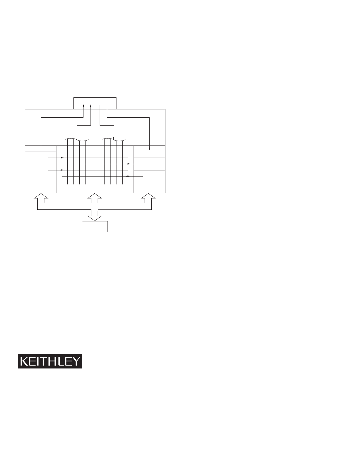
The general case for system switching is illustrated in
Figure 11. As implied by its position in the diagram, switching
is central to good system design.
Careful consideration of switch characteristics is essential
to optimize performance of the measurement system. Once the
switch is selected, the application of basic measurement principles will assure reliable and accurate measurement of circuit
parameters.
Conclusion
When designing a measurement system, selection of the switch
is as critical as the selection of system instrumentation or the
design of the test interface. The intended application must be
thoroughly considered and the switch selected must meet the
requirements of the application. Careful attention to detail and to
the basic principles of measurement can assure system accuracy
and performance.
Figure 11: Application of Matrix Capability in a General Purpose Test System
Device Under Test
Test Interface
1
2
3
Stimuli Switching Measurement
IEEE-488
Controller
4
5
6
 Loading...