

Page 1

Model 4288-4 Dual Fixed Rack Mounting Kit
Introduction
This packing list contains the parts list and installation information for the Model 4288-4 Dual Fixed Rack Mounting Kit. The
Model 4288-4 includes all of the hardware necessary for side-by-side rack mounting of a 3½-inch high instrument (Models
182, 428, 486, 487, 776, 2000, 2001, 2002, 2010, 2304, 2400, 2410, 2420, 7001) and a 5-inch high instrument (Models 195A,
196, 220, 224, 230, 263, 595, 614, 617, 705, 740, 775, etc.). The rack mounting kit can be installed in a standard 19-inch rack.
Parts list
Table 1 lists the parts supplied with a Model 4288-4 Dual Fixed Rack Mounting Kit.
Table 1. Model 4288-4 dual fixed rack mounting kit parts list
Keithley
Qty. Description
1
Chassis
2
Bracket, rear support
1
Front panel
1
Clamp (for 3½-inch instrument)
1
Clamp assembly (for 5-inch instrument)
1
Clamp (for 776 only)
1
Spacer(for all 3½-inch products other than 2000, 2010, 2400,
and 776)
part no.
4288-4-301
BR-21
4288-4-303
4288-4-302
1019A-303
4288-4-305
4288-4-304
Rear support brackets to chassis:
4
10-32 Kepnut
4
10-32 x ⅜ Phillips pan head screw
Rear support brackets and front panel to rails:
8
Fastener captive nut
8
10-32 x ⅝ Phillips pan head screw
Clamps to chassis:
6 8-32 x ⅜ Phillips pan head screw 8-32x⅜PPH
Spacer to chassis:
2 Plastic fastener FA-240
10-32KEPNUT
10-32x⅜PPH
FA-148
10-32x⅝PPH
PA-385 Rev. C / 2-00
Page 2
Rack preparation
1. Select a location in the rack. The assembly will take up 5¼ inches of vertical space.
2. Hold up the front panel at the selected location in the rack. The four slotted mounting holes in the front panel dictate the
location of the captive nut fasteners on the four rack rails. Mark where the fasteners are to be installed.
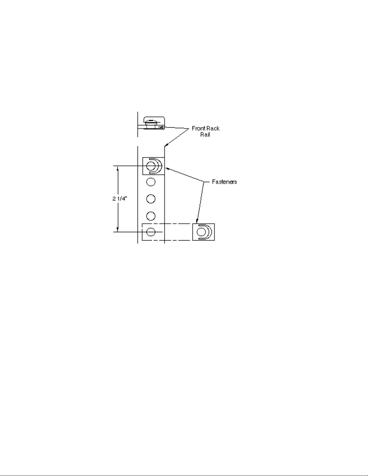
3. Referring to Figure 1, install four fasteners so that the captive nuts are located behind the appropriate holes on the front
rack rails.
Figure 1
Fastener installation
Instrument preparation
1. Remove the handle from the 3½-inch instrument. There are two styles of handles; the newer style has orientation arrows
at each handle end that are molded onto the plastic.
A. With the old style handle, rotate it to the uppermost position. With the new style, rotate it under the instrument until the
arrows on the handle ends line up with arrows on the mounting ears.
B. Pull out on the handle ends until the handle is clear of the mounting ears, and then remove the handle.
2. Remove the screw that secures each mounting ear to the case, and remove both mounting ears.
NOTE
Save all removed parts for reinstallation if the instrument is ever removed from the rack in the future.
Page 3

Mounting kit installation
Refer to Figure 2 to install the chassis, support brackets, and front panel in the rack and attach the instruments to the chassis.
Figure 2
Mounting kit installation
1. Loosely attach the rear support brackets to the chassis with Kepnuts and the 10-32 x ⅜ screws.
2. Position the chassis assembly in the rack to adjust the rear support brackets and note the location for the captive nut fasteners on the rear rack rails.
3. Install four fasteners so that the captive nuts are located behind the appropriate holes on the rear rack rails.
4. Loosely attach the chassis assembly to the front and rear rack rails with 10-32 x ⅝ screws. Secure the rear support brackets
to the chassis.
5. Loosely attach the front panel to the rack rails.
6. Install spacer (see Figure 3).
7. Slide the instruments onto the chassis shelf from the rear of the rack. The feet of the 3½-inch instrument will fit into holes
in the shelf. The front panel will stop the 5-inch instrument. See the Model 776 installation if applicable.
8. Attach the clamps to the chassis shelf with 8-32 x ⅜ screws. (The clamps should extend over the lip on the rear panel of
the instruments.) Note that there are two sets of mounting holes for clamping 3½-inch high instruments of different lengths.
9. Tighten all screws.
Page 4

Model 776 installation
1. Remove the two lower rear panel screws from the Model 776.
2. Slide the instrument onto the chassis shelf from the rear of the rack. The feet of the Model 776 will fit into holes in the shelf.
3. Position the clamp, as shown, against the rear panel.
4. Reinstall the two rear panel screws through the clamp (4288-4-305).
5. Attach the clamp to the chassis with 8-32 x ⅜ screws.
6. Tighten all screws.
Installation of spacer
Once the spacer is installed, continue with the installation instructions for 3½ inch instruments.
Figure 3
Spacer installation
 Loading...