

Page 1

Keithley Instruments, Inc.
28775 Aurora Road
Cleveland, Ohio 44139
1-888-KEITHLEY
www.keithley.com
Capacitance Voltage Unit (CVU) Quick Start Guide
Model 4200-CVU
Model 4200-CVU Quick Start Guide overview
You can quickly begin using your Keithley Instruments Model 4200 Capacitance Voltage Unit (Model 4200-CVU) by
performing the steps in this Quick Start Guide (QSG). For detailed information about the Model 4200-CVU, refer to
the Complete Reference CD-ROM that came with your Model 4200-SCS Semiconductor Characterization System.
The steps outlined below and detailed in the following pages will allow you to quickly begin using your
Model 4200-CVU:
• Step 1: Unpack your Model 4200-SCS.
• Step 2: Make basic system connections (power cord, keyboard, and optional printer)
• Step 3: Connect a test fixture to the Model 4200-SCS (Model 4200-CVU card preinstalled)
• Step 4: Power-up and log on
• Step 5: Start the KITE software and select the “cv-cap” test in the default project
• Step 6: Define your test
• Step 7: Run the “cv-cap” test
• Step 8: View the data sheet
• Step 9: View the graph
• Step 10: Print and export data
The example in this QSG uses the default project and runs the “cv-cap” test. If you wish to select a different project
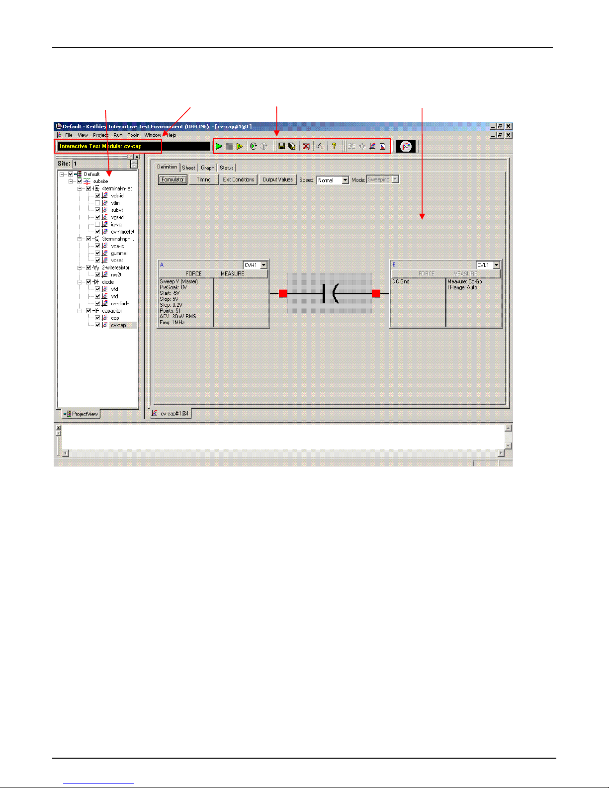
and/or test, you must modify the procedures accordingly. Figure 1 shows how the Keithley Interactive Test
Environment (KITE) window will look after the default project and “cv cap” test are selected.
PA-952 Rev. A / November 2007 1
Page 2
Model 4200-CVU Quick Start Guide
Figure 1: KITE interface with the "cv-cap" test selected in the default project
KITE Workspace Toolbar Selected Test Project Navigator
2 PA-952 Rev. A / November 2007
Page 3
Model 4200-CVU Quick Start Guide
Quick-start instructions
Step 1: Unpack your Model 4200-SCS
The box contains:
Model 4200-SCS Semiconductor Characterization System, with the Model 4200-CVU card int egrated into
the mainframe.
NOTE: How to lift the Model 4200-SCS:
• Lift from the bottom, not from the front bezel.
• Set it on a bench or install it in a rack using the optional slide rack mounting kit.
Keyboard with built-in pointing device
Two triax cables for each source-measure unit (SMU)
Four red SMA to SMA cables for the Model 4200-CVU
Connectors: Four SMA to BNC adapters; 2 BNC tees
Y-Cable: Use to connect the keyboard to the mainframe
Power cord
Model 4200-SCS KTE Interactive CD-ROM
Model 4200-SCS Complete Reference CD-ROM
Step 2: Make basic system connections (power cord, keyboard, and optional
printer)
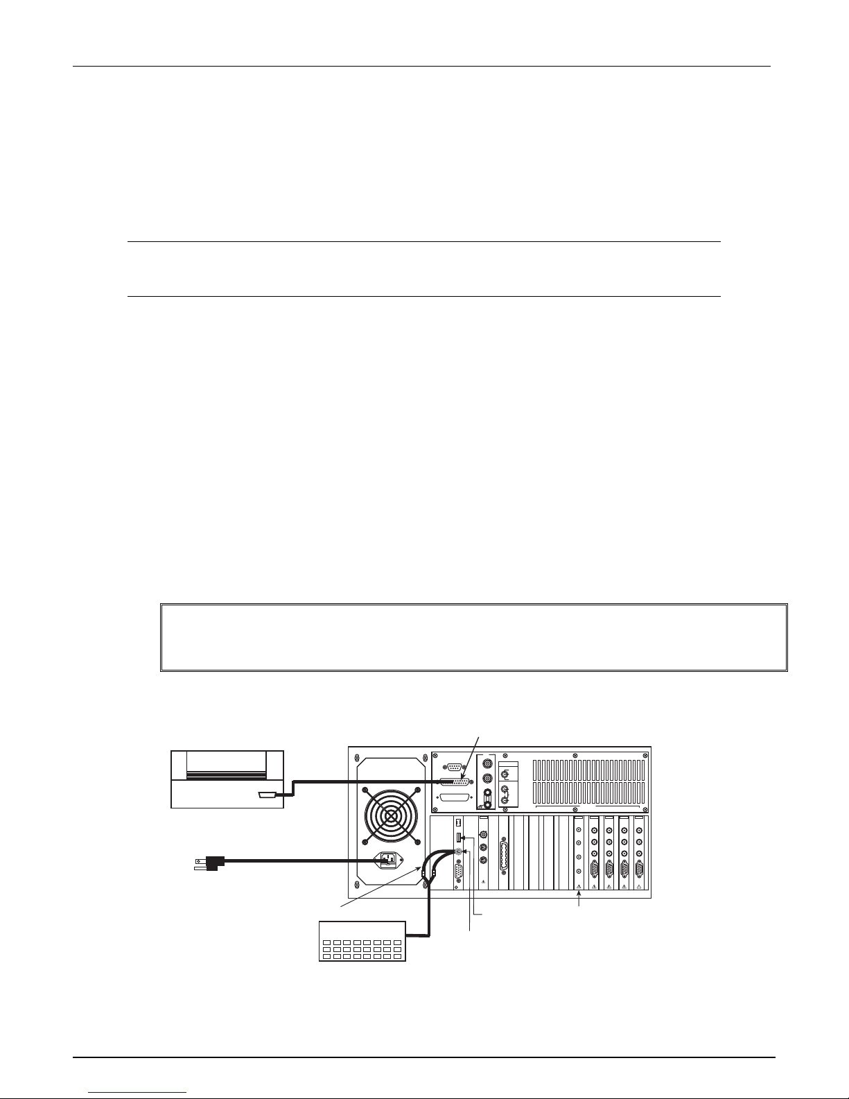
Basic system connections to the Model 4200-SCS (shown in Figure 2) include the keyboard (which has a builtin pointing device), the supplied power cord, and an optional printer. If you are using a USB printer, connect it
to the USB port.
WARNING Plug the female end of the supplied power cord into the Model 4200-SCS, but
DO NOT connect the male end to line power at this time. Steps 2 and 3 in the
QSG must be performed with the line power disconnected.
Figure 2: System connections
Parallel
Printer
Power Cord
(supplied)
Shielded
Parallel
Cable
Y-Cable (supplied)
Keyboard
Parallel
Connector
GNDU
S
COM 1
E
N
S
E
F
O
LPT 1
R
C
E
SMU AND GNDU
C
O
M
M
GUARD
O
N
INSTALLATION
CATEGORY
I
KEITHLEY
4200
TM
INTLK
IN
OUT
USB
Port*
Mouse/Keyboard
Connector
INSTRUMENT
CONNECTIONS
SMU ONLY
SENSE LO
GUARD
SENSE LO
COMMON
SENSE
COMMON
FORCE
SLOT8SLOT7SLOT6SLOT5SLOT4SLOT3SLOT2SLOT
4200-CVU
* v1.1 USB connector (Windows
XP Professional operating
system) – If using a USB printer,
connect it to the USB port.
INSTRUMENTS
KEITHLEY
4200
CVU
HCUR
HPOT
LPOT
LCUR
Card
Keithley
4200-SCS
KEITHLEY
KEITHLEY
KEITHLEY
4210
4210
SMU
SMU
SENSE LO
SENSE LO
SENSE LO
SENSE
SENSE
FORCE
FORCE
PA CNTRL
PA CNTRL
PA CNTRL
1
KEITHLEY
4200
4200
SMU
SMU
SENSE LO
SENSE
SENSE
FORCE
FORCE
PA CNTRL
PA-952 Rev. A / November 2007 3
Page 4
Model 4200-CVU Quick Start Guide
Step 3: Connect a test fixture to the Model 4200-SCS (Model 4200-CVU card
preinstalled)
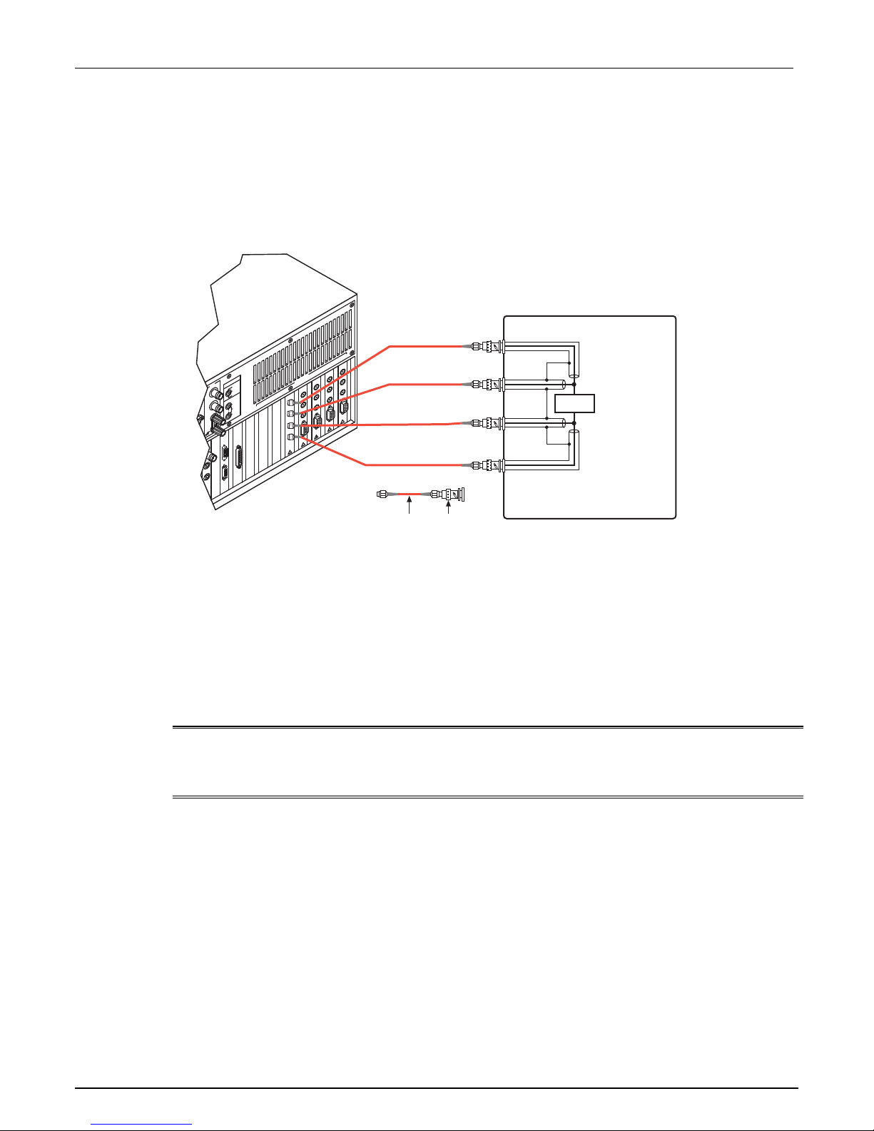
Figure 3 shows how to connect a BNC test fixture to the Model 4200-SCS. The red SMA cables and BNC
adapters are supplied with the Model 4200-CVU card.
Figure 3: DUT test fixture connections to the Model 4200-CVU
Use supplied torque
wrench to tighten
SMA connections
to 8 inch-lbs.
T
O
L
S
1
T
LO
S
2
SE LO
T
SEN
O
L
S
3
SE LO
S
T
SE
N
T
SEN
E
O
SEN
M
L
S
N
S
E
N
M
U
IO
R
T
T
C
S
O
Y
E
L
U
L
N
IN
N
D
E
N
S
D
N
O
N
O
R
G
E
A
U
C
T
S
U
M
O
G
S
L
E
S
N
E
S
N
O
M
M
S
O
U
C
D
E
N
N
G
D
S
N
A
E
U
E
S
M
N
S
E
S
N
O
M
F
M
O
O
L
C
O
R
C
E
C
O
M
M
O
N
N
I
T
U
O
S
8
D
R
E
A
C
U
R
G
O
F
U
R
4
T
S
LO
IN
ENSE
T
S
ENSE
O
S
L
S
5
E
T
S
O
SL
6
T
O
L
S
S
7
R
T
U
C
H
F
T
O
P
H
T
O
P
L
R
A
U
P
C
L
CE
R
O
O
L
F
E
S
N
ENSE
S
RCE
O
F
E
S
N
E
E
C
R
FO
E
C
R
O
N
C
L
A CNTR
P
TRL
CN
PA
L
NTR
A C
P
L
R
T
A
HPOT
LPOT
LCUR
B
A = SMA Cable (male to male) (supplied)
B = SMA (female) to BNC (male) Adapter (supplied)
HCUR
Metal Test Fixture
DUT
Use coax cables to extend SMA
shielding to the DUT, and then
connect them together.
Step 4: Power-up and log on
1. Make sure the POWER switch is in the OFF (out) position. The POWER switch is located on the front panel
in the lower right corner.
2. Plug the male end of the line cord into a properly-grounded AC line power receptacle.
3. Turn on the Model 4200-SCS by pushing in the POWER switch to the ON (in) positio n.
4. At the KIUSER prompt, press ENTER. There is no password for this account.
CAUTION When first starting a KTE Interactive software tool, you must answer "Yes" to an
on-screen license agreement. Answering "No" makes your system nonfunctional
until you reinstall the software.
4 PA-952 Rev. A / November 2007
Page 5

Model 4200-CVU Quick Start Guide
Step 5: Start the KITE software and select the “cv-cap” test in the default
project
1. Start the KITE software by double-clicking the KITE icon on the Microsoft® Windows® desktop (see Figure 4):
Figure 4: The KITE icon
Double-click to start KITE
2. When KITE starts, the default project will open automatically. If a different project opens, perform the three
steps in Figure 5 to open the default project. The Project Navigator for the default project is shown in
Figure 1.
NOTE If the Project Navigator is not displayed when KITE is started, click the View menu
and select the Project Navigator item. The View menu is located on the upper left side
of the menu bar in the KITE window.
Figure 5: Open default project
1 From the File menu,
click Open Project
NOTE When browsing, use the following directory path to locate the “default.kpr” project file:
C:\S4200\kiuser\Projects\default\default.kpr
3. Select the “cv-cap” test, as shown in Figure 6.
PA-952 Rev. A / November 2007 5
2 Use the browser to select
the default project
3 Click Open to open
the default project
Page 6

Model 4200-CVU Quick Start Guide
Figure 6: Default project in Project Navigator: Selecting the “cv-cap” test
Double-click “cv-cap” to select the
test
The checkbox for “cv-cap” must be
checked in order to run the test. If
unchecked, click the checkbox to
insert a 9
Step 6: Define your test
The test is defined from the test Definition tab shown in Figure 7. As shown in the tab, the device in this example is
connected to the CVH1 and the CVL1 terminals of the Model 4200-CVU. In this test, the DC bias is swept from -5V
to 5V in 0.2V steps, with a 1MHz capacitance measurement taken at each step.
1. If desired, the setup for cv-cap can be changed. A settings window is displayed by clicking the appropriate
FORCE MEASURE bar as shown in Figure 7. Figure 8 shows the Forcing Functions / Measure Options
window for cv-cap setup.
6 PA-952 Rev. A / November 2007
Page 7

Model 4200-CVU Quick Start Guide
Figure 7: cv-cap Definition tab: How to display a setup window for the CVU instrument
A. Select Definition tab
Figure 8: Setup for CVU pin CVH1
B. Click to set up the CVH1 terminal
settings
These parameters
set up the DC bias
sweep
This pull-down menu
selects the format of
the measured data
(e.g., the Measure
Model)
Key AC
settings
PA-952 Rev. A / November 2007 7
Page 8

Model 4200-CVU Quick Start Guide
2. After making any changes to the test definition, click the Save All button on the toolbar to save the settings
(see Figure 9).
Figure 9: The Save All button
Click Save All to
save settings.
Step 7: Run the “cv-cap” test
1. In the Project Navigator (see Figure 6), make sure the “cv-cap” test is highlighted and the checkbox is
checked.
2. On the toolbar, click the green Run Test button to run the test one time (see Figure 10).
Figure 10: The Run Test button
Click Run Test
to start test.
While the test is running, the Run Test button turns gray and the Abort Test button turns red. Also, the
MEASURING indicator (located on lower right corner of the front panel) will be on while the test is running. When
the test is finished, the Run Test button turns green.
Troubleshooting hints:
• A selected test will not run if the Run Test button is not green. Here are a few reasons why the Run Test
button will not be green:
- A test is still running.
- The checkbox for the test is not checked (see Figure 6).
- Changes to the test setup were not saved (see Step 6B).
• If a selected test still will not run, click the Status tab for the test. This tab provides status information for
the test.
Step 8: View the data sheet
The data sheet for the “cv-cap” test is displayed by clicking the Sheet tab for the test. Use the tabs at the bottom of
the Sheet to display the data type. A sample data sheet for the “cv-cap” test is shown in Figure 11.
8 PA-952 Rev. A / November 2007
Page 9

Model 4200-CVU Quick Start Guide
Figure 11: Sample data sheet for the “cv-cap” test
Click to export
data (see Step
10)
Click to display
Data Sheet
Click to display
Calc Sheet
Click to display
Settings Sheet
NOTE To select more than one sheet for selective printing, hold down the Ctrl key and then
click the tab. See Step 10 to print Sheet data.
Step 9: View the graph
The graph for the “cv-cap” test is displayed by clicking the Graph tab for the test. A sample graph for the “cv-cap”
test is shown in Figure 12. Notice that the extracted NOISE parameter is included on the screen.
The Graph Settings menu (shown in Figure 13) was used to select the Legend box and change series colors.
PA-952 Rev. A / November 2007 9
Page 10

Model 4200-CVU Quick Start Guide
Figure 12: Sample graph for “vds-id” test
10 PA-952 Rev. A / November 2007
Page 11

Model 4200-CVU Quick Start Guide
Figure 13: Graph Settings menu
To display the Graph Settings menu: Right-click
your mouse anywhere in the graph area.
OR
From the Tools menu, select Graph...Settings.
Use the Data
Variables properties
dialog box to display
extracted parameters
– NOISE in this case
Auto Y-axis
By default, the Y-axis does not automatically scale. To automatically achieve optimum resolution for the Y-axis,
select auto scale as follows:
1. Right-click anywhere on the graph to display the graph settings menu shown in Figure 13.
2. In the menu, click Auto Properties to display the Axis Properties window.
3. Click the Y1 Axis tab, and then click Auto Scale to insert a check mark in the box for Auto.
4. Click OK to close the window and enable auto scale for the Y-axis.
PA-952 Rev. A / November 2007 11
Page 12

Model 4200-CVU Quick Start Guide
Step 10: Print and export data
Printing Sheet data
1. In the KITE workspace, click the Sheet tab to display test data. You can selectively print the Data sheet,
Calc sheet, and/or the Settings sheet. Figure 11 and the NOTE that follows it show how to select sheets for
printing.
2. From the FILE menu (at the upper left side of the KITE window), select the Print option.
3. In the Print setup window, there are two print options. You can print the Selected Sheet(s) (Data, Calc,
and/or Sheet) or the Entire Workbook (Data, Calc, and Sheet).
4. In the Print setup window, click OK to print the data.
Printing the graph
1. In the KITE workspace, click the Graph tab to display the graph.
2. From the FILE menu (at the upper left side of the KITE window), select the Print option.
3. In the Print setup window, click OK to print the graph.
Exporting data into a Microsoft
1. In the KITE workspace, click the Sheet tab to display the test data.
2. In the Sheet tab, click the Save As button as shown in Figure 11.
®
Excel-compatible worksheet
3. From the Save As setup window, specify a file name and path and click Save. The default directory path
for exporting data is C:\S4200\kiuser\export.
Additional projects for the Model 4200-CVU
The following additional projects have been created for the Model 4200-CVU are located in the “_CV” folder in the
Projects directory:
CVU_BJT CVU_Capacitor CVU_InterconnectCap
CVU_ivcvswitch CVU_lifetime CVU_MobileIon
CVU_MOScap CVU_MOSFET CVU_nanowire
CVU_PNjunction CVU_PVcell
Perform the following steps to open one of the above project plans:
1. Click File at the top of the Keithley Interactive Test Environment (KITE) window and select Open Project
from the drop-down menu.
2. In the Open KITE Project File window, navigate back (up one level) to the Projects folder.
3. Double-click the _CV folder.
4. Open the desired CVU project.
12 PA-952 Rev. A / November 2007
 Loading...