

Page 1

Instruction Manual
Model 415
Micro-Microammeter
Keithley Instruments, Inc.
Instrument Division
Cleveland, Ohio, U.S.A.
Page 2
WARRANTY
We warrant each of our products to be free
from defects in material and workmanship. Our
obligation under this warranty is to repair or
replace any instrument or part thereof (except
tubes and batteries) which, within a year after
shipment, proves defective upon examination.
To exercise this warranty, contact your Keithley
field engineering representative. You will be
given assistance and shipping instructions.
REPAIRS AND RECALIBRATION
Keithley Instruments and its internat.ional dis-
tributors maintain complete repair facilities.
To insure prompt repair or recalibration service,
please contact your Keithley field representative
before returning the instrument.
Estimates for repairs, normal recalibrations, and
calibrations traceable to the National Bureau of
Standards are available upon request.
Page 3
INSTRUCTION MANUAL
MODEL 415
MICRO-MICROAMMETER
Page 4
CONTENTS
SECTION
INTRODUCTION
SPWZIFICATIONS
REXlgeS
Accuracy
Zero Drift
Grid Current
output
Rise
Time
Current Suppress~ion
Zero Check
Tube Complement
Power
Accessories Supplied
Accessories Available
Dimensions
OPERATION
Operating Controls
Inout and Outpyt Connections
PrelimJ.nary Set Up
Makinp Measurements
Speed o.f Response
I
II
CIRCUIT DESCRIPTION
Circuit Block Diagram
Speed of Response
Detailed Circuj.t Description
MAINTENANCE AND CALIBRATION
General
Calibration
Trouble Shooting Procedure
Voltare Resistance Diagram
Circuit Schematic
Replaceable Parts List
415
ICE= mm, nio.
IV
v
cLEvEm, OHIO
Page 5
SkCTION I - INTRODUCTION
The Model h15 Micro-microammeter incorporates advanced
high-speed circuitry developed by Keithley Instruments for rocket
and satellite experimentation -- where measurements of LymanAlpha night slow, cosmic radiation, and upper air density require fast response,
The I~15 also provides zero suppression up to 100 full scales,
permitting full scale display of one per rant variatiors of a
signal, or suppression of a steady background signal.
Excelling other Keithley LOO Series Micro-microammeters in
speed of response, the Model hl5 is ideal for current measure-
ments in ion chambers, ionization pages, and photo-multipliers.
Other applications include uses with flame and Beta-ray
ionization detectors and in gas ChromatoKranhy, mass spectrometry.
Speed of respp? se of less than 600 milliseconds to 90% of
final value at lo-
capacity is less than 50 picofarads (uuf). Critical damping of
the circuit, with any input capacity, is maintained on all ranges
through one infrequent adjustment. There is no possibili.ty of
oscillation or poor transient response on any ranpe.
ampere is possible where external circui~t
-8
Accuracy is 22% of full scale o 10m3
ranses; -+3$ of full scale on 3 x 10
ranples.
Other features i
approximately 1 x 10
2% per day and a one volt output at one milliampere; a 1%
mirror scale pane:1 meter.
lude capability of detecting current of
-YE
ampere; zero stability of better than
-9
throuph 10
througQ210
ampere
ampere
415
-1
I
Page 6
SECTION II -
SPECIFICATIONS
RANGES: lo-=, 3 x 10-12, lo-, 3 x lo-=,
etc. to 10e3 ampere
full scale.
ACCURACY: Z 2% of full scale 10e3 ttiu lOWE ampere ranges;+ 3% of
full scale 3 x 10⁻⁹ thru lo-l2 ampere ranges.
Z!SO DRIFT: After 30-minute warmup, less than 2% of full scale per
2L hours on all ranges.
GRID CT:r'WNT: Less than 5 x 10-lL ampere.
~!ITPIIT:
One volt for ful! scalp
3~i.
up to 5 ma. Noise less than
20 m'llivolts.
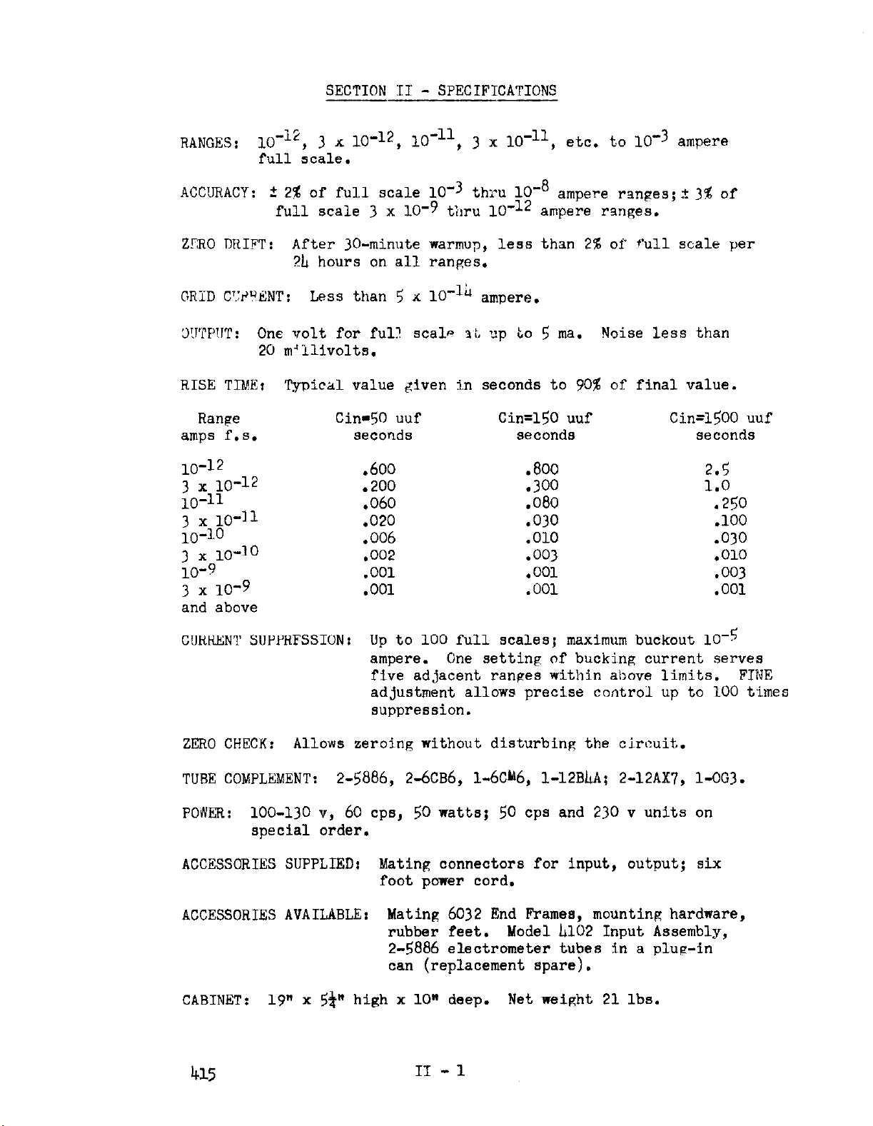
RISE TIME: Typical value &ven in seconds to 90% of final value.
Range Gin-50 uuf
amps f.s.
10-12
3 x 10-12
10-11
3&o-ll
seconds
.600
.200 .300 1.0
,060
.020
Cin=150 uuf
seconds
.800 2.5
.080 .250
,030 .lOO
Cin=1500 uuf
seconds
.006 ,010 .030
3 x 10⁻¹⁰
10-9
3 x 10'9
,002
.OOl
.OOl
.003 .OlO
.OOl .003
.OOl .OOl
and above
CURRENT SUPPRFSSION:
Up to 100 full scales; maximum buckout 10-5
ampere.
One setting of bucking current serves
five adjacent ranges within above limits. FINE
adjustment allows precise control up to 100 times
suppression.
ZERO CHECK:
TUBE COMPLEMENT:
POAER:
Allows zeroing without disturbing the circuit.
2-5886, 2-6CB6, l-6Ch6, l-12BLA; 2-12AX7, l-OG3.
loo-130 v, 60 cps, 50 watts; 50 cps and 230 v units on
special order.
ACCESSORIES SUPPLIED1 Mating connectors for input, output; six
foot power cord.
ACCESSORIES AVAILABLE:
Mating 6032 End Frames, mounting hardware,
rubber feet. Model L102 Input Assembly,
2-5886 electrometer tubes in a plug-in
can (replacement spare).
CABINET:
19" x 59 high x 10" deep. Net wei&ht 21 lbs.
415
II - 1
Page 7
SECTION III - OPERATION
A. OPERATING CONTROLS
-
The controls are discussed in order from left to right on the
front panel.
ZERO CHECK: Depressins this control effectively re-
(1)
moves all current from the amplifier input and allows
the meter to be set to zero with the ZERO ADJUST con-
trol. After the button is depressed it may be locked
in position by turning the button one quarter turn as
indicated by the panel marking.
AMPERES FULL SCALE:
(2)
The full scale meter sensitivity
is selected by this control. The use of zero suppression does not change the sensitivity.
CURRENT SUPPRESSI
(3)
(a) MULTIPLIER and AMPEHES: The combination of these
two dials set the amount of zero suppression. On
the OFF position of the AMPERES dial, the suppres-
sion circuit is disconnected.
(b) FINE8 The FINE control extrapolates between posi-
tions of the MULTIPLIER switch. For example when
the MULTIPLIER control is on aero, the FINE control has a ranpe of 0 to 1. If the control is on
1, the range of the FINE control is
from
so forth.
METER: The METER switch allows the choice of plus or
(Ii)
minus current polarity;
using the meter for indication; or switching it off. In the METER OFF position,
the switch still permits choice of plus or minus current polarity.
ON: This switch turns on power. The instrument is
(5)
ready to operate in about 60 seconds.
1 to 2 and
B.
415
ZERO ADJlJSTz This control is used with the ZERO CHECK
(6)
button depressed to adjust the micro-microammeter zero.
INPUT AND OUTPUT CONNECTIONS
(1) Input Connections:
The input connections and the
current generator being measured must be carefully
shielded since power line frequencies are well within
the pass band of the amplifier on most ranges. Also,
unless the electrostatic shielding is thorough, any
alteration in electrostatic field in the neighborhood
will cause marked output disturbances. The insulation
III - 1
Page 8
used in brinping the signal into the amplifier must
be either polyethylene, polystryene, teflan or similar
hish resistance, low-loss material. Any Coaxial cables
used must be of the low-noise type.
This type of cable
employs a graphite coating between the dielectric and
the surrounding shield braid. Satisfactory types are
made
by Amphenol, Microdot and Simplex. The use of
low-noise cable is mandatory due to the wide frequency response of the instrument.
The Model hl5 is,
therefore, markedly more sensitive to external disturbances than other Keithley Electrometers. Any
chance in the capacitance of the measuring circuit
to ground will, cause extraneous disturbances. It is,
therefore, recommended that the measuring set-up be
made as rigid as possible and any connecting cables
be tied down to prevent their movement. If continuous
vibration is present, itmay appear on the output as
a sinusoidal sJFna1 and some precautions may be nec-
essary to isolate the instrument and connectinS cable
from this vibration.
C.
(2) Output Connections:
The output of the instrument is
one volt for full scale meter deflection. up to 5 ma.
may be drawn from the output.
The output is intended
primarily for driving oscilloscopes and pen recorders.
It may be divided down to drive 10 and 50 millivolt
recorders by placing: a suitable network across the
output.
1 ma.
In general it will not satisfactorily drive
Ester-line-Angus and Texas Instruments recorders
directly since the output voltage is too low for full
scale deflection or for providing the proper coil
dampin!?.
PRELIMINARY SET-UP
(1) Connect current source to input terminals per directions
in paragraph Bl above.
(2) Depress and lock ZERO CHECK button.
(3) Set CURRENT SUPPRESS controls as follows:
(a) MULTIPLIER: Set to zero.
I”{ $W’BES: Set to OFF.
Turn to most counter-clockwise position.
(Z, METEA:
Turn to +position.
(b) Turn on power.
After about 30 seconds meter should
indicate on scale.
(5) Set meter to zero with ZERO ADJUST.
III - 2
Page 9

MAKING MEASUREMENTS
D.
Current Measurements 'Without Zero Suppression?
(1)
the current source attached and the AMPERES control
on OFF, turn the AMPERES FULL SCALr; switch to the
most insensitive range and open the ZERO CHECK switch.
Increase the instrument sensitivity until the largest
possible reading is obtained before full scale is ex-
ceeded, The reading is now %he actual current beinF
generated by the attached device,
Current Measurements With Zero Suppression: Proceed
(2)
as in paragraph (1) above. Then set the CURRENT SUPPRESS MULTIPLIER and AMPERES dials to correspond as
closely as their restilutlon permits to the current
reading obtained in para,sraph (1). This operation
should cause the meter needle to approach zero. Now
use the FINE control as necessary to set the meter exactly to zero.
Then
move
AMPERES FULL SCALE switch to
the next more sensitive range and ad,just the FINE con-
trol as necessary.
The input current is still the same.
Yowever , variations in current are beinp presented on
a scale three times as sensitive as before. Tf it is
desired to expand the scale further, the next more
sensitive range may be used. This nrocess
may
peated until one ner cent of the orifrinal scale is
presented as full scale. The sero suppression cir-
cuit is limited to this amount of suppression.
With
be re-
SPEED OF RESPONSE
E.
The specifications detail the possible speed of response with
various input capacities.
the less the input capacity,
It is evident from the data that
the better the speed of response.
Therefore, the Model hl5 should be located as closely as possible to the current source. The amount of capacity does not
affect the dampins.
Under all conditions, tho response will
be aprroximately critically damped.
III - 3
Page 10

SECTION IV
- CIRCIJIT DESCRIPTION
A.
CTRCIITT BLOCK DTACRAh~
I-
O
Eln A
+R- - +
FIG. 1
0
Eo
0 v
OUTPUT
X)BO
(1) The Electrometer:
lifier with electrometer
with a high degree of accuracy that current neither enters
or leaves its input terminals,
that
any positive voltaae appearing at the i~nout of A, ~1~11 cause
a nepatjve voltage applied through R and B. Tf, for the
moment, we omit the box labeled B from the discussion, the
voltage e,
the resistor. This is necessary since this feedback connec-
tion results in a circuit designed to keep the input drop to
a minimum, Therefore,
and a properly calibrated meter at the amplifier output will
read current directly.
(2) Current Suppression:
flowing, the output voltage is iR from (1). The output assumes
this voltage in order to
the input terminal remains at ground. Either the output must
supply this voltage, in which case the meter indicates a read-
ing; or a voltage may be inserted in series with the feedback
the output is the negative of the input.
sjnce a feedback connection exisj.ts between e, and the innut,
will increase until it equals iR, the drop across
i
In block A Figure 1 is a high rain amp-
tube
a8
= e,/R
In Figure 1, when an input current is
balance
input. It can be assumed
The amplifier is so arranged
Therefore,
a first approximation,
out the input current so that
(1)
415
IV - 1
Page 11

resistor opposite in polarity and equal to the dron across
the fppdback resistor, R.
buckout voltape.
vol:awe across R, the meter will return to zero, since no
vc!tape need be applied to keep the input at vound even
thouph a cur-ent !~s flowine.
the Vodel Lls for zero suppression.
from zero to 100 volts, up to 100 times zero sunnresslon
may be achieved if one full scale corresponds to a one
volt dron across the feedback resistor, R.
If B is now adinsted to precisely t'-ie
In Fipure 1, B represents this
This is the method used Sn
B.v havinp B variable
-I-
Cl-
"I -
SP":F:D OF RESPOMSE:
B.
I,
O!
Eov
I
5”
FIG. 2
In Fivure 2, the circuit of Fimre 1 is redrawn to show the capacities associated with the circuit.
3~s the capacltv across the feedback resistor, The buck-out supply,
has been omitted since it j~s bv-passed for ac. The response of this
circui~t to a current step is civen by
e”= 2,”
where the time constant T is
[‘- & (gk +c$] (21
Cl is the input capacity and C2
T .R+yk + c2)
IV - 2
,413 -’
Page 12

It can be seen that the input capacity, Cl, is decreased in
proportion to the loop Fain,
across the high megohm resistor represented by C:, is not
affected. In the Model 1115, the loop Pain of the amplifier
js approximatply 5000, so that the time constant of the
input capacitance is not too critical,
currents.
which is used on the most sensitive range, can amount to
10 seconds. Therefore,
if any sneed of resnonse is to be obtained.
The time constant RlC2 nj.th a 10
but that the effect of capacity
exce@
the effect of RlC2 must be eliminated
at very low
ohm resistor,
“I
-
Cl -
z
FIGa 3
0
I
A
0
0
,
0
0
To accomplish this, refer to Fiwre 3. Rl and C have
been added to the feedback loop. If RlC3 now eq als RC2,
we have a Vead” network cancelline a “lag” network and
effectively equation (3) becomes:
where both capacities are deRenerated.by loop sain. With
this arrangement the circuit is critically damped. The
addition of more capacity to the input will aIfect the
time constant as shown in (Ir). However, since basically
the circuit is a one lag or single time constant feedback
system, critical damping will not be affected by addit-ion
of capacity at the input.
415
Moreover, the adjustment is
IV - 3
a
Page 13

quite
stable and is made at the factory. Slight misadjustment
will not be serious and will not lead to oscillation.
C.
DETAIL,YD CIRCIJIT DESCRIPTION
Refer to DR 13102D at rear of manual.
Micro-microamneter: The micro-microammeter is contained
(1)
in the Model h102 input tube assembly, PC-lo, and the
associated windings of TRl.
tubes.
V2 is a dummy tube which serves to cancel out
changes in plate and filament voltages which otherwise
would appear in the output. These tubes operate effec-
tj,vely as a long-tail pair due to feedback from the common
cathode junction of V3 and V& to the commonly connected
screen electrodes of Vland V2. V3 and VL function as the
second amplifier stage and Vk is connected as a cathode
follower output stage. Feedback around the micro-microammeter is accomplished via the AMPERES FULL SC4LE switch,
SWl, selecting the various feedback resistors. One resistor is used per range and the feedback voltage is 1 volt on
all ranges.
(2) Micro-microammeter Power Supply:
instrument consists of a Sola reeulatine transformer and
simple condenser-rectifier systems for obtafning the voltapes for the various potentials used in the micro-microam-
meter.
V-l and V2 ara electrometer
The power supply for the
(3) Zero Suppression Circuit: Zero suppression is obtained bv
placing a dc voltage in series with the range resistor.
In this way, the dc supply "bucks out" the input current
flowinp in the range resistor as explained in detail in
paracraph A above.
The CURRENT SUPPRESS supply voltage is obtained from the
power
supply
contained within the dotted lines labeled
"PC 30" which corresponds to the printed circuit of the
same designation in the instrument. The power supply furnishes extremely stable voltages, employing a 2-stage dc
error-signal amplifier.
Also, its input voltage and the
filament voltages of the dc amplifier tubes are further
regulated bv the Sola regulating transformer.
A detailed
description of the oneration of the regulator is contained
in Daragraph h below.
If the suppression circuit is to be used on several ranges,
the suppression voltage must increase in the same ratio as
ranse resistor, so that the same bucking current will be
supplied.
The MULTIPLIER switch, SW-S, contains resistors Rhlg to
Rh27.
power supply.
selects the suppression voltage in ten volt
0 to 100 volts.
responds to a change of ten volts.
These resistors form a precision divider across the
The arrangement is such that this switch
steps
from
The full range of the FINE control cor-
The METEX switch, SW3,
changes polarity of the suppression voltage so that it is
IV - &
Page 14

always in opposition to the input current polarity
cated on the panel meter.
Resistors F&28 to R/432 divide the selected volt;#i,r~ lri the
ratio3 1, 3.3, 10, 33, and 100 for application I:$,) the range
resistors.
,Yne AMPERES switch, SW-~, applies the divided voltages in
sequence to five resistors at a time dependinfr on the sup-
pression range desire As an example, suppose it is de-
sired to supnress lo- 9 ampere.
The MULTIPLIE;R switch, SW-S,
would be szt at “9” and the FINE control set fully clockwise so thsT, 100 volts would be applied to F&28 to Rh72.
AMPEP.ES s~w;tch, SW-6, wruld be set On thB mbst clockwise
position (I;? the schematic).
Thus poi.nt K would be at
1% volt;, point L at 33.3 volts, M at 10 volts, N at 3.3
volts dnd 0 at 1 volt.
Now on the AMPERES FULL SCALE snitsh, SW-l, when the 10m5
ampere range is used, the range resistor Rll$lOOk is
returned to point 0, and point 0 is at. one volt plus with
respect to the T outp
supplies 1 volt = lo-
Thus The suppression circuit
t.
3
ampere, and the micro-microammeter
1OOk
reads zero. If the next range is selected, Rllh, a 333k
res stor is u ed and returned to point N. Similarly, the
h 9
lo- ,
ively increasing voltages, so that effectively low5
3 x lo- and 10-T ranges are supplied with progress-
ampere
is suppressed on each of these ranges. Therefore, any of
these ranges may be used with the same suppression settin&!.
With each change in suppression settine, the same sequence
i; set up for each current selected so that up to 100 times
buc’x-out is available for
an,y
sel.ected ranee. When usine
the zero sappprsssion system, ranges rn which the current
:!dicat:on wouid amount to leas than ol~le volt full sca!~e
are not connected into the suppression syslem, but the shunt
resistors are returned directly to the output cal:hode.
R.ance resistors on which more than 100 times full scale
buck-out would be necessary are operated at 100 volts.
This assures an off-scale reading, so that the user will
be aware when he is asking for more buck-out than is pos-
sible with the system.
415
Current Suppression Power-Supply: This power supply is a
doubly-regulated, isolated source of 200 volts dc. This
potential is divided down to provide buck-out as described
in paragraph 3 above.
V8 and V9.
The input to the regulator is supplied from
The regulator consists of V-6, V-7,
T2 and rectifier-filter combination RF105 and Cl106. T2
is supplied from a winding on Tl, a Sola regulating transformer.
This transformer also regulates the filaments of
~6, V7 and V8 providing further stability. V6 is the series
mss tube. Its output is compared against V9, the voltage
reference tube, by V8 the comparator tube.
The signal is
further amplified by V7 and applied to the grid of ~6 to
control the output.
This circuit supplies an exceedingly
stable and transient-free voltaRe for the zero suppression
circuit.
IV - 5
Page 15

SECTION V
- MAINTENANCE AND CALIBRATION
No periodic maintenance is necessary.
instructions are given below.
in regard to dc accuracy and transient response, requires special
equipment.
below.
ments unless it is in accord with the procedure as given below.
A.
CALIBRATION
(1)
The equipment will be described and the techniques given
It is not advisable to alter any of the calibration adjust-
D.C.: The initial calibration is performed on the 1 milliampere range with the CURRENT SUPPRESS off. R120, the
lk Calibrate Potentiometer, is set at precisely full scale
with a" accurate source of 1 milliampere. Now, if all the
other resistors on AMP&ES FULL SCALE switch SW-l are correct in value, the instrument will be within the rated
accuracy.
the high megohm resistors (109 ohms and above) for accuracy.
It is expected that the instrument will be within rated
accuracy for two to three years from the time it leaves the
factory.
some of the higher value high-megohm resistors will have
drifted out of tolerance and should be replaced.
In order to check these resistors, it is necessary to either
check the value of these resistors in a bridge capable of
better than 1% accuracy with resistances as high as 1012 ohms,
or to be able to generate currents of this accuracy. If it
is desired to generate currents of this accuracy, resistors
in series with a" accurate voltage source will have to have
better than 1% known accuracy.
bridge is necessary in either case. In check-out at the
factory, the resistors are bridged, and the completed instrument is further checked with an accurate current source. In
the field, unless a" accurate megohm bridge such as the
Keithley Model 515 Megohm Bridge is available, the instrument
should be returned to the factory for calibration; or the
high-megohm resistors may be replaced at periodic intervals
with a certified set from Keithley Instruments to assure
absolute calibration accuracy.
It is necessary, however, to occasionally check
At the end of this time it will be likely that
Calibration of the instrument, both
Detailed trouble shooting
Therefore, a" accurate megohm
415
Transient Response Measurement: The rise time of the
(2)
instrument is specified in response to a current step function.
tremely difficult to generate such a
ordinary methods in the region of 10
A voltage supply, a high megohm resistor, and a switch are
useless due to the inherent self-capacity of even the best
resistor.
of a vacuum photo-tube output or generation of a current
step by application of a ramp function to a capacitor.
It must be emphasized at the outset that it is ex-
-yyl];m"lp",m;;g*
More satisfactory methods are light modulation
V-l
Page 16

SCOPE
0
0
I
I
FIG 4
The second method is illustrated in Figure h. A triangular
wave generated bs a Hewlett-Packard Model 202A Function Generator is fed through an attenuator into a 5 mmf polystyrene
capacitor,
tude is equal to
where i is the current amplitude, a is the slope of one segment of the triangular wave in volts per second, and C in
farads is the capacitor Coupling the signal into the bl5.
Under these ciroumstandes, the current signal will be very
nearly a perfect current step and an oscilloscope at the
output will record the true transient response.
signal displays sag or over-shoot, it is adjusted by means
of Rh12 for the best square wave without overshoot.
The output is a current square wave whose ampli-
= aC
i
If the
(1)
B.
(3) Calibration of Buck-Out Supply:
to 9, AMPERE'S switch,
clockwise.
input terminal, set the instrument on the 10'
Then adjust. Rlllh so that the panel meter reads as close to
zero as possible.
out is not high, an approximate setting will suffice.
TROUBLE SHOOTING
(1) General Procedure:
CHECK suppressed, determine if the trouble is in the CURRENT
suppress supply or the micro-microammeter by turning the
AMPERES switch, SW6, to OFF.
depressing the ZERO CHECK button, and if the instrument
measures current on various ranpes correctly, the fault is
Now with 10'
SW
Since the absolute precision of the buck-
If instrument will not balance with ZERO
v-2
to 10'
!3
ampere exactly flow nF
F MULTIPLIER switch, SW5,
, and FINE control fully
into the
3
ampere range.
If the zero can now be set by
Page 17

Ian the buck-out supply. Otherwise it is in the micro-
mi~croammeter.
Next, check to be sure that the supply voltaRes as indicated
(2)
on the schematic are correct.
The plus and minus potentials used in the micro-microammeter are all approximately
130 volts. The ao ripple should be less than 1 volt
on all supplies, If a defect is noted here, it is caused
either bv a defective rectifier or capacitor, or possibly
by a defective ,resistor in the filter circuits. It is
possible, Ian some cases, that an excessive load is beinp
placed on the supply due to a micro-microammeter compon-
ent failure.
of the load.
Removal of the output tube will remove most
If the voltage then returns to normal, the
defect is probably in the micro-microammeter.
(3) Each section will now be considered separately.
Instrument will not balance with ZERO CHECK depressed:
(a)
In a dc amplifier, any defect occurrine between the
input and output terminals usually will lead to an
inability to balance the amplifier. In troubleshootins, the usual impulse is to replace tubes first
and ask ouestions later.
It is advisable in this case
to avoid this procedure unless it is shown that the
tubes are actually defective, since the stability of
the unit revolves mainly around the input tubes. If
these tubes are three years old, but functioninw pronerly, they most likely will be far superior in stabilitv
to any new tubes. Furthermore, electrometer tubes are
seldom the cause of the difficulty, Therefore, follow
the procedure outlined below.
RMS
Directly short the input terminal to ground. This removes the feedback.
When this is done the effective
forward loop gain rises and it becomes difficult to
hold some of the operating potentials of the later
stages at their proper value.
Thins, however, is a
normal effect and it is only necessary that it be
possible 'to swing the electrode potential through the
correct operating voltage by manipulatinp( the ZERO
control to show that the point in question is at
corrnct potential,
With the innut shorted measure the potential at pin 1
of V3 and turn the LYRO control through its range.
The potential should swi~ng through 10 volts near the
middle of the ZERO control ranwe. If it does not,
check pin 3 on the input tube assemb1.y connector.
The voltape should be about 3.@ volts. If it is
130 volts, V-l has an open filament and should be
replaced.
If the filament voltage is correct, check to see if
the screen voltage is correct. If it is not approximately
correct, the defect may be either in the following
stage, since the screens are connected to the
415
V-3
Page 18

cathodes of V3 and Vh, or it may be in Vl or V2.
screen voltape is markedly different from 8 volts, check
pin 7 of the input tube assembly connector.
130 volts is measured instead of 3.8 volts, the filament
of V2 is one*.
sure the voltare on pin 1 of VL while rotati.np the ZhRO
control. If this plate voltape is off and cannot be
broueht to 10 volts, as well as the plate of Vl, the
fault probably is in the second stage. Check at this
point , if changing V3 and Vh will bring the instrument
back into operation. With the input shorted to ground
and instrument operating, the output will be unstable
but should be able to swing rapidly throurth Zero.
If this does not solve the trouble, change the electometer tubes Vl and V2.
defect, check the values of the various circuit components associated with the two stages.
If on the other hand, the correct voltages are found
on pins 1 of V3 and Vb, check the voltafe on pin five
of Vl.
lation of the ZERO control. If it does not, V3 or Vk
is defective or a component associated with that stage
is defective. Finally, if the correct voltage is obtained on the plate of Vh, check to see that pin 3 of
V5 will swins through about minus &volts.
It should swing throuph plus 50 volts on manipu-
If the filament checks correctly, mea-
If this is not the cause of the
Again, if
If the
If it does not either R136, R137 or Cl22 is defective.
If it does have the correct value, V5 is defective or
Rl38 is defective.
Now, when the short at the input is removed the instrument should function properly.
Trouble Shooting the Power Supply:
b)
malfunction in the power supply is a tube failure, and
it is recommended that tube replacement be tried first.
If this doss not eliminate the trouble, check to see
that between R+ floating and pin 9 of v-6 there is approximately 300 volts. If not, remove V6 and check
the potential again. If it is now normal, the trouble
is on the cathode side of the tube. If the potential
is still low, check the output of the transformer, the
rectifiers RFlOh,to 106, CL06 and Rh06.
If it is determined that the trouble is on the cathode
side of ~6, check CL11 and ChO8. If these procedures
do not solve the difficulty it will be necessary to
check the resistors tifi to Rh27 for correct value and
to check the value of the other power supply components.
The most likely
v - I!
Ja
Page 19

REPLACEARLN PARTS LTST - MODEL
---~__-- ----.-.
Circuit
Designation
---
lrl5
._I--
-
Part No.
C-102
c-1.03
c-loll
c-105
C-106
c-107
C-108
c-109
c-l.10
c-111
c-117
c-113
C-114
Capacitor, 500 V. -+ 5% Tolerance
Capacitor, 500 V.i5% Tolerance 6.@ mmf.
Caycitnr, 200 V.+
Capaci~tcr, '200 V.?5% Tolerance 68. mmf.
Capacitor, 200 V.2 5% Tolerance
Canacjtor, 200 V.-t 5% Tolerance 6800. mmf.
Canacitor, Same as C-103
Canacitor, Same as C-102
Capacitor, Same as C-1Ol.~
Caoacitnr, Same as C-105
Capacitor, Same as c-105
Canacjtor, Same as C-106
Canacitor, Same as C-107
5%
Tolerance 22. mmf.
2.2 mmf.
270. mmf.
C56-2.2
~56-6.8
C55-22
G&68
w-220
CS5-680
C-115
C-116
c-117
c-11 8
c-119
c-120
c-121
c-122
c-123
c-12ll
c-l.25
Canncitor, 200 V. t5% Tolerance 2200. mmf.
Capacitor, 200 V.z
Capacitor, Same as C-116
Capacitor, Same as C-116
Capacitor, 200 V.
Capacitor, 600 V. 20% Tolerance .OOl mfd
Capacitor, 600 V. 20% Tolerance 150. mmf.
Capacitor, Same as C-121
Capacitor, 12 V. 1000. mfd.
Capacitor, Same as c-123
Capacitor, 600 V. 20% Tolerance 100 mmf
5%
Tolerance 6800. mmf.
.1 mfd.
C55-2200
CS5-6800
Clb.1
c22-.OOl
~22-150
Cll-1000
c22-100
Page 20

Circuit
Designation
REPLACEABLE PARTS LIST - MODEL bl5
Description
Part No.
c-Ilo1
C-LO2
c-1103
c-m
C-LO5
c-l106
C-k07
C-IL08
C-LO9
C-h10
C-L11
FIJ-1
Capacitor, Electrolytic LO x 250 V.
Capacitor, Electrolytic 150 x 150 V.
Capacitor, Same as C-LO1
Capaci~tor, Same as C-k02
Capacitor, Same as C-h01
Capaci~tor, Electrolytic IlO x h50 V.
Capacitor, Same as C-h02
Capacitor, Same as C-LO6
Supplied with T-l, 1.0 mfd.
Capacitor, Ceramic Disc. .02 x 600 V.
Capacjtor, Electrolytic
Fuse,
1.5 amp. SM-BIO
20 x &50 v.
I
C27-LO
cs-150
C33-bO/hO/20
ONE
CAN
c22-.02
C33-bO/hO/20
nJ-16
M-l
R-101
R-102
R-103
FL-1OL
R-105
R-106
R-107
R-108
R-109
R-110
R-111
Meter
Resistor, HiMeg Spiral 2%, 1012
Resistor, HiMeg Spiral 2%, 3.33 x lOI R20A-3.33~10~1
Resistor, HiMeg Spiral 2%, 1011
Resistor, HiMeg Sprial 2%, 3.33 x 10¹⁰
Resister, HiMeg Spiial 28, lOlo
Resistor, HiMeg Spiral 29, 3.33 x lo9
Resistor, HiMe@ Spiral 26, lo9
Resistor, HiMeg Spiral 2%, 3.33 x lO*
Resistor, Deposited Carbon 18, 2 watt, 100 M
Resistor, Deposited Carbon ,I%, 1 w&t, 33.3 M
Resistor, Deposited Carbon l%, 1 watt, 10 M
ME-23
R20A-1012
R20.4-lOI
R20"-3.33~101~
R20A-lOlo
R20A-3.33~10~
R20A-109
R20A-3.33~10'
RlL-100M
R13-33.3M
R13-1014
R-112
Resistor, Deposited Carbon I%, g watt, 3.33 M
R12-3.33M
Page 21

REPLACEABLE PARTS LIST - MODEL hl$
Ckcuit
Designation Description Part No.
R-113
R-lll4
R-115
R-116
R-117
R-118
R-119
R-120
R-121
R-122
R-123
R-12L
R-125
Resistor, Deposited Carbon l%, 3 watt 1 M
Resistor, Deposited Carbon l%, .$ watt 333 K
Resistor, Deposited Carbon l%, 3 watt 100 K
Resistor, Deposited Carbon l%, 4 watt 33.3 K
Resistor, Deposited Carbon l%, a watt 10 K
Resistor, Deposited Carbon l%, 5 'watt 3.33 K
Resistor, Deposited Carbon I%, $ watt 1 K
Potentiometer, Carbon - Linear Taper 1 K
Resistor, Deposited Carbon l%, 3 watt 3.9
K
Resistor, Composition lo%, + watt 22 Y
Resistor, Deposited Carbon l%, 1 watt 10 M
Resistor, Deposited Carbon Same as R-123
Potentiometer, 200 ohm
R12-1M
R12-333K
R12-100K
R12-33.3K
R12-10K
Rl2-3.33K
R12-1K
RP3-1K
R12-3.9K
RI.-22X$
R13-10M
RP23-200
R-126
R-127
R-128
R-3,29
R-130
R-131
R-132
R-133
R-13b
R-135
R-136
R-137
R-138
Resi~stor, Wire Wound l%, 25 watt 250 ohm
Resistor, Wire Wound 18, 25 watt 150 ohm
Resistor,
Wire
Wound 3%, 7 watt 12.5
K
Resistor, Wire Wound Same as R-128
Resistor, Deposited Carbon Same as R-119
Resistor, Deposited Carbon l%, 3 watt 50 K
Resistor, Deposited Carbon l%, 3 watt h.7 K
Resistor, Deposited Carbon l%, + watt 22 K
Resistor, &posited Carbon l%, 3 watt 35 K
Resistor, Deposited Carbon l%, $ watt
56
K
Resistor, Deposited Carbon l%, 4 watt 5 M
Resistor, Deposited Carbon l%, 1 watt 8 M
Resistor, Wire Wound Same as R-128
RlR-h-250
R18-6-150
R7-12.'K
R12-SOK
R12-L.7K
Rl%-22X
R12-35K
R12-L;6K
R12-5M
R13-8M
Page 22

REPLACEABLE PARTS LIST - VODEL h15
Ci rcu i~t
Desienatjon Description
Part No.
R-1!01.
R-II03
R-1103
R-h&
R-1~105
U~dOh
R-LO7
R-LO8
R-Log
R-410
R-k11
R 4 17
R4113
Resistor, Comnosition a watt, 10% 100 ohm
Resistor, Composition *watt, 10% I~70
RI-l.00
R&L70
Resj.stor, Same as R-LO1
ResIstor, Same as R-h02
Resistor, Same as R-LO1
Resistor, Same as R-LO1
Resi.stor, Composition + watt, 10% 2.2 M
Resistor,
Composition 2 watt, 10% 27 K
Resistor, Deposited Carbon $ watt, 1% 2 M
Rl-2.2M
R3-27K
R12-2M
Resistor, Same as R-LO9
Pesjstor, Deposited Carbon 3 watt, 1% 1.5 M RllF!-1.5M
Reaistv,
Potentiometer, Carbon - Linear Taper 500 K
Composition & watt, 10% 216
Rl-2M
RP2-l-500K
R4hJl
R-111s
Q-Ill6
R-1117
R-L18
H-1119
K-ll20
R-1121
R-L22
R-L23
F47II
R-1125
R-1126
Potentiometer, Carbon - Linear Taper 500 K ohm RP7-3-SOOK
Resistor,
Cnmnnslt?on h wat.t, 10% 3.3 M
RI,-3.3M
Resistor, Same as R-1102
Resistor, Same as R-117
Resistor, Same as R-119
Resistor, Same as R-119
Resistor, Same as R-119
Resistor,
Same as
R-119
Resistor, Same as R-119
Resistor, Same as R-119
Resistor, Same as R-11~9
Resistor, Same as R-119
Resistor, Same
as
R-119
Page 23

circuit
Designation
FU%ZXFABLX PARTS LIST - MODEL
Description Part No.
415
R-427
R-428
R-429
R-430
R-431
R-432
R-434
R-435
RF-101
RF-M2
RF-103
w-104
Helipot, Type A 5% Tolerance, .5$ Linearity
Resistor, Deposited Carbon $ watt, 1%
Resistor, Deposited Carbon $ watt, 1% 23.3
Resistor, Deposited Carbon & watt, 1%
66.7 K
K
6.67
K
Resistor, Deposited Carbon =& watt, l$ 2.33 K
Resistor, Same as R-lip
Red&or, Composition $-watt, 10%
47ohm
Resistor, Sam? as R-117
Rectifier, Selenium, 65 ma/130 V
Rectifier, Some as RF-101
Rectifier, Same as RF-101
Rectifier, Same as RF-101
Rp4-l.K
Rx?-66.7K
~12-23.3
Rl2-6.&K
RL?-2.33K
Rl-47
RF-18
RF-105
~~-106
T-l
T-2
SR-7
SF&
SW-1
SW-2
SW-3
SW-4A
SW-4B
Rectifier, Same as RF-101
Rectifier, Same a6 RF-101
Transformer, Sola - 71354
Transformer, 'l?zrimary - l.l7 VAC!/60 cycle
Rectifier,
Selenium Diode
65
ma/240 V
Rectifeir, Same as SR-7
Range Switch
Zero Check
Meter
On
Switch
- Off
Combined DPLY!
Meter Shorting
TR-17
RF-21
SW-72
1414aN
SW-is
SW-14
Page 24

REPLACEABLE PARTS LIST - MODEL ids
Cf.rcuit
Designation
----.-.-...---.---- ----_ -___.l_ ._--. -_,--.----.__----.._-
Description Part No.
SW-5
SW-6
V-l
v-2
V-3
V-b
v-5
V-6 Tube, Vacuum 12BLA
v-7
V-8 Tube, Same as V-7
V-9
Buckout Multiplier Switch DR 13212-A
Input Shieldinp Switch
Tube, Vacuum
Tube, Vacuum 5886
Tube, Vacuum 6~~6
Tube, Same as V-3
Tube, Vacuum 6CM6
Tube, Vacuum 1'2 AX7
Tube, Gas 003 EV-OG 3
5886
SW-03
SW-74A
Ev
5886-0
Ev
5086-0
6
CB 6
6 CM 6
12 Bh A
12 AX 7
Page 25

Page 26

 Loading...